Loading ...
Loading ...
Loading ...
assembly
An alternate method of mounting is to fasten band saw
to a mounting board, The board should be of sufficient
size to avoid tipping of saw while in use: Any good
grade of plywood or chipboard with a 3/4" minimum
thickness is recommended.
1. Follow instructions for mounting to workbench,
substituting a board 18" x 24" minimum size and
using 5116 inch flat head screws, Iockwashers, and
hex nuts. Screws must be of sufficient length to
accomodate legs of saw, washers, hex nuts, and
thickness of supporting board.
NOTE: Holes must be counter sunk so screw heads
are flush with surface of supporting board.
2. Securely clamp board to workbench using C
clamps.
J
18" MBN.
!
24' MIN.
5" . (4)
HOLES
12½"-----_
NOTE: Supporting surface where band saw is mounted
should be examined carefully after mounting to insure
that no movement during use can result. If any tipping
or walking is noted, secure workbench, legs, or support-
ing surface before operating band saw.
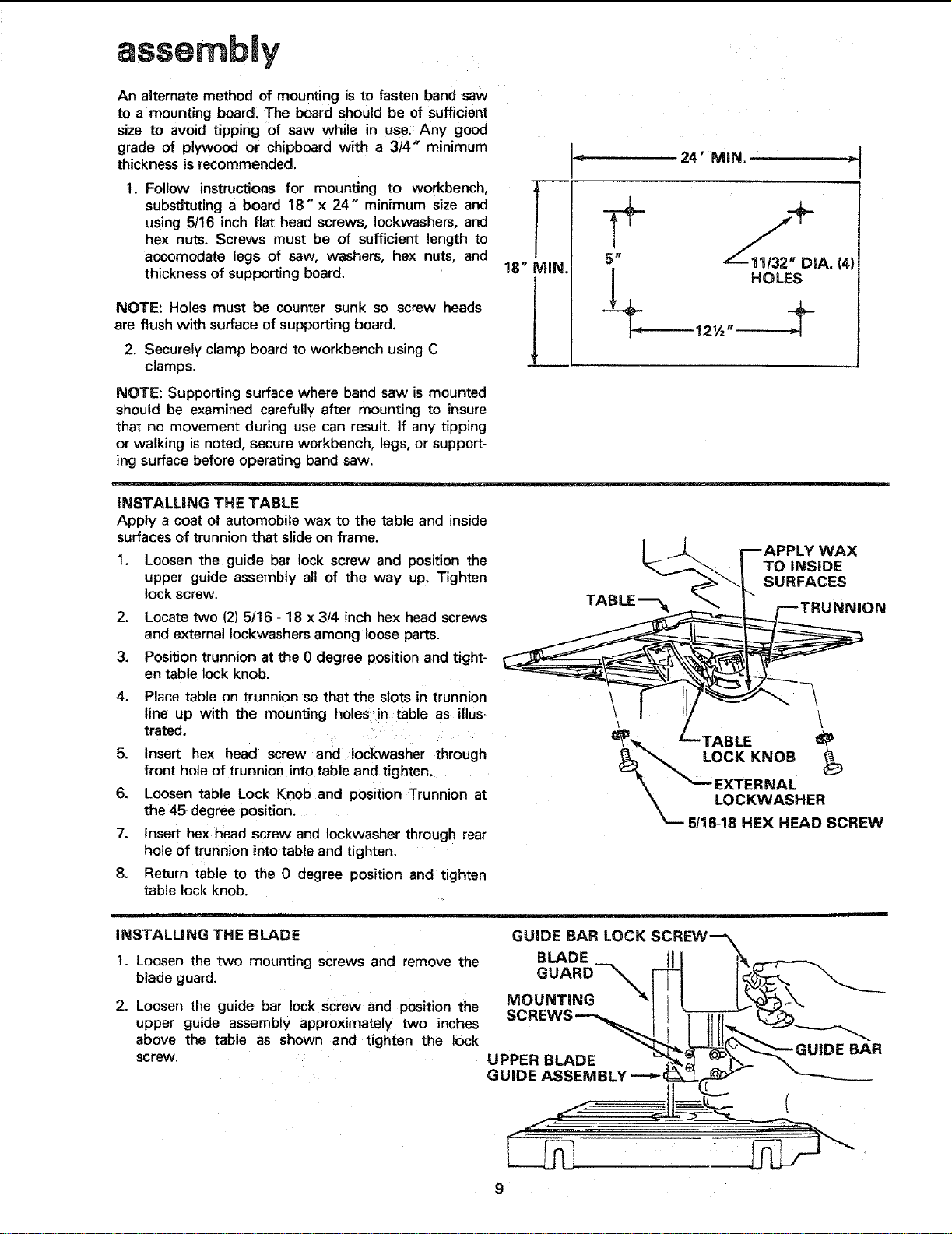
iNSTALLiNG THE TABLE
Apply a coat of automobile wax to the table and inside
surfaces of trunnion that slide on frame.
1. Loosen the guide bar lock screw and position the
upper guide assembly all of the way up. Tighten
lock screw.
2. Locate two (2) 5/16 - 18 x 3!4 inch hex head screws
and external Iockwashers among loose parts.
3. Position trunnion at the 0 degree position and tight-
en table lock knob.
4. Place table on trunnion so that the slots in trunnion
line up with the mounting holes in table as illus-
trated.
5. Insert hex head screw and Iockwasher through
front hole of trunnion into table and tigntan.
6. Loosen table Lock Knob and position Trunnion at
the 45 degree position.
7. Insert hex head screw and Iockwasher through rear
hole of trunnion into table and tighten.
8. Return table to the 0 degree position and tighten
table lock knob.
__.. mAPPLY WAX
TO iNSiDE
SURFACES
TABLE'--'_ _._TRUNN,ON
--TABLE _P
LOCK KNOB _
EXTERNAL
,,,o °?2Wx"S"22
iNSTALLING THE BLADE
1. Loosen the two mounting screws and remove the
blade guard.
2. Loosen the guide bar lock screw and position the
upper guide assembly approximately two inches
above the table as shown and tighten the lock
screw.
Loading ...
Loading ...
Loading ...