Loading ...
Loading ...
Loading ...
assembmy
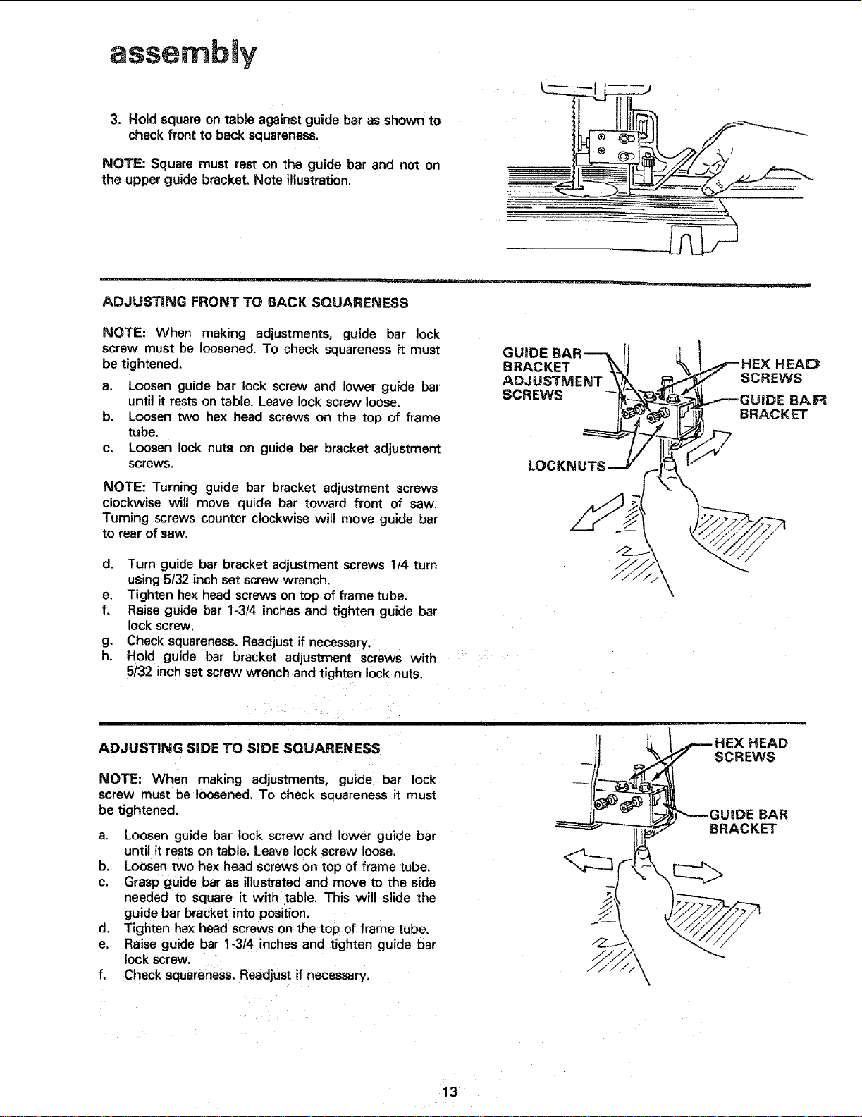
3. Hold squareon table againstguide bar as shown to
checkfront to back squareness.
NOTE: Square must rest on the guide bar and not on
the upper guide bracket. Note illustration.
ADJUSTING FRONT TO BACK SQUARENESS
NOTE: When making adjustments, guide bar lock
screw must be loosened. To check squareness it must
be tightened.
a. Loosen guide bar lock screw and lower guide bar
until it restson table. Leave lock screw loose.
b. Loosen two hex head screws on the top of frame
tube.
c. Loosen lock nuts on guide bar bracket adjustment
screws.
NOTE: Turning guide bar bracket adjustment screws
clockwise will move quide bar toward front of saw.
Turning screws counter clockwise will move guide bar
to rear of saw.
d. Turn guide bar bracket adjustment screws !/4 turn
using 5/32 inch set screw wrench.
e. Tighten hex head screws on top of frame tube,
f. Raise guide bar 1-314 inches and tighten guide bar
lock screw.
g, Check squareness. Readjust if necessary.
h. Hold guide bar bracket adjustment screws with
5/32 inch set screw wrench and tighten lock nuts.
GUIDE
BRACKET
ADJUST_
SCREWS
LOC_
HEAD
SCREWS
DE BAR
BRACKET
ADJUSTING SiDE TO SIDE SQUARENESS
NOTE: When making adjustments, guide bar lock
screw must be loosened. To check squareness it must
be tightened.
a. Loosen guide bar lock screw and lower guide bar
until it restson table. Leave lockscrew loose.
b. Loosentwo hex head screws on top of frame tube.
c. Grasp guide bar as illustratedand move m the side
needed to square it with table. This will slide the
guide bar bracket intoposition.
d. Tighten hexhead screwson the top of frame tube.
e, Raise guide bar 1-3/4 inches and tighten guide bar
lock screw.
f. Check squareness,Readjustif necessary.
m
HEAD
SCREWS
IIIDEBAR
BRACKET
!3
Loading ...
Loading ...
Loading ...