Loading ...
Loading ...
Loading ...
motor specifications and electrical
requirements
This power toot is equipped with a 3-conductor cord
and grounding type plug which has a grounding prong,
approved by Underwriters' Laboratories and the Cana-
dian Standards Association. The ground conductor has
a green jacket and is attached to the tool housing at
one end and to the ground prong in the attachment
plug at the other end.
This plug requires a mating 3-conductor grounded type
outlet as shown.
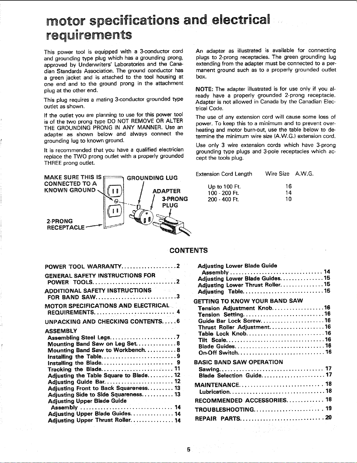
ff the outlet you are planning to use for this power tool
is of the two prong type DO NOT REMOVE OR ALTER
THE GROUNDING PRONG IN ANY MANNER. Use an
adapter as shown below and always connect the
grounding lug to known ground.
It is recommended that you have a qualified electrician
replace the TWO prong outlet with a properly grounded
THREE prong outlet.
An adapter as illustrated is available for connecting
plugs to 2-prong receptacles. The green grounding tug
extending from the adapter must be connected to a per-
manent ground such as to a properly grounded outlet
box.
NOTE: The adapter illustrated is for use only if you al-
ready have a properly grounded 2-prong receptacle.
Adapter is not allowed in Canada by the Canadian Elec-
trical Code.
The use of any extension cord will cause some loss of
power. To keep this to a minimum and to prevent over-
heating and motor burn-out, use the table below to de-
termine the minimum wire size (A.W.G.) extension cord.
Use only 3 wire extension cords which have 3-prong
grounding type plugs and 3-pole receptacles which ac-
cept the tools plug.
MAKE SURE THIS IS -_ GROUNDING LUG
CONNECTED TO A .@ 1 /
KNOWN GROUND \ ADAPTER
I / 3PRONG
RECEPTACLE /
Extension Cord Length
Wire Size A.W.G.
Up to 100 Ft. 16
100 - 200 Ft. 14
200 - 400 Ft. 10
CONTENTS
POWER TOOL WARRANTY ...................2
GENERAL SAFETY INSTRUCTIONS FOR
POWER TOOLS .............................2
ADDITIONAL SAFETY iNSTRUCTIONS
FOR BAND SAW ............................ 3
MOTOR SPECIFICATIONS AND ELECTRICAL
REQU IREMENTS ............................ 4
UNPACKING AND CHECKING CONTENTS ..... 6
ASSEMBLY
Assembling Steel Legs ....................... 7
Mounting Band Saw on Leg Set .............. 8
Mounting Band Saw to Workbench ........... 8
Installing the Table .......................... 9
Installing the Blade ......................... 9
Tracking the Blade ......................... 11
Adjusting the Table Square to Blade ......... 12
Adjusting Guide Bar ........................ !2
Adjusting Front to Back Squareness ......... 13
Adjusting Side to Side Squareness ........... 13
Adjusting Upper Blade Guide
Assembly ................................ 14
Adjusting Upper Blade Guides ............... 14
Adjusting Upper Thrust Roller ............... 14
Adjusting Lower Blade Guide
Assembly ................................ 14
Adjusting Lower Blade Guides ............... 15
Adjusting Lower Thrust Roller ............... 15
Adjusting Table ............................ 15
GETTING TO KNOW YOUR BAND SAW
Tension Adjustment Knob .................. 16
Tension Setting ............................ 16
Guide Bar Lock Screw ...................... 16
Thrust Roller Adjustment ................... 16
Table Lock Knob ........................... 16
Tilt Scale .................................. 16
Blade Guides ............................... 16
On-Off Switch .............................. 16
BASIC BAND SAW OPERATION
Sawing .................................... 17
Blade Selection Guide ...................... 17
MAINTENANCE ............................. 18
Lubrication ................................. 18
RECOMMENDED ACCESSORIES ............. 18
TROUBLESHOOTING ........................ 19
REPAIR PARTS ............................. 20
Loading ...
Loading ...
Loading ...