Loading ...
Loading ...
Loading ...
8
ON-OFF SWITCH
\
1
DN ADJUSTMENT KNOB---_
COVER RETAINING
CLiP (5 USEDJ
3
GUIDE BAR
LOCK SCREW
2
TENSION SETTING
(BNSIDE)
BLADE
GUIDES
\
4
UPPER THRUST
ROLLER ADJUSTMENT
GUARD
7
BLADE
GUmDES
8
TILT
SCALE
4
LOWER THRUST
ROLLER ADJUSTMENT
|
5
TABLE LOCK KNOB
FRONT BACK
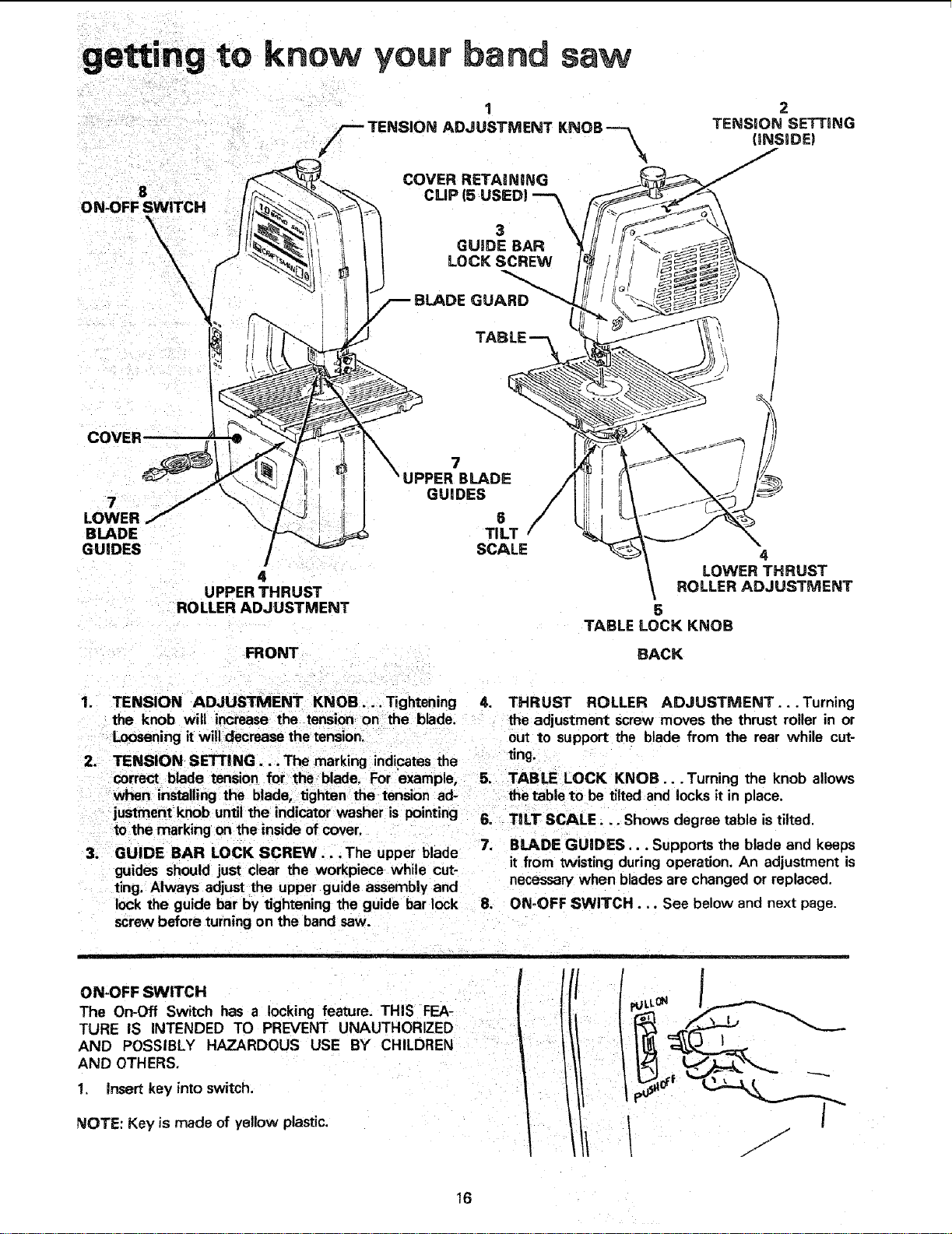
1. TENSION ADJUSTMENT KNOB .... Tightening 4. THRUST ROLLER ADJUSTMENT...Turning
the knob will increase the tension on the blade, the adjustment screw moves the thrust roller in or
Loosening it willdecrease the tension, out to support the blade from the rear while cut-
2. TENSION SETTING... The marking indicates the ring.
correct blade tension for the blade. For example, 5. TABLE LOCK KNOB... Turning the knob allows
when installing the blade, tighten the tension ad- the table to be tilted and locks it in place.
justment knob until the indicator washer is pointing 6. TILT SCALE... Shows degree table is tilted.
to the marking on the inside of cover.
3. GUIDE BAR LOCK SCREW...The upper blade 7. BLADE GUIDES... Supports the blade and keeps
guides should just clear the workpiece while cut- it from twisting during operation. An adjustment is
ting. Always adjust the upper guide assembly and necessary when blades are changed or replaced.
lock the guide bar by tightening the guide bar lock 8. ON-OFF SWITCH... See below and next page.
screw before turning on the band saw.
ON-OFF SWITCH
The On-Off Switch has a locking feature. THIS FEA-
TURE IS INTENDED TO PREVENT UNAUTHORIZED
AND POSSIBLY HAZARDOUS USE BY CHILDREN
AND OTHERS.
1. Insert key into switch.
NOTE: Key is made of yellow plastic,
I r//
pULLON /
/ ./
16
Loading ...
Loading ...
Loading ...