Loading ...
Loading ...
Loading ...
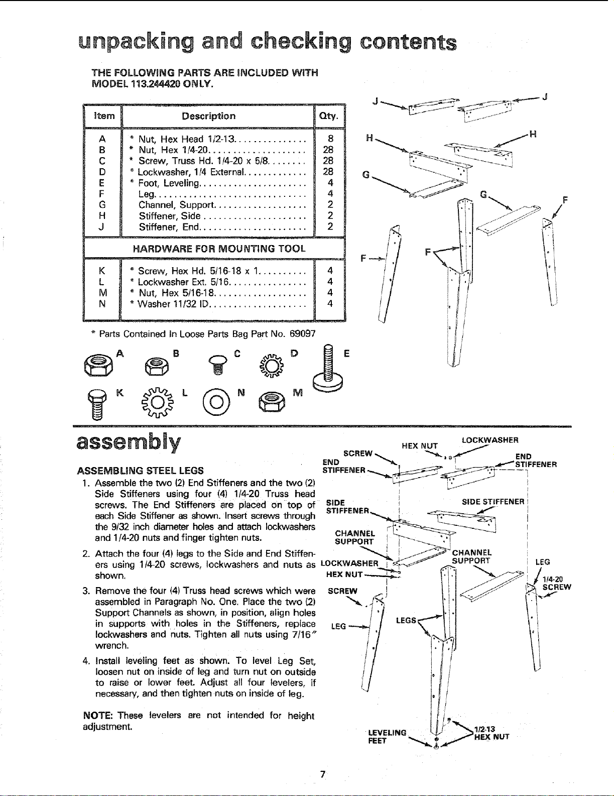
THE FOLLOWING PARTS ARE iNCLUDED WITH
MODEL 113.244420 ONLY.
_tem
A
B
C
D
E
F
G
H
J
Description
€$
QW.
Nut, Hex Head 112-t3 ............... 8
Nut, Hex 1/4-20 .................... 28
Screw, Truss Hd. 1/4-20 x 518........ 28
Lockwasher, 1/4 External ............. 28
Fore, Levering ...................... 4
Leg............................... 4
Channel, Support ................... 2
Stiffener, Side ..................... 2
Stiffener, End ...................... 2
K
L
M
N
HARDWARE FOR MOUNTING TOOL
Screw, Hex Hd. 5/16-18 x 1.......... 4
* Lockwasher Ext. 5/16 ................ 4
Nut, Hex 5/16-18 ................... 4
Washer 11/32 ID.................... 4
J _ _ _._---- J
F
/
Parts Contained in Loose Parts Beg Part No. 69097
assembly .EX.OT
LOCKWASHER
SCREW%= _. _l END
ASSEMELi NG STEEL LEGS .......... "--.,.,__ ______...... _j -----
1. Assemble the two (2) End Stiffeners and the two (2) _ ___J
Side Stiffeners using four (4) 1t4-20 Truss head t
screws. The End Stiffeners are placed on top of SiDE _ SIDE STIFFENER!
each Side Stiffener as shown. Insert screws through STIFFENER_ _,__
the 9/32 inch diameter holes and attach Iockwashers CHA"NEL r'___'_-_._
and 114-20nuts and finger tighten nuts. SUPPOR:r" ', _"-'_---_ _
2. Attach the four (4) legs to the Side and End Stiffen- _[ i _/_CHANNEL
ers using 1t4-20 screws, Iockwashers and nuts as LOCKWASHER __'_-_ SUPPORT LEG
shown. HEX NUT_
l
3. Remove the four (4) Truss head screws which were SCREW ! SCREW
assembled in Paragraph No. One. Place the two (2) _,. !._..; "_
Support Channels as shown, in position, align holes "/ LEGS_
in supports with holes in the Stiffeners, replace LEG
Iockwashers and nuts. Tighten all nuts using 7/16"
/
wrench. !
4. Install teveling feet as shown. To level Leg Set,
loosen nut on inside of leg and turn nut on outside /
to raise or lower feet. Adjust all four levelers, if
necessary, and then tighten nuts on inside of leg.
NOTE: These levelers are not intended for height
adjustment.
7
Loading ...
Loading ...
Loading ...