Loading ...
Loading ...
Loading ...
8 31-5000572 Rev. 1
ENGLISH
Overview of Unit
NOTES:
• The total indoor unit capacity should be less than or equal to the total outdoor unit capacity if all the outdoor units operate at the
same time in one system. Overloading operations may occur in bad operating condition or some special conditions. The total indoor
units capacity should be no more than 130% of the outdoor unit capacity.
• The total indoor units capacity should be less than the total outdoor unit capacity if the system operates in high heat load or very cold
areas. (ambient temperature below 14° F (10°C).
• To choose wire combinations and switch disconnections, refer to the unit specification guide.
Combinations and Options
1. Before installation, check if the model, power supply, pipe, wires, and parts purchased are correct.
2. Check to see if the indoor and outdoor units are properly matched according to the following table.
Outdoor Indoor
Combined
capacity range
Model(T)
Cooling Norminal
Capacity
kBtu/h
Combination Type
Maximum Number
of Connected Indoor
Units
Total indoor
capacity
kBtu/h
6 72 single 15 36~94
50%~130%
8 96 single 18 48~125
10 120 single 21 60~156
12 144 single 24 72~187
14 168 combination(6+8) 33 84~218
16 192 combination(8+8) 36 96~250
18 216 combination(10+8) 39 108~281
20 240 combination(10+10) 42 120~312
22 264 combination(10+12) 51 132~343
24 288 combination(12+12) 54 144~374
26 312 combination(8+8+10) 57 156~405
28 336 combination(10+10+8) 60 168~437
30 360 combination(10+10+10) 63 180~468
32 384 combination(12+10+10) 64 192~499
34 408 combination(12+12+10) 64 204~530
36 432 combination(12+12+12) 64 216~562
NOTES:
• The total indoor unit capacity should be less than or equal to the total outdoor unit capacity if all indoor units are operating at the
same time. The allowable ratio is 50 to 130%. Please consult the manufacturer if your needs exceed this limitation.
• The total indoor unit capacity should be less than the total outdoor capacity if system operating conditions are below 23°F or above 105°F.
• All electrical conductors should be sized according to the load they will carry.
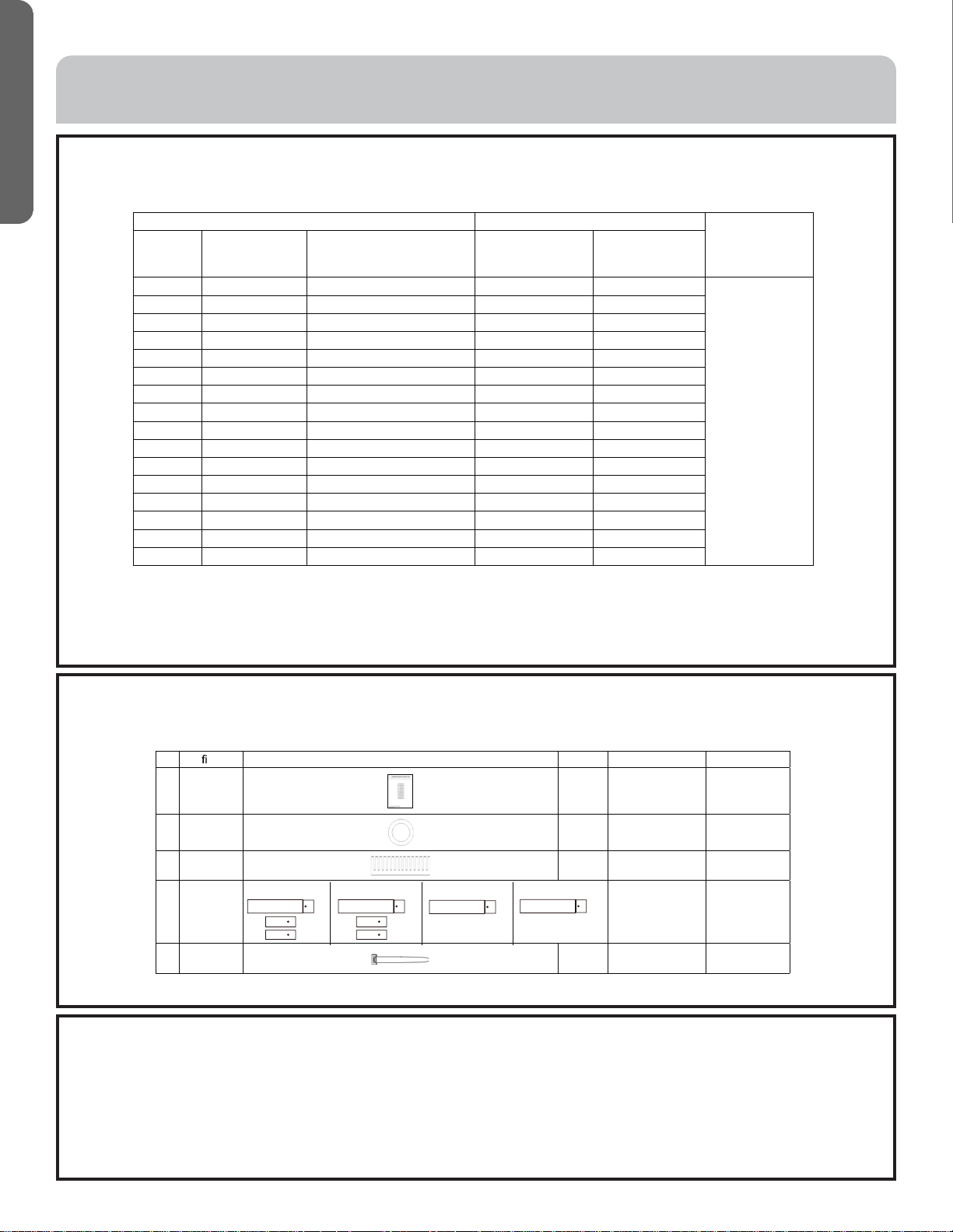
Accessories
Do not discard any of the accessories until installation is complete. Materials provided are needed for installation work.
Please check to make sure the accessory bag is complete.
No. De nition Graphic Quantity Remarks Place position
1
Installation
instruction
1 Accesory bag
2
Rubber
plug
1
Signal line
protection
Accesory bag
3 Sheath
1
Power line
protection
Accesory bag
4
Reducing
pipe
Reducing pipe Accesory bag
5 Zip ties
4
Gas liquid pipe
insulation binding
Accesory bag
(072)
1
1
1
(096)
1
1
1
(120)
1
(144)
1
INSTALLATION INSTRUCTIONS
Loading ...
Loading ...
Loading ...