Loading ...
Loading ...
Loading ...
31-5000572 Rev. 1 21
ENGLISH
INSTALLATION INSTRUCTIONS
Pipe Installation
Important
• Do not allow pipe to come in contact with equipment.
Vibration will cause leaks and noise.
• Close valves fully when brazing. Before burning the
sealing tube off, remove valve cap and confirm the
valve is closed completely, then remove charge cap and
connect charge pipe to pressure gauge by using hose to
confirm there is no residual refrigerant pressure.
• Protect service and access valves with a wet cloth while
brazing.
• Seal ends of piping prior to brazing to protect from
moisture and debris.
• Use a tubing bender to make changes in direction. Try to
maintain a radius at least 4 times the diamter of the tubing.
• All flare joints must be made with flaring tools designed
for R410A refrigerant. All fittings must be tightened with
a torque wrench to specifications listed in this manual.
¬Ýëìöèôøìóðèñ÷øöèöÙßÎòìïóïèäöèëäñçïèäææòõçìñêïü
• Use a torque wrench with a back up wrench when
tightening flare nuts to their proper torque. Torque
specifications are listed in the table below.
A
Pipe Outer Diameter (in) A°-0.4
1/4 9.1
3/8 13.2
1/2 16.6
5/8 19.7
B
Pipe Outer
Diameter
(in)
When it is hard pipe
Special tool
for R140A
The former
tool
1/4
0-0.5
1.0-1.5
3/8
1/2
5/8
• The outdoor gas pipe and the refrigerant distributing
pipe should be brazed with hard solder.
• Always purge lines with dry nitrogen while brazing to
prevent oxidation. Copper Oxide will contaminate the
refrigeration system.
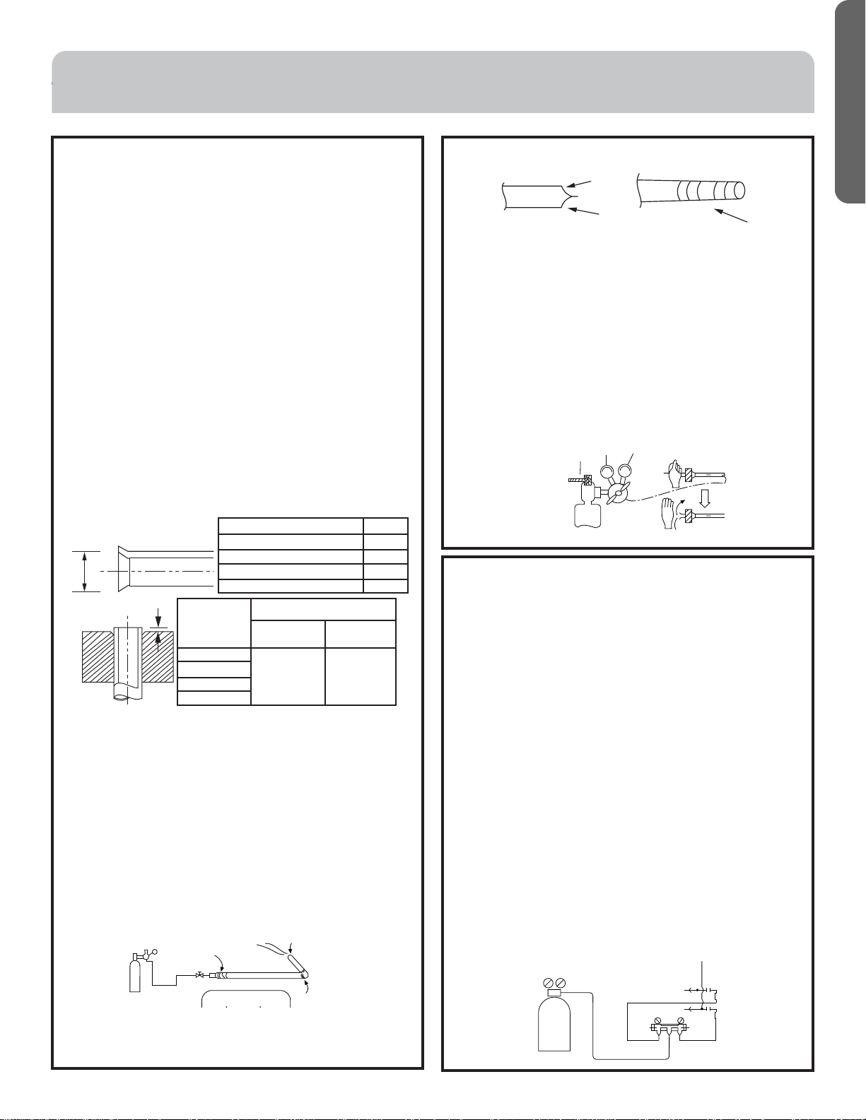
Operation Procedure
• Braze the pipe with nitrogen to prevent oxidation.
Copper oxide with form in the presence of oxygen and
contaminate the refrigeration system.
• Seal the pipe end with adhesive tape or a stopper to
increase the resistance, adjust nitrogen flow to about 2
to 3 IWC.
• Only nitrogen gas can be used.
Only nitrogen gas
bd
Brazing
<N2>
Taping
• Protect the pipe end against moisture and impurities
(welding after being flattened, or being sealed with
adhesive tape).
Pipe Installation (cont.)
• The refrigerant pipe should be clean. The nitrogen
should flow under the pressure of about 2 to 3 IWC and
when charging the nitrogen, restrict the flow at the open
end of the pipe. Turn off the valve at the opposite end to
force the nitrogen to flow in the correct direction.
• Close all valves fully when brazing all pipes. Before burning
the sealing tube off, remove valve cap and confirm the
valve is closed completely, then remove charge cap and
connect charge pipe to pressure gauge by using hose to
confirm there is no residual refrigerant pressure.
• Protect service and access valves with a wet cloth while
brazing.
1st side
Hand
2nd side
Source valve
29psi
Leakage Test
1. The outdoor unit has been leak tested at the factory.
Test field installed refrigerant lines and indoor units
separately from the sealed refrigeration system of the
outdoor unit. Do not connect refrigerant piping to stop
valves of outdoor unit when testing leakage.
2. Never use chlorine, oxygen, or flammable gasses when
testing for leaks. Apply nitrogen to both liquid and
vapor refrigerant lines while testing.
3. Apply the pressure incrementally to the target pressure.
a. Apply the pressure to 75 psi for more than 5 minutes,
æòñĨõðóõèööøõèõèðäìñöö÷äåïè
b. Apply the pressure to 220 psi for more than 5 minutes,
æòñĨõðóõèööøõèõèðäìñöö÷äåïè
c. Apply the pressure to the target pressure 500 psi,
record the temp. and the pressure.
d. Leave it at 500 psi for 24 hours to verify stable
pressure. Note that a temperature change of 1 degree
can cause a 1.45 psi change in pressure.
e. Use a trace amount of R410A refrigerant or soap
bubbles to confirm leaks if pressure test fails. Retest
after any repairs are made.
4. Evacuate the system after a successful pressure test.
Nitrogen
Hi handle
Gauge manifold
Hi
To indoor
Lo
Lo handle
Flat
Brazing Adhesive
Tape
Loading ...
Loading ...
Loading ...