Loading ...
Loading ...
Loading ...
Check SiUS121827E
232 Part 6 Service Diagnosis
8. Check
8.1 Thermistor Resistance Check
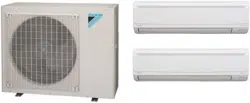
Check No.01 Measure the resistance of each thermistor using multimeter.
The resistance values are defined by below table.
If the measured resistance value does not match the listed value, the thermistor must be replaced.
Disconnect the connector of thermistor ASSY from the PCB to measure the resistance between
the pins using multimeter.
To check the thermistor soldered on a PCB, disconnect the PCB from other PCB/parts, and
measure the resistance between the both ends of soldered thermistor.
R6000517
Multimeter
Resistance range
Thermistor ASSY Soldered thermistor
Multimeter
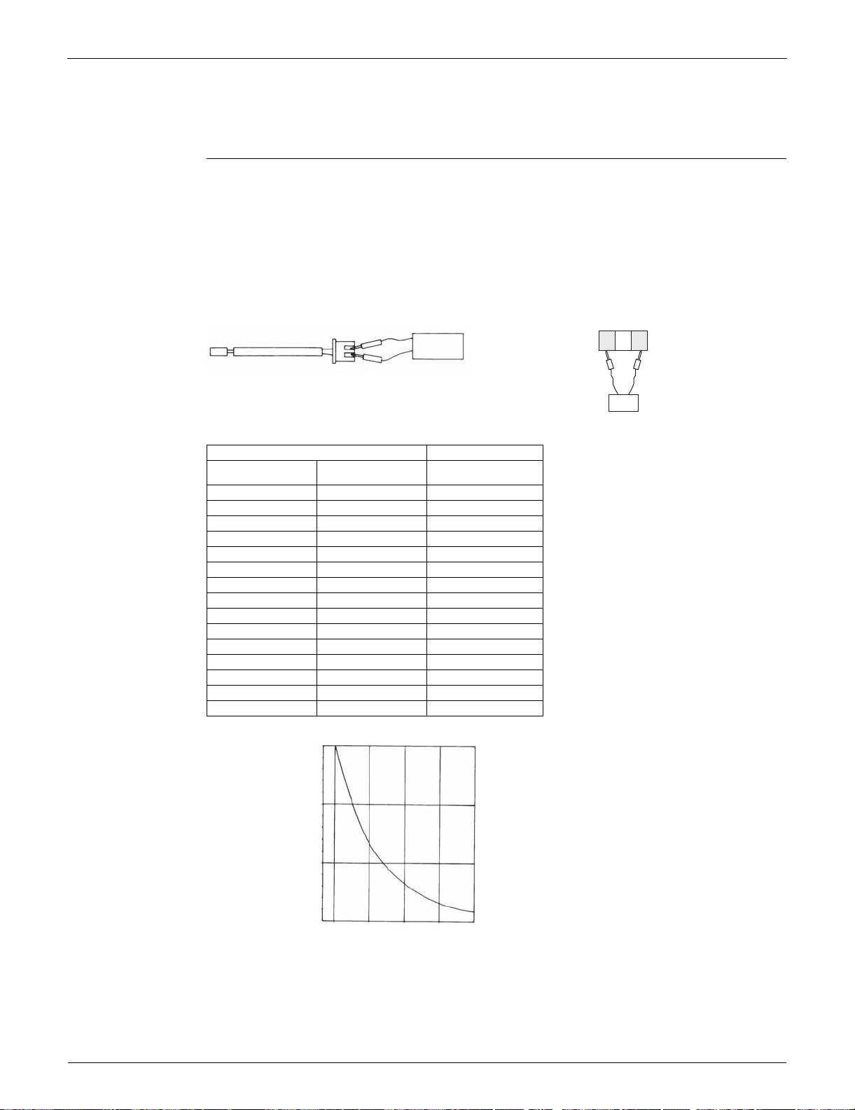
Thermistor temperature Type A
(°C) (°F)
R (25°C (77°F)) = 20 kΩ
B = 3950 K
–20 –4 197.8
–15 5 148.2
–10 14 112.1
–5 23 85.60
0 32 65.93
5 41 51.14
10 50 39.99
15 59 31.52
20 68 25.02
25 77 20.00
30 86 16.10
35 95 13.04
40 104 10.62
45 113 8.707
50 122 7.176
(kΩ)
150
100
50
–15 0 15 30 45
(R14467)
5 32 59 86 113
(°C)
(°F)
Loading ...
Loading ...
Loading ...