Loading ...
Loading ...
Loading ...
Namesof partsandcontrols
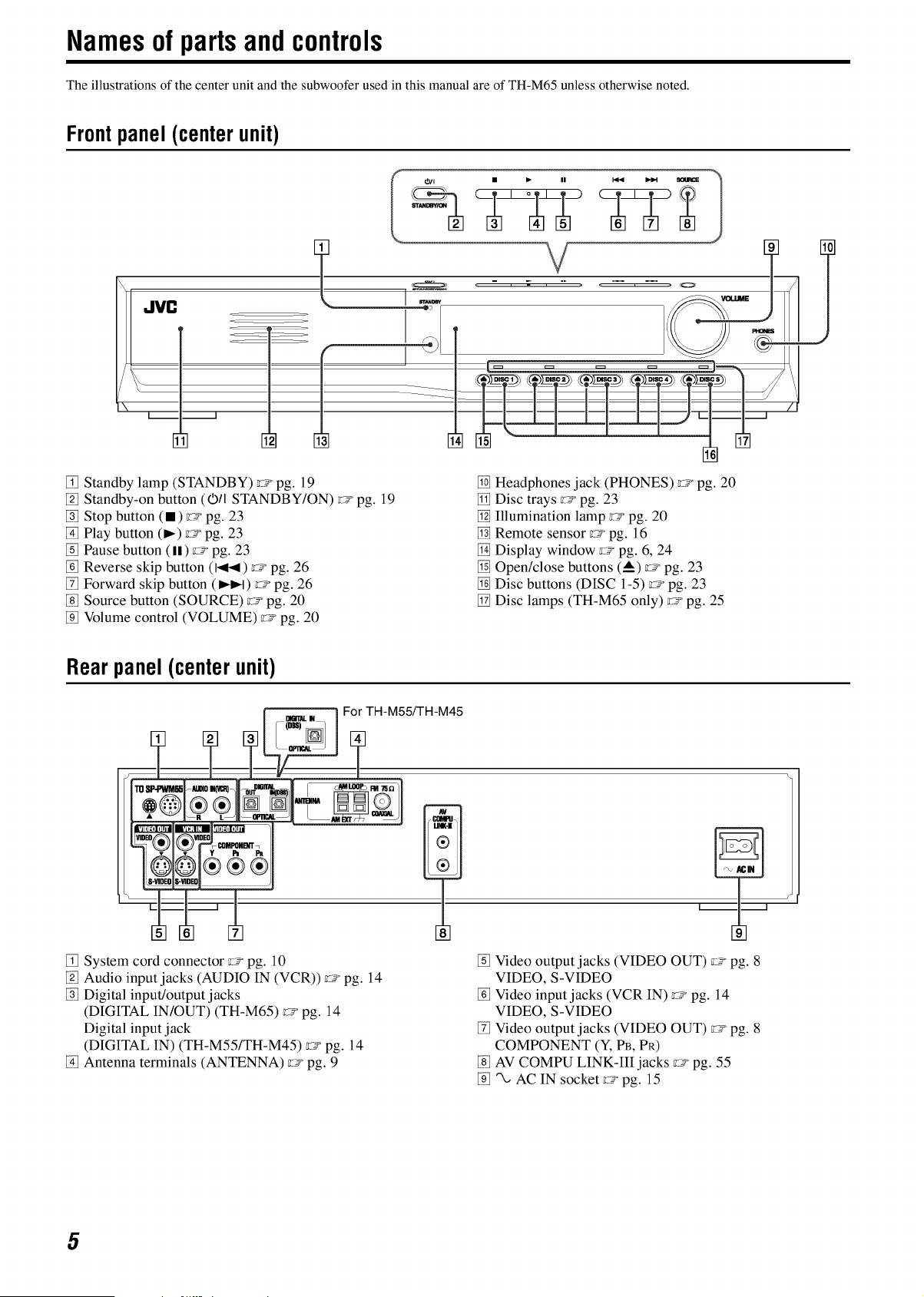
The illustrations of the center unit and the subwoofer used in this manual are of TH-M65 unless otherwise noted.
Frontpanel (centerunit)
l\ JVC
I
i
Standby lamp (STANDBY) _° pg. 19
[-4 Standby-on button (O/I STANDBY/ON) _° pg. 19
_] Stop button (•) _° pg. 23
_] Play button (_) _° pg. 23
Pause button (11) _° pg. 23
Reverse skip button (I.4-4) _° pg. 26
I-f7Forward skip button (_e,q) _° pg. 26
I-g]Source button (SOURCE) _° pg. 20
[-9_Volume control (VOLUME) _° pg. 20
N] Headphones jack (PHONES) _° pg. 20
N1 Disc trays _° pg. 23
_] Illumination lamp _° pg. 20
Remote sensor _° pg. 16
N] Display window _° pg. 6, 24
_] Open/close buttons (A) _o pg. 23
[] Disc buttons (DISC 1-5) _° pg. 23
[] Disc lamps (TH-M65 only) _° pg. 25
Rear panel(centerunit)
nOe,TAL_/ ] For TH-M55FFH-M45
System cord connector c_° pg. 10
[-4 Audio input jacks (AUDIO IN (VCR)) _° pg. 14
_] Digital input/output jacks
(DIGITAL IN/OUT) (TH-M65) _° pg. 14
Digital input jack
(DIGITAL IN) (TH-M55/TH-M45) _° pg. 14
_] Antenna terminals (ANTENNA) _° pg. 9
PU
Video output jacks (VIDEO OUT) _° pg. 8
VIDEO, S-VIDEO
Video input jacks (VCR IN) _° pg. 14
VIDEO, S-VIDEO
[-f_Video output jacks (VIDEO OUT) _° pg. 8
COMPONENT (Y, PB, PR)
I-g]AV COMPU LINK-Ill jacks _° pg. 55
[-9__ AC IN socket _° pg. 15
5
Loading ...
Loading ...
Loading ...