Loading ...
Loading ...
Loading ...
This quick reference guide explains steps to connect a TV and a DVD player to this unit and achieve the surround sound effects in a quick, easy manner.
This unit creates surround sound by reflecting proiected sound bealns off the wails of your listeniug room. Side view
The surround sound effects produced by this unit may not be sufficient when the unit is installed in the t_llowing locations.
Rooms with surfaces inadequate for reflecting sound beams 5 cm or more
Rooms with acoustically absorbent surfaces ............
Rootns with measurenlents outside the following range W (3 to 7 m) x H (2 to 3.5 m) x D (3 to 7 m)
Rooms with less than 2 m from the listening position to the speaker positions Front Rear
Rootns where objects such as flmliture are likely to obstruct the path of sound beams
Rooms where the listening position is close to the walls
Rootns where the listening position is not in front of this unit
Make sure you leave an adequate alnount of ventilatiou space so that heat can escape. Make at least 5 cm of space above or below this unit.
Install this unit where there are no obstacles such as flirniture obstructing the path of sound bealns. Otherwise, the desired surround sound effects lnay not be achieved.
You tnay install this unit in parallel with the wall or in the corner.
Parallel installation
Install this unit in the exact center of the wall when it
is lneasured froth the left and right corners.
Corner installation
Install this unit in tile corner at a 40 ° to 50 ° angle from
the adjacent walls.
40 ° to 50 °
I D
\
An object, such as furniture
An object, such as furniture
Installation example
Install this unit so that the sound beams
can be reflected off the walls.
Wrong Correct Correct
\
{ 1
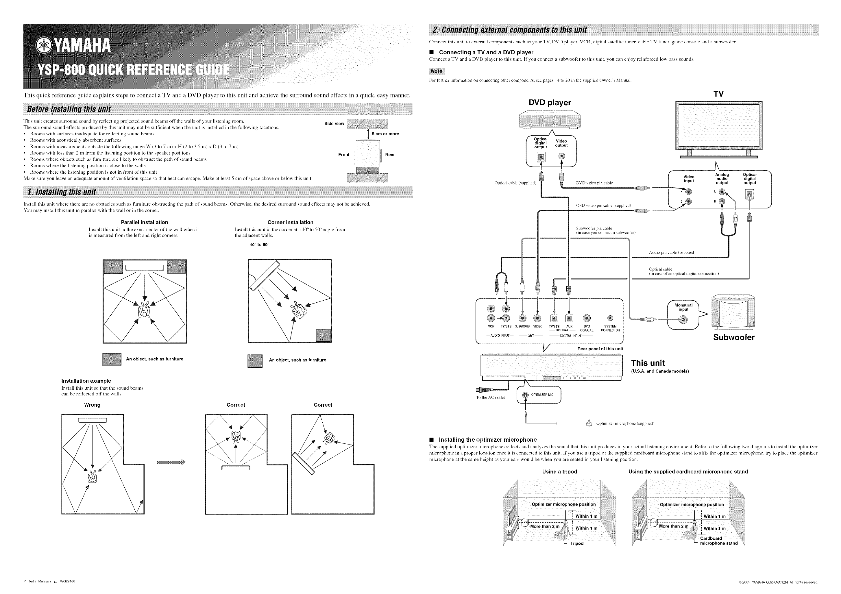
Connect this unit to external cotnponents such as your TV, DVD player, VCR, digital satellite tuner, cable TV tuner, game console and a subwoofer.
• Connecting a TV and a DVD player
Connect a TV and a DVD player to this unit. If you connect a subwoofer to this unit, you can enjoy reinforced low bass sounds.
For further information on connecting other con/lxments, see pages 14 to 20 in the supplied Owner's Manual.
DVD player
Oplical cable (supplied) DVD video pin cable
OSD video pin cable (supplied)
TV
i_ ii ii ii i i i
Subwoofer pin cable
®
VCR TV/STB SUBWOOFERVIDEO TV/STB AUX DVD SYSTEM
--OPTICAL-- COAXIAL CONNECTOR
-- AUDIO INPUT-- OUT DIGITAL INPUT'--
_/_ Rear panel of this unit
??i;;;;;;; ¸:%¸¸¸¸¸)i_;_)?i;;;;;;; ;;;; ;;;; ;;;;;;;; ;;;; ;;;;;;;;;;;; ;;;; ;;;; ;;;;;;;; ;7;i¸i:__;_?:; _;;;;
Analog Optical
Video audio digital
input output output
Oplical cable
!in case of an optical digital connection)
Subwoofer
I
To Ihe AC outlet
OPTIMIZER MIC 1
I II
This unit
(U.S.A. and Canada models)
I
Oplimizer microphone (supplied)
• Installing the optimizer microphone
The supplied optimizer microphone collects and analyzes the soui_M that this ui_lit produces ill your actual listeniug environtneut. Refer to the following two diagrams to install tile optimizer
microphone in a proper location once it is connected to this unit. If you use a tripod or the supplied cardboard microphone stand to affix the optimizer microphone, try to place the optimizer
microphone at the same height as your ears would be when you are seated in your listening position.
Using a tripod Using the supplied cardboard microphone stand
Printed in Malaysia (2 WG29100 @2005 YAMAHA CORPORATION All rights reserved.
Loading ...