OWNER'S MANUAL
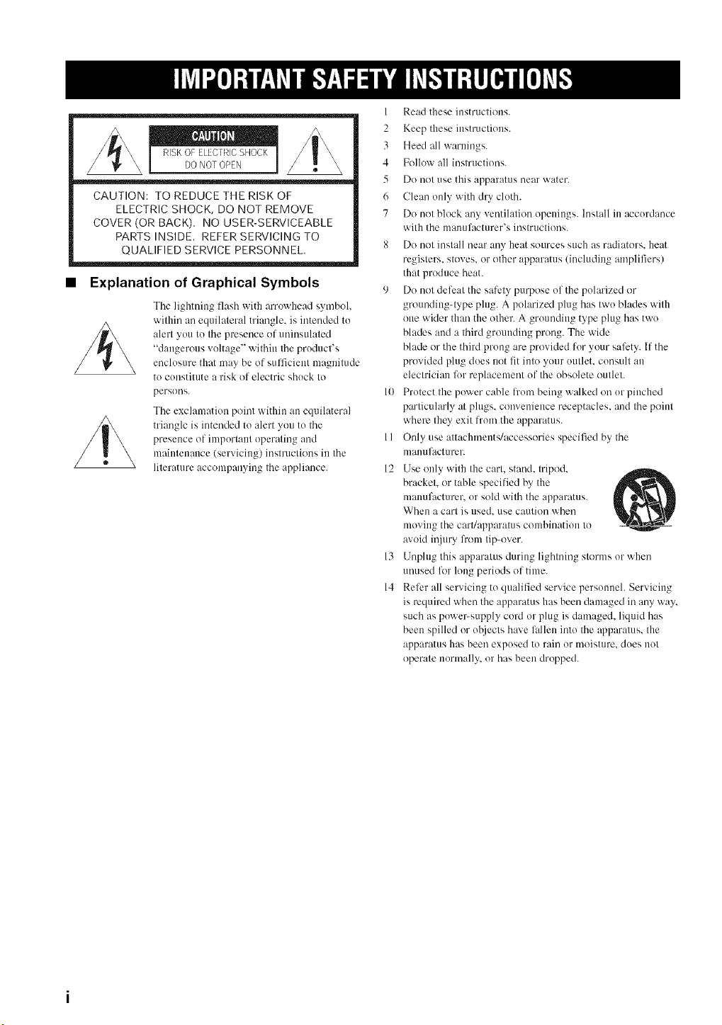
CAUTION: TO REDUCE THE RISK OF
ELECTRIC SHOCK, DO NOT REMOVE
COVER (OR BACK), NO USER-SERVICEABLE
PARTS INSIDE, REFER SERVICING TO
QUALIFIED SERVICE PERSONNEL,
• Explanation of Graphical Symbols
The lightning flash with arrowhead symbol,
within an equilaleral triangle, is intended tu
alerl you tu the presence of uninsulaled
"dangerous voltage" wilhin Ihe pruducl's
enclusm'e that may be uf sufficienl magnitude
to constitute a risk of electric shuck to
persuus.
The exclamation point within an equilateral
triangle is intended to alert you to the
presence of important operating and
maintenance (servicing) instructions in the
literature accompanying the appliance.
1
2
3
4
5
6
7
1o
11
12
13
14
Read these instructions.
Keep these instructions.
Heed all warnings.
Follow all instructions.
[)(/not use this apparatus near water.
Clean only with dry cloth.
[)(/not block any ventilation openings. Install in accordance
with the manuli_cturer's instructions.
Do not install near any heat sources such as radiators, heat
registers, stoves, or uther apparatus (including amplifiers)
that produce heat.
Do not defeat the safety purpose of the polarized or
groundiug4ype plug. A polarized plug has two blades with
one wider than the other. A grounding type plug has two
blades and a third grounding prong. The vdde
blade or the third prong are provided for your safety. If the
provided plug does not fit into your outlet, consult an
electrician for replacement of the obsolete outlet.
Protect the power cable h'um being walked on or pinched
particularly at plugs, convenience receptacles, and the point
where they exit from the apparatus.
Only use attachments/accessuries specified by the
nlanuli/cturer.
Use only with the cart, stand, tripod,
bracket, or table specified by the
manufacturer, or sold with the apparatus.
When a cart is used. use caution when
moving the cart/apparatus combination to
avoid ii!jury lhum tip-uver.
Unplug this apparatus during lightning stunns or when
unused for long periods of time.
Reli:r all servicing to qualified service personueh Servicing
is required when the apparatus has been damaged in any way,
such as puwe>supply cord or plug is damaged, liquid has
been spilled or uhjects have lidlen into the apparatus, the
apparatus has been exposed to rain or moisture, dues not
operate nonually, or has been dropped.
FCC INFORMATION (for US customers)
1. IMPORTANT NOTICE: DO NOT MODIFY THIS
UNIT!
This product, when installed as indicated in the instructions
contained in this manuah meets FCC requirements.
Modifications not expressly approved by YAMAHA may
void your authority, granted by the FCC. to use the product.
2. IMPORTANT:
When connecting this product to accessories and/or another
product use only high quality shielded cables. Cable/s
supplied with this product MUST be used. Follow all
installation instructions. Failure to lk)llow instructions could
void your FCC authorization to use this product in the USA.
3. NOTE:
This product has been tested and li)und to comply with the
requirements listed in FCC Regulations. Part 15 li)r Class
"B" digital devices. Compliance with these requirements
provides a reasonable level of assurance that your use of
this product in a residential environment will not result in
harmful interl'erence with other electronic devices.
This equipment generates/uses radio frequencies and. if not
installed and used according to the instructions l'ound in the
users manual, may cause interference harmfill to the
operation of other electronic devices.
Compliance with FCC regulations does not guarantee that
interference will not occur in all installations. If this product
is l'ound to be the source of interference, which can be
determined by turning the unit "OFF" and "ON", please try
to eliminate the problem by using one of the li)llowing
nleasuresl
Relocate either this product or the device that is being
affected by the interference.
Utilize power outlets that are on diflierent branch (circuit
breaker or fllse) circuits or install AC line filter/s.
In the case of radio or TV interference, relocate/reorient the
antenna. If the antenna lead-in is 300 ohm ribbon lead.
change the leadqn to coaxial type cable.
If these corrective measures do not produce satisfactory
results, please contact the local retailer authorized to
distribute this type of product. If you can not locate the
appropriate retailer, please contact YAMAHA Electronics
Corp.. U.S.A. 6660 Orangethorpe Ave. Buena Park. CA
90620.
The above statements apply ONLY to those products
distributed by YAMAHA Corporation of America or its
subsidiaries.
We Want You Listening For A Lifetime
YAMAHA and the Electronic Industries Association's Consumer Electronics Group want you to get the most out of
your equipment by' playing it at a safe leveh One that lets the sound come through loud and clear without annoying
N
blaring or distortion and. most importantly, withoul alfecting your sensitive hearing.
Since hearing damage from loud sounds is often undelectable until il is Ioo late. YAMAHA and the Electronic Industries _o
Association's Consumer Eleclronics Group recommend you to avoid prolonged exposure lrom excessive volume levels. LIS"TI_NING
To assure the finest perfi_rmance, please read this manual
1
carefully. Keep it in a sale place for future reference.
2 Install this sound system in a well ventilated, cool, dry, clean
place with at least 5 cm of space above (or below) this unit
away from direct sunlight, heat sources, vibration, dust, moisture,
and/or cold.
3 Locate tiffs unit away from other electrical appliances, motors, or
transl_rmers to avoid lmmming sounds.
4 Do not expose this unit to sudden temperature changes from cold
to hot, and do not locate tiffs unit in an environment with high
humidity (i.e. a room with a humidifier/ to prevent condensation
inside this unit, which may cause an electrical shock, fire,
damage to this unit, and/or personal injury.
5 Avoid installing this unit where fi_reign object may l.dl onto this
unit and/or this unit may be exposed to liquid dripping or
splashing. On the top of this unit, do not place:
Other components, as they may calse damage and/or
discoloration on the surlhce of this unit.
Burning objects (i.e. candles), as they may cause fire, damage
to this unit, and/or personal injury.
Containers will] liquid in them, as they may l.dl and liquid
may cause electrical shock to the user and/or damage to this
unit.
6 Do not cover this unit with a newspaper, tablecloth, curtain, etc.
in order not to obstruct heat radiation. If the temperature inside
this unit rises, it may cause fire, damage to this unit, and/or
personal injury.
7 Do not plug in Ibis unit to a wall outlet until all connections arc,
complete.
8 Do not operate this unit upside-down. It may overbear, possibly
causing damage.
9 Do not use force on switches, knobs and/or cords.
10 When disconnecting the power cable from the wall outlet, grasp
the plug; do not pull the cable.
1] Do not clean this unit with chemical solvents: this might damage
the finish. Use a clean, dry cloth.
12 Only voltage specified on lifts unit must be used. Using this unit
with a higher voltage than specified is dangerous and may cause
tim, damage to this unit, and/or personal injury. YAMAHA will
not be held responsible for any damage resulting from use of this
unit with a voltage other than specified.
13 Do not attempt to modify or fix this unit. Contact qualified
YAMAHA service personnel when any service is needed.
The cabinet should never be opened lk_rany reasons.
14 When not planning to use this unit for long periods of time (i.e.
vacation), disconnect the AC power plug from the wall outlet.
15 Be sure to read the "TROUBLESHOOTING" section on
common operating errors before conchlding that this unit is
fauhy.
16 Before moving this unit, press STANDBY/ON to set this unit in
standby mode, and disconnect the AC power plug from the wall
outlet.
17 Condensation will lkwmwhen the surrounding temperature
changes suddenly. Disconnect the power cable fi'om the outlet,
then leaxe the unit alone.
18 When using the unit l\)r a long time, the unit may become warm.
Turn the power off, then leme the unit alone for cooling.
19 Install this unit near the AC outlet and where the AC power plug
can be reached easily.
WARNING
TO REDUCE THE RISK OF FIRE OR ELECTRIC SHOCK,
DO NOT EXPOSE THIS UNIT TO RAIN OR MOISTURE.
This unit is not disconnected from the AC power source as
long as it is connected to the AC wall outlet, even if this unit
itself is turned oil This state is called the standby mode. In
this state, this unit is designed to consume a very small
quantity of power.
FOR CANADIAN CUSTOMERS
To prex ent electric shock, match wide bhlde of plug to wide
slot and fidly insert.
This Class B digital apparatus complies with Canadian ICES-
003.
IMPORTANT
Please record the serial number of this unit in the space helow.
MODEL:
Serial No.:
The serial number is located on the rear of the unit. Retain this
Owner's Manual in a sali: place for fimtre reli_rence.
FOR U.K. CUSTOMERS
If the socket outlets it] the home are not suitable for the plug
supplied with this appliance, it should be cut off and an
appropriate 3 pin plug fitted. For details, refer to the
instructions described below. Note that the plug severed from
the mains lead must be destroyed, as a plug with bared
flexible cord is hazardous if engaged in a live socket outlet.
IMPORTANT
THE WIRES IN MAINS LEAD ARE COLOURED IN
ACCORDANCE WITH THE FOLLOWING CODE:
Blue: NEUTRAL
Brown: LIVE
As the colours of the wires in the mains lead of this apparatus
may not correspond with the coloured markings identil_ing
the terminals in your plug, proceed as follows:
The wire which is coloured BLUE must be connected to the
terminal which is marked with the letter N or coloured
BLACK. The wire which is coloured BROWN must be
connected to the terminal which is marked with the letter L or
coloured RED. Make sure that neither core is comtected to the
earth terminal of the three pin plug.
CAUTION
Danger of explosion if battery is incorrectly replaced. Replace
only with the same or equivalent type.
CAUTION
Use ol controls or a_[justments or perform:race of procedures
other than those specified herein may result in hazardous radi-
ation exposure.
iii
r
OVERVIEW ........................................................... 2
FEATURES ............................................................. 3
[]SING THIS MANUAL ........................................ 4
SUPPLIED ACCESSORIES ................................. 5
CONTROLS AND FUNCTIONS ......................... 6
Front panel ................................................................. 6
Front panel display .................................................... 7
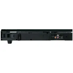
Rear panel .................................................................. 8
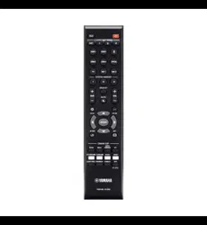
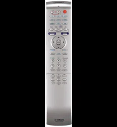
Remote control ........................................................... 9
INSTALLATION ................................................. 11
Belk_re installing this unit ......................................... 11
Installing this unit .................................................... 11
CONNECTIONS .................................................. 14
Connecting a TV ...................................................... 15
Connecting a DVD player/recorder ......................... 16
Connecting a VCR ................................................... 17
Connecting a digital satellite tuner
or a cable TV tuner .............................................. 18
Commcting other external components ................... 19
Commcting a subwooler .......................................... 20
Connecting the power supply cable ......................... 21
GETTING STARTED .......................................... 22
Installing batteries in the remote control ................. 22
Operation range of the remote control ..................... 22
1]sing the remote control ......................................... 23
Turning on the power ............................................... 23
[]SING SET MEN[] .............................................. 24
Displaying the OSD ................................................. 24
The flow chart of SET MENU ................................. 25
AUTO SETUP ....................................................... 26
The flow chart of AUTO SETUP ............................ 26
Installing the optimizer microphone ........................ 27
Using AUTO SETUP .............................................. 28
USING THE SYSTEM MEMORY .................... 34
Saving settings ......................................................... 34
Loading settings ....................................................... 35
PLAYBACK .......................................................... 37
Selecting the input source ........................................ 37
Playing back sources ............................................... 38
A@lsting the vohmm ............................................... 38
Muting the sound ..................................................... 39
BEAM MODE ....................................................... 4t)
5 beam mode ............................................................ 41
Stereo plus 3 beam mode ......................................... 41
3 beam mode ............................................................ 42
Stereo mode ............................................................. 42
Target mode ............................................................. 43
ENJOYING SURROUND SOUND ..................... 44
Ei!joying 2-chamml sources
in surround sound ................................................ 45
Ei]joyiog TV in surround sound .............................. 46
A@Bting surround mode parameters ...................... 47
[]SING SOUND FIELD PROGRAMS ................ 49
What is a sound field'? ............................................. 49
Turning on CINEMA DSP programs ...................... 50
Turning off CINEMA DSP programs ..................... 51
A_[justing CINEMA DSP levels .............................. 51
USING THE VOLUME MODE .......................... 52
[]SING TruBass ..................................................... 54
[]SING THE SLEEP TIMER .............................. 55
Setting the sleep timer ............................................. 55
Canceling the sleep timer ........................................ 56
BASIC SETUP ....................................................... 57
MANUAL SETUP ................................................. 63
Using MANUAL SETUP ........................................ 64
BEAM MENU ......................................................... 65
SOUND MENU ....................................................... 69
INPUT MENU ......................................................... 71
DISPLAY MENU .................................................... 73
ADJUSTING SYSTEM PARAMETERS ........... 75
Setting the maximum volume level ......................... 75
Protecting the current settings ................................. 76
Initializing the current settings ................................ 77
A@lsting the audio balance .................................... 78
SELECTING THE INPUT MODE ..................... 81
REMOTE CONTROL FEATURES ................... 82
Setting remote control codes ................................... 82
Controlling other components ................................. 83
Using the TV macro ................................................ 85
J
TROUBLESHOOTING ....................................... 87
GLOSSARY ........................................................... 9{}
Audio formats .......................................................... 90
Audio information ................................................... 90
INDEX .................................................................... 91
SPECIFICATIONS ............................................... 92
I
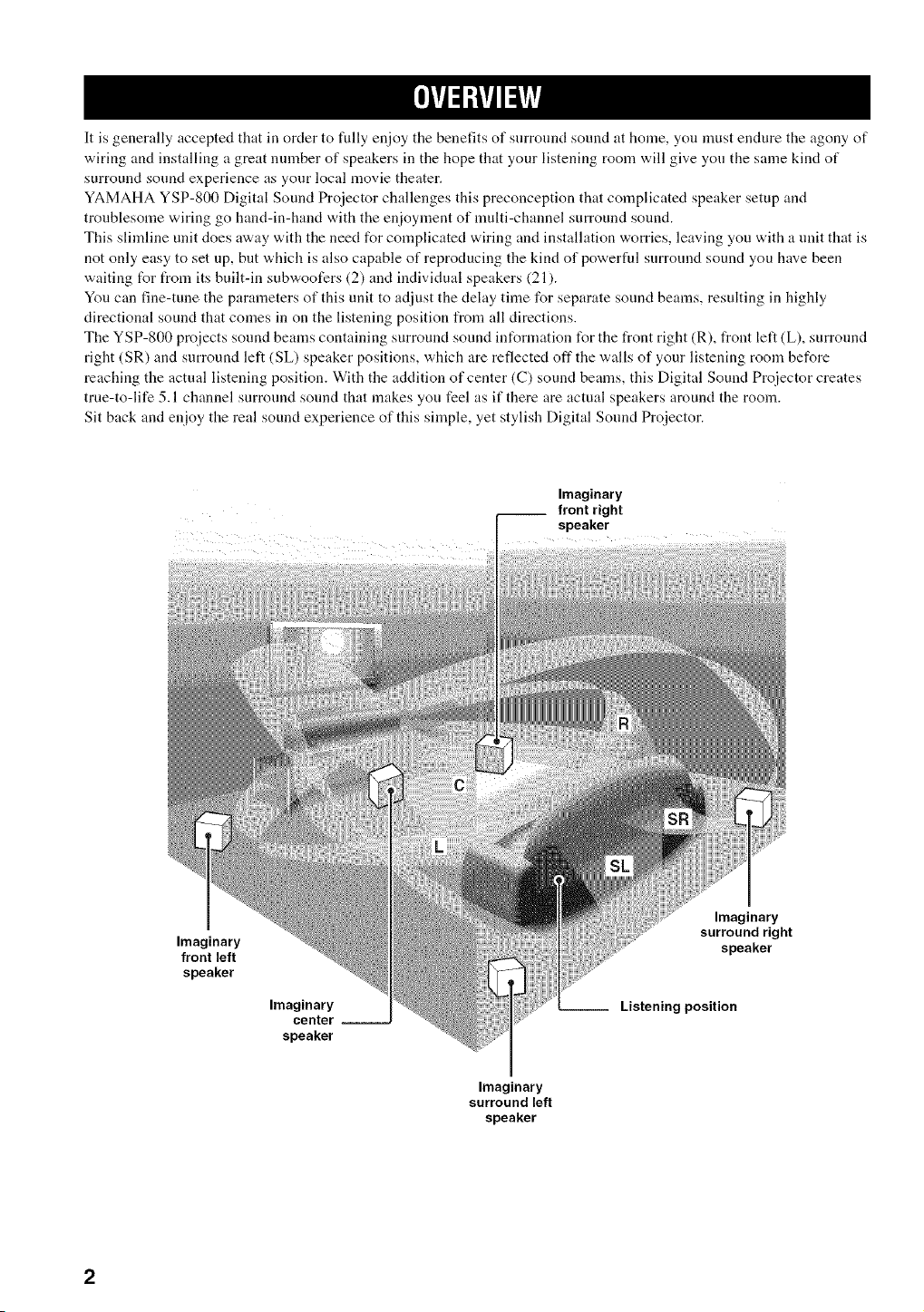
It is generally accepted that in order to fully enjoy the benefits of surronnd sound at home, you must endure the agony of
wiring and installing a great nmnber of speakers in the hope that your listening room will give you the same kind of
surround sound experience as your local movie theater.
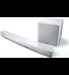
YAMAHA YSP-800 Digital Sound Proiector challenges this preconception that complicated speaker setup and
troublesonle wiring go hand-in-hand with the enioyment of nmlti-channel surround sound.
This slimline unit does away with the need for complicated wiring and installation worries, leaving you with a unit that is
not only easy to set up, but which is also capable of reproducing the kind of powerful snrronnd sound you have been
waiting tUr from its built-in subwoofers (2) and individual speakers (21).
You can fine-tune the parameters of this unit to adjust the delay time for separate sound beams, resulting in highly
directional sound that comes in on the listening position from all directions.
The YSP-800 projects sound beams containing surround sound int_rmation for the front right (R), front left (L), surround
right (SR) and surround left (SL) speaker positions, which are reflected oft"the walls of your listening room before
reaching the actual listening position. With the addition of center (C) sound beams, this Digital Sound Pro}ector creates
true-to-life 5.1 channel surround sonnd that makes yon feel as if there are actual speakers around the room.
Sit back and enioy the real sound experience of this simple, yet stylish Digital Sonnd Projector.
Imaginary
front right
speaker
....
Imaginary
front left
speaker
Imaginary
center --
speaker
Imaginary
surround right
speaker
Listening position
Imaginary
surround left
speaker
DigitalSoundProjector
This unit employs tlle digital sound projector technology
that allows one slim unit to control and steer nmltiple
channels of sound to generate full, physical 5.1 channel
surround sound, thus eliminating the need for satellite
loudspeakers and cabling normally associated with
conventional surround sound systems. This unit is also
equipped with the following 5 beam modes so that you can
choose the behavior of sound beams that best matches
your listening environment.
• 5 beam mode
• ST(STEREO)+3 beam mode
• 3 beam mode
• Stereo mode
• Target mode
Cinema DSP Digital
This unit employs the Cinema DSP Digital technology
developed by YAMAHA Electronics Corp. so that you can
experience movies at home with all the dramatic sound
impact that the director intended to convey.
OSD (on-screen display)
This unit employs the OSD which is basically a
superimposed screen image displayed on your video
monitor. The OSD is used to display the system
int_rmation or adjust settings for the system parameters.
Versatile Remote Control
The supplied remote control come "a.ith preset remote
control codes to be used to control the DVD player, VCR,
cable TV tuner and digital satellite tuner connected to this
unit. In addition, the remote control is equipped with the
macro capability so that you can pert_rm a series of
operations with the press of a single button.
I CINErV'i_
The "_" logo :rod "Cinmna DSP' are registered
tradmnarks of YAMAHA Corporation.
glrl
DIGITAL
Manufactured udder license l'roTn Dolb> Laboratories.
"Dolby', "Pro Logic", and the double-D symbol are trademarks
of Dolby Laboratories.
"DTS'. and "Neo:6" are trademarks of Digital Theater Systmns.
Inc.
AUTO SETUP
This unit employs the automatic sound beam optimization
using the YAMAHA Parametric Room Acoustic
Optimizer (YPAO) technology with the aid of the supplied
optimizer microphone so that you can avoid troublesome
listening-based speaker setup and achieve highly accurate
sound beana adjustments that best match your listening
environment.
Compatibility with the Newest Technologies
This unit employs decoders compatible with Dolby
Digital, DTS (Digital Theater Systems), Dolby Pro Logic,
Dolby Pro Logic I] and DTS Neo:6.
• Dolby Digital
This is the standard audio signal lbrmat used on DVDs and
other purely digital media. This surround technology deliver
high-quality digital audio lot up to 5.1 discrete channels to
produce a directional and more realistic effect.
• DTS (Digital Theater Systmns)
This is an audio signal format used on DVDs and other purely
digital media. This surround technology deliver high-quality
digital audio li)r up to 5.1 discrete channels to produce a
directional and more realistic efli:ct.
• Dolby Pro Logic
This sophisticated, matrix decoding technology up-converts
any 2 channel source audio to a 5.1 channel full baDdwklth
playback, resulting in a surround sound experience.
• Dolby Pro Logic 1I
This is lundameutally a redesigned version of Dolby Pro
Logic that mnploys 2 stereo surround chalmels, a subwooli_r
and a greatly enhanced steering logic. As a result, this
improved technology provides an exceptionally stable sound
fiekl that simulates 5.1 to a much greater degree than the
original Dolby Pro Logic. In addition. Dolby Pro Logic I1
leatures Movie. Music and (;ame modes specifically designed
lbr movies, music and games respectively.
• DTS Neo:6
This technology decodes the conventional 2 channel sources
lbr 6 chamml playback, enabling playback with the lhlbrange
channels with higher separation. Music mode and Cinema
mode are available to play back music and movie sources
respectively.
Manulqctured udder license from 1Ltd. Worhlwide patents
applied %r.
The' g;{'; ' logo add 'Digilal Sound Projector _" fire trademarks
of 1 Ltd.
SR$(@)
TruBass. SRS and the "(0) " syn9 _ol :ire registered trademarks
of SRS Labs. Inc. TruBass technology is incorporated udder
license l?om SRS Labs. Inc.
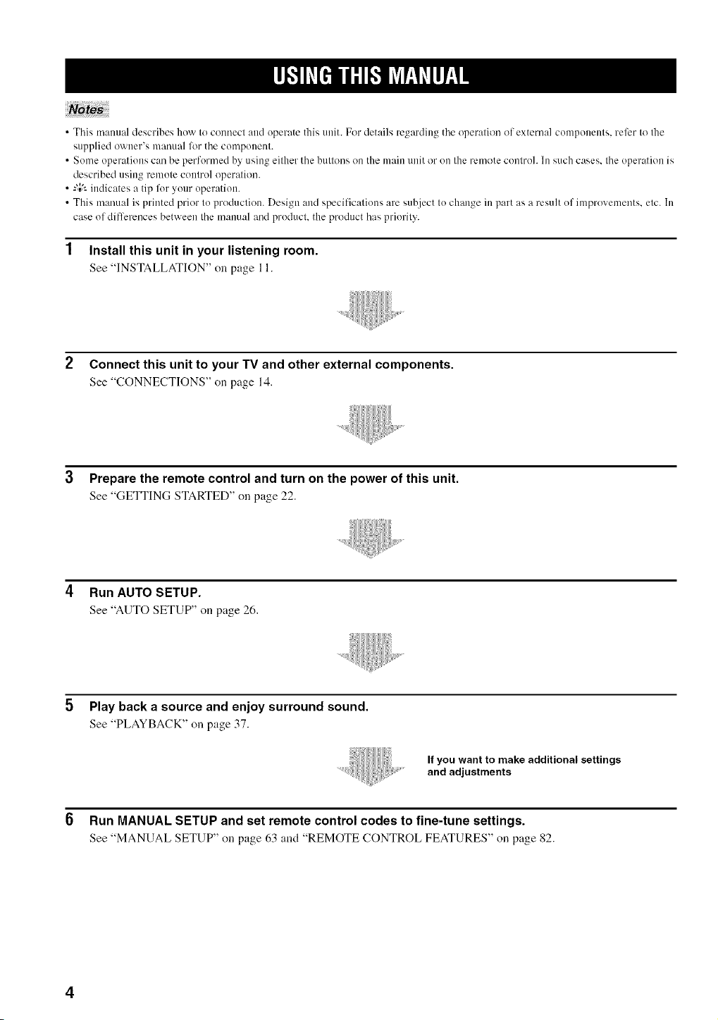
•Thismanualdescribeshowtoconnectandoperatethisunit.Fordetailsregardingtheoperationofexternalcomponents,rel_:rtothe
suppliedowner'smanuallZwthecomponent.
• SomeoperationscanbeperformedbyusingeitherthebuttonsonthemainunitorontheremotecoutrohInsuchcases,theoperationis
describedusingremotecontroloperation.
•-"4;'-indicatesatipforyouroperation.
•Thismanualisprintedpriortoproduction.Designandspecificationsaresubjecttochangeinpartasaresultofimprovements,etc.In
caseofdiflcreucesbetweenthemanualandproduchtheproducthaspriority.
1 Install this unit in your listening room.
See "INSTALLATION"on page 11.
2 Connect this unit to your TV and other external components.
See "CONNECTIONS" on page 14.
3 Prepare the remote control and turn on the power of this unit.
See "GETTING STARTED" on page 22.
4 Run AUTO SETUP.
See "AUTOSETUP" on page 26.
Play back a source and enjoy surround sound.
See "PLAYBACK" on page 37.
If you want to make additional settings
and adjustments
6 Run MANUAL SETUP and set remote control codes to fine-tune settings.
See "MANUAL SETUP" on page 63 and "REMOTE CONTROL FEATURES" on page 82.
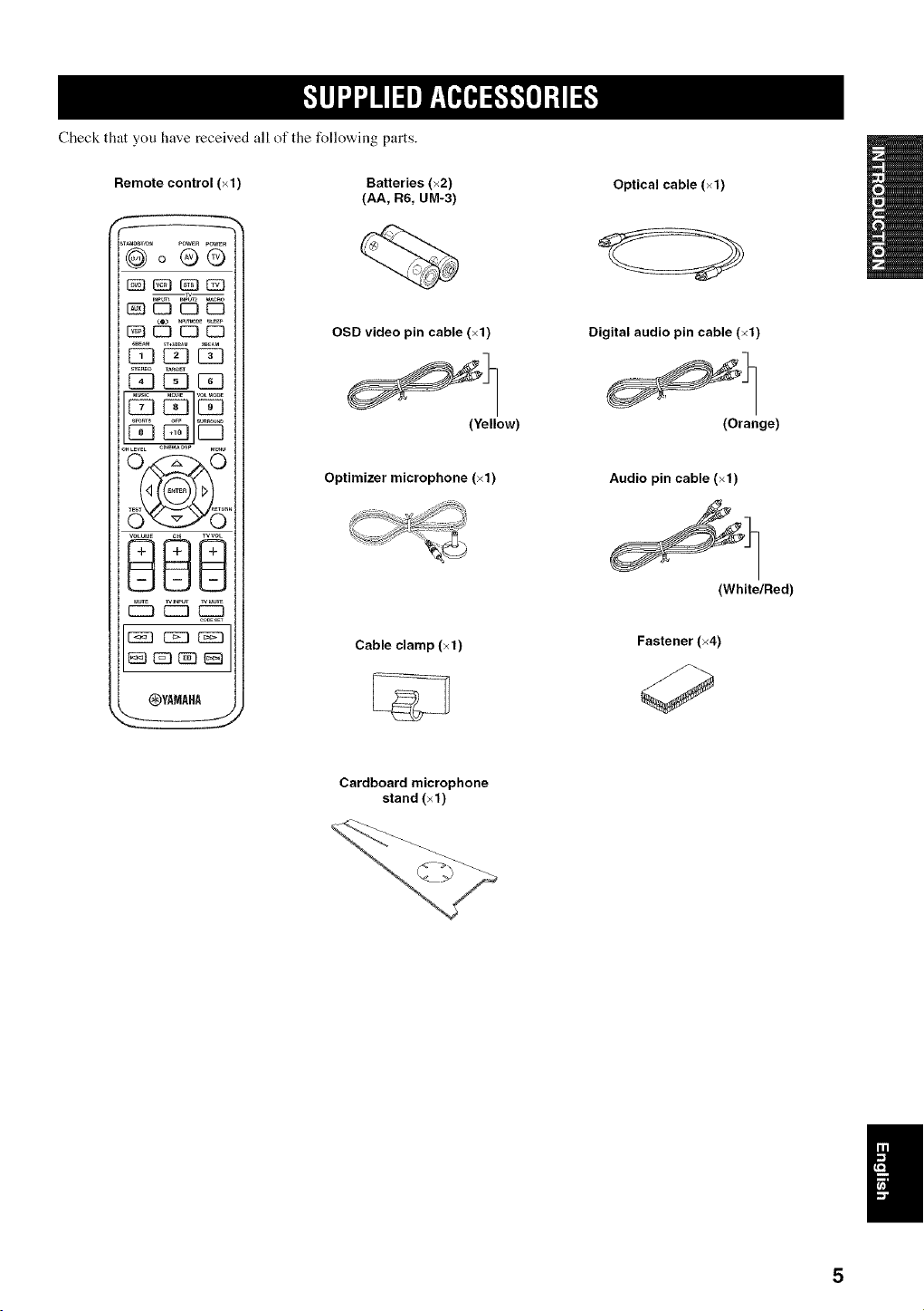
Checkthatyouhavereceivedallofthefollowingparts.
Remote control (×1)
POWERPOWER
@00o
_ EZ3EZI C3
SBE_ ,T*Se_M S_AM
C_LEVEL CI_E_ DSP M_,_
OYAMAHP_
Batteries (×2)
(AA, R6, UM-3)
OSD video pin cable (×1)
(Yellow)
Optimizer microphone (×1)
Cable clamp (×1)
Optical cable (×1)
Digital audio pin cable (×1)
(Orange)
Audio pin cable (×1)
(White/Red)
Fastener (×4)
Cardboard microphone
stand (×1)
I;3 [3 f "]
f
I (5
I
INPUT VOLUME
+ STANDBYION 1
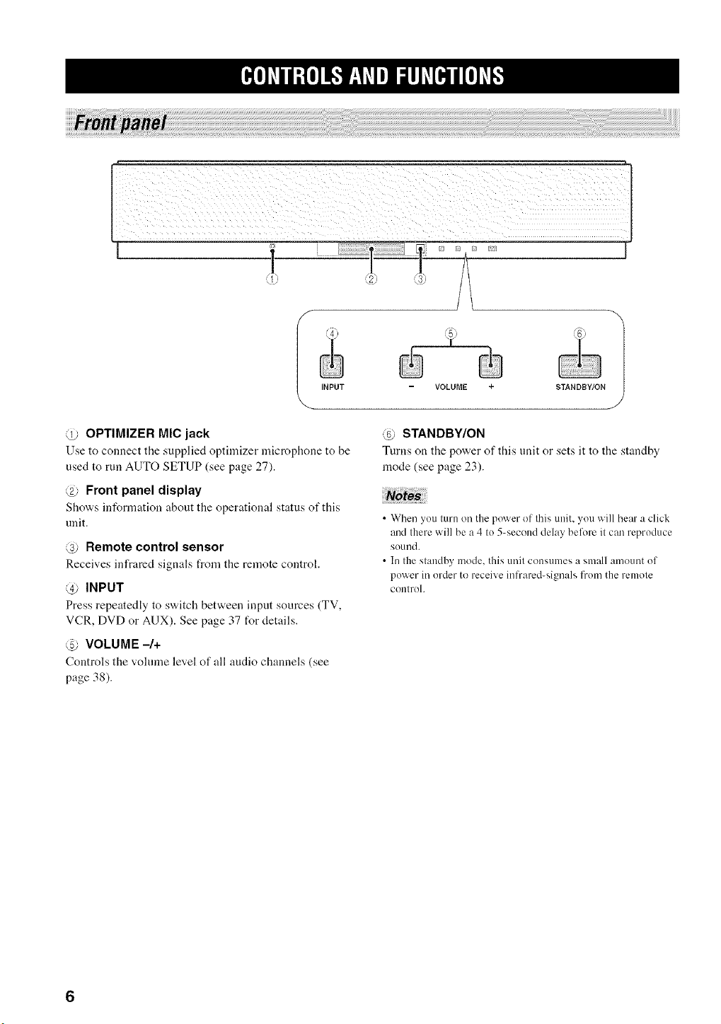
@ OPTIMIZER MIC jack
Use to connect tile supplied optimizer microphone to be
used to run AUTO SETUP (see page 27).
@ Front panel display
Sho'a,s inforn]ation about the operational status of this
unit.
@ Remote control sensor
Receives infrared signals from the remote control.
@ INPUT
Press repeatedly to s'a,itch between input sources (TV,
VCR, DVD or AUX). See page 37 for details.
@ VOLUME -/+
Controls the vohnne level of all audio channels (see
page 38).
@ STANDBY/ON
Turns on the power of this unit or sets it to the standby
mode (see page 23).
• When you turn on the power of this unit, you will hear a click
and there will be a 4 to 5-second delay before it can reproduce
sound.
• In the standby mode, this unit consumes a small amount of
power in order to receive infrared-signals fron/the remote
controh
_e]_Vll;£e]J_'JF_,T_Vel_lJ_V[e_Jl[e]_v[,
_? (i_' _i_
PCM DODJGJTALDOPL_
Hnl IIHm nHa lIHI gnil HIH aHH HUH mnH nSH _H_
r
[
_u
_u
_u
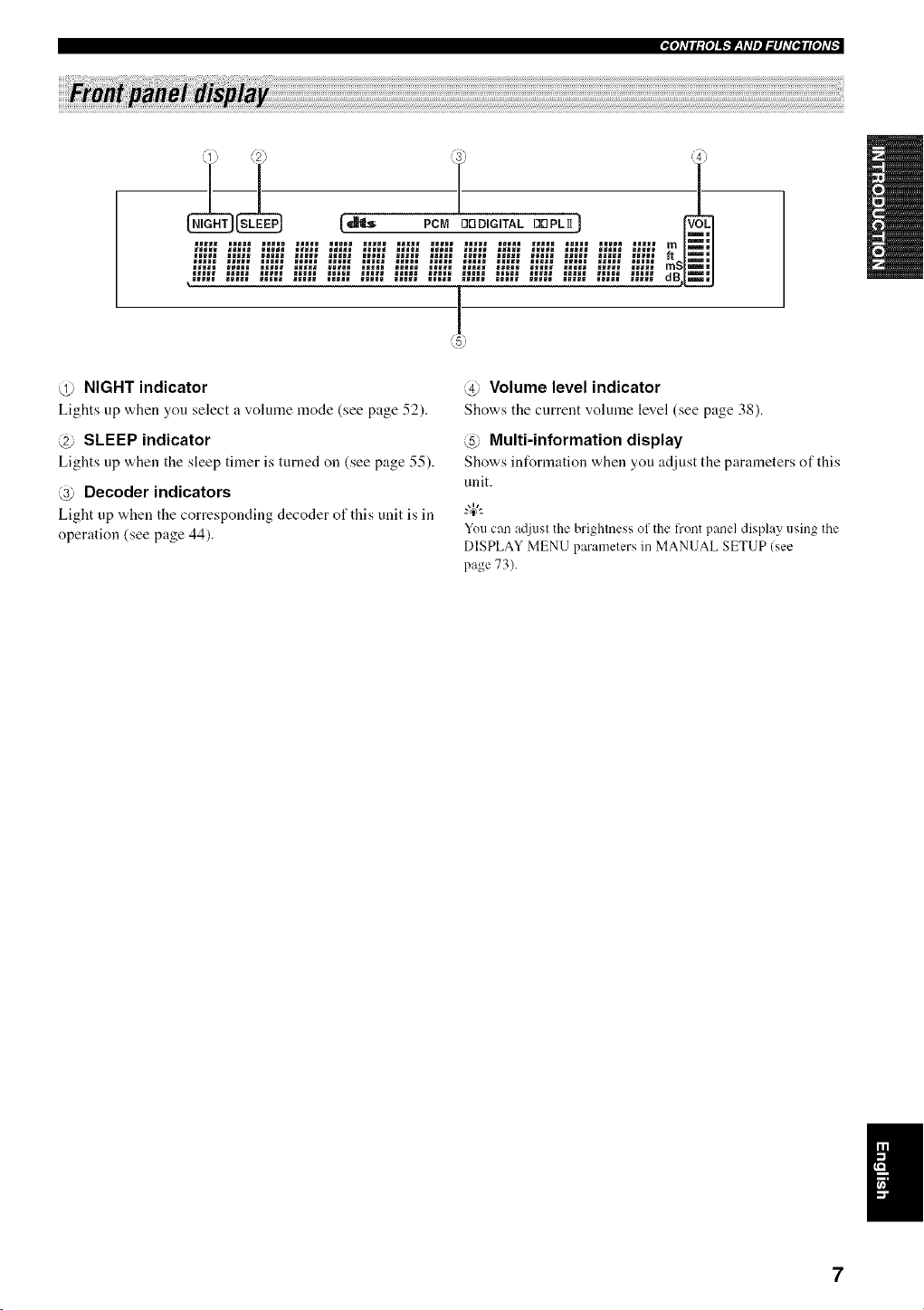
@ NIGHT indicator
Lights up when you select a volume mode (see page 52).
@ SLEEP indicator
Lights up when the sleep timer is turned on (see page 55).
@ Decoder indicators
Light up "a,hen the corresponding decoder of this unit is in
operation (see page 44).
@ Volume level indicator
Shows the current volume level (see page 38).
@ Multi-information display
Shows information when you adjust the parameters of this
unit.
You can atliust the brightness of the L'rontpanel display using the
DISPLAY MENU parameters in MANUAL SETUP (see
page 73).
K_e]_Vll;{e]_lF_f_Vel_lhV[e_Jl[e]_v_
/
VCR TV/STB SUBWOOFER VIDEO
--AUDIO INPUT-- --OUT
(U.S.A. and Canada models)
TV/STB AUX DVD SYSTEM
--OPTICAL-- COAXIAL CONNECTOR
DiGiTAL INPUT--
J
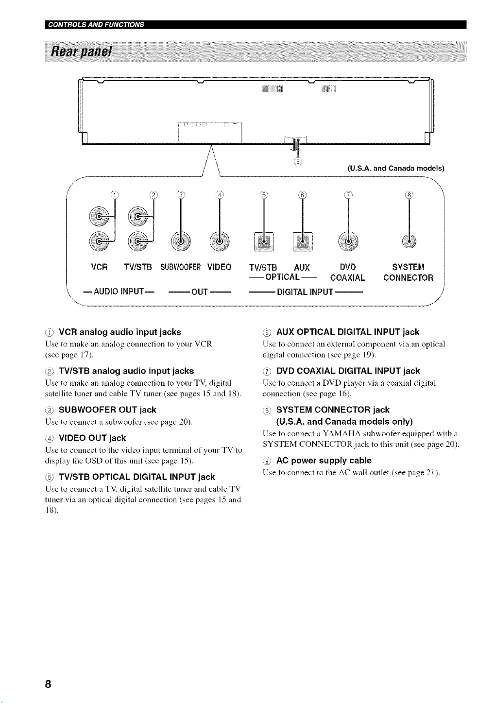
@ VCR analog audio input jacks
Use to make an analog connection to your VCR
(see page 17).
@ TV/STB analog audio input jacks
Use to make an :malog connection to your TV, digital
satellite tuner and cable TV tuner (see pages 15 and 18).
@ SUBWOOFER OUT jack
Use to connect a subwoofer (see page 20).
@ VIDEO OUT jack
Use to connect to the video input terminal of your TV to
display the OSD of this unit (see page 15).
@ TV/STB OPTICAL DIGITAL INPUT jack
Use to connect a TV, digital satellite tuner and cable TV
tuner via an optical digital connection (see pages 15 and
18).
@ AUX OPTICAL DIGITAL INPUT jack
Use to connect an external component via an optical
digital connection (see page 19).
@ DVD COAXIAL DIGITAL INPUT jack
Use to connect :t DVD player via a coaxial digital
connection (see page 16).
@ SYSTEM CONNECTOR jack
(U.S.A. and Canada models only)
Use to connect a YAMAHA subwoofer equipped with a
SYSTEM CONNECTOR jack to this unit (see page 20).
@ AC power supply cable
Use to connect to the AC "a,all outlet (see page 21 ).
Thissectiondescribestheflmctionofeachcontrolonthe
remotecontrolusedtocontrolthissystem.
"4¢--
You can also control other components using the remote control
once you set the appropriate remote control codes. See
"Controlling other components" on page 83 for details.
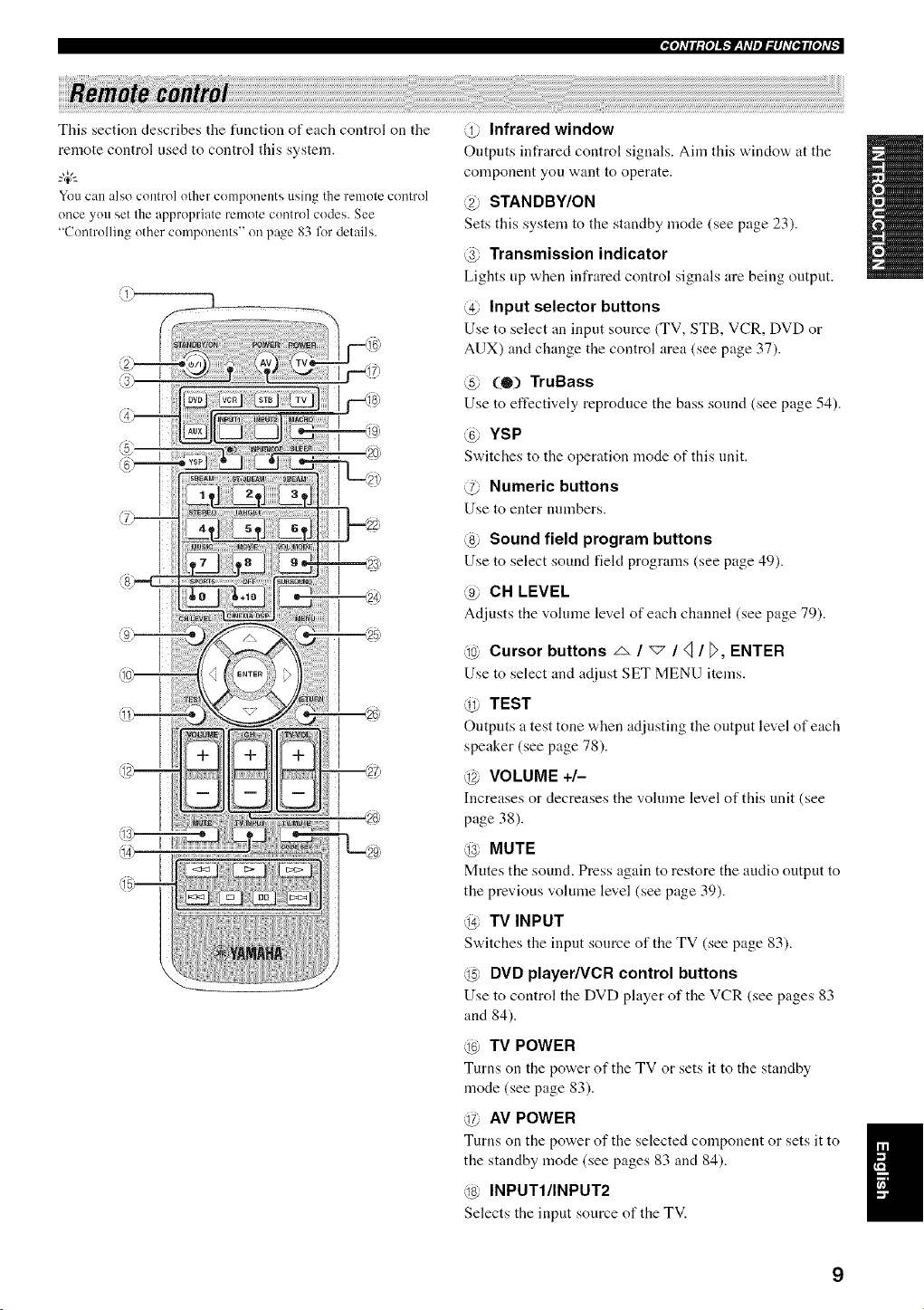
@ Infrared window
Outputs infrared control signals. Aim this window at the
component you want to operate.
@ STANDBY/ON
Sets this system to the standby mode (see page 23).
@ Transmission indicator
Lights up when infrared control signals are being output.
@ Input selector buttons
Use to select an input source (TV, STB, VCR, DVD or
AUX) and change the control area (see page 37).
@ (0) TruBass
Use to effectively reproduce the bass sound (see page 54).
YSP
S'a,itches to the operation mode of this unit.
@ Numeric buttons
Use to enter numbers.
@ Sound field program buttons
Use to select sound field programs (see page 49).
@ CH LEVEL
Adjusts the volume level of each channel (see page 79).
@ Cursor buttons _ / "_ / _ / D, ENTER
Use to select and adjust SET MENU items.
@ TEST
Outputs a test tone "a,hen adjnsting the output level of each
speaker (see page 78).
@ VOLUME +/-
Increasesor decreases the volume level of this unit (see
page 38).
MUTE
Mutes the sound. Press again to restore the audio output to
the previous volume level (see page 39).
@ TV INPUT
Sw,itches the input source of the TV (see page 83).
@ DVD player/VCR control buttons
Use to control the DVD phtyer of the VCR (see pages 83
and 84).
@ TV POWER
Turns on the pow, er of the TV or sets it to the standby
mode (see page 83).
@ AV POWER
Turns on the power of the selected component or sets it to 1
the standby mode (see pages 83 and 84).
al
@ INPUTI/INPUT2
Selects the input source of the TV.
@ MACRO
Use to set the TV macro (see page 85).
@ INPUTMODE
Switches between input modes (AUTO, DTS or
ANALOG). See page 37 for details.
@ SLEEP
Sets tile sleep timer (see page 55).
@ Beam mode buttons
Change tile beam mode settings (see page 40).
@ VOL MODE
Turns on or off the '<)lume modes (see page 52).
@ SURROUND
Selects the surround mode for playback (see page 44).
;_ MENU
Displays the setup menu on your TV monitor (see
pages 28, 57 and 64).
The DVD menu is displayed when DVD is selected as the input
source.
@ RETURN
Use to select sleep timer settings or return to the previous
SET MENU screen.
@ TV VOL +/-
Adjusts the volume level of the TV (see page 83).
@ CH +/-
Switches between channels of the TV or the VCR (see
pages 83 and 84).
@ TV MUTE, CODE SET
Mutes the audio output of the TV (see page 83).
Use to set up remote control codes (see page 82).
10
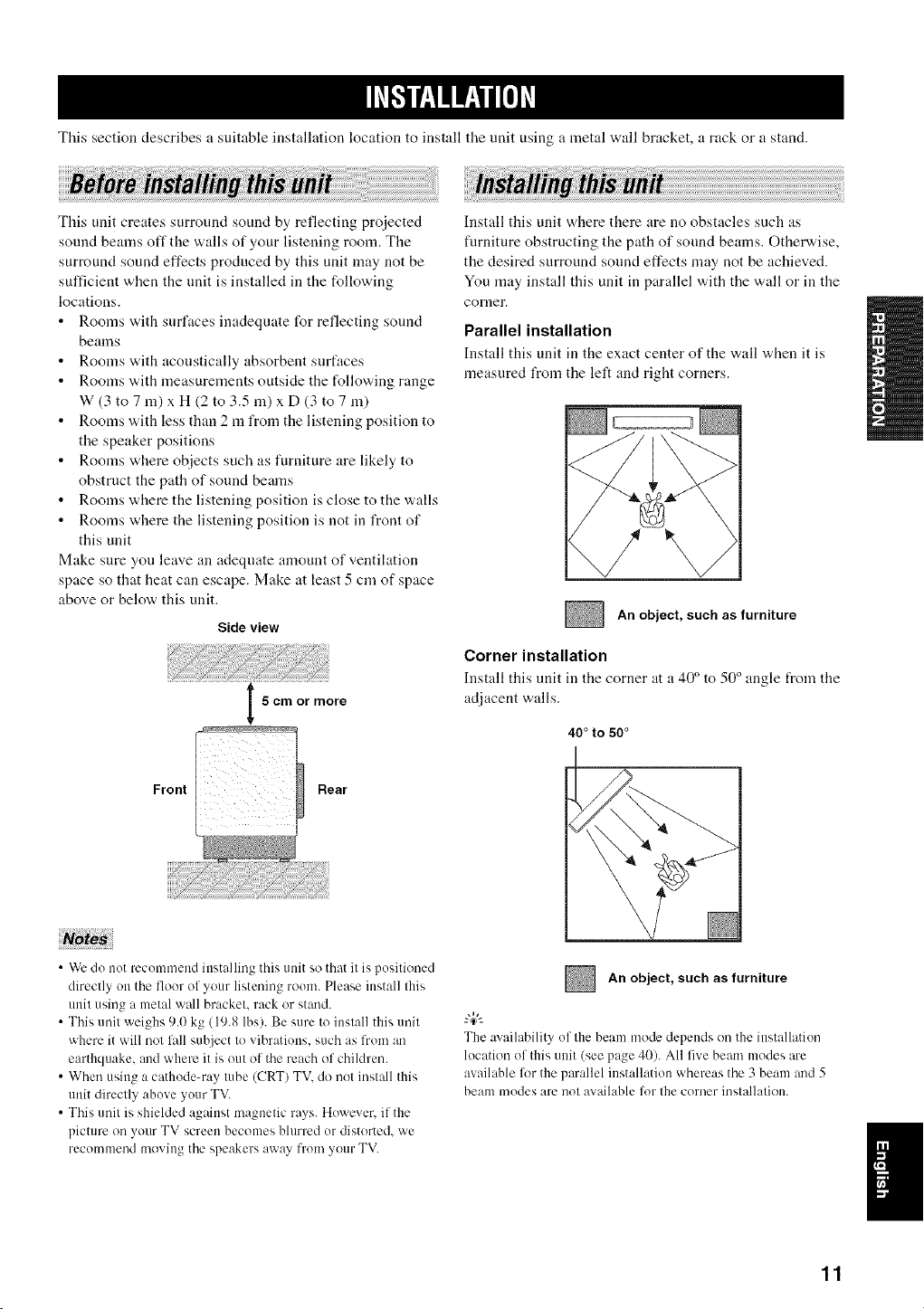
Tiffs section describes a suitable installation location to install the unit using a metal wall bracket, a rack or a stand.
This unit creates surround sound by reflecting pro]ected
sound beams off the walls of your listening worn. The
surround sound effects produced by this unit may not be
sufficient when the nnit is installed in the following
locations.
Rooms with surfaces inadequate for reflecting sound
beams
Rooms with acoustically absorbent surfaces
Rooms with measurements outside the following range
W (3 to 7 m) x H (2 to 3.5 m) x D (3 to 7 m)
Rooms with less than 2 m from the listening position to
the speaker positions
Rooms where objects such as furniture are likely to
obstruct the path of sound beams
Rooms where the listening position is close to the walls
Rooms where the listening position is not in front of
this unit
Make sure you leave an adeqnate amount of ventilation
space so that heat can escape. Make at least 5 cm of space
above or below this unit.
Side view
I 5cmormore
Rear
Front
Install this unit where there are no obstacles such as
furniture obstructing the path of sonnd beams. Otherwise,
the desired surronnd sound effects may not be achieved.
You may install this unit in parallel with the wall or in the
corner.
Parallel installation
Install this unit ill tile exact center of the w,all when it is
measured from the left and right corners.
An object, such as furniture
Corner installation
Install this unit in the corner at a 40 ° to 50 ° angle t_om tile
adjacent walls.
40 ° to 50°
• Wc do not recommend installing this unit so that it is positioned
directly on the flour of your listening room. Please install this
unit using a metal wall bracket, rack or stand.
• This unit weighs 9.0 kg (19.8 lbs). Be sure to install this unit
where it will not lall suhject to vibratiuns, such as from an
earthquake, and where it is out of the reach of children.
• When using a cathode-ray tube (CRT) TV. do not install this
unit directly abuve your TV.
• This unit is shielded against magnetic rays. Huwever. if the
picture on your TV screen becomes blurred ur distorted, we
recommend moving the speakers away from your TV.
An object, such as furniture
The availability of the beam mode depends on the installation
lucation of this unit (see page 40). All five beam modes are
available for the parallel installation whereas the 3 beam and 5
beam modes are not available lor the curner installation.
11
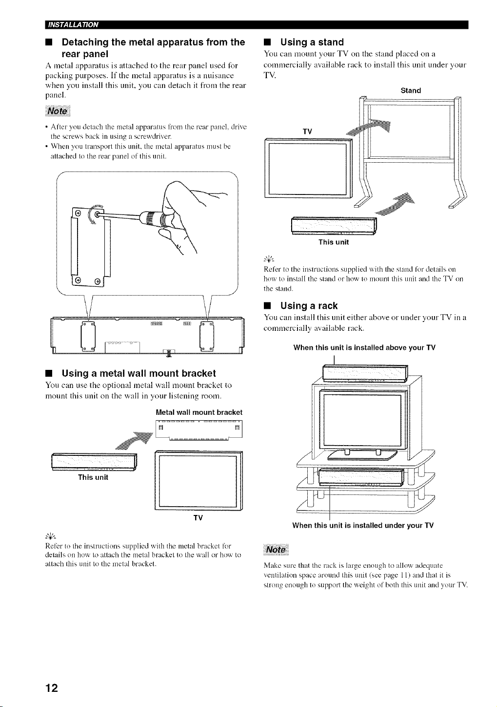
• Detaching the metal apparatus from the
rear panel
A metal apparatus is attached to the rear panel used for
packing purposes. If the metal apparatus is a nuisance
when you install this unit, you can detach it from the rear
panel.
• Using astand
You can mount your TV on the stand placed on a
connnercially available rack to install this unit under your
TV.
Stand
• After you detach the metal apparatus li'om the rear panel, drive
the screws back in using a screwdriver.
• When you transport this unit. the metal apparatus must be
attached to the rear panel of this unit.
• Using a metal wall mount bracket
You can use the optional metal wall mount bracket to
mount this unit on the wall in your listening room.
Metal wall mount bracket
This unit
TV
1
Relcr to the instructions supplied with the metal bracket for
details on how to attach the metal bracket to the wall or how to
attach this unit tu the metal bracket.
TV
This unit
Refer to the instructions supplied with the stand lbr details on
how to install the stand or how to mount this unit and the TV on
the stand.
• Using a rack
You can install this unit either above or under your TV in a
commercially available rack.
When this unit is installed above your TV
When this unit is installed under your IV
Make sure that the rack is large enough tu alluw adequate
venlilation space arotmd this unit (see page 11) and thai it is
glrUllg enuugh Io suppurt the weight of bolh Ihis Ullit alld your TV.
12
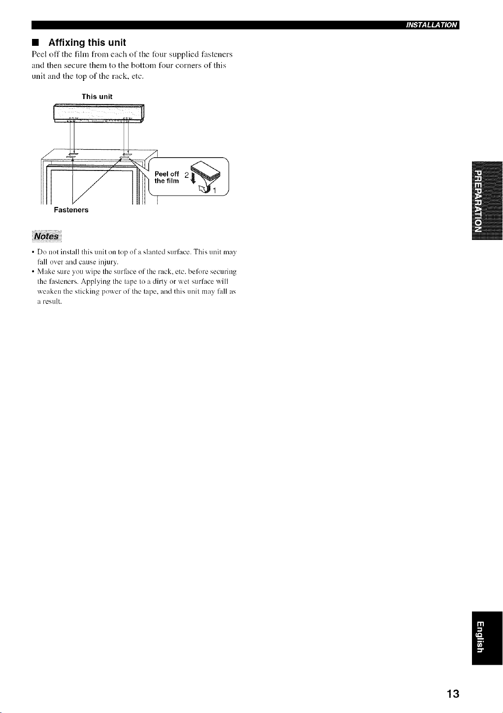
• Affixing this unit
Peel off the fihn from each of the four supplied fasteners
and then secure them to the bottom four corners of this
unit and the top of the rack, etc.
This unit
Fasteners
• Do not install this unit on top of a slanted surface. This unit may
lhll over and cause iI_iury.
• Make sure you wipe the surface of the rack. etc. before securing
the lhsteners. Applying the tape to a dirty or wet surlhce will
weaken the sticking power of the tape. and this unit may fall as
a restllt.
13
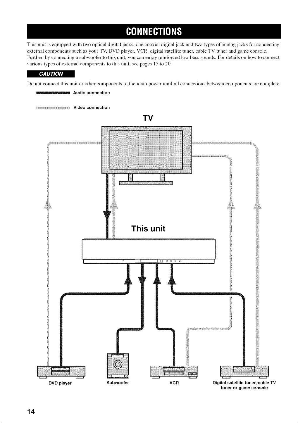
This unit is equipped with two optical digital jacks, one coaxial digital jack and two types of analog jacks for connecting
external components such as your TV, DVD player, VCR, digital satellite tuner, cable TV tuner and game console.
Further, by connecting a subwoofer to this unit, you can enjoy reinforced low bass sounds. For details on how to connect
various types of external components to this unit, see pages 15 to 20.
[_: lIj/roJAv|
Do not connect this unit or other components to the main power until all connections between components are complete.
Audio connection
Video connection
TV
This unit
DVD player Subwoofer VCR Digital satellite tuner, cable TV
tuner or game console
14
('h'hT_(?h'f
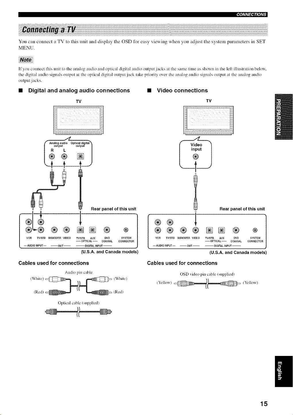
You can connect a TV to this unit and display the OSD for easy viewing when you adjust the system parameters in SET
MENU.
11you connect this unit to the analog audio and optical digital audio outpul jacks at the same time as shown irathe left illustration below,
the digital audio signals output at Ille optical digital output jack lake priorily over the analog audio signals oulput at the analog audio
output jacks.
• Digital and analog audio connections • Video connections
TV
)
Rear panel of this unit
o;o
(U.S.A. and Canada models)
TV
l Rear panel of this unit
m
®® ®® NN ® ®
VCR TWSTB SUBN00FER VIDEO TV/STB AUX DVD SYSTEM
--OPTICAL-- COAXIAL CONNECTOR
-- AUDIO INPUT-- -- OUT -- -- DIGITAL INPUT-
{U.S.A. and Canada models)
Cables used for connections Cables used for connections
Audio pin cable
(Red) /Red)
OSD video pin cable lsupplied/
/Yellow) !Yellow)
Oplical cable (supplied/
15
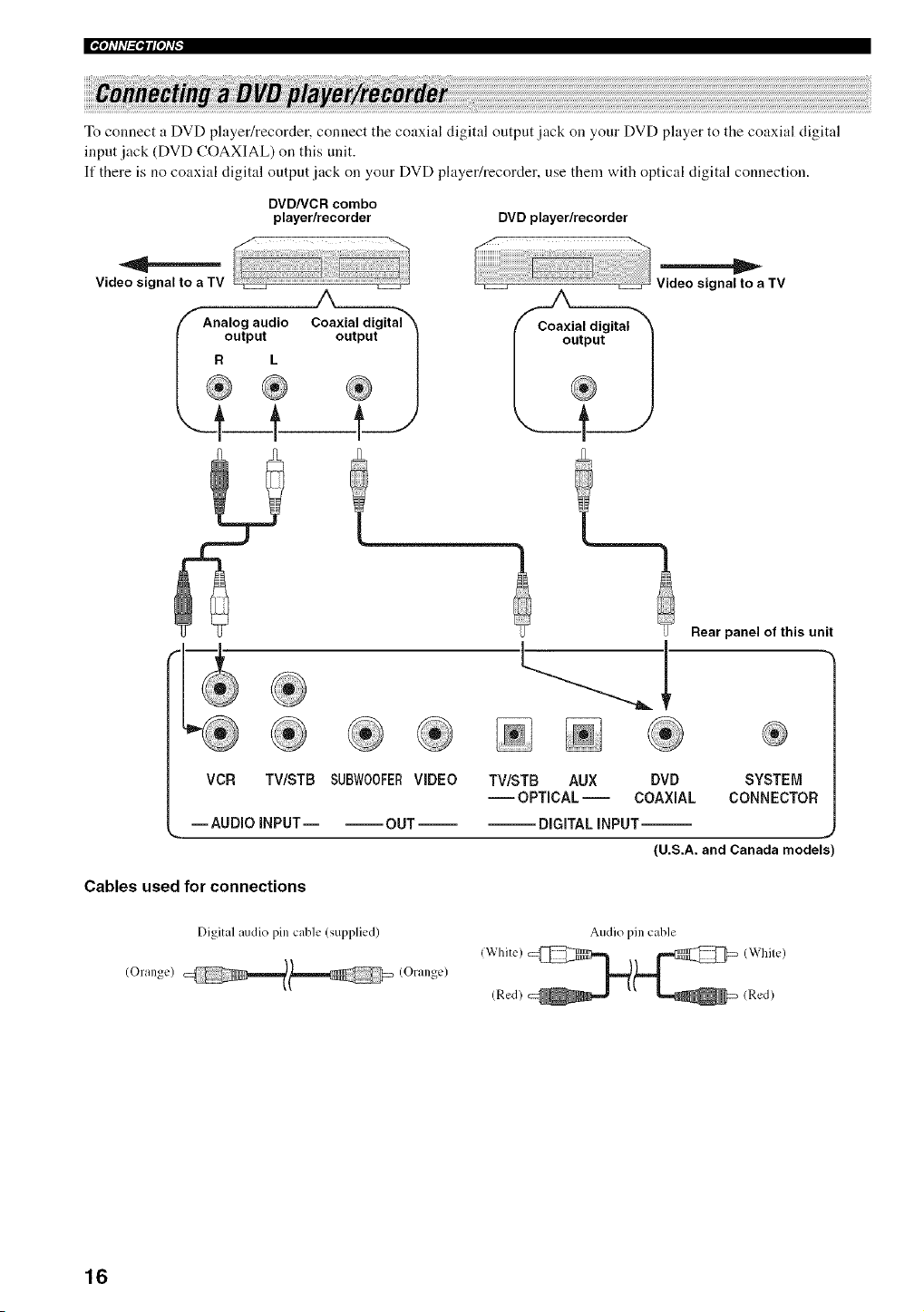
|_qllll_tIPh'_
To connect a DVD player/recorder, connect the coaxial digital output jack on your DVD player to the coaxial digital
input jack (DVD COAXIAL) on this unit.
If there is no coaxial digital output jack on your DVD player/recorder, use them with optical digital connection.
DVD/VCR combo
player/recorder
Video signal to a TV
A
Analog audio
R_°utput
DVD player/recorder
Rear panel of this unit
Coaxial digital X Coaxial digital
o7/
Video signal to a TV
VCR TV/STB SUE}W00FERVIDEO TV/STB AUX DVD SYSTEM
-- OPTICAL -- COAXIAL CONNECTOR
--AUDIO INPUT-- --OUT DiGiTAL INPUT--
(U.S.A. and Canada models'
Cables used for connections
Digital audio pin cable (supplied)
(Orange) (Orange)
Audio pin cable
(Red) (Red)
16
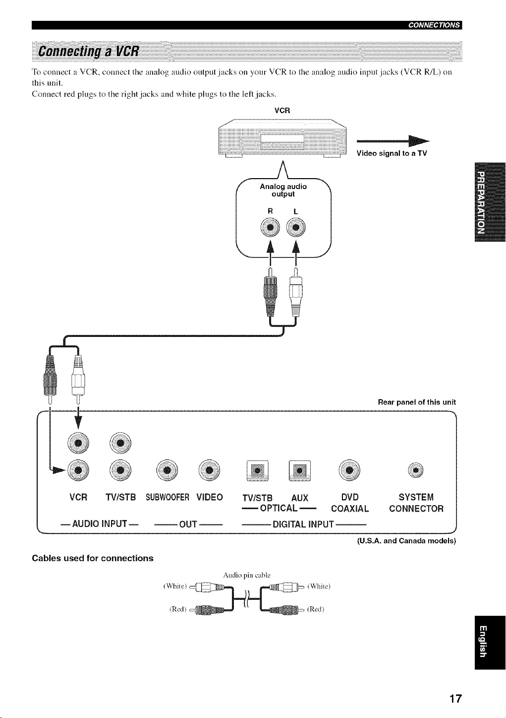
_qlTIT_l?IIf
To connect a VCR, connect the analog audio output jacks on your VCR to the analog audio input jacks (VCR R/L) on
this unit.
Connect red plugs to the right jacks and white plugs to the left jacks.
VCR
Video signal to a TV
Rear panel of this unit
VCR TV/STB SUBWOOFER VIDEO
--AUDIO iNPUT OUT
Cables used for connections
TV/STB AUX DVD
OPTICAL = COAXIAL
SYSTEM
CONNECTOR
DiGiTAL INPUT--
,,J
(U.S.A. and Canada models)
Audio pin cable
17
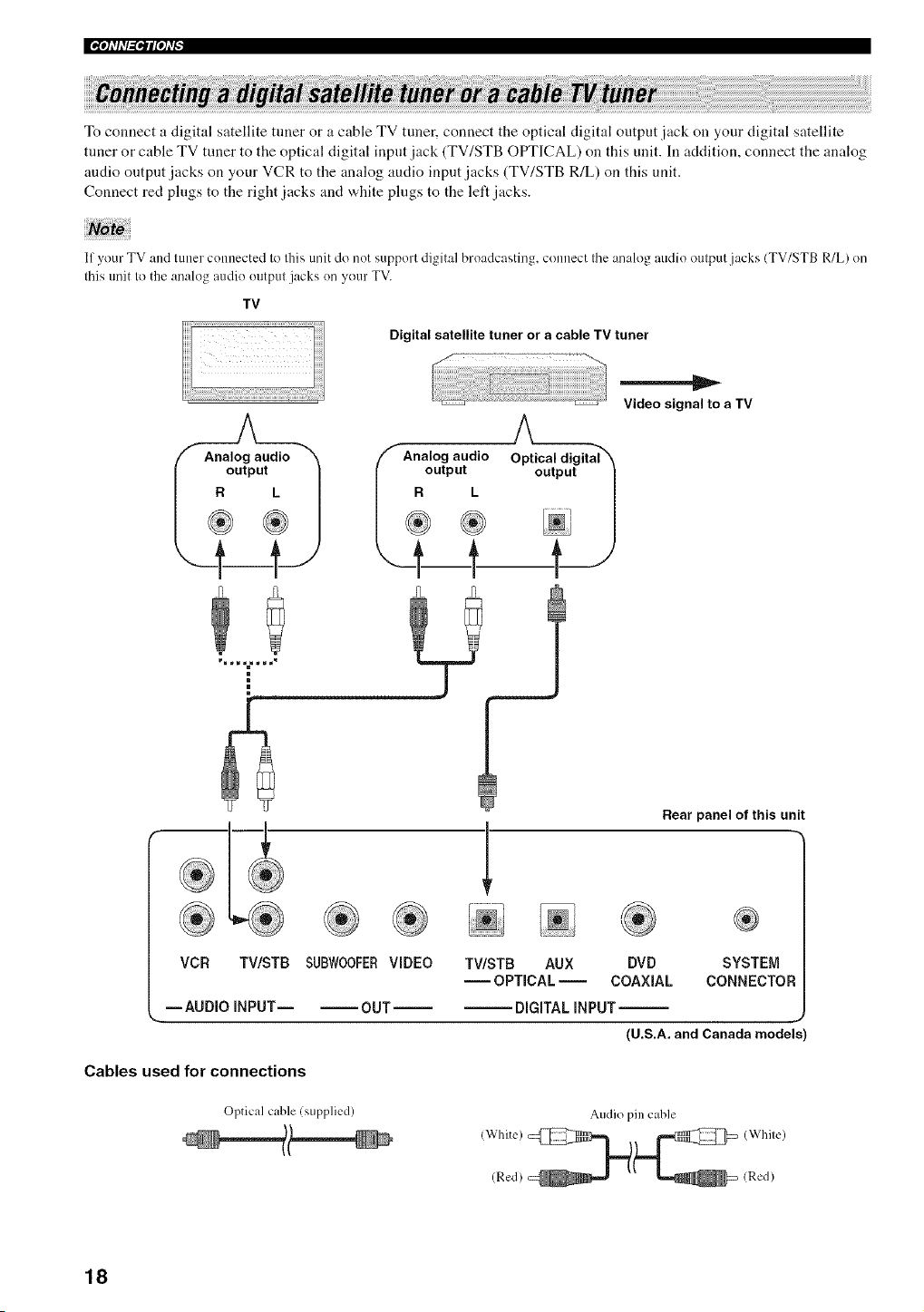
To connect a digital satellite tuner or a cable TV tuner, connect the optical digital output jack on your digital satellite
tuner or cable TV tuner to the optical digital input jack (TV/STB OPTICAL) on this unit. In addition, connect the analog
audio outpnt jacks on your VCR to the analog audio input jacks (TV/STB R/L) on this unit.
Connect red plugs to the right jacks and white plugs to the left jacks.
I1 your TV and tuner connected Io Ihis unit do not support digital broadcasting, connect Ihe analog audio oulput jacks (TV/STB R/L) on
Ihis unit Io the analog audio outpul jacks on your TV.
TV
Digital satellite tuner or a cable TV tuner
'f" Analog audio
output
® ®
Video signal to a TV
®
Rear panel of this unit
VCR TV/STB SUBWOOFERVIDEO
-- AUDIO INPUT OUT
TV/STB AUX DVD SYSTEM
-- OPTICAL -- COAXIAL CONNECTOR
DIGITAL INPUT--
J
(U.S.A. and Canada models
Cables used for connections
Optical cable (supplied)
Audio pin cable
(Red) (Red)
18
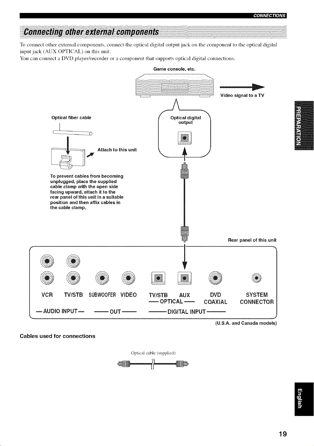
_'tl'h'l_lP'tff
To connect other external components, connect the optical digital output lack on the component to the optical digital
input jack (AUX OPTICAL) on this unit.
You call connect a DVD player/recorder or a component that supports optical digital connections.
Game console, etc.
Video signal to a TV
Optical(__1fiber cable_ _, OptiCaloutputdigital1
__ Attach to this unit
_' n
To prevent cables from becoming
unplugged, place the supplied
cable clamp with the open side
facing upward, attach it to the
rear panel of this unit in a suitable
position and then affix cables in
the cable clamp.
Rear panel of this unit
VCR TWSTB SUBW00FERVIDEO TV/STB AUX DVD SYSTEM
-- OPTICAL -- COAXIAL CONNECTOF
--AUDIO INPUT OUT DIGITAL iNPUT--
(U.S.A. and Canada models
Cables used for connections
Oplical cable (supplied)
19
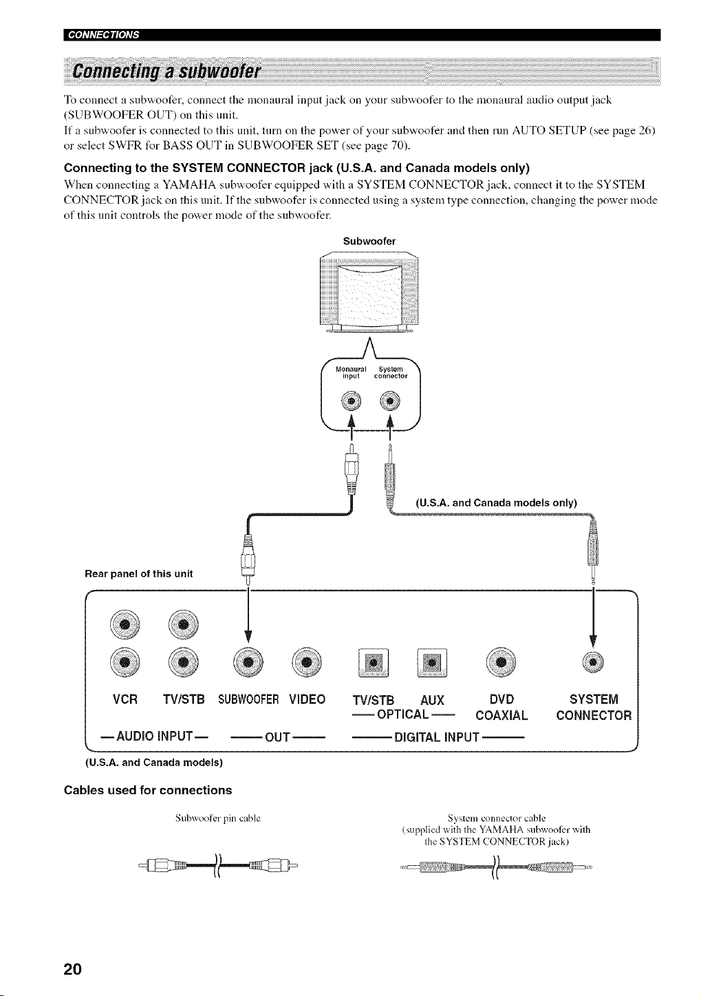
|'_"tlll'l_ql["tl'_
To connect a subwoofer, connect the monaural input jack on your stlbwoofer to the monaural audio output jack
(SUBWOOFER OUT) on this unit.
If a subwoofer is connected to this unit, turn on the power of your subwoofer and then run AUTO SETUP (see page 26)
or select SWFR for BASS OUT in SUBWOOFER SET (see page 70).
Connecting to the SYSTEM CONNECTOR jack (U.S.A. and Canada models only)
When connecting a YAMAHA subwoofer equipped with a SYSTEM CONNECTOR jack, connect it to the SYSTEM
CONNECTOR jack on this unit. If the snbwoofer is connected using a system type connection, changing the power mode
of this unit controls the power mode of the subwoofer.
Subwoofer
Rear panel of this unit
®® 1
® ® ® ® ® ® ® ®
(U.S.A. and Canada models)
Cables used for connections
Subwoofcr pin cable System connector c_hle
(supplied with the YAMAHA subwooli:r with
the SYSTEM CONNECTOR jack)
20
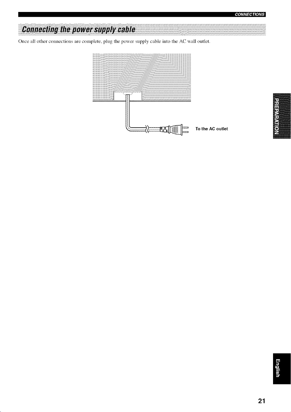
Pti'li'l'_l_qff
Once all other connections are complete, plug the power supply cable into the AC wall outlet.
To the AC outlet
21
®
'i'i'i ill
....
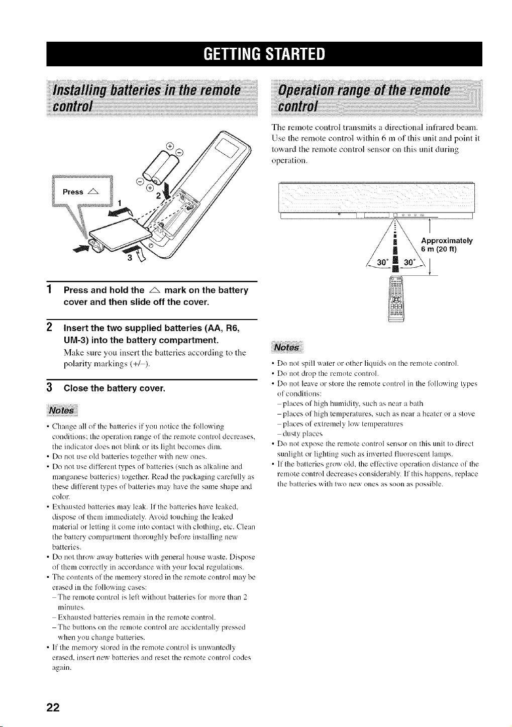
The remote control transmits a directional infrared beam.
Use the remote control within 6 m of this unit and point it
toward the remote control sensor on this unit during
operation.
Press and hold the _ mark on the battery
cover and then slide off the cover.
Insert the two supplied batteries (AA, R6,
UM-3) into the battery compartment.
Make sure you insert tile batteries according to tile
polarity markings (+/).
3 CIosethe battery cover.
• Change all of the batteries if you notice the following
conditions: the operation range uf the rmnote contrul decreases.
the indicator does nut blink or its light becumes dim.
• Do not use old batteries together with new ones.
• Do not use different types uf batteries (such as alkaline and
manganese batteries) together. Read the packaging carelully as
these dilTerent types of batteries may have the same shape and
cu]or.
• Exhausted batteries may leak. If the batteries hme leaked,
dispose of them in)mediately. Avoid touching the leaked
material ur letting it come into contact with clothing, etc. Clean
the battery compartment thoroughly belore installing new
batteries.
• Do nut throw away batteries with general house waste. Dispuse
of them correctly in accurdance with your local regulations.
• The contents uf the memury stored in the remote cuntrol may be
erased in the folluwing cases:
The remote control is lelt without batteries lor more that) 2
minutes.
Exhausted batteries remain in the remote controh
The buttons on the remote contrul are acckleutally pressed
when you change batteries.
• If the mmnory stored in the rmnote cuntrol is unwantedly
erased, insert uew batteries and reset the rmnote CUlltru]codes
again.
• Du not spill water or other liquids on the remote controh
• Du not drop the remute controh
• Do not leave or store the remote control in the lbllowing types
of conditions:
places uf high humidity, such as near a bath
places of high temperatures, such as near a heater or a stove
places of extremely low temperatures
dusty places
• Do not expose the remote control sensor on this unit to direct
sunlight or lighting such as i)werted fluorescent lamps.
• If the batteries grow old, the effective operation distance of the
remote control decreases considerably. If this happens, replace
the batteries with twu new ones as suon as possible.
22
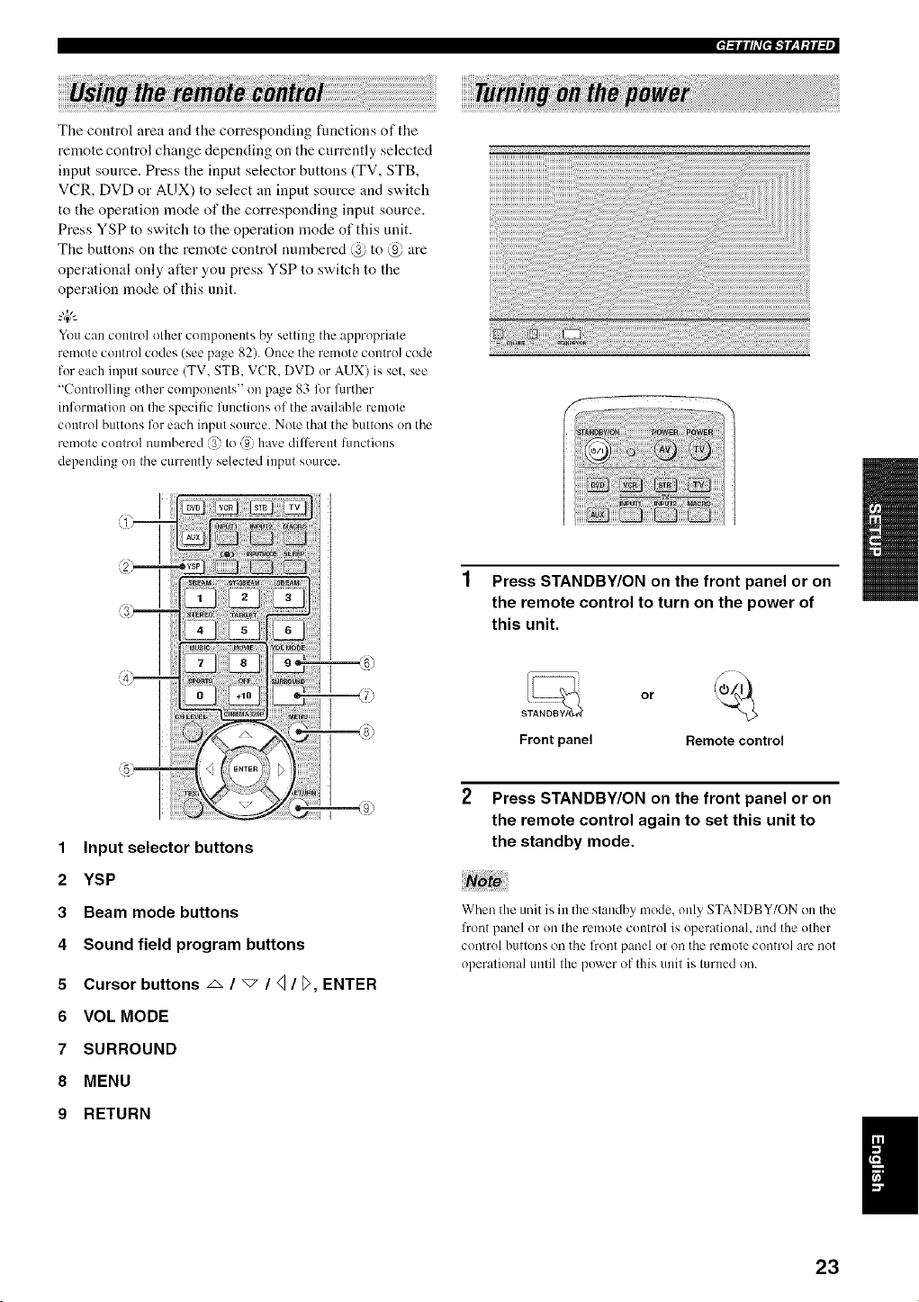
The control area and the corresponding functions of the
remote control change depending on the currently selected
input source. Press the input selector buttons (TV, STB,
VCR, DVD or AUX) to select an input source and switch
to the operation mode of the corresponding input source.
Press YSP to switch to the operation mode of this unit.
The buttons on the remote control numbered @ to @ are
operational only after you press YSP to switch to the
operation mode of this unit.
"4_':
You can control other componeuts by setting the appropriate
remote control codes (see page 82). Once the remote control code
for each input source (TV, STB, VCR, DVD or AUX) is set, see
"Controlling other components" on p:_ge 83 %r further
information on the specific functions of the :wailable remote
control buttons lor each input source. Note that the buttons on the
rmnote control numbered @ to _{ h:_xe diltcrent Rmctions
depending on the currently selected input source.
1 Press STANDBY/ON on the front panel or on
the remote control to turn on the power of
this unit.
or
S
Front panel Remote control
1 Input selector buttons
2 YSP
3 Beam mode buttons
4 Sound field program buttons
5 Cursor buttons _ / _ / _/_>, ENTER
6 VOL MODE
7 SURROUND
8 MENU
9 RETURN
2 Press STANDBY/ON on the front panel or on
the remote control again to set this unit to
the standby mode.
Note
When the unit is in the standby mode, only STANDBY/ON on the
l?ont panel or on the remote control is operational, and the other
control buttons oil the frout panel or oil the remote control are uot
operational until the power of this unit is turned on.
23
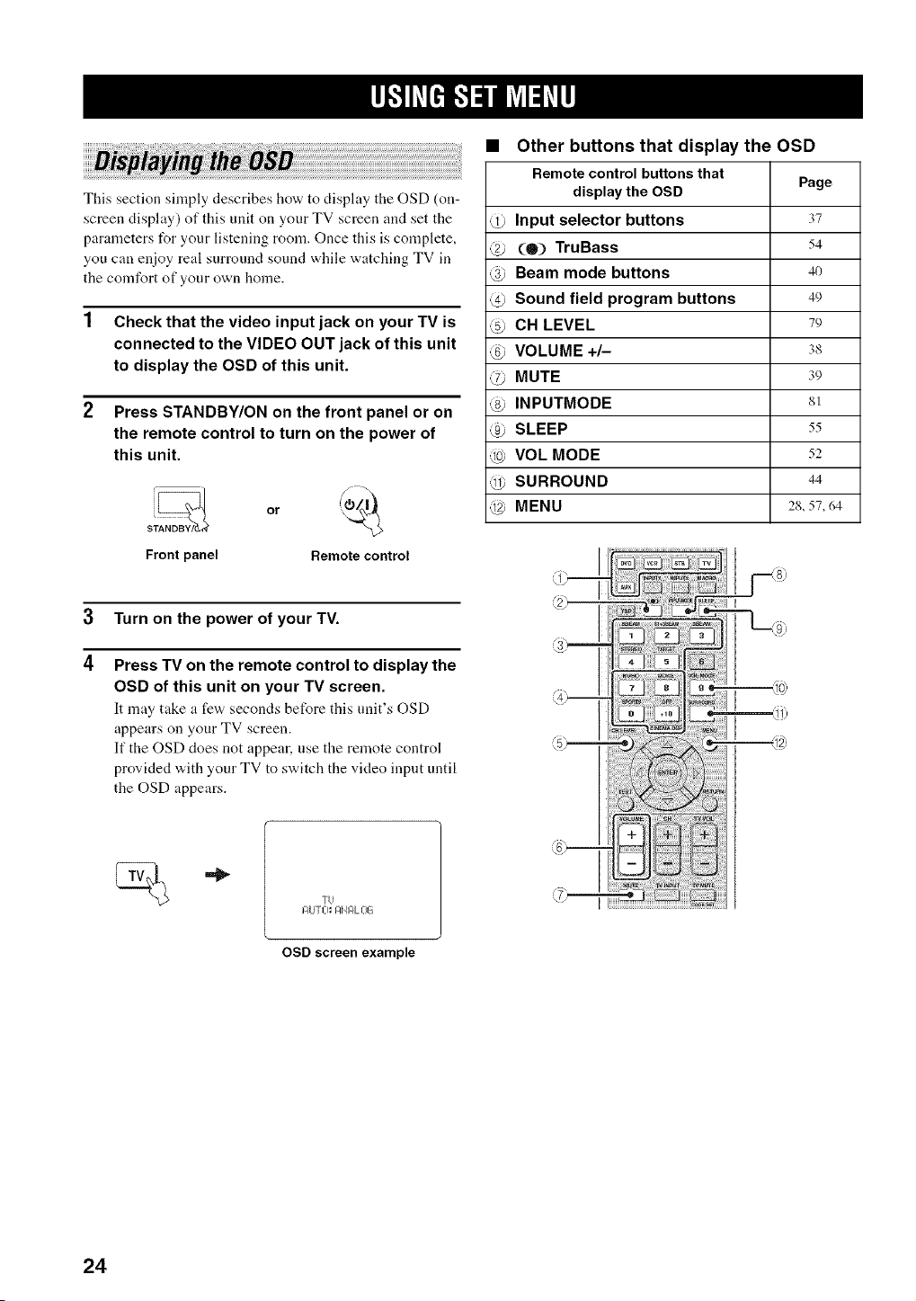
This section simply describes how to display the OSD (on-
screen display) of this unit on your TV screen and set the
parameters for your listening room. Once this is complete,
you can enjoy real surround sound while watching TV in
the comfort of your own home.
1 Check that the video input jack on your TV is
connected to the VIDEO OUT jack of this unit
to display the OSD of this unit.
2 Press STANDBY/ON on the front panel or on
the remote control to turn on the power of
this unit.
Front panel Remote control
3 Turn on the power of your TV.
4
Press TV on the remote control to display the
OSD of this unit on your TV screen.
It may take a few seconds before this unit's OSD
appears on your TV screen.
If the OSD does not appear, use the remote control
provided with your TV to switch the video input until
the OSD appears.
• Other buttons that display the OSD
Remote control buttonsthat
display the OSD Page
@ Input selector buttons 37
@ (O) TruBass 54
4) Beam mode buttons 4o
@ Sound field program buttons 49
@ CH LEVEL 79
@ VOLUME +/- 3s
@ MUTE 39
@ INPUTMODE 81
@ SLEEP 55
@ VOL MODE 52
@ SURROUND 44
@ MENU 2s, 57, 64
IZIU T L-I_ I:IN F4L013
OSD screen example
24
r_-'lffl,'f-'l--illi_l-_fl,
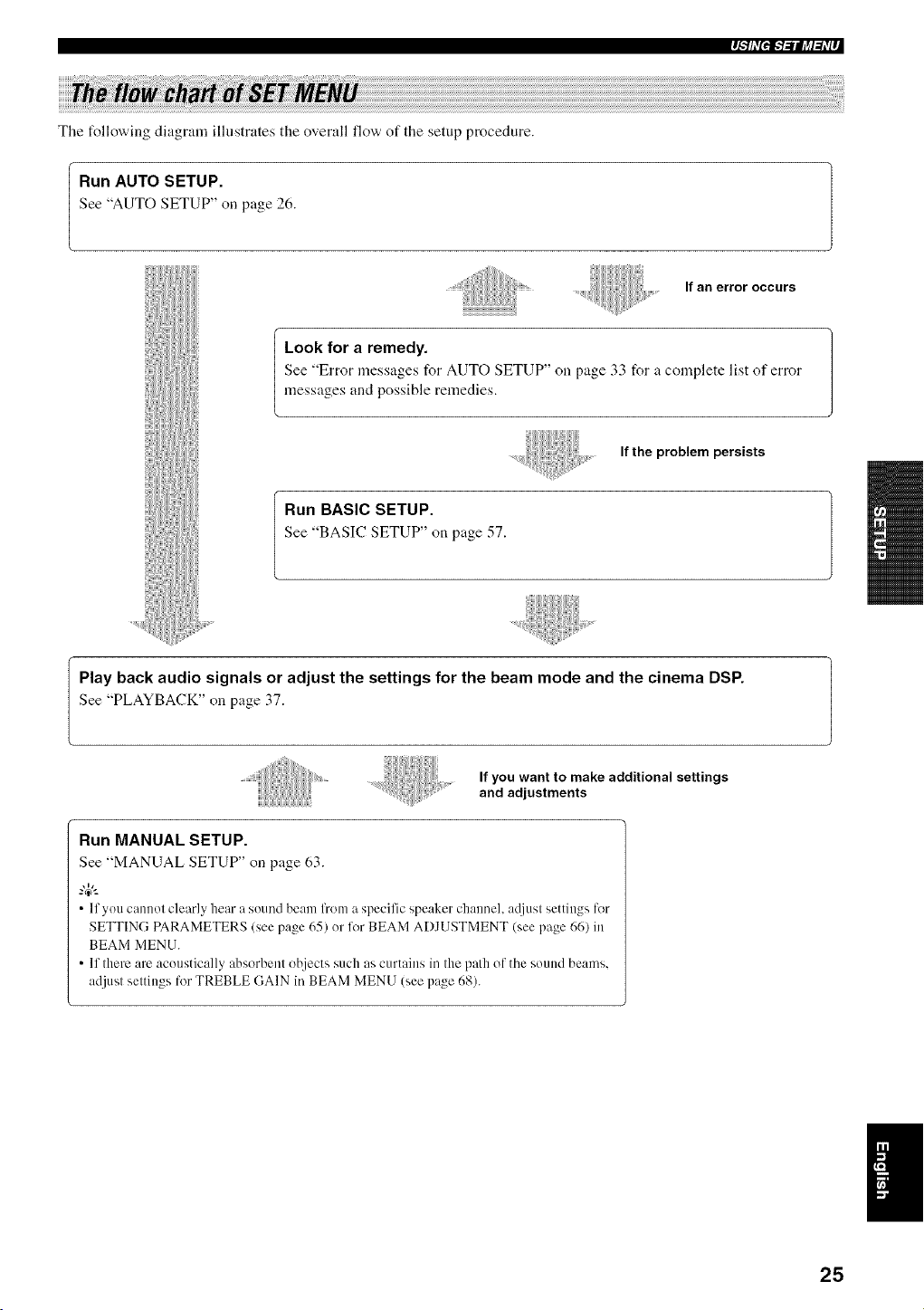
The t_llowing diagram ilhistrates the overall flow' of the setup procedure.
Run AUTO SETUP.
See "AUTO SETUP" oil p_ge 26.
If an error occurs
Look for a remedy.
See "Error messages for AUTO SETUP" on page 33 for _ complete list of error
messages and possible remedies.
If the problem persists
Run BASIC SETUP.
See "BASIC SETUP" on p_ge 57.
I Play back audio signals or adjust the settings for the beam mode and the cinema DSP.
See "PLAYBACK" on page 37.
If you want to make additional settings
and adjustments
Run MANUAL SETUP.
See "MANUAL SETUP" on p_ge 63.
• If you cannot clearly hear a sound beam from a specific speaker chaimel, ac[iust settings l(,r
SETTING PARAMETERS (see page 65) or li,r BEAM ADJUSTMENT (see page 66) in
BEAM MENU.
• If there are acoustically _bsorbent ot_iects such as curtains in the path of the sound beams.
adjust settings for TREBLE (IAIN in BEAM MENU (see pz_ge68).
25
This unit creates a sound field by reflecting sound beams on the walls of your listening room and broadening the
cohesion between speaker channels. Just as you would arrange the speaker position of other audio systems, you need to
set the beam angle to enjoy the best possible sound from this unit.
This unit employs the beam optimization feature and the YAMAHA Parametric Room Acoustic Optimizer (YPAO)
technology with the aid of the supplied optimizer microphone, allowing you to avoid troublesome listening-based
speaker setup and achieving highly accurate sound adjustments that best match your listening environment.
The beam optimization is the automated feature of BASIC SETUP, which creates the best possible surround sound fiekt
without manually setting the parameters for your listening room.
The YAMAHA Parametric Room Aconstic Optimizer (YPAO) technology performs the following checks and
automatically makes appropriate sound adjustments.
DISTANCE:
Checks the phase and the distance of each beam from this unit and adjusts the delay of each channel so that each sound
beam reaches the listening position at the same time.
EQUALIZING:
Adjusts frequency and levels of each channel's parametric equalizer to reduce coloration across the channels and create a
cohesive sound field. YPAO equalizing calibration incorporates three parameters (frequency, level and Q factor) for each
of the seven bands in its parametric equalizer to provide highly precise automatic adjustment of frequency characteristics.
LEVEL:
Checks and adjusts the sound output level of each channel.
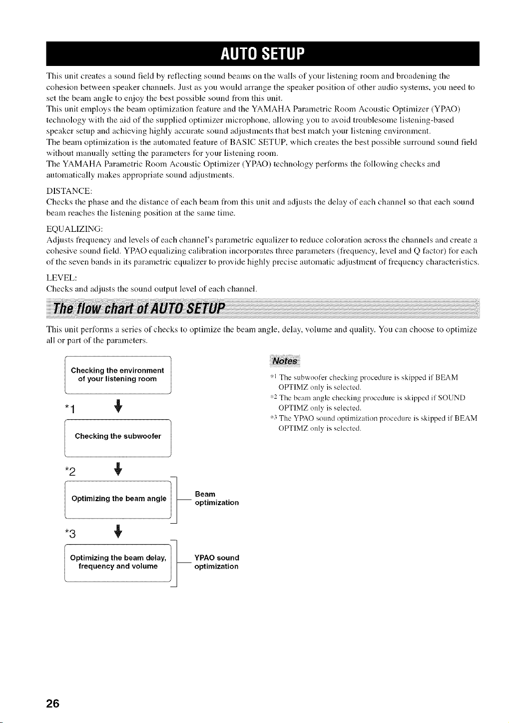
This unit performs a series of checks to optimize the beam angle, delay, volume and quality. You can choose to optimize
all or part of the parameters.
Checking the environment |
of yourlisteningroom
J
Checking the subwoofer
,:,1The subwoofer checking procedure is skipped if BEAM
OPTIMZ only is selected.
,:,2The beam angle checking procedure is skipped if SOUND
OPTIMZ only is selected.
,:,3The YPAO sound optimization procedure is skipped if BEAM
OPTIMZ only is selected.
1_ Beam
Optimizing the beam angle i i optimization
Optimizing the beam delay,
frequencyandvolume
]_ PAO sound
optimization
26
,llip_Fb-ilq +
The supplied optimizer microphone collects and analyzes the sound that this unit produces in your actual listening
environment. Follow the procedure below to connect the optimizer microphone to this unit and make sure that the
optimizer microphone is placed in a proper location and that there are no large obstacles between the optimizer
microphone and the walls in your listening room.
• Alter you have completed the AUTO SETUP procedure, be sure to disconnect the optimizer microphone.
• The optimizer microphone is sensitive to heat.
Keep it away li+omdirect sunlight+
Do not place it on top of this unit+
• Do not connect the optimizer microphone to an extension cable as doing so may result in an inaccurate sound optimization.
• An error may occur during the AUTO SETUP procedure if the optimizer microphone is not properly placed in your listening room. To
avoid the possibility of an error:
Do not place the optimizer microphone to the extrmne right or lelt l?om the center of this unit.
Do not place the optimizer microphone within 2 m from the front of this unit.
Do not place the optimizer microphone more than 1 m from the center height of this unit.
• Make sure that there are no obstacles bep,veen the optimizer microphone and the walls in your listening room as these objects obstruct
the path of sound beams. However, any ohjects that are in contact with the walls will be regarded as a protruding part of the walls.
• The best possible results are achieved if the optimizer microphone is placed at the same height as your ears would be when you are
seated in your listening position. However. if this is not possible, you can manually fine-tune the sound beam angle and balance the
sound beam output levels using MANUAL SETUP (see page 63) once the AUTO SETUP procedure is completed.
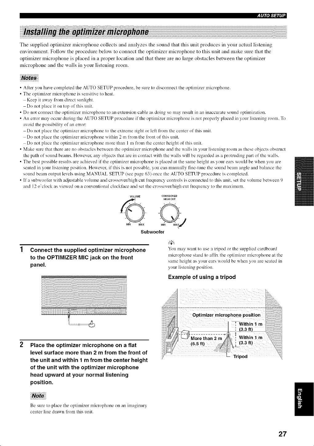
• If a subwoofer with a@lstable volume and crossover/high cut frequency controls is connected to this unit. set the volume between 9
and 12 o'clock as viewed on a conventional clocklace and set the crossover/high cut frequency to the maximum.
VOLUME CROSSOVER
Subwoofer
Connect the supplied optimizer microphone
to the OPTIMIZER MIC jack on the front
panel.
You may want to use a tripod or the supplied cardboard
microphone stand to affix the optimizer microphone at the
same height as your ears would be when you are seated in
your listening position.
Example of using a tripod
Place the optimizer microphone on a flat
level surface more than 2 m from the front of
the unit and within 1 m from the center height
of the unit with the optimizer microphone
head upward at your normal listening
position.
Be sure to place the optimizer microphone on an imaginary
center line drawn from this unit.
Optimizer microphone position
* Within 1 m
m-ggii,;2,-2--
(63 It) I'
L Tripod
27
l_lql'l-1-'illl +
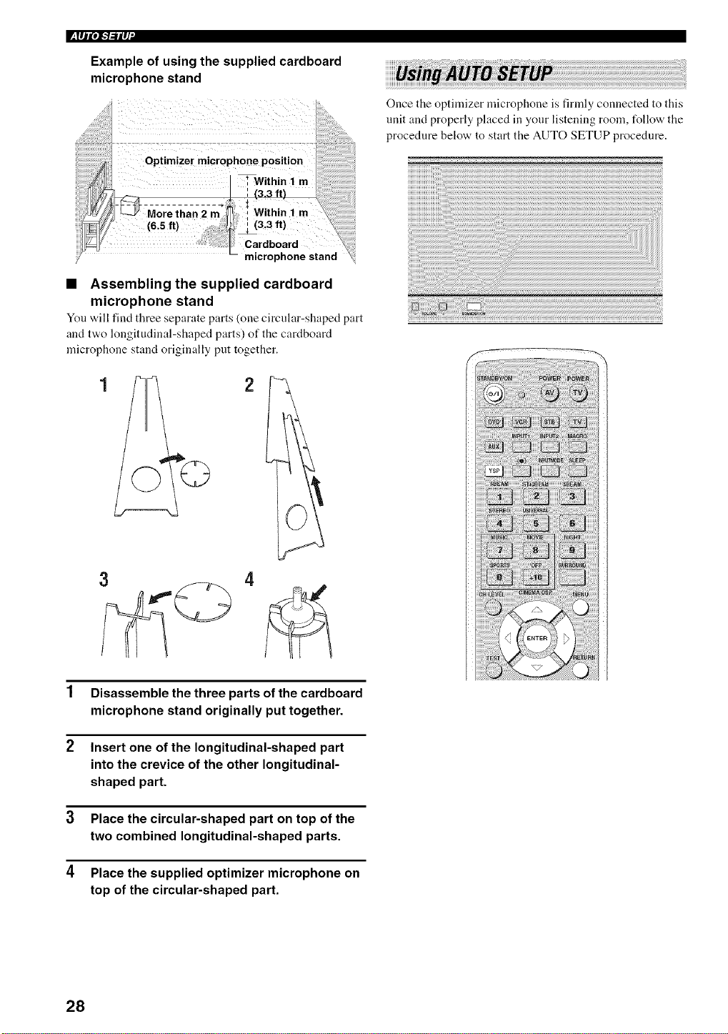
Example of using the supplied cardboard
microphone stand
Once the optimizer microphone is firmly connected to this
unit and properly placed in your listening room, tUllow the
procedure below to start the AUTO SETUP procedure.
• Assembling the supplied cardboard
microphone stand
You w,ill find three separate parts (one circular-shaped part
and two longitudinal-shaped parts) of the cardboard
microphone stand originally put together.
1 Disassemble the three parts of the cardboard
microphone stand originally put together.
2 Insert one of the longitudinal-shaped part
into the crevice of the other longitudinal-
shaped part.
3 Place the circular-shaped part on top of the
two combined longitudinal-shaped parts.
4 Place the supplied optimizer microphone on
top of the circular-shaped part.
28
,I111",I-'I-,'iIq
• If your listening morn has curtains, open the curtains before
starting the BEAM OPT+SOUND OPTIMZ or the BEAM
OPTIMZ only procedure.
• Make sure that your listeniug room is as quiet as possible while
this unit is perlk>rming the AUTO SETUP procedure. MENU
• Once the AUTO SETUP procedure has started, position {k_
yoursell beside or behind this uuit so that you nlay not obstruct "<,5
the path of sound beams. To achieve the best results possible.
however, it is strongly recommended that you should evacuate
yourself from your listening room tmtil the AUTO SETUP
procedure is completed.
• Be advised that it is normal fur loud test tones to be output
during the AUTO SETUP procedure.
• The AUTO SETUP procedure may lint be run successfully if
this unit is installed in one of the rooms described in "Before
installing this unit" on page 1I. In such cases, run BASIC
SETUP (see page 57) or MANUAL SETUP (see page 63) to
manually adjust the corresponding parameters.
• If the AUTO SETUP procedure stops and an error message
appears on the screen, see "Error messages for AIITO SETUP"
on page 33 for appropriate remedies.
_%,._
You can save the settings optimized by the AUTO SETUP
procedure (see pare 34). A set of settings optimized according to
specific conditions of your listening environment can be recalled
later depending on the varying conditions of your listening
environment (see page 35). 4
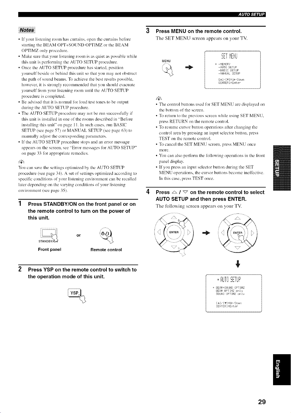
1 Press STANDBY/ON on the front panel or on
the remote control to turn on the power of
this unit.
Front panel Remote control
2 Press YSP on the remote control to switch to
the operation mode of this unit.
3 Press MENU on the remote control.
The SET MENU screen appears on your TV.
++,gi i']_J'iU
+ .MEMORY'
. AIJTO SETUF
.BRSIC SETIJF
. MANUFIL SETUP
[_" [g] :lJ_ "Doun
[ENTER ] : Enter
• The control buttons used for SET MENU are displayed on
the bottom of the screen.
• To return to the previous screen while using SET MENU.
press RETURN on the remote controh
• To resume cursor button operations aller changing the
control area by pressing an input selector button, press
TEST on the remote controh
• To cancel the SET MENU screen, press MENU once
more.
• You can also perform the following operations in the front
panel display.
• If you press an input selector button during the SET
MENU operations, the cursor buttons become ineffective.
In this case, press TEST once.
Press _ / _ on the remote control to select
AUTO SETUP and then press ENTER.
The following screen appears on your TV.
/
]
+
,=,zi_,=, =-_Y+It4
==,HbUJ ;{ U.++
+ BEMM+SOUHD OFf IMZ
EE_qbl OFTIMZ onls
SOUHD OPTIMZ onIJ
[&], [_2 :UF ,[;ouN
[EHI ER] :Enter
29
l_lql",l-'l-'il q +
Press _ / _ to select BEAM OPT+SOUND
OPTIMZ, BEAM OPTIMZ only or SOUND
OPTIMZ only and then press ENTER.
The following screen appears on your TV.
(< "+
1,
riP+r r+r'"+I==T T=_ILl I
FMEFHM_+sLIH
+ iNSIALLING==PaPailei to hJ+li
MEIIJp_TING+ . . . 2,H EL F
REP LEI TING+. NORMRL
Bet P'I]I iK frOrlt 0£ VSP
['1IN 2r'l "6.5£t
[ENTER ] :5t+rt
BEAM OPT+SOUND OPTIMZ
(Beam optimization and YPAO sound
optimization)
Use to optimize tile beam angle, dehty, vohnne and quality
so that the parameters best match your listening
environment.
It is recommended that you should select this optimization
feature in the following cases:
• If you make settings for the first time.
• If the unit has been relocated.
• If your listening room has been restructured.
• If the objects in your listening room (filrniture, etc.)
have been rearranged.
BEAM OPTIMZ only
(Beam optimization only)
Use to optimize the beam angle so that the parameter best
matches your listening environment.
SOUND OPTIMZ only
(YPAO sound optimization only)
Use to optimize the beam delay, volume and quality so
that the parameters best match your listening environment.
It is recommended that you should select this optimization
feature in the t_llowing cases:
• If you have opened or closed the curtains in your
listening room before using this unit.
• If you have manually set the beam angle.
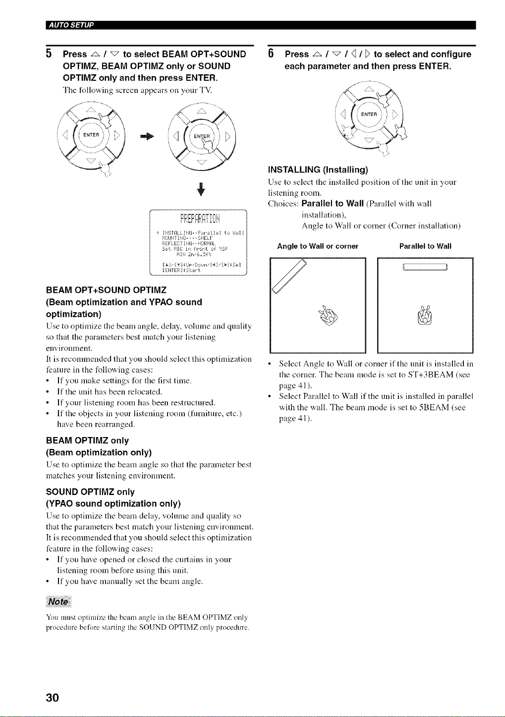
0 Press _ / _ / q / [> to select and configure
each parameter and then press ENTER.
INSTALLING (Installing)
Use to select the installed position of the unit in your
listening room.
Choices: Parallel to Wall (Parallel with wall
installation),
Angle to Wall or corner (Corner installation)
Angle to Wall or corner
/
Parallel to Wall
• Select Angle to Wall or corner if the unit is installed in
the corner. The beam mode is set to ST+3BEAM (see
page 41).
• Select Parallel to W:dl if the unit is installed in parallel
with the wall. The beam mode is set to 5BEAM (see
page 41).
You must optimize the beam angle in the BEAM OPTIMZ only
procedure belbre starting the SOUND OPTIMZ onlyprocedure.
3O
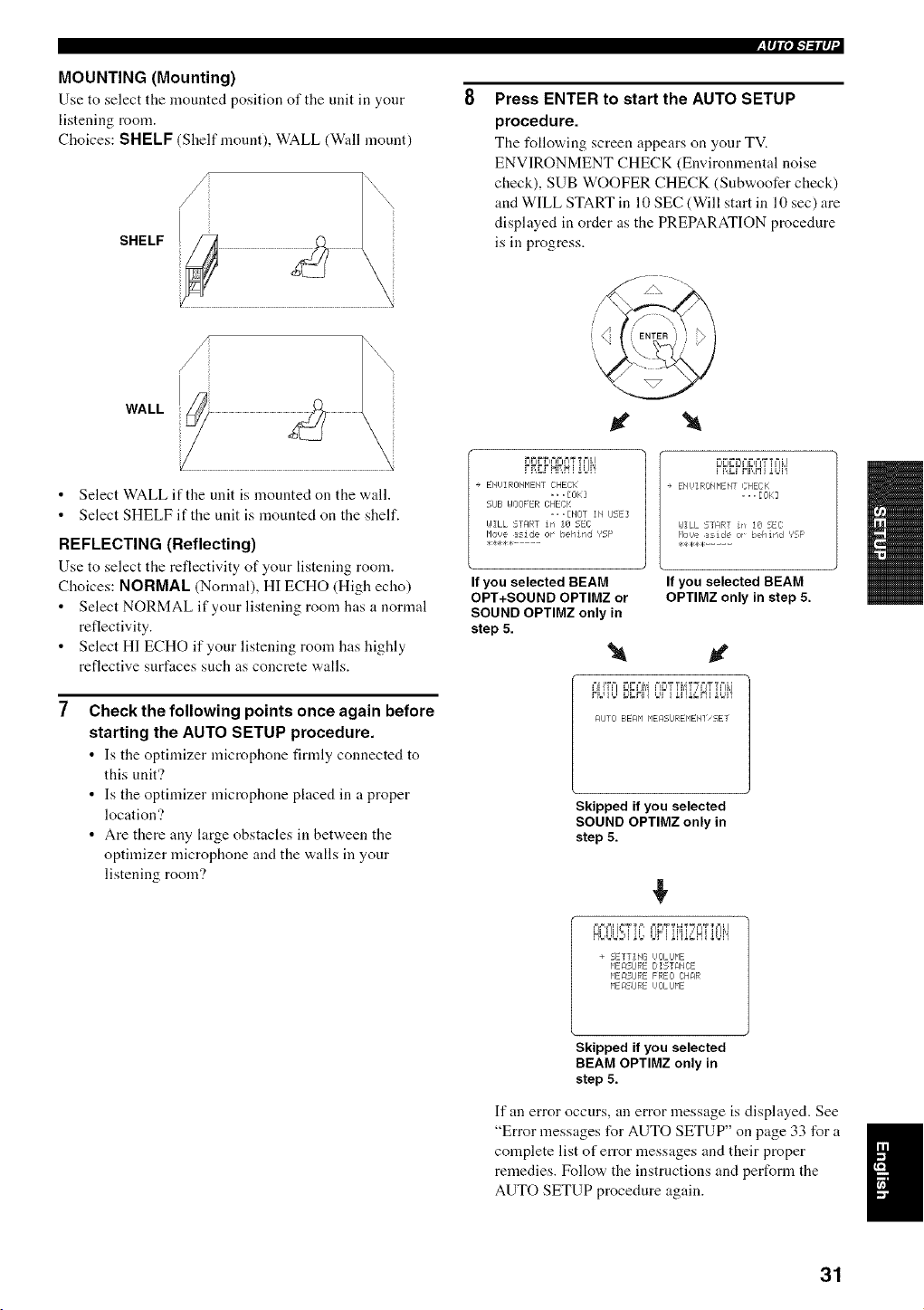
MOUNTING (Mounting)
Use to select tile mounted position of the unit in your
listening room.
Choices: SHELF Shelf mount), WALL (Wull mount)
SHELF
WALL
Select WALL if the unit is mounted on the wall.
Select SHELF if the unit is mounted on the shelf.
REFLECTING (Reflecting)
Use to select the reflectivity of your listening room.
Choices: NORMAL (Normal), HI ECHO (High echo)
Select NORMAL if your listening room has a normal
reflectivity.
Select HI ECHO if your listening room has highly
reflective surfaces such as concrete walls.
Check the following points once again before
starting the AUTO SETUP procedure.
• Is tile optimizer microphone firmly connected to
this unit'?
• Is the optimizer microphone placed in a proper
location'?
• Are there any large obstacles in between the
optimizer microphone and the walls in your
listening room?
,lqP, l-'l-'ilq
Press ENTER to start the AUTO SETUP
procedure.
The following screen appears on your TV.
ENVIRONMENT CHECK (Environmental noise
check), SUB WOOFER CHECK (Subwoofer check)
and WILL START in 10 SEC (Will start in 10 sec) are
displayed in order as the PREPARATION procedure
is in progress.
+ ENUIRONP1ENT CHECK
.., E0 k::]
51JE= UOOFER CHECK
,, ,[NOT IN IJSE]
I,JILL START irl I0 5EC
Houe aside or ¸ behind ','SF'
If you selected BEAM
OPT+SOUND OPTIMZ or
SOUND OPTIMZ only in
step 5.
l e ENUIRONMENT CHEEK
... [0k]
I#ILL 5_ART irf 10 5EC
P'Ii_,_easide or¸¸behind _?SF¸
**4,,H:.....
If you selected BEAM
OPTIMZ only in step 5.
+=jH_== _=I_===M+=I_=4TTMT_T+=j'_'T==Lj
HUU°D_N']tJr+ ii']i,'gHiiM'!
F41JTO BEAM HEMSiJREP1EH] SET
Skipped if you selected
SOUND OPTIMZ only in
step 5.
+
+ SETTING I,IOLIJME
P1ERSLIRE DISTRNCE
HEM:;IJRE FREO CHaR
HEASIJRE UOLIJHE
Skipped if you selected
BEAM OPTIMZ only in
step 5.
If an error occurs, an error message is displayed. See
"Error messages for AUTO SETUP" on page 33 for a I
complete list of error messages and their proper
I
remedies. Follow the instructions and perform the
AUTO SETUP procedure again.
31
l_lql, iF'b,-ilq+
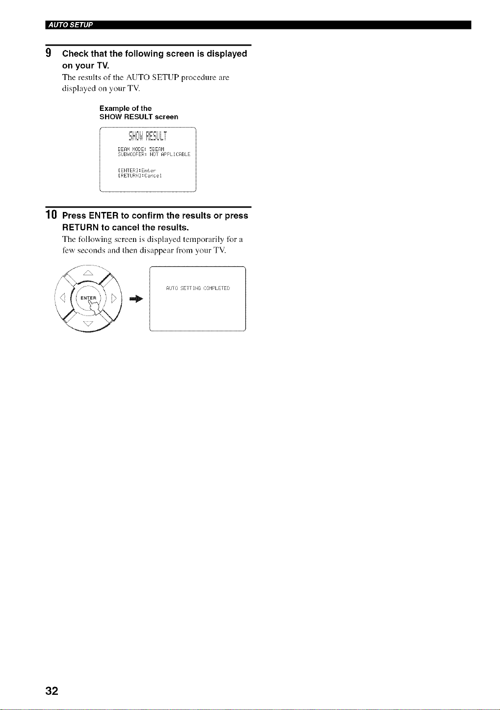
Check that the following screen is displayed
on your TV.
The results of tile AUTO SETUP procedure are
displayed on your TV.
Example of the
SHOW RESULT screen
BEAN MODE: 5BEAbl
21JBI_IOOFER! blOT RFFLII ABLE
[ENTER] : EPft eP
[RETURN : Carioe 1
10 Press ENTER to confirm the results or press
RETURN to cancel the results.
The t_llowing screen is displayed temporarily for a
few seconds and then disappear from your TV.
AVTO SETTING COMPLETED
32
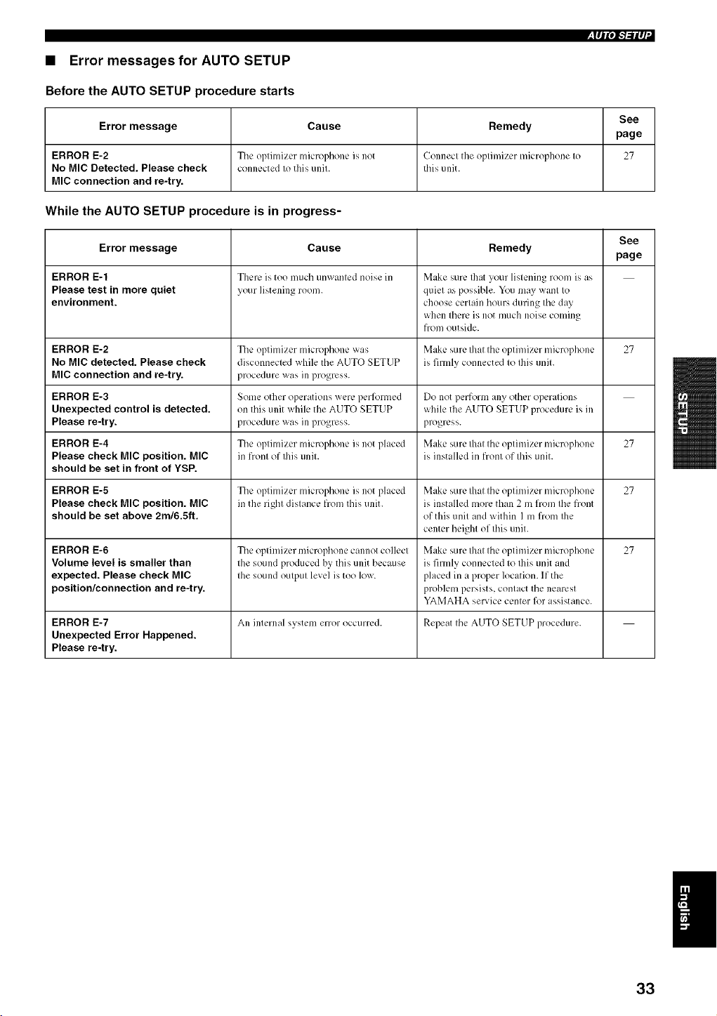
• Error messages for AUTO SETUP
Before the AUTO SETUP procedure starts
See
Error message Cause Remedy
page
ERROR E-2 The optimizer microl)honc is not Connect the optimizer microphone to 27
No MIC Detected. Please check connected to this unit. this unit.
MIC connection and re-try.
While the AUTO SETUP procedure is in progress-
See
Error message Cause Remedy
page
ERROR E-1 There is too much unw_lnted noise in M_Jke sure Ihat your listening room is as
Please test in more quiet your listening room. quiet as possible. You may want to
environment, choose certain hours during the day
when there is not much noise coming
from outside.
ERROR E-2 The optimizer microphone was Make sure that the optimizer microphone 27
No MIC detected. Please check disconnected while the AUTO SETUP is firmly connected to this unit.
MIC connection and re-try, procedure was in progress.
ERROR E-3 Some other operations were perl_rmed Do not perform any other operations
Unexpected control is detected, on this unit while the AUTO SETUP while the AUTO SETUP procedure is in
Please re-try, procedure was in progress, progress.
ERROR E-4 The optimizer microphone is not placed Make sure that the optimizer microphone 27
Please check MIC position. MIC in front of this unit. is installed in front of this unit.
should be set in front of YSP.
ERROR E-5 The optimizer microphone is not phlced M,kc sure that the optimizer microphone 27
Please check MIC position. MIC in the right distance from this unit. is installed more than 2 m from the front
should be set above 2m/6.5ft. of this unit and within 1 m from the
center height of this unit.
ERROR E-6 The optimizer microphone cannot collect Make sure that the optimizer microphone 27
Volume level is smaller than the sound produced by this unit because is firmly connected to this unit and
expected. Please check MIC the sound output level is too low. placed in a proper location. If the
position/connection and re-try, problem persists, contact the nearest
YAMAHA service center lk_rassistance.
ERROR E-7 An internal system error occurred. Repeat the AUTO SETUP procedure.
Unexpected Error Happened.
Please re-try.
I
33
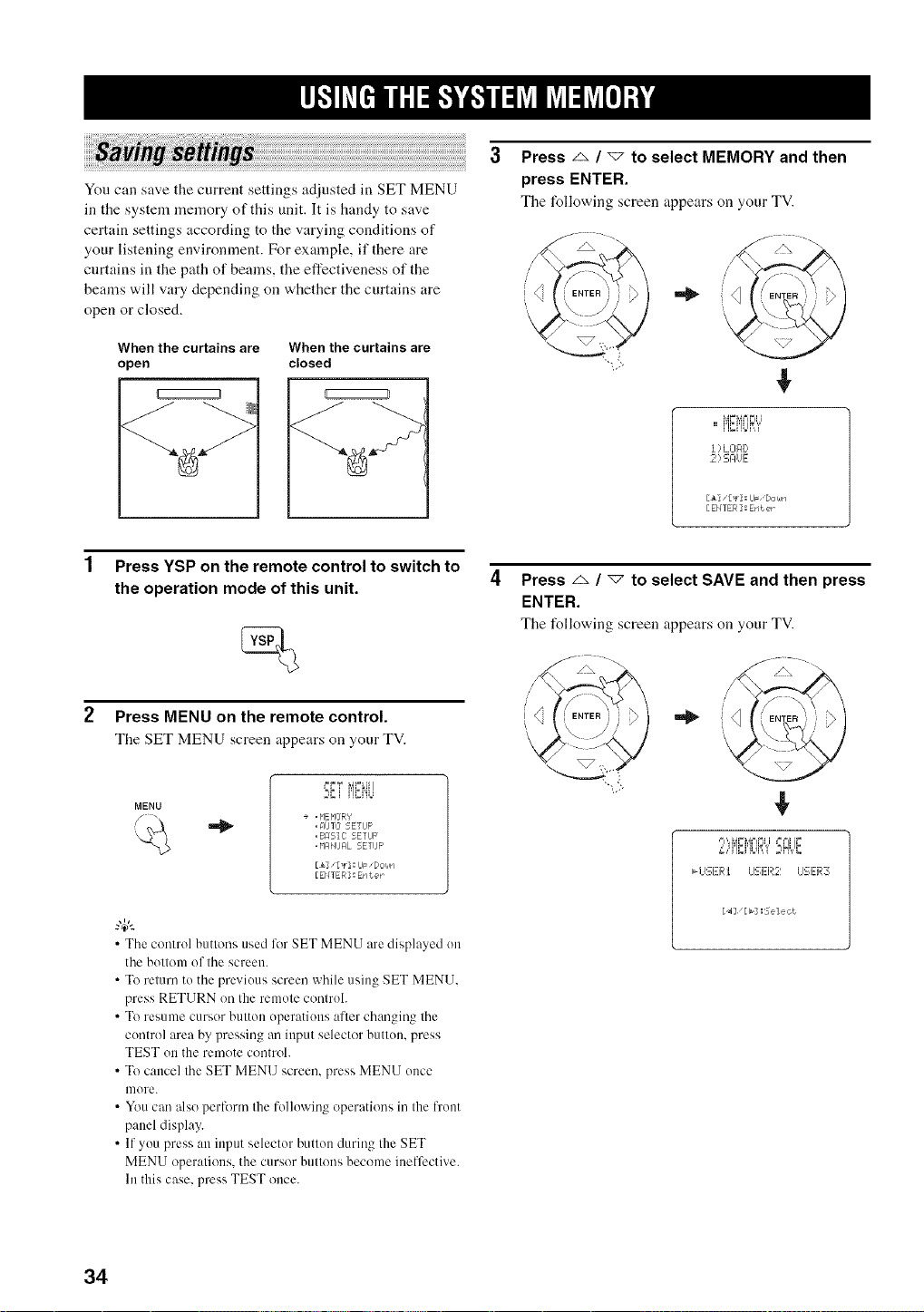
You can save the current settings adjusted in SET MENU
in the system memory of this unit. It is handy to save
certain settings according to the varying conditions of
your listening environment. For example, if there are
curtains in the path of beams, the effectiveness of the
beams will vary depending on whether the curtains are
open or closed.
When the curtains are
open
When the curtains are
closed
Press z_ / _ to select MEMORY and then
press ENTER.
The following screen appears on your TV.
¢
l ) L Ol:ll)
,_I) :_I:IUE
[&]/[_] : IJF,[Jor,ln
[EHTER]: Ent er
Press YSP on the remote control to switch to
the operation mode of this unit.
Press MENU on the remote control.
The SET MENU screen appears on your TV.
MENU
,=_
I=r=T _Ar=Ll!i
w_J ......
+ , MEMOR'/
, MJIO 5ETLIF
,BRSll SETUP
, _'l_l_lJAL 5ETIJF'
[&]/[_] : IJF "Dot,in
[EHTER] : Enter
• The control buttons used liar SET MENU are displayed on
the bottom of the screen.
• To return to the previous screen while using SET MENU.
press RETURN on the remote controh
• To resume cursor button operations after changing the
control area by pressing an input selector button, press
TEST on the rmnote control.
• To cancel the SET MENU screen, press MENU once
more.
• You can also perform the lollowing operations in the l?'ont
panel display.
• If you press an input selector button during the SET
MENU operations, the cursor buttons become ineffective.
In this case, press TEST once.
Press z_ / "7 to select SAVE and then press
ENTER.
The following screen appears on your TV.
/
i'<
¢
34
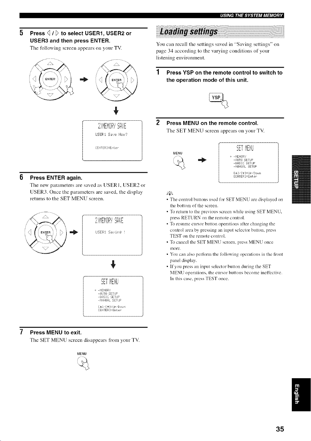
r_ l ,V[efl l ; I ,:l,.*J"_,.*Jfl _&_l J_l _&_[e] ; i
Press q / D to select USER1, USER2 or
USER3 and then press ENTER.
The following screen appears on your TV.
J
,!,
,= ',,',_.'=N== F ====J!I.'=
,",,i'}_Ht!_iliI ;,H,,,,r
LISER1 S_,,_e 1'4c,<,_7'
[EHI ER] : Enter
Press ENTER again.
Tire ne'a, parameters are saved as USERI, USER2 or
USER3. Once the parameters are saved, the display
returns to the SET MENU screen.
"ipiqr i ,=,'i_ir
J:Ef, :.--mvirr_ !
}; i i']_i'!b
÷ . NENOR'f
,gUT] SETIJP
.BRSIC SETUP
. NAMJFIL SETUF ¸
[i], [g] : IJF"DOralrl
[EHI ER] : Enter
You can recall the settings saved in "Saving settings" on
page 34 according to the varying conditions of your
listening environment.
1 Press YSP on the remote control to switch to
the operation mode of this unit.
2 Press MENU on the remote control.
The SET MENU screen appears on your TV.
MENU
i=.'=T NFLII I
E¢.i i']gi%I
÷ . NENOR/
. AIJTO SETUP
.BRSIC SETIJF'
. _'IAMURL SETUP
[A]" [g] :lJ_ ,[/Olaln
[EHTER ] : Erlt er
•The control buttons used for SET MENU are displayed on
the bottom of the screen.
• To return to the previous screen while using SET MENU.
press RETURN on the remote control.
• To resume cursor button operations alter changing the
control area by pressing an input selector button, press
TEST on the remote control.
• To cancel the SET MENU screen, press MENU once
u/ore.
• Youcan also perform the followingoperations in the front
panel display.
• If you press an input selectur button during the SET
MENU operations, the cursor buttons become ineffi:ctive.
In this case, press TEST once.
Press MENU to exit.
The SET MENU screen disappears from your TV.
MENU
I
35
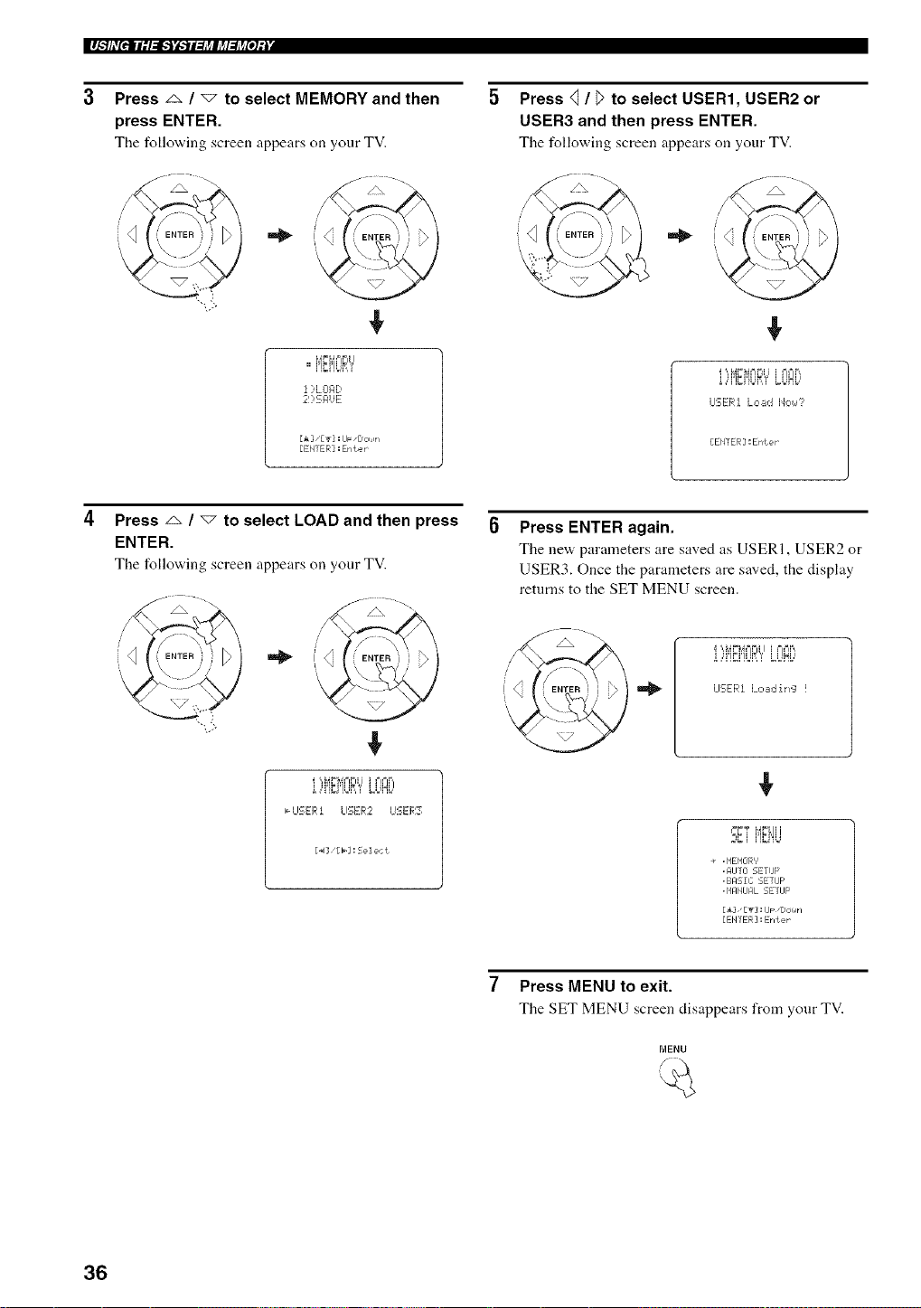
IlJ.']hV[elll:l:J.'i'i._JI3J_lj_l:lj_[o];| '
Press _ / "7 to select MEMORY and then
press ENTER.
The following screen appears on your TV.
!
,,MEMORY
i )L01:1D
21)EI:IUE
[A] ,[_r]:IJF ,Doiirl
[EN] ER] : Erlter
Press <] / _>to select USER1, USER2 or
USER3 and then press ENTER.
The following screen appears on your TV.
LIEER] L,:,._d lJo_,_?
[ENTER ] :ENter
Press z_ / "_ to select LOAD and then press
ENTER.
The following screen appears on your TV.
i ,,q'}_i'lUP,'i' LUlL,I
,,,-I_I'SER1 LISE[4::2 U'_:ER3
[4][b]:Select
Press ENTER again.
The nev,, parameters are saved as USERI, USER2 or
USER3. Once the parameters are saved, the display
returns to the SET MENU screen.
i ',A4_=_,4==FI i i===l.'=,,
o,,,£,,o!_,_ _o!Ho,
LI'_ERI Loadih'_:l !
'°_',_,i'iFi'4ii
w_J ......
÷ , HEHEIR'_'
, AIJTO SETUP
,BASIC SETIJF
. HAMJFIL 5ETIJP
[i], [T]: IJF "DOr_lri
[EHTER] : Enter
Press MENU to exit.
The SET MENU screen disappears from your TV.
MENU
36
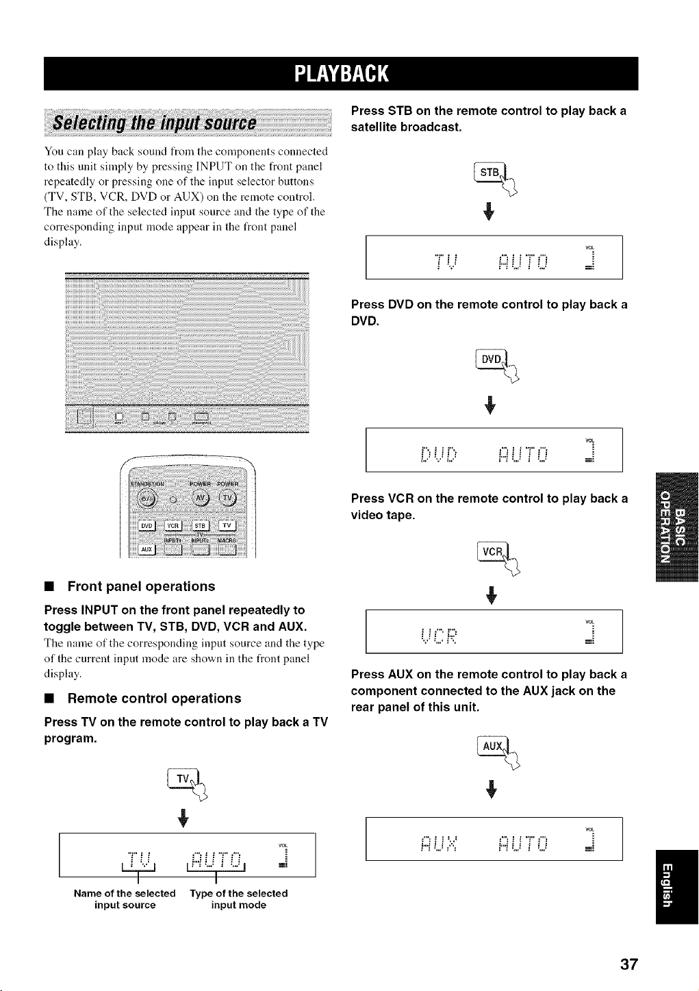
You can play back sound from the components connected
to this unit simply by pressing INPUT on the front panel
repeatedly or pressing one of the input selector buttons
(TV, STB, VCR, DVD or AUX) on the remote control.
The name of the selected input source and the type of the
corresponding input mode appear in the front panel
display.
Press STB on the remote control to play back a
satellite broadcast.
€
VOL
7 U70 ==
Press DVD on the remote control to play back a
DVD.
€
VOL
i", i i F', !"__ i T _'"_
L,: R: _ " _'"! L2 3 =.,._ m:
• Front panel operations
Press INPUT on the front panel repeatedly to
toggle between TV, STB, DVD, VCR and AUX.
Tile name of the corresponding input source and the type
of the current inpnt mode are shown in the front panel
display.
• Remote control operations
Press TV on the remote control to play back a TV
program.
€
rOE
"F _ ! =%! ! "F _"'=
Name of the selected Type of the selected
input source input mode
Press VCR on the remote control to play back a
video tape.
€
VOL
i ! _ i;:=
Press AUX on the remote control to play back a
component connected to the AUX jack on the
rear panel of this unit.
€
VOL
i"_L) ='"_ P'iLJ _ LJ -==
37
Once an input source is selected (see page 37), you can
play back the selected input source.
This section uses a DVD player as an example of the playback
source.
"4(--
Fur details on the TV and the DVD plwer you are using, refer to
the owner's manual supplied with the TV and the DVD player.
1 Turn on the power of your DVD player using
the remote control supplied with the DVD
player.
2 Switch to the video input on your TV using
the remote control supplied with the TV so
that the DVD menu screen is displayed.
3 If necessary, turn down the volume of your
TV until you cannot hear any sound.
4 Press DVD on the remote control to select
DVD as the input source.
5 Play back the DVD on your DVD player using
the supplied remote control.
Audio signals froln your DVD player are output from
the speakers of this unit.
• If the uutput volume is tou luw. increase the volume on this unit
to around 25 dB.
• If you have set the apprupriate remote control codes lor your
TV and DVD plwer, yuu can use the remote control supplied
with this unit to operate these components. For details on how
tu set remote cuntrol codes, see page 82.
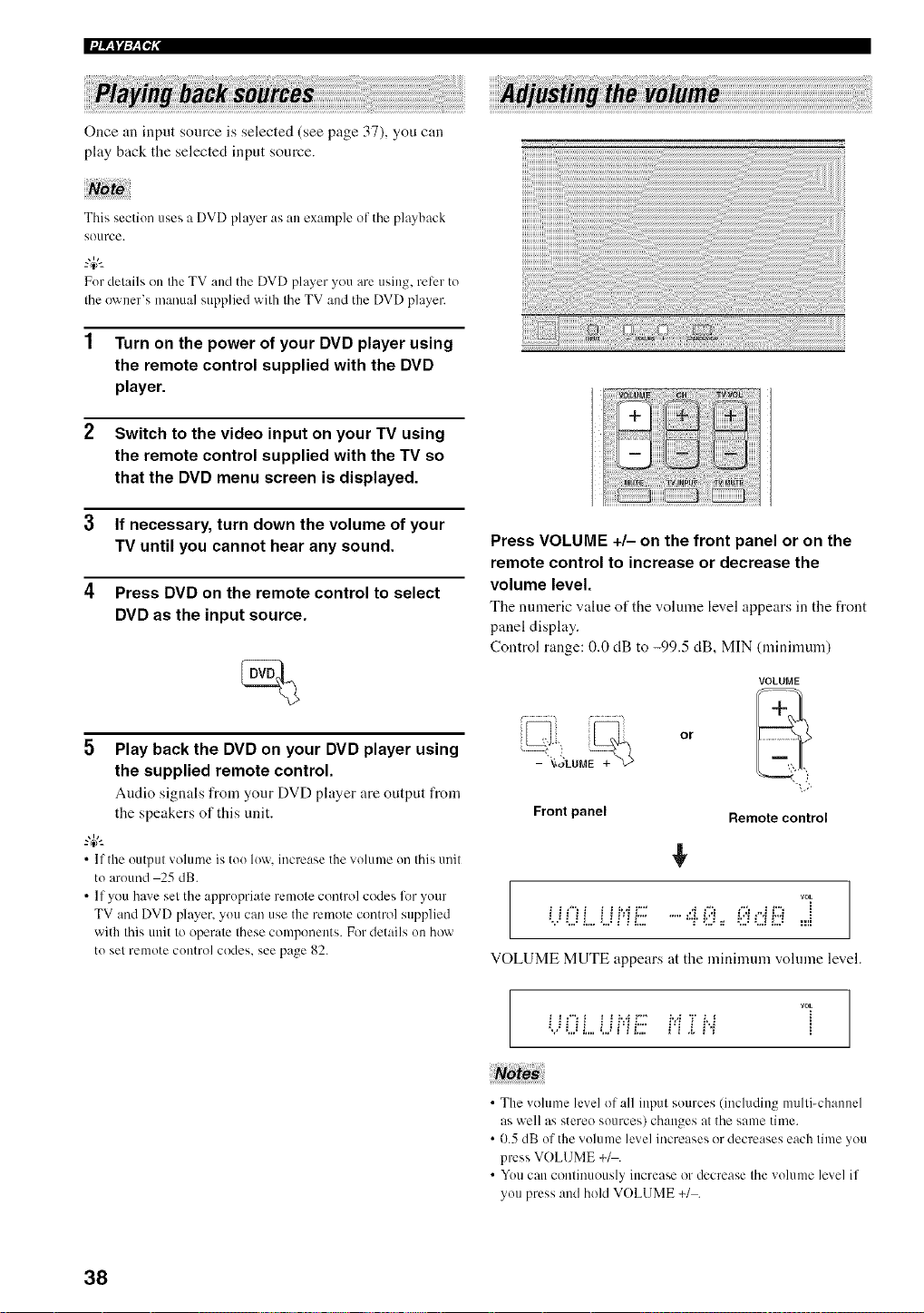
Press VOLUME +/- on the front panel or on the
remote control to increase or decrease the
volume level.
The numeric value of the volume level appears in the front
panel display.
Control range: 0.0 dB to -99.5 dB, MIN (minimum)
Front panel
or
VOLUME
Remote control
rOE
_,..:!..,!L.. i.,.!_'Ji2_ "r _;.._=_ _:.2L.I!.,,_ .=.==_
VOLUME MUTE appears at the minimum vohnne level.
U0 L LIHE Hiiii..i
• The volunm level of all input sources (including multi-channel
as well as stereo sources) changes at the same time.
• 0.5 dB uf the volume level increases or decreases each time you
press VOLUME +_.
• Yuu can continuously increase or decrease the volume level if
you press and hold VOLUME +1 .
38
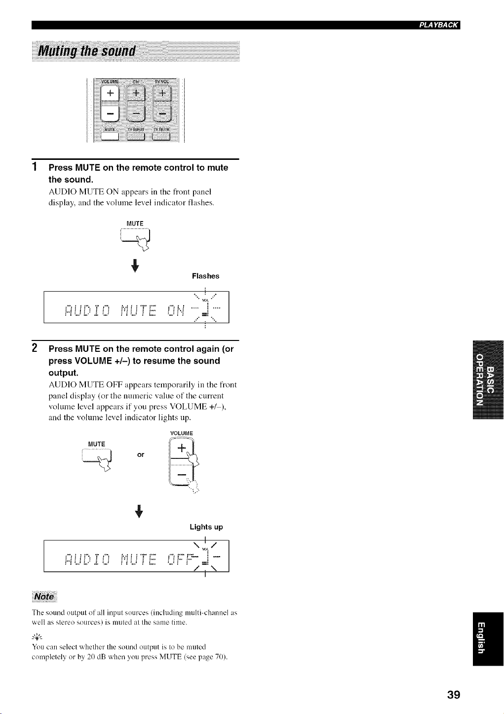
Press MUTE on the remote control to mute
the sound.
AUD]O MUTE ON appears in the front p:mel
display, and the vohnne level indicator flashes.
MUTE
¢
Flashes
**÷ @ ÷÷
• rOE •
i
÷÷'* , "%
2
Press MUTE on the remote control again (or
press VOLUME +/-) to resume the sound
output.
AUDIO MUTE OFF appears temporarily in the front
panel display (or the numeric value of the current
volume level appears if you press VOLUME +/ ),
and the volume level indicator lights up.
VOLUME
MUTE
Or
¢
Lights up
\ v!L/
i"i :...._i./ .i. L) i'i L._ i i.... :...._i" i"" =i
/ \
I
The sound output of all input sources (including multi-channel as
well as stereo sources) is muted at the same time.
"4¢--
Youcan select whether the sound output is tobe muted
completely or by 20 dB when youpress MUTE (see page 70).
39
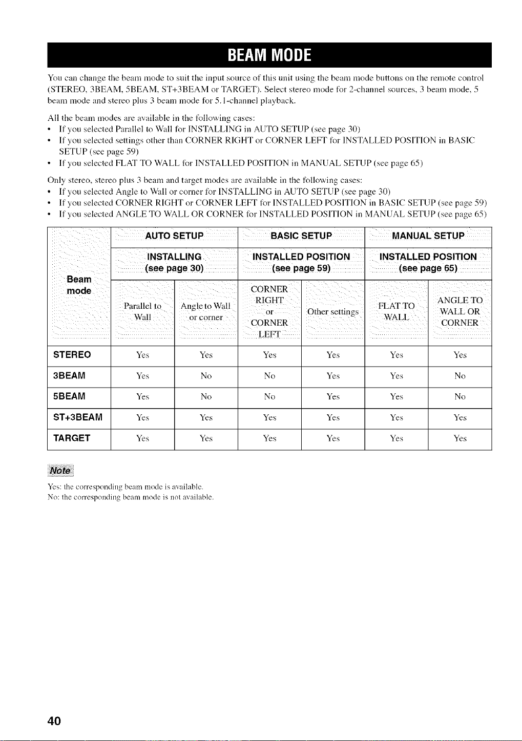
You can change the beam mode to suit the input source of this unit using the beam mode buttons on the remote control
(STEREO, 3BEAM, 5BEAM, ST+3BEAM or TARGET). Select stereo mode I\)r 2-channel sources, 3 beam mode, 5
beam mode and stereo plus 3 beam mode for 5. l-channel playback.
All the beam modes are available in the t_llowing cases:
• If you selected Parallel to Wall for INSTALLING in AUTO SETUP (see page 30)
• If you selected settings other than CORNER RIGHT or CORNER LEFT for INSTALLED POSITION in BASIC
SETUP (see page 59)
• If you selected FLAT TO WALL for INSTALLED POSITION in MANUAL SETUP (see page 65)
Only stereo, stereo plus 3 beam and target modes are available in the following cases:
• If you selected Angle to Wall or corner for INSTALLING in AUTO SETUP (see page 30)
• If you selected CORNER RIGHT or CORNER LEFT t_r INSTALLED POSITION in BASIC SETUP (see page 59)
• If you selected ANGLE TO WALL OR CORNER for INSTALLED POSITION in MANUAL SETUP (see page 65)
INSTALLED POSITION
i i i LEFT : : :
STEREO Yes Yes Yes Yes Yes Yes
3BEAM Yes No No Yes Yes No
5BEAM Yes No No Yes Yes No
ST+3BEAM Yes Yes Yes Yes Yes Yes
TARGET Yes Yes Yes Yes Yes Yes
Yes: the corresporJding beam mode is available.
No: the corresponding beam mode is nol available.
4O
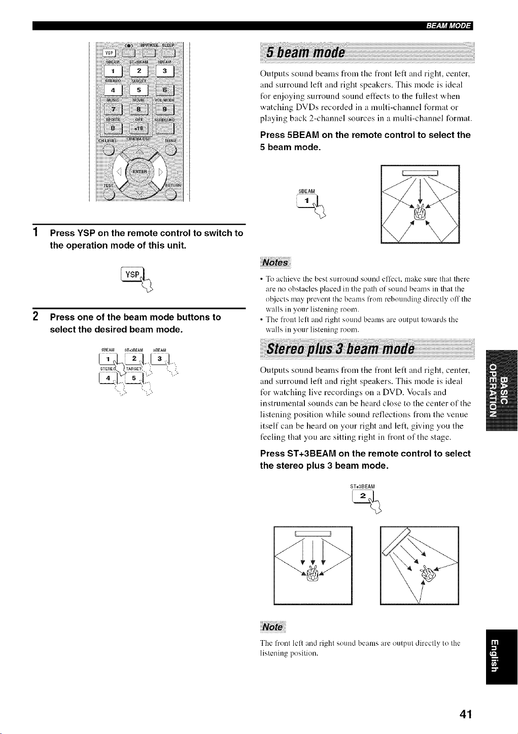
1 Press YSP on the remote control to switch to
the operation mode of this unit.
Press one of the beam mode buttons to
select the desired beam mode.
5BEAM ST*3BEA_ a_EAM
STERE TARGEt', _ _
Outputs sound beams from the front left and right, center,
and surround left and right speakers. This mode is ideal
for enjoying surround sound effects to the fullest when
watching DVDs recorded in a multi-channel format or
playing back 2-channel sources in a multi-channel format.
Press 5BEAM on the remote control to select the
5 beam mode.
5BEAM
CZ;;;;;;;;;;Z3
• To achieve the best surround sound el'liect, make sure that there
are no obstacles placed in the path of suund beams in that the
ol_iects may prevent the beams from rebounding directly off the
walls in your listeuing ruom.
• The front lell and right sound beams are output towards the
walls in your listening roum.
Outputs sound beams from the front left and right, center,
and surround left and right speakers. This mode is ideal
tbr watching live recordings on a DVD. Vocals and
instrumental sounds can be heard close to the center of the
listening position while sound reflections from the venue
itself can be heard on your right and left, giving you the
feeling that you are sitting right in front of the stage.
Press ST+3BEAM on the remote control to select
the stereo plus 3 beam mode.
ST+3BEAM
The Front left and righl sound beams are output directly to the
listening position.
41
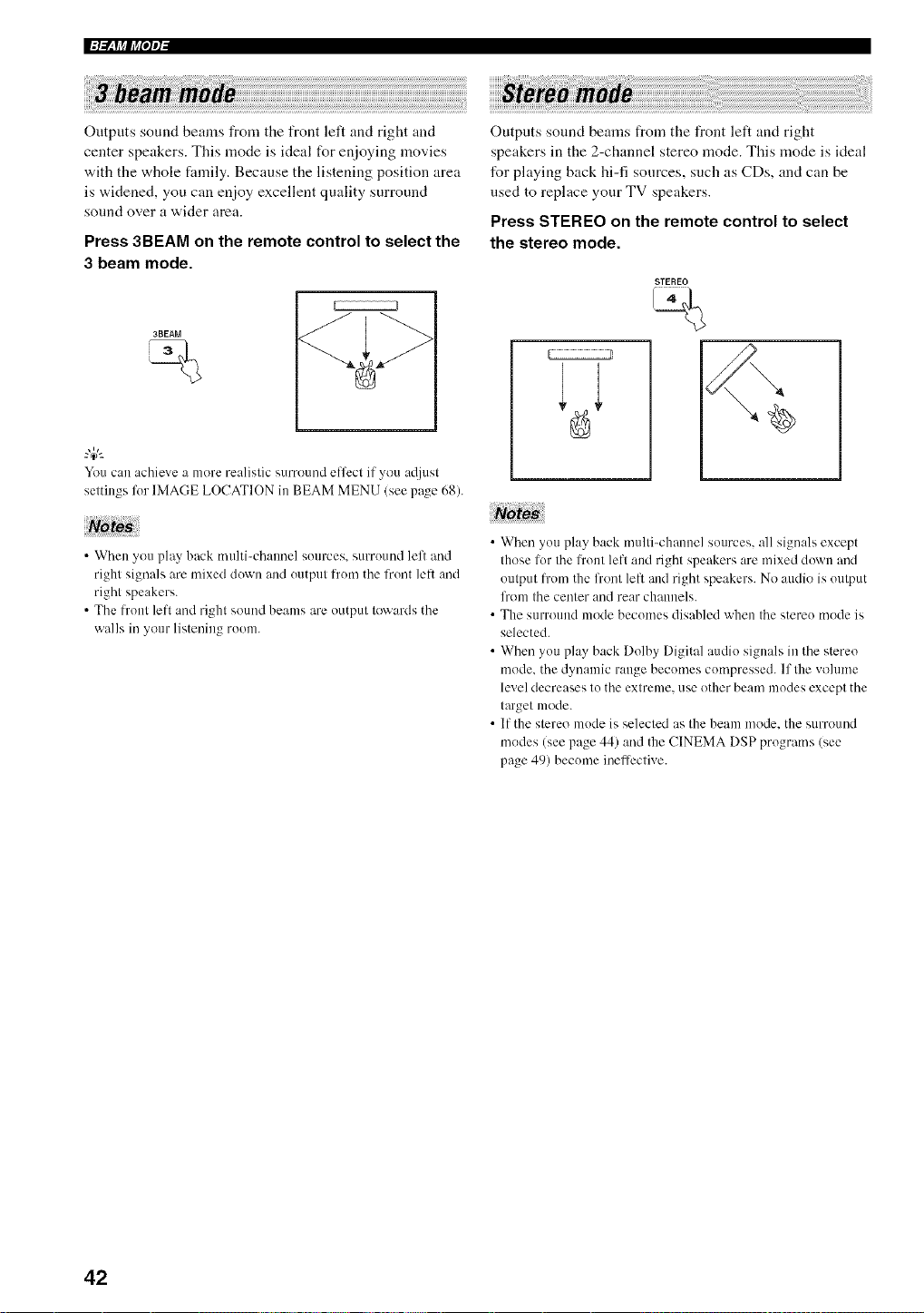
Outputs sound beams from the front left and right and
center speakers. This mode is ideal for enjoying movies
with the whole family. Because the listening position area
is widened, you can enjoy excellent quality surround
sound over a wider area.
Press 3BEAM on the remote control to select the
3 beam mode.
3BEAM
You can achieve a more realislic surround effect if you a@lsl
settings lot IMAGE LOCATION in BEAM MENU (see page 68).
Note
• When you play back nmlti-chaunel sources, surround left and
right signals are mixed down and output from the front lelt and
right speakers.
• The l?'out left and right sound beams are output towards the
walls in your listening room.
Outputs sound beams from the front left and right
speakers in the 2-channel stereo mode. This mode is ideal
for playing back hi-fi sources, such as CDs, and can be
used to replace your TV speakers.
Press STEREO on the remote control to select
the stereo mode.
STEREO
• When you play back multi-channel sources, all signals except
those lor the l_'ont left and right speakers are mixed down and
output l_x)mthe front left and right speakers. No audio is output
lhom the center and rear channels.
• The surround mode becomes disabled when the stereo mode is
selected.
• When you play back Dolby Digital audio signals in the stereo
mode. the dynamic range becomes compressed. If the vollHne
level decreases to the extreme, use other beam modes except the
target mode.
• If the stereo mode is selected as the beam mode. the surround
modes (see page 44) and the CINEMA DSP programs (see
page 49) becmne inefli:ctive.
42
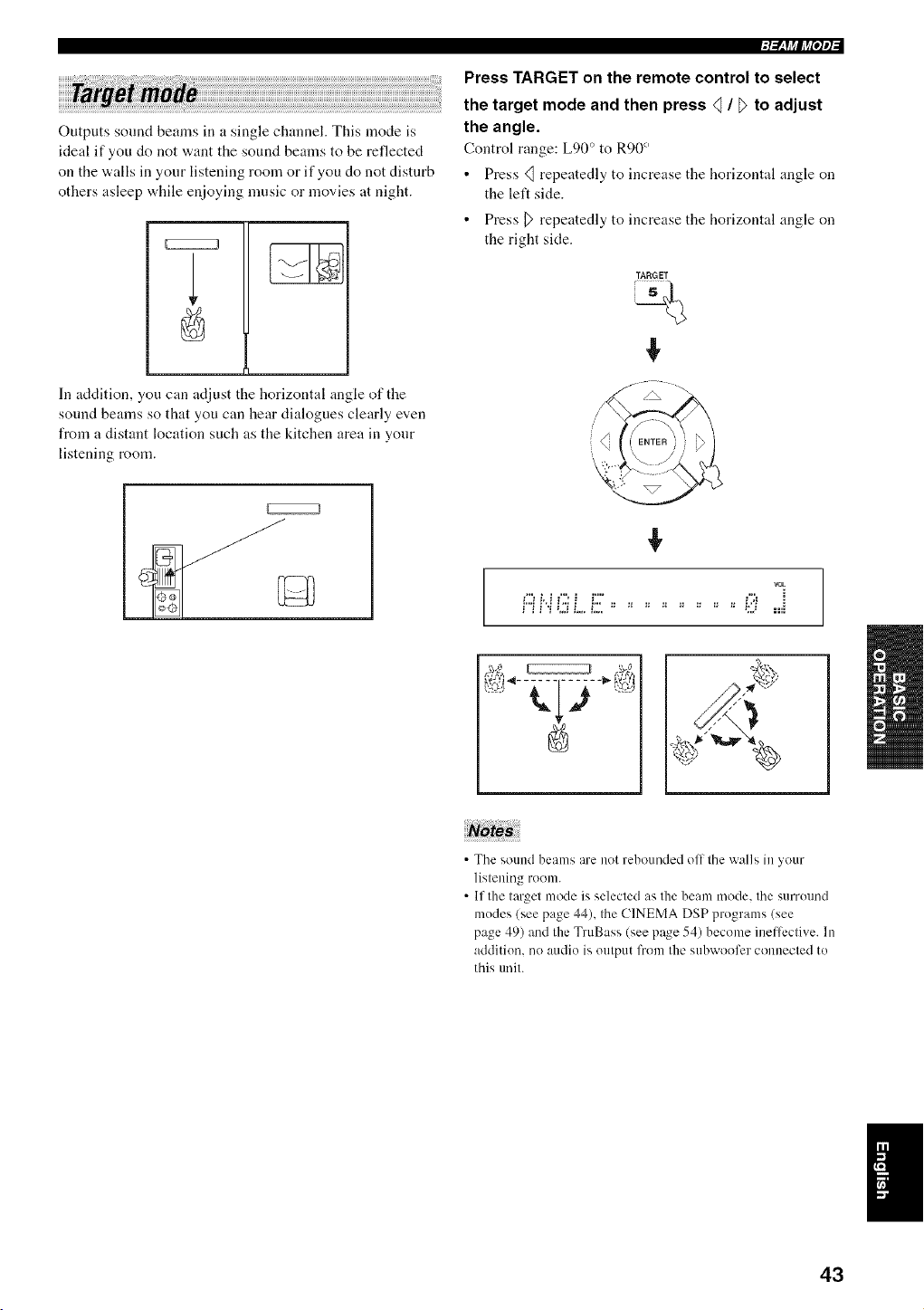
Outputs sound beams in a single channel. This mode is
ideal if you do not want the sound beams to be reflected
on the walls in your listening room or if you do not disturb
others asleep while enjoying nmsic or movies at night.
In addition, you can adjust the horizontal angle of the
sound beams so that you can hear dialogues clearly even
from a distant location such as the kitchen area in your
listening room.
Press TARGET on the remote control to select
the target mode and then press _ / _ to adjust
the angle.
Control range: Lg0 ° to R90 °
• Press <_ repeatedly to increase the horizontal angle on
the left side.
• Press D repeatedly to increase the horizontal angle on
the right side.
TARGET
%
vok
i::ii".t L ff ................ i;i: ....=i
• The sound beams are not rebounded off the walls in your
listening room.
• If the target mode is selected as the beam mode. the surround
modes (see page 44), the CINEMA DSP programs (see
page 49) and the TruBass (see page 54) become ineffi:ctive. In
addition, no audio is output from the subwoofcr connected to
this tmit.
43
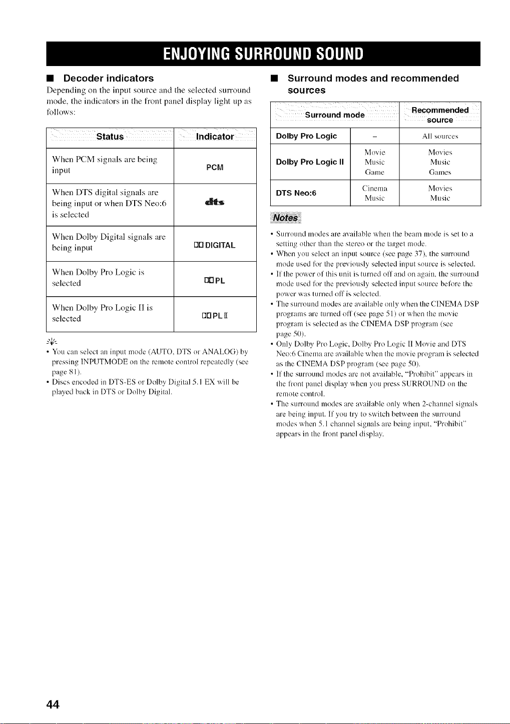
• Decoder indicators
Depending on tire input source :rod the selected surround
mode, the indicators in the front panel display light up as
follows:
i
Status . Indicator
When PCM signals are being
input PCM
When DTS digital signals are
being input or when DTS Neo:6
is selected
When Dolby Digital signals are
being input OO DIGITAL
When Dolby Pro Logic is
selected O0 Pk
When Dolby Pro Logic I1 is
selected O0 PL 1I
• You can select an input mode (AUTO, DTS or ANALOG) by
pressing INPUTMODE on the remote control repeatedly (see
page 81 ).
• Discs encoded in DTS-ES or Dolby Digital 5. I EX will be
played back in DTS or Dolby Digital.
• Surround modes and recommended
sources
Surround mode
. source
Dolby Pro Logic All sources
Movie Movies
Dolby Pro Logic II Music Music
Game Games
Cinema Movies
DTS Neo:6
Music Music
• Surround modes are available when the beam mode is set to a
setting other than the stereo or the target mode.
• When you select an input source (see page 37), the surround
mode used for the previously selected input source is selected.
• If the power of this unit is turned ofl and on again, the surround
mode used lor the previously selected input source before the
power was turned off is selected.
• The surround modes are available only when the CINEMA DSP
programs are turned of 1(see page 51) or when the movie
program is selected as the CINEMA DSP program (see
page 50).
• Only Dolby Pro Logic, Dolby Pro Logic II Movie and DTS
Neo:6 Cinema are available when the movie program is selected
as the CINEMA DSP program (see page 50).
• If the surround modes are m)t available, +'Prohibit" appears in
the li+ontpanel display when you press SURROUND on the
remote control.
• The surround modes are available only when 2-channel signals
are being input. If you try to switch between the surround
modes when 5.1 channel signals arc being input, "Prohibit"
appears in the fl+ontpanel display.
44
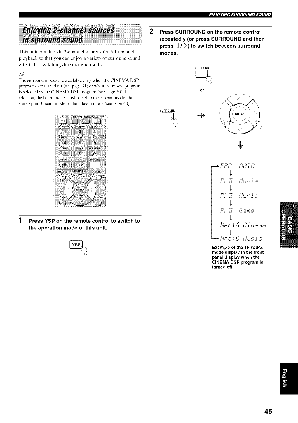
This unit can decode 2-channel sources for 5.1 channel
playback so that you can enjoy a variety of surround sound
effects by switching the surround mode.
The surruund modes are available only when the CINEMA DSP
prugrams are turned uff (see page 51 ) or when the movie program
is selected as the CINEMA DSP program (see page 50). In
addition, the beam mude must be set to the 5 beam mode, the
stere() plus 3 beam mode or the 3 beam mude (see page 40).
_hVlrtIe,ltyhV[eig']#l_l_{el#hVel_',Iel#l_VJ
Press SURROUND on the remote control
repeatedly (or press SURROUND and then
press _ / _) to switch between surround
modes.
SURROUND
or
SURROUND i
\
Press YSP on the remote control to switch to
the operation mode of this unit.
t,,J t t t tW ," t _ "_ ,-,
,L
t,,_t tt tWt _',, _ ,"
,L
L;?i TT i:;?:'..!'_'_,:::,
$
t,d,-, ,-', _ t; t " _ t," ,-, t',,, -,
Example of the surround
mode display in the front
panel display when the
CINEMA DSP program is
turned off
45
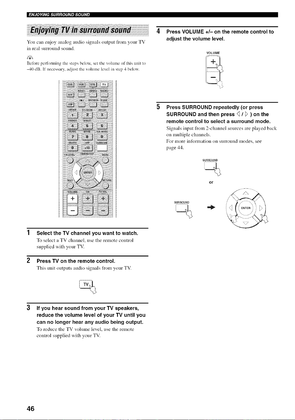
I_hVR[eJyhV[e_#Jglg[e1#J_VeJ_'_e1#hvi,
You call enjoy analog audio signals output from your TV
in real surround sound.
Before performing the steps below, sel the volume ol Ihis unit to
40 dB. If necessary,adjust the volume level in step 4 below.
4 Press VOLUME +/- on the remote control to
adjust the volume level.
VOLUME
Select the TV channel you want to watch.
To select a TV channel, use the remote control
supplied w,ith your TV.
Press TV on the remote control.
This unit outputs audio signals from your TV.
If you hear sound from your TV speakers,
reduce the volume level of your TV until you
can no longer hear any audio being output.
To reduce the TV volume level, use the remote
control supplied with your TV.
Press SURROUND repeatedly (or press
SURROUND and then press <1/ _7) on the
remote control to select a surround mode.
Signals input from 2-channel sources are played back
on nmltiple channels.
For more information on surround modes, see
page 44.
SURROUND
SURROUND
or
46
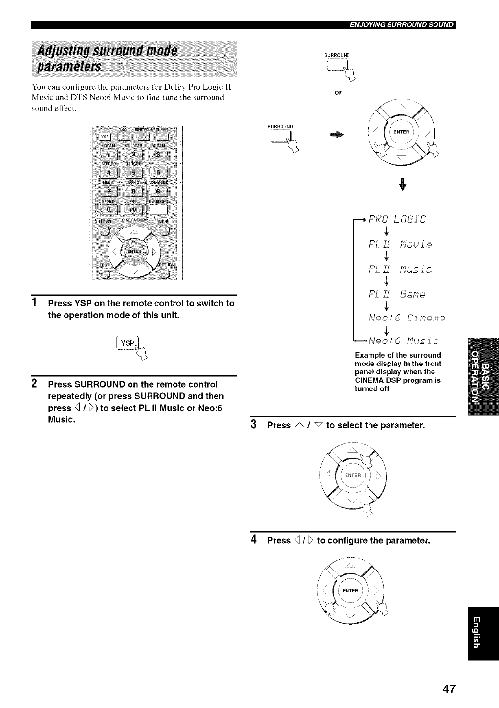
=l_Vlrt[eJ¥1_v[eff,."Y#l:l:{e]#l_Vel_'fe]#l_VJ
You can configure the parameters for Dolby Pro Logic lI
Music and DTS Neo:6 Music to fine-tune the surround
sound effect.
SURROUND
SURROUND
or
Press YSP on the remote control to switch to
the operation mode of this unit.
Press SURROUND on the remote control
repeatedly (or press SURROUND and then
press _ / _>)to select PL II Music or Neo:6
Music.
:,-, :,-. ,,-, : ,,-, ,,-, ,:, ,.
t,,.: t it tW ,=" : _ "_ ,-.,
,L
t.,.:t it tW: _',. _ ,"
: :=. a,,_. ,=: ,.a : : ,,
$
::,.,,=,- ,=, ".,'a,::'=::'=a
: : .. ,- :--: •
i _:LTL,: = LJ IIL.I,L_,d,_,,
Example of the surround
mode display in the front
panel display when the
CINEMA DSP program is
turned off
Press _ / _ to select the parameter.
4 Press _ / _>to configure the parameter.
47
I_hV_[eJyhV[e_#JM_[eJ#hVeJ_'_eJ#J_Vi,
When Dolby Pro Logic II Music is
selected
PANORAMA
Gives front left :rod right channel sound a wraparound
effect, distributed throughout the entire surround
sound fiekt to give you an expansive feeling.
Choices: ON/OFF
Default setting: OFF
DIMENSION
Adjusts the difference in volume between front and
surround channels to the volume balance you desire.
Control range: -3 (toward the surround direction) to
+3 (toward the front direction)
Default setting: STD
CT WIDTH
Distributes the center channel sound to the left and
right. If set to 0, center channel sounds output only
from the center speaker.
Control range: 0 to 7
Default setting: 3
• When DTS Neo:6 Music is selected
C. IMAGE
Adjusts the center image from three speakers (front
and center) to varying degrees.
Control range: 0.0 (wider) to 1.0 (toward the center)
Dethult setting: 0.3
48
This unit is equipped with a variety of precise digital decoders that allow you to enjoy multi-channel playback from
stereo or nmlti-channel sources. This unit is also equipped with a YAMAHA CINEMA DSP (digital sound field
processing) chip containing several sound field programs which you can use to enhance your playback experience. Most
of the sound field programs are precise digital recreations of actual acoustic environments t_unct in famous concert halls,
music venues and movie theaters.
The YAMAHA CINEMA DSP modes are compatible with all Dolby Digital. DTS and Dolby Surround sources.
Choose a sound field progr:un based on your listening preference and do not purely rely on the name of the sound field program itself.
A significant factor that creates the rich, full tones of a live instrument are the multiple reflections from the walls of the
room. In addition to nmking the sound live, these reflections enable the listener to tell where the player is situated as well
as the size and shape of the room in which the listening is sitting.
• Elements of a sound field
In any environment, there are two distinct types of sound reflections that combine with the direct sound coming straight
to our ears from the player's instrument to make up the sound field.
Early reflections
Reflected sounds reach onr ears extremely rapidly (50 ms to 100 ms after the direct sound) after reflecting from one
surface only (l_om the ceiling or a wall, for example). Early reflections help add clarity to the direct sound.
Reverberations
These are caused by reflections from more than one surface (i.e. wall, ceiling, tile back of the room, etc.) so numerous
that they merge together to form a continuous sonic afterglow. They are non-directional and lessen the clarity of the direct
sonnd.
Direct sound, early reflections and subsequent reverberation taken together help us to determine the subjective size and
shape of the room, and it is this information that the digital sound field processor reproduces in order to create sound
fields.
If yon could create the appropriate early reflections and subsequent reverberations in your listening room, you would be
able to create your own listening environment. The acoustics in your room could be changed to those of a concert hall, a
dance floor or a listening room of virtually any size at all. This ability to create sound fields at will is exactly what
YAMAHA has clone with the CINEMA DSP technology.
49
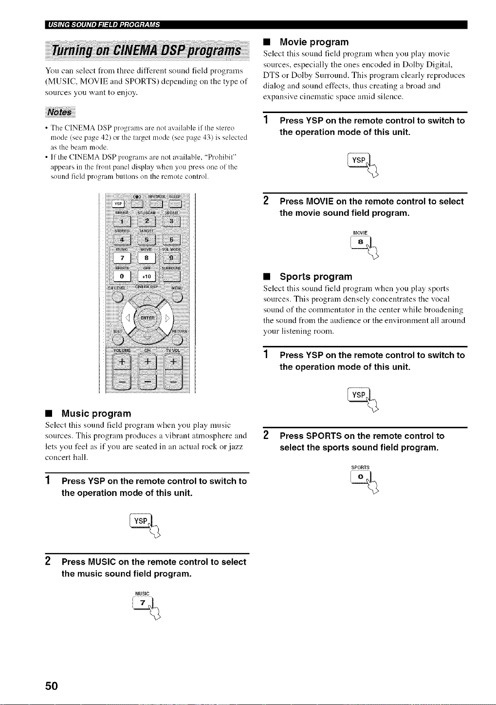
You can select from three different sound field programs
(MUSIC, MOVIE and SPORTS) depending on the type of
sources you want to enjoy.
• The CINEMA DSP programs are not available if the stereo
mode (see page 42) or the target mode (see page 43) is selected
as the beam mode.
• If the CINEMA DSP programs are not m ailable, "Prohibit"
appears in the h'ont panel display when yoMpress one of the
sound field program huttons oi1 the rmnote controh
• Music program
Select this sound field program when you play music
sources. This program produces a vibrant atmosphere and
lets you feel as if you are seated in an actual rock or jazz
concert hall.
1 Press YSP on the remote control to switch to
the operation mode of this unit.
• Movie program
Select this sound fiekt program "a,hen you phty movie
sources, especially the ones encoded in Dolby Digital,
DTS or Dolby Surround. This program clearly reproduces
dialog and sound effects, thus creating a broad and
expansive cinematic space an]id silence.
1 Press YSP on the remote control to switch to
the operation mode of this unit.
2 Press MOVIE on the remote control to select
the movie sound field program.
MOVIE
• Sports program
Select this sound field program "a,hen you play sports
sources. This program densely concentrates the vocal
sound of the commentator in the center while broadening
the sound from the audience or the environment :111around
your listening room.
1 Press YSP on the remote control to switch to
the operation mode of this unit.
Press SPORTS on the remote control to
select the sports sound field program.
SPORTS
,<
Press MUSIC on the remote control to select
the music sound field program.
MUSIC
%
50
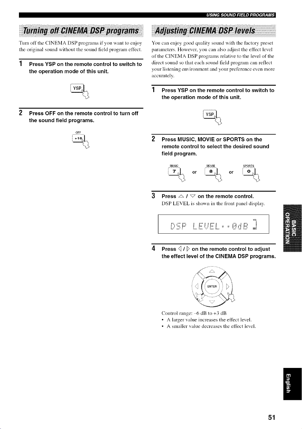
et.*_hV[e_.*fe]#J_VeJ_l_llle1_:[ele_:y_,fj_l,
Turn off the CINEMA DSP programs if you want to er_joy
the original sound without the sound field program effect.
1 Press YSP on the remote control to switch to
the operation mode of this unit.
Press OFF on the remote control to turn off
the sound field programs.
OFF
J+l
You can enjoy good quality sound with the factory preset
parameters. However, you can also adjust the effect level
of the CINEMA DSP programs relative to the level of the
direct sound so that each sound field program can reflect
your listening environment and your preference even more
accurately.
1 Press YSP on the remote control to switch to
the operation mode of this unit.
Press MUSIC, MOVIE or SPORTS on the
remote control to select the desired sound
field program.
MUSIC MOVIE SPORTS
_ or _ or /_)_
3 Press _ / "7 on the remote control.
DSP LEVEL is shown in the front panel display.
vok
D:5? Liii;i_.iiiii;L,, =,i;i_d !iii:=i
4
Press _ / D on the remote control to adjust
the effect level of the CINEMA DSP programs.
Control range: 6 dB to +3 dB
• A larger value increases the effect level.
• A smaller value decreases the effect level.
51
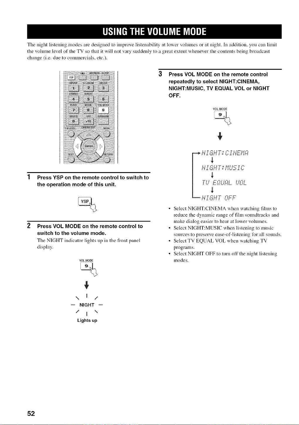
The night listening modes are designed to improve listenability at lower volumes or at night. In addition, you can limit
the volume level of the TV so that it will not vary suddenly to a great extent whenever the contents being broadcast
change (i.e. due to comlnercials, etc.).
Press VOL MODE on the remote control
repeatedly to select NIGHT:CINEMA,
NIGHT:MUSIC, TV EQUAL VOL or NIGHT
OFF.
VOL MODE
%
Press YSP on the remote control to switch to
the operation mode of this unit.
Press VOL MODE on the remote control to
switch to the volume mode.
The NIGHT indicator lights up in the front panel
display.
VOL MODE
\ ] /
-- NIGHT --
/ I \
Lights up
N '.,"U.,H i # i ."i N 1'' Pi_4
] i k LH _LH ] H H
-- ]',i Z ].4M _ ] H.. k.
• Select NIGHT:CINEMA when watching films to
reduce the dynamic range of film soundtracks and
make dialog easier to hear at lower volumes.
• Select NIGHT:MUSIC when listening to nmsic
sources to preserve ease-of-listening for all sounds.
• Select TV EQUAL VOL when watching TV
programs.
• Select NIGHT OFF to turn off the night listening
modes.
52
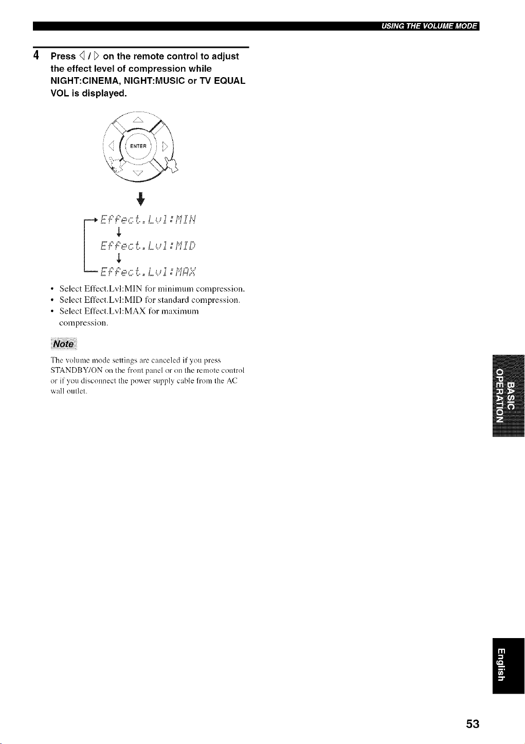
rJ_"_hV[elE;I,l_[e]!#Jj_l_lj_[e]el
Press <_/ _ on the remote control to adjust
the effect level of compression while
NIGHT:CINEMA, NIGHT:MUSIC or TV EQUAL
VOL is displayed.
• Select Effect.Lvl:MIN for minimum compression.
• Select Effect.Lvl:MID for standard compression.
• Select Effect.Lvl:MAX for maximunl
compression.
The volume mode settings are canceled if you press
STANDBY/ON (m the front panel or on the remote control
or if you disconnect the power supply cable l?om the AC
wall outlet.
I
53
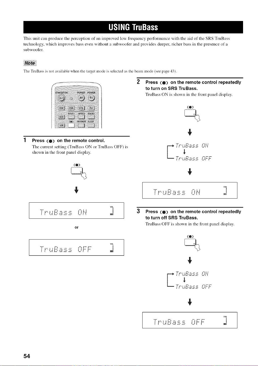
This unit can produce the perception of an improved low frequency performance with the aid of the SRS TruBass
technology, which improves bass even without a subwoofer and provides deeper, richer bass ill the presence of a
subwoofer.
The TruBass is not available when the target mode is selected as the beam mode (see page 43).
2 Press (0) on the remote control repeatedly
to turn on SRS TruBass.
TruBass ON is shown in the front panel display.
(®)
Press (0) on the remote control.
The current setting (TruBass ON or TrnBass OFF) is
shown in the front panel display.
rOE
i i'' t...ii2=,:::i;:::.J:::, LJi'i ==
3
rOE
T! 13.iii :iii.:iii.0H _-=
or
rot
i i' ' L,i i2) .:::i2:>i:::. L._i'" i" =:
Press (0) on the remote control repeatedly
to turn off SRS TruBass.
TruBass OFF is shown in the front panel display.
i i .'.qL.:.;'a.3v.£v. .'..:i i
rOE
"T"_.".z__:::_:::_.:::_::: ['i i2"i2"
54
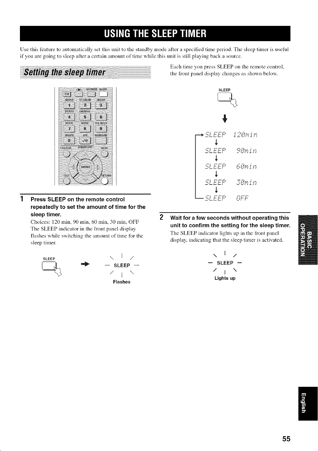
Use this feature to automatically set this unit to the standby mode after a specified time period. The sleep timer is useful
if you are going to sleep after a certain amount of time while this unit is still playing back a source.
Each time you press SLEEP on the remote control,
the front panel display changes as shown below.
Press SLEEP on the remote control
repeatedly to set the amount of time for the
sleep timer.
Choices: 120 rain, 90 rain, 60 rain, 30 rain, OFF
The SLEEP indicator in the front panel display
flashes while switching the amount of time for the
sleep timer.
SLEEP
",, ÷÷*"
.... SLEEP ....
**" i *'**
Flashes
SLEEP
--+5LEEF'
",. i i*,. i*,. £3 "*,3 L,i tv, _ t*",
!,
___,*i £££3 t ¢ t*,. t*,
,=,, _==_==_==_ ,'.Ji i
Wait for a few seconds without operating this
unit to confirm the setting for the sleep timer.
The SLEEP indicator lightsup in the front panel
display, indicating that the sleep tinier is activated.
\ I /
-- SLEEP --
/ I \
Lights up
55
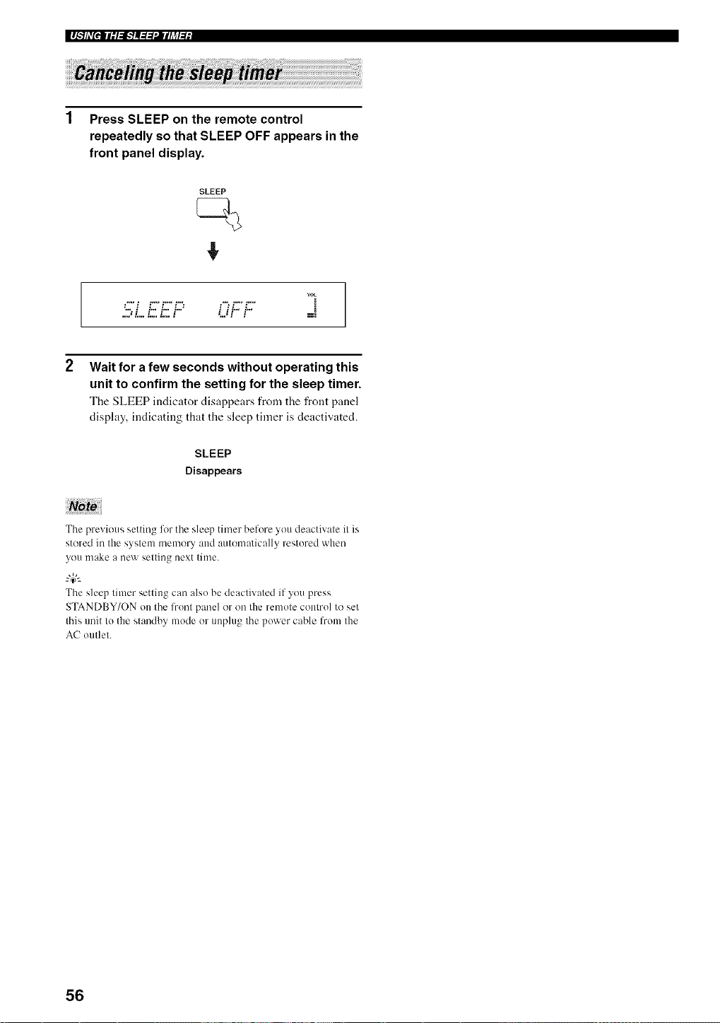
I I._.',lhv[ell l - l,l,.'] !._._ .Jl { h_l ;l l
1 Press SLEEP on the remote control
repeatedly so that SLEEP OFF appears in the
front panel display.
SLEEP
VOL
.................OFF
2 Wait for a few seconds without operating this
unit to confirm the setting for the sleep timer.
The SLEEP indicator disappears from tile front panel
display, indicating that the sleep timer is deactivated.
SLEEP
Disappears
The previous setting liar the sleep timer before you deactivate it is
stored in the system memory and automatically restored when
you make a new setting next time.
The sleep timer setting can also be deactivated if you press
STANDBY/ON on the front panel or on the remote control to set
this unit to the standby mode or unplug the power cable from the
AC outlet.
56
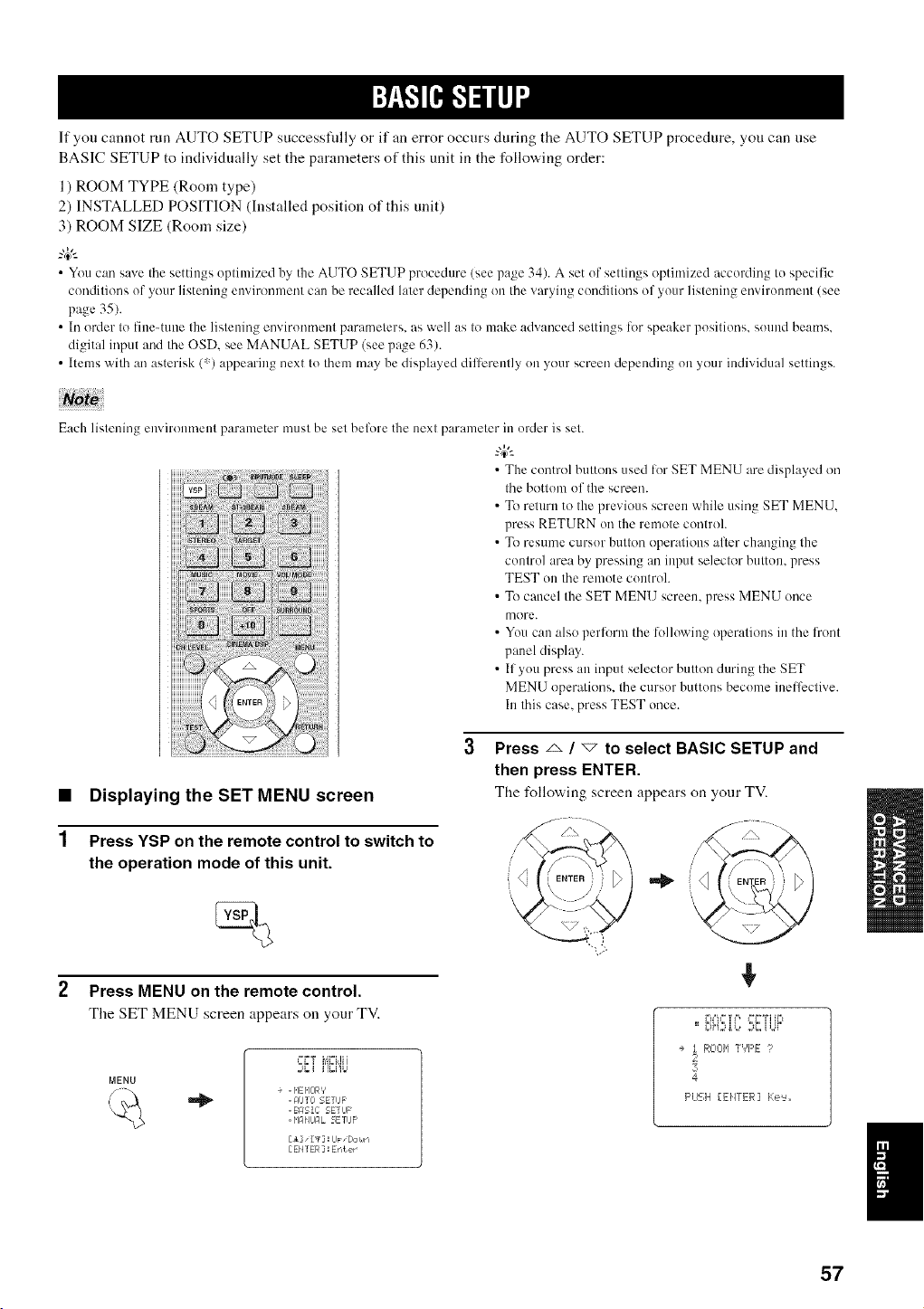
If you cannot run AUTO SETUP successfidly or if an error occurs during the AUTO SETUP procedure, you can use
BASIC SETUP to individually set the parameters of this unit in the following order:
l ) ROOM TYPE (Room type)
2) INSTALLED POSITION (Installed position of this unit)
3) ROOM SIZE (Room size)
--'4:--
• You can save the settings optimized by the AUTO SETUP procedure (see page 34). A set of settings optimized according to specific
conditions of your listening environmm/t can be recalled later depending on the varying conditions of your listening mwiromnent (see
page 35).
• In order to fine-tune the listening mwironment parameters, as well as to make advanced settings lot speaker positions, sound beams.
digital input and the OSD. see MANUAL SETUP (see page 63).
• Items with an asterisk (*) appearing next to them may be displayed dilterently on your screen depending on your individual settings.
Each listening environment parameter must be set belore the next parameter in order is set.
• The control buttons used lor SET MENU are displayed on
the bottom of the screen.
• To return to the previous screen while using SET MENU.
press RETURN on the remote control.
• To resume cursor button operations alter changing the
control area by pressing an input selector button, press
TEST on the remote controh
• To cancel the SET MENU screen, press MENU once
more.
• You can also perlbrm the following operations in the front
panel display.
• If you press an input selector button during the SET
MENU operations, the cursor buttons become inelfcctive.
In this case, press TEST once.
1
Displaying the SET MENU screen
Press YSP on the remote control to switch to
the operation mode of this unit.
Press MENU on the remote control.
The SET MENU screen appears on your TV.
MENU
%
:.,_i i']Ci'b
+ . HEHOR'/
. F4UIO SETIJF
. BASIC 5ETUF'
= _'IFI_IJFIL 5ErUF'
[El" [_']: IJp "Dor#rl
[EHTER]: Er,ter
Press _ / _ to select BASIC SETUP and
then press ENTER.
The I\_llo'a, ing screen appears on yonr TV.
i'u%"q'J', _"q"Wifi't
==_SH2d, L, ::_2_H.ii"
+ t ROOH T','F'E ?
4
F'LEH [EHTER] Ke'=_,,
57
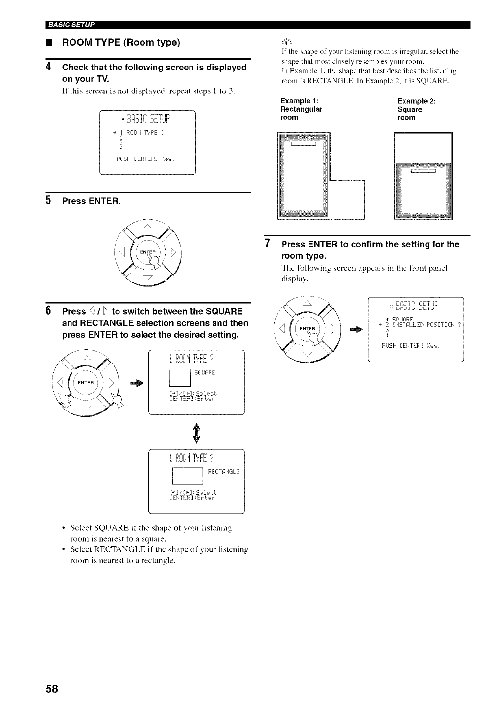
I'=_P/l"l-1-ilq'
• ROOM TYPE (Room type)
4 Check that the following screen is displayed
on your TV.
If this screen is not displayed, repeat steps 1 to 3.
I%%"M'+++++i"?i ti+t
==Zd"t:iU+,, 2+Z U+i+"
÷ 1 ROOI,ITYPE ?
2
3
4
F'LISH[EIqTER] Ke'=_+
Press ENTER.
....... .
6 Press <_/ _>to switch between the SQUARE
and RECTANGLE selection screens and then
press ENTER to select the desired setting.
=_
i _'+'trlM_+'+"_+`'
...... +'i,rZ :'
_ Sg+UIZlRE
D_] ',r _-]_S,=,lect
EEIITER ] ; ErAeJ ....
i rl='='M Tilt+it +
Z i ]i ]i'l li'rr '='
REC:TRIJGL E
D+q 'r+-]_ Select
[ EI4TER ] ; ErAeJ ....
If the shape of your listeuing room is irregular, select the
shape that most closely resembles your room.
In Example 1, the shape that best describes the listening
room is RECTANGLE. In Example 2, it is SQUARE.
Example 1 : Example 2:
Rectangular Square
room room
Press ENTER to confirm the setting for the
room type.
The following screen appears in the front panel
display.
l+t+'u+?++, +++"?i tl+t
==Z,HSi,++,+.SiZ U+,++"
+: S¢!URRE
÷ 2 iHSTRLLED F'OSiTIOH ?
3
4
F'USH {EHTER] Ke'_+
• Select SQUARE if the shape of your listening
roonl is nearest to a square.
• Select RECTANGLE if the shape of your listening
room is nearest to a rectangle.
58
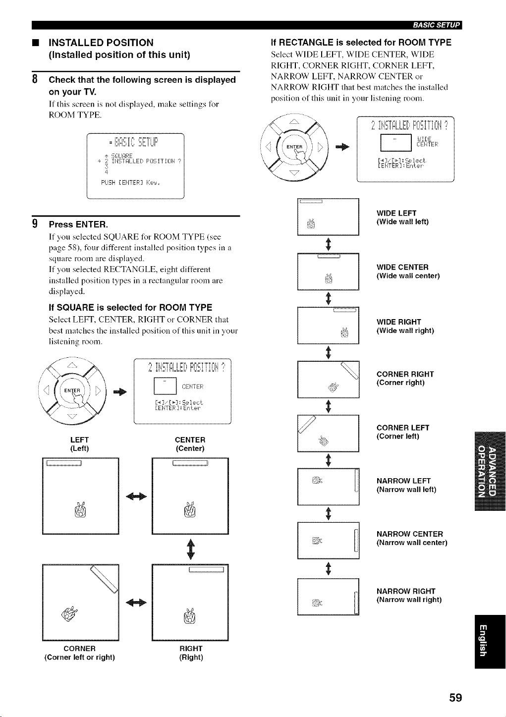
INSTALLED POSITION
(Installed position of this unit)
Check that the following screen is displayed
on your TV.
If this screen is not disphtyed, make settings for
ROOM TYPE.
F'u=u"*?F', Ffi"WIH=t
==DH,:)i b 2i: [ UF
:÷: SG_UPRE
÷ 2 iI,ISTJ_LLEDF'OSiTIOH
3
4
F'LISIH[ENTER] Ke,:_
Press ENTER.
If you selected SQUARE for ROOM TYPE (see
page 58), four different installed position types in a
square morn are displayed.
If you selected RECTANGLE, eight different
installed position types in a rectangular room are
displayed.
If SQUARE is selected for ROOM TYPE
Select LEFT, (.'ENTER, RIGHT or CORNER that
best matches the installed position of this unit in your
listening room.
,=l TLI_%=I i r=F,, FI==I=T_TFILI ,=l
L _i'!:11NLIBb'FL!:qi _L!'! :'
C:EIITER
[ EIqYER ] _En ,*.e_....
LEFT
{Left)
11
CENTER
{Center)
%
CORNER
{Corner left or right)
RIGHT
{Right)
/
i
r_Npl'l_lq
If RECTANGLE is selected for ROOM TYPE
Select WIDE LEFT, WIDE CENTER, WIDE
RIGHT, CORNER RIGHT, CORNER LEFT,
NARROW LEFT, NARROW CENTER or
NARROW RIGHT that best matches the installed
position of this unit in your listening room.
,=l TLI%'%=l i FB, FIe =YY%=ILI ,=l
L _i'!ni NLLib'FL!:4i _L!'I :'
dl[E
C:EMTER
[..] '[_-]= Seie,:t
[ EI/TER ] : En'L e_....
WIDE LEFT
l')_ {Wide wall left)
j WIDE CENTER
/
{Wide wall center)
] WIDE RIGHT
{Wide wall right)
CORNER RIGHT
I_o {Corner right)
CORNER LEFT
{Corner left)
_L_, NARROW LEFT
{Narrow wall left)
;_ 1 NARROW CENTER
_< {Narrow wall center)
t NARROW RIGHT
5,}_. {Narrow wall right)
I
59
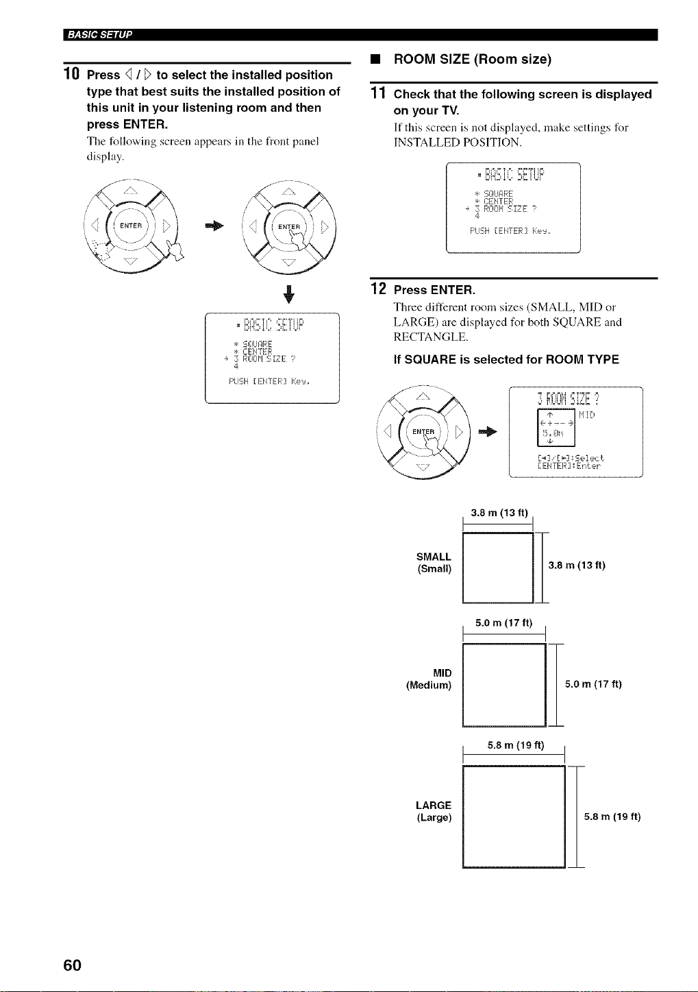
l+_F/pf-'/-'ilq'
10 Press _ / _>to select the installed position
type that best suits the installed position of
this unit in your listening room and then
press ENTER.
The follo_,ing screen appears in the front panel
display.
+
i%%+ _'++, ++I"WI tl+
* S¢_U]:IRE
* C:EHTER
÷ 3 ROOM SIZE 1'
4
PUSH [ENTER] Ke'=u
• ROOM SIZE (Room size)
11 Check that the following screen is displayed
on your TV.
]f this screen is not displayed, make settings for
INSTALLED POSITION.
....... , ,+ ill+.,+
==+2,H,::d,L++::,]::,,+,+
* S¢_UFIRE
+: C:ElfiTER
÷ 3 ROOH SiZE ?
4
PUSH [EHTER] Ke'=u,
12 Press ENTER.
Three different room sizes (SMALL, MID or
LARGE) are displayed for both SQUARE and
RECTANGLE.
If SQUARE is selected for ROOM TYPE
_y? ,'+F,th°+l'i:,s,'-',: :'
iqi ill:+
['_ ] [ _'] _=S e i e,: "I
[ EiITER] _Enter
SMALL
(Small)
3.8 m (13 ft)
iTm
5.0 m (17 ft)
(13 ft)
MID
(Medium)
5.0 m (17 ft)
LARGE
(Large)
5.8 m (19 ft) I
5.8 m (19 ft)
60
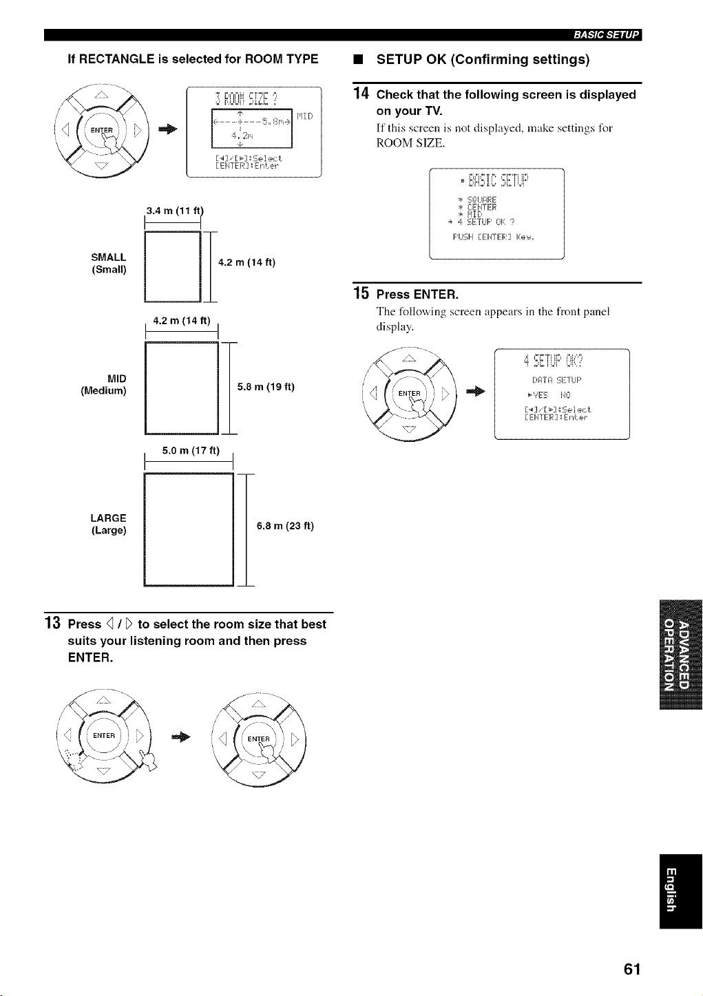
• SETUP OK (Confirming settings)
14 Check that the following screen is displayed
on your TV.
If this screen is not displayed, make settings for
ROOM SIZE.
t3.4 m (11 ft I
MID
(Medium)
LARGE
(Large)
4.2 m (14 ft)
5.0 m (17 ft)
15.8 m (19 ft)
6.8 m (23 ft)
* S¢!LIPRE
* CEIqTER
* HID
÷ 4 SETUP OK ?
F'USH [EHTER] i:e'=,,,
15 Press ENTER.
The following screen appears in the front p:mel
display.
_¢ PI'TI ti" J'H,%
.... i ........ ,, ,,
DIZITlZlSETUP
b','ES iqCl
[._],'[ _] _Sel ec _.
[ EHTER ] ; Enler
13 Press q / _>to select the room size that best
suits your listening room and then press
ENTER.
/ /\ "
I
61
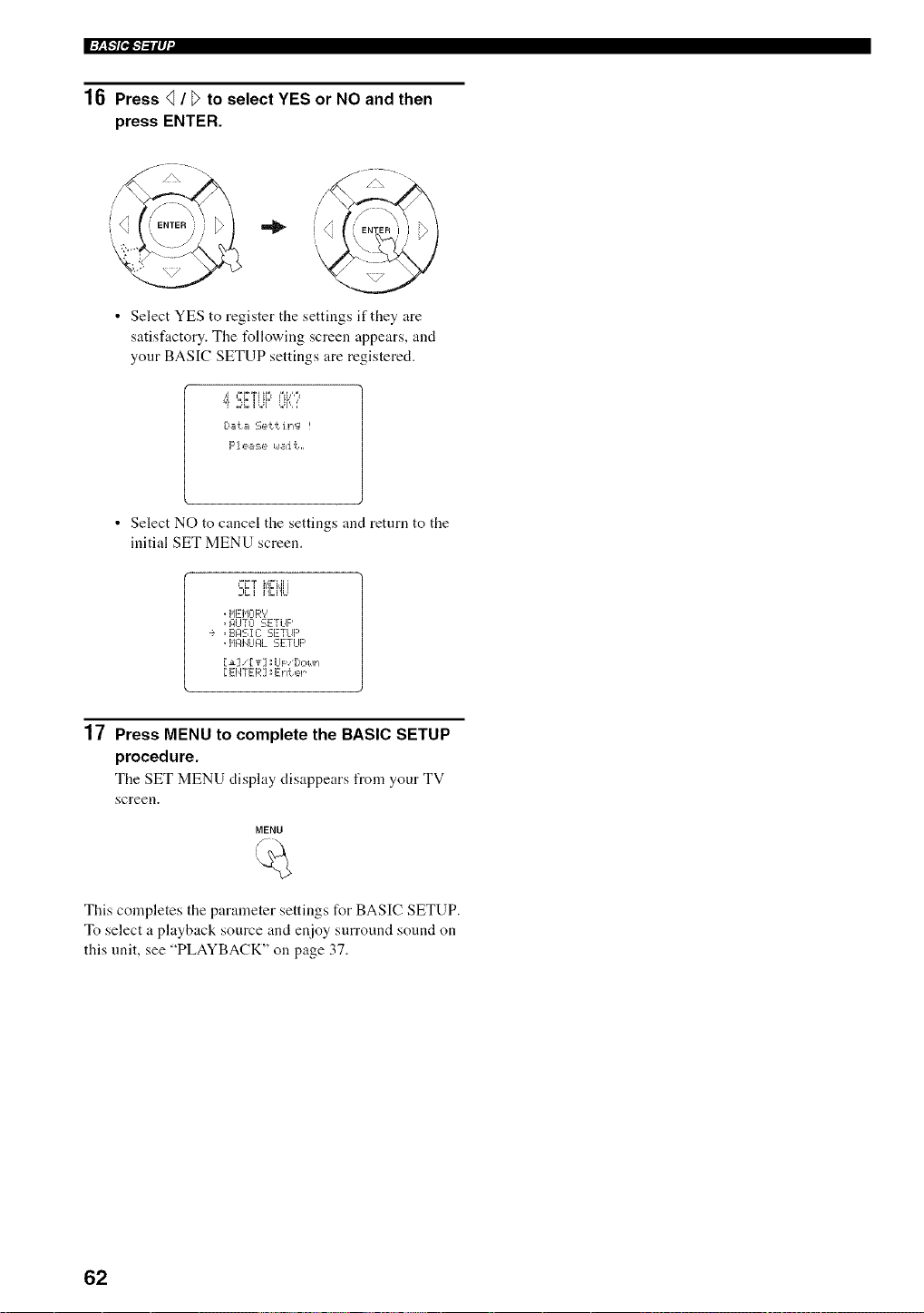
l:_F1Pi:b'ilq'
16 Press _ / _ to select YES or NO and then
press ENTER.
/\ --- _./\ -- .
.22
• Select YES to register the settings if they are
satisfactory. The t_llowing screen appears, and
your BASIC SETUP settings are registered.
• Select NO to cancel the settings and return to the
initial SET MENU screen.
._ _ i'E!',']
,HEHCIR'?
,RUTCI SETUP
•_ ,EII:ISIC:SETUP
,HFII4LII31.SETLIp
[EI4TER] _Erl'_ er
17 Press MENU to complete the BASIC SETUP
procedure.
The SET MENU display disappears from your TV
screen.
MENU
This completes the parameter settings for BASIC SETUP.
To select a playback source and enjoy surround sound on
this unit, see "PLAYBACK" on page 37.
62
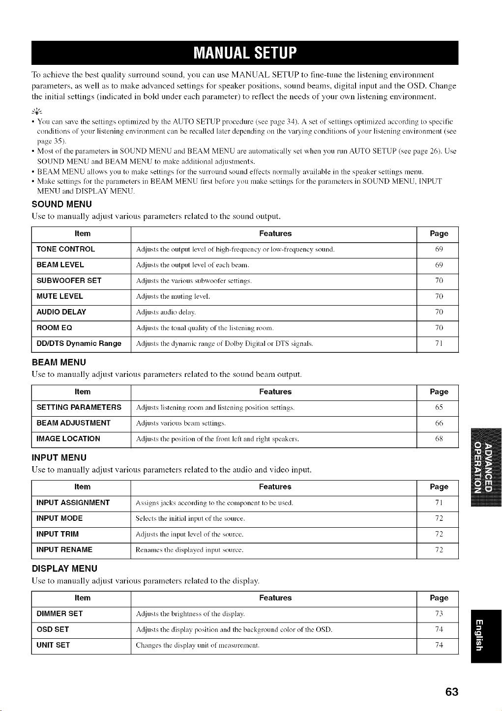
To achieve the best quality snrround sound, yon can use MANUAL SETUP to fine-tune the listening environment
parameters, as v,.ell as to make advanced settings t_r speaker positions, sonnd beams, digital input and the OSD. Change
the initial settings (indicated in bokt under each parameter) to reflect the needs of yonr own listening environment.
_.,#._
• You can save the settings optimized by the AUTO SETUP procedure (see page 34). A set of settings optimized according to specific
conditions of your listening environmm/t can be recalled later depending on the varying conditions of your listening mwiromnent (see
page 35).
• Most of the parameters in SOUND MENU and BEAM MENU are automatically set when you mn AUTO SETUP (see page 26). Use
SOUND MENU and BEAM MENU to make additional ac[justments.
• BEAM MENU allows you to make settings lor the surround sound eltects normally available in the speaker settings inenu.
• Make settings for the parameters in BEAM MENU first before you make settings for the parameters in SOUND MENU. INPUT
MENU and DISPLAY MENU.
SOUND MENU
Use to manually adjust various parameters related to tile souM output.
Item Features Page
TONE CONTROL Adjusts the output level of high-frequency or low-frequency sound. 69
BEAM LEVEL Adjusts the output level of each beam. 69
SUBWOOFER SET Adjusts the various subwoofcr settings. 70
MUTE LEVEL Adjusts the muting level. 70
AUDIO DELAY Adjusts audio delay. 70
BOOM EQ Adjusts Ihe tonal quality of the listening room. 70
DD/DTS Dynamic Range Adjusts the dynamic range of Dolby Digital or DTS signals. 71
BEAM MENU
Use to manually adjust various parameters related to tile sound beam output.
Item Features Page
SETTING PARAMETERS Adjusts listening room and listening position settings. 65
BEAM ADJUSTMENT Adjusts various beam settings. 66
IMAGE LOCATION Adjusts the position of the front left and right speakers. 68
INPUT MENU
Use to manually adjust various parameters related to the audio and video input.
Item Features Page
INPUT ASSIGNMENT Assigns jacks according to the component to be used. 71
INPUT MODE Selects the initial input of the source. 72
INPUT TRIM Adjusts the input level of the source. 72
INPUT RENAME Renames the displayed input source. 72
DISPLAY MENU
Use to manually adjust various parameters related to tile display.
Item Features
DIMMER SET Adjusts the brightness of the disph,y.
OSD SET Adjusts the display position and the background color of the OSD.
UNIT SET Changes the display unit of measurement.
Page
74
74
63
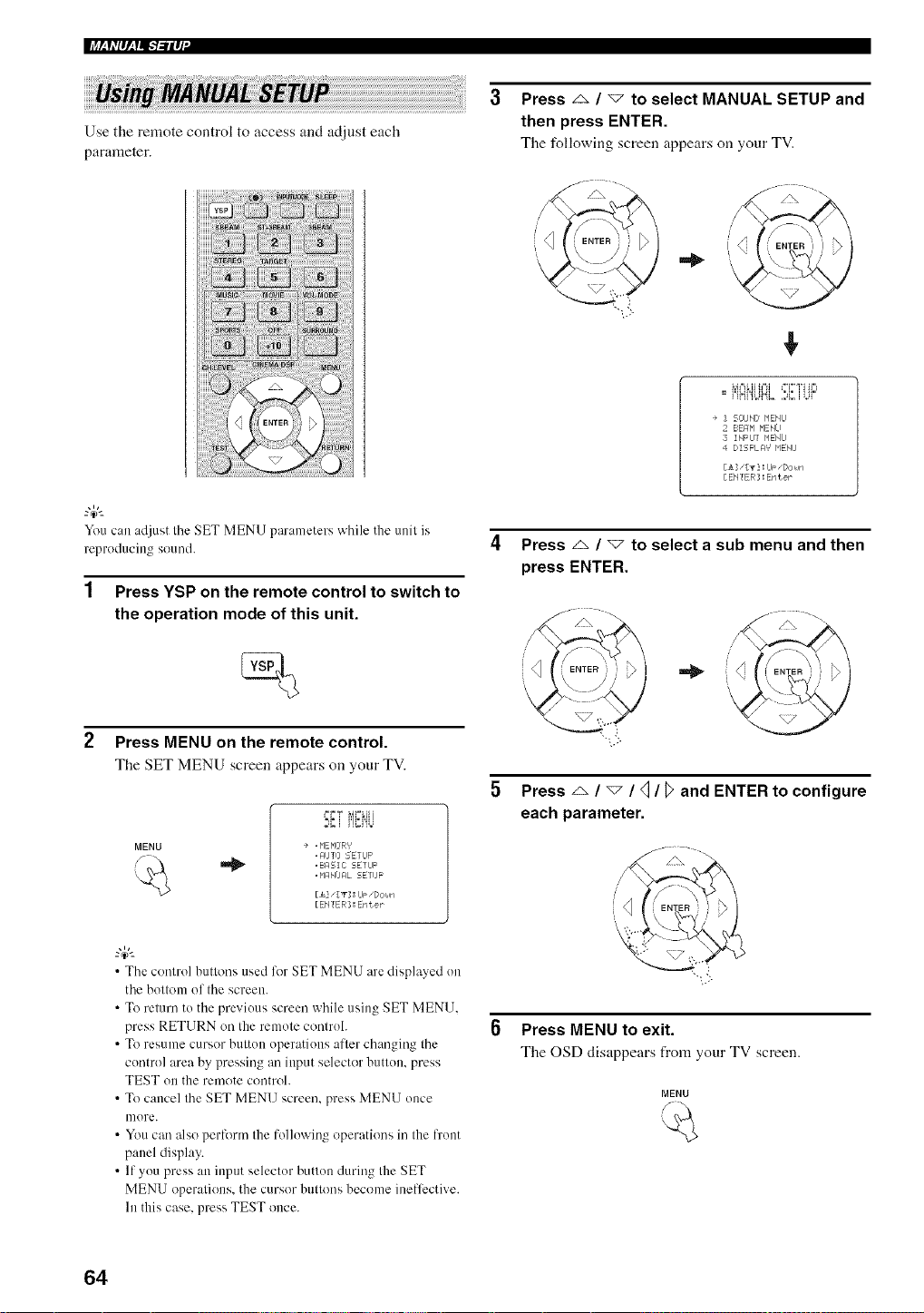
+++
Use the remote control to access and adjust each
parameter.
You can adjust the SET MENU parameters while the unit is
reproducing sound.
1 Press YSP on the remote control to switch to
the operation mode of this unit.
2 Press MENU on the remote control.
The SET MENU screen appears on your TV.
MENU
+=F=_ +,4Fml+i
-,_ + i,li=i,_h
÷ , NENEIR'¢
, AIJTO SETUP
,BAEIC SETUF
. NAMJFIL SETUP
[_.3 " [T] : IJ_ "Dc,+_¢i
[ENTER] : Eraer
• The control buttons used for SET MENU are displayed on
the bottom of the screen.
• To return to the previous screen while using SET MENU,
press RETURN on the remote controh
• To resume cursor button operations after changing the
control area by pressing an input selector button, press
TEST on the rmnote control.
• To cancel the SET MENU screen, press MENU once
more.
• You can also perform the following operations in the t)'ont
panel display.
• If you press an input selector button during the SET
MENU operations, the cursor buttons become inefli_ctive+
In this case, press TEST once.
Press _ / v to select MANUAL SETUP and
then press ENTER.
Tile follov4ng screen appears cm your TV.
+
-, t.">
+
.. I'='III},INI_I +.,I., =+++
" + !1"+I%,++'%. ,,,a,. I +J+
+ SOUN[J NENIJ
BEr/N NENU
INFIJT NENU
DISFL _:1'¢ _'IENU
[A] "[_3 : IJF "[Joke]
[ ENTEB ] : Enter
Press _ / _ to select a sub menu and then
press ENTER.
5 Press _ / v / <] / _ and ENTER to configure
each parameter.
Press MENU to exit.
Tile OSD disappears from your TV screen.
MENU
64
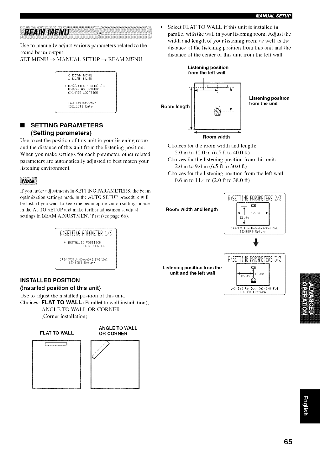
Use to manually adjust various parameters related to the
sound beam output.
SET MENU > MANUAL SETUP _', BEAM MENU
,"l FFML4 M.'"LI i
L E_gN,,','i2/,t
+ FI:SETTIHG F'RRRP1ETERS
B>BEAM ADJIJSTMEHT
C> I_'IAGE LI]CAT II]_I
[_] "[_] :IJp "[/Ol,m
[5ELEI T ] :Enter
• SETTING PARAMETERS
(Setting parameters)
Use to set tile position of this unit in your listening room
and the distance of this unit from the listening position.
When you make settings for each parameter, other related
parameters are automatically adjusted to best match your
listening environment.
lfyou make a([justments in SETTING PARAMETERS, the beam
optimization settings made in the AUTO SETUP procedure will
be lost, If you want to keep the beam optimization settings made
in the AUTO SETUP and make further at[iustnlmlts, adjust
settings in BEAM ADJUSTMENT first (see page 66),
EA,==r="_TT LIF, FI=_IFIFj!,_.,=T F F
÷ IHSTFILLED POSITIOH
..... FLAT TO I,JRLL
[ EHTER ] : Ret Urrl
INSTALLED POSITION
(Installed position of this unit)
Use to adjust the installed position of this unit.
Choices: FLAT TO WALL (Parallel to wall installation),
ANGLE TO WALL OR CORNER
(Corner installation)
FLAT TO WALL
ANGLE TO WALL
OR CORNER
_Sh'p,_f=I,-1-'llq'
Select FLAT TO WALL if this unit is installed in
parallel with the wall in your listening room. Adjust the
width and length of your listening room as well as the
distance of the listening position from this unit and the
distance of the center of this unit from the left wall.
Listening position
from the left wall
Room length ________
Room width
Choices t_r the room "a,idth and length:
2.0 m to 12.0 m (6.5 ft to 40.0 It)
Choices t_r the listening position from this unit:
2.0 m to 9.0 in (6.5 ft to 30.0 It)
Choices for the listening position from the left wall:
0.6 in to 11.4 m (2.0 ft to 38.0 ft)
Listening position
from the unit
Room width and length
F/',=3.'2TT?i,i2 FIFjrIML_r='cFr,=='=1,I_
z_X,E
y' ]
[_3 _[g] :LI_ _[/Or_IrrgI_3" [b] !Se I
[£#I'fE R ] :Return
¢
Listening position from the
unit and the left wall
F',,==FTT?LI =, FI==J_I==IL_FTFFI= T ,1'_
N,,'2_ i i ii'!,2FNi',IN,l_ii_l,:_,fIll,111
]
[EHTER : RetuPn
I
65
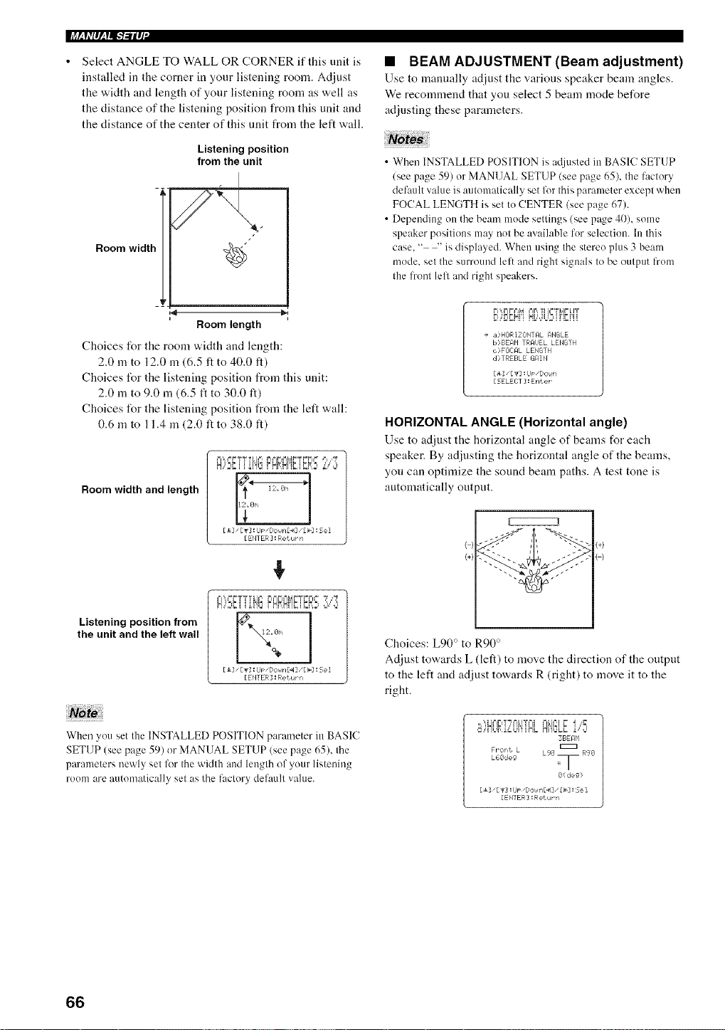
li+_h'P,_l,11-+-'il_I"
Select ANGLE TO WALL OR CORNER if this unit is
installed in the corner in your listening room. Adjust
the width and length of your listening morn as well as
the distance of the listening position from this unit and
the distance of the center of this unit from the left wall.
Listening position
from the unit
Room widtl"
,4
Room length
Choices for tile morn width and length:
2.0 m to 12.0 m (6.5 ft to 40.0 ft)
Choices l\_r the listening position from this unit:
2.0 m to 9.0 m (6.5 ft to 30.0 ft)
Choices l\_r the listening position from the left wall:
0.6 m to 11.4 m (2.0 ft to 38.0 It)
Room width and length
Listening position from
the unit and the left wall
+
pi,,,==r+,"('¢TL ==, r"i==t+l==iM.,"=,-(r=r.l==
7+7
H,C',li i ihi2 r,HffHi'!',li U_,},:,',"',:,,
. 3m
%
Eli _[T] : Up _Dokln£_l],[b] :5e I
[EblTER] : Ret urr,
When you set the INSTALLED POSITION parameter in BASIC
SETUP (see page 59) or MANUAL SETUP (see page 65). the
parameters newly set lbr the width and length of your listening
room are autonmtically set as the factory default vahm.
• BEAM ADJUSTMENT(Beam adjustment)
Use to manually adjust the various speaker beam angles.
We recommend that you select 5 beam mode before
adjusting these parameters.
• When INSTALLED POSITION is atlinsted in BASIC SETUP
(see page 59) or MANUAL SETUP (see page 65), the factory
default value is automatically set for this parameter except when
FOCAL LENGTH is set to CENTER (see page 67).
• Depending on the beam mode settings (see page 40), some
speaker positions may not be available for selection. In this
case. " -' is displayed. When using the stereo plus 3 beam
mode. set the surround left and right signals to be output from
the front lell and right speakers.
rl',,r r=+%_==it+,?+':=T+,!r%lT
E_,,E,gH,, HL,'dt+!2,ii'lgi'ii
+ a)HORIZONTI:IL ANGLE
B,>BEI:IH TRAt)EL LENG'rH
,s>FmML LENGTH
d>TREE=LE G_IIN
[i] ,[ _] :IJp,Dol,Jn
[SELECT ]:Enter
HORIZONTAL ANGLE (Horizontal angle)
Use to adjust the horizontal angle of beams for each
speaker. By adjusting the horizontal angle of the beams,
you can optimize the sound beam paths. A test tone is
automatically output.
( : :+)
(+)
Choices: L90 ° to R90 °
Adjust towards L (left) to move the direction of the output
to the left and adjust towards R (right) to move it to the
right.
=',,H=%'=iT"_+=iLI%=II ++ILj=",IY I ,_
,+%+Mt+,m,i,,:St++l'!+HLN'ItSLBi,"d
3BEAP'I
FPoh_ L
L.66deg L96 _ RgO
I
8(deg>
[_] IT] :IJP +[/ol IR[_1 ] +[I_] : Sel
[ENTER] :Ret uPn
66
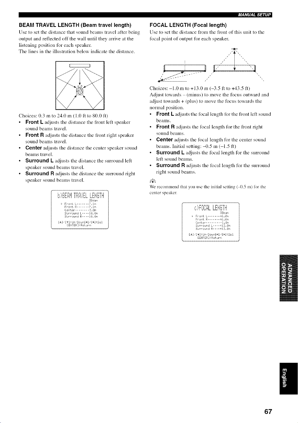
BEAM TRAVEL LENGTH (Beam travel length)
Use to set tile distance that sound beams travel after being
output and reflected off the wall until they arrive at the
listening position for each speaker.
The lines in the illustration below indicate the distance.
Choices: 0.3 in to 24.0 m (1.0 ft to 80.0 ft)
Front L adjusts the distance the front left speaker
sound beams travel.
Front R adjusts the distance the t_ont right speaker
sound beams travel.
Center adjusts the distance the center speaker sound
beams travel.
Surround L adjusts the distance the surround left
speaker sound beams travel.
Surround R ac[iusts the distance the surround right
speaker sound beams travel.
38e _r.i
+ Front L ....... ?.In
Front R....... 7. In
Center .......... 3.8r./
Su_r,_urd L.... 10. Qr.i
=Cur r ol_rll:t R.... I0. Or.i
[ ENTER ] : Return
FOCAL LENGTH (Focal length)
Use to set tile distance from tile front of this unit to tile
focal point of output for each speaker.
Choices: 1.0 m to +13.0 m ( 3.5 ft to +43.5 ft)
Adjust towards (minus) to move the focus outward and
adjust towards + (plus) to move the focus towards the
normal position.
• Front L adjusts the focal length for the front left sound
beams.
• Front R adjusts the focal length for the front right
sound beams.
• Center adjusts the focal length for the center sound
beams. Initial setting: 4).5 m ( 1.5 ft)
• Surround L adjusts the focal length for the surround
left sound beams.
• Surround R adjusts the focal length for the surround
right sound beams.
We recommend that you use the initial setting (_).5 m) for the
center speaker.
,* 'H.,III'III I l.,_,II,211.l
1,I'M Ji,i_J.i'i"!i,. I,&,V!_I_ If I
3Se ar,i
+ Frorit L ....... +6=Or, i
Fr oriL R....... +6. Or,i
Cerrter ........... I .On
Su_ _ ou_id L= .. =+13. Or,i
51atr OlarldR, ==, +I 3, 0r'l
[_i [gi :lJ_ "[/OhJti_] •[_i : Se I
[EMl ER :Return
I
67
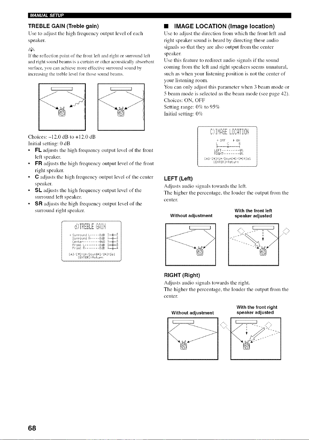
TREBLE GAIN (Treble gain)
Use to adjust tile high frequency output level of each
speaker.
4+'--
If tile reflection pohlt of the Kont left and right or surround left
and right sound beams is a curtain or other acoustically absorbent
surlhce, you can achieve more etfcctive surround sound by
increasing the treble level for those sound beams+
EZEZEZZ/
• IMAGE LOCATION (Image location)
Use to adjust tile direction from which tile front left and
right speaker sOUnEt is heard by directing these audio
signals so that they are also output from tile center
speaker.
Use this feature to redirect audio signals if the sound
coming from the left and right speakers seems unnatural,
such as when your listening position is not the center of
your listening room.
You can only adjust this parameter when 3 beam mode or
5 beam nlode is selected as the beam mode (see page 42).
Choices: ON, OFF
Setting range: 0% to 95%
Initial setting: 0%
Choices: -12.0 dB to +12.0 dB
Initial setting: 0 dB
• FL adjusts the high frequency output level of the front
left speaker.
• FR adjusts the high frequency output level of the front
right speaker.
• C adjusts the high frequency output level of the center
speaker.
• SL adjusts the high frequency output level of the
surround left speaker.
• SR adjusts the high frequency output level of the
surround right speaker.
OFF _ ON
L C R
!-...-..-.-+l +....- .- q
LEFT .......... _3;_
RIGHT ......... 8:,"
[ ENTER _ : Return
LEFT (Left)
Adjusts audio signals towards the left.
The higher the percentage, the louder the output from the
center.
Without adjustment
With the front left
speaker adjusted
RIGHT (Right)
Ac[iusts audio signals towards the right.
The higher the percentage, the louder the output from the
center.
Without adjustment
With the front right
speaker adjusted
68
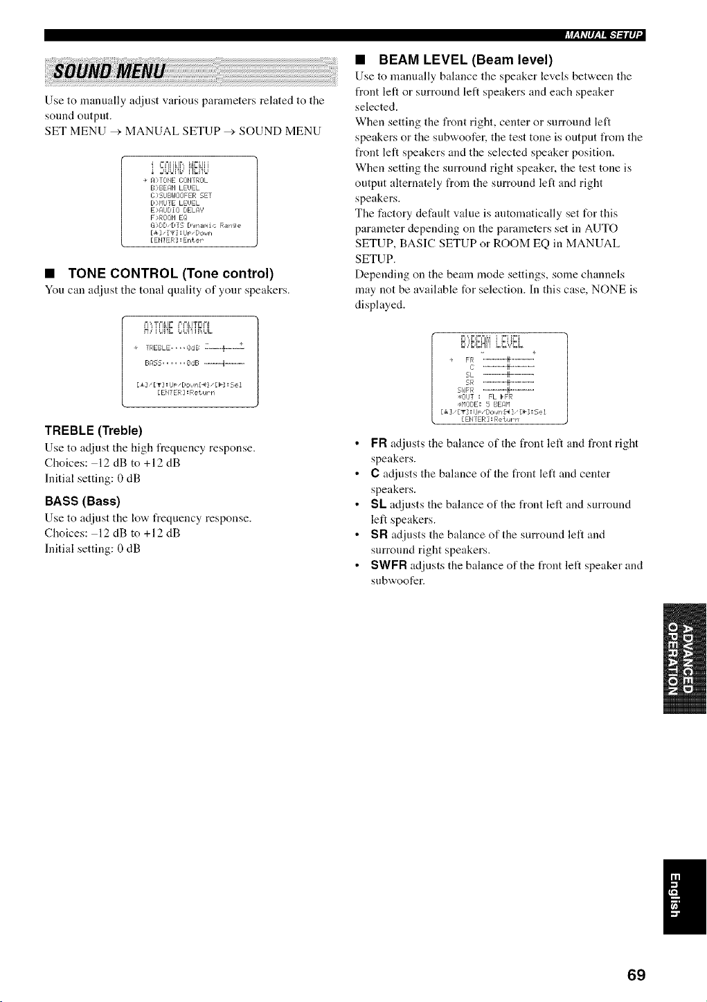
Use to manually adjust various parameters related to the
sound output.
SET MENU > MANUAL SETUP _'. SOUND MENU
i SOUi{:iiEHU
+ A>TIDHE I]OHTROL
B>BE@I LEUEL
C ?SIJBi_JOOFER SET
D q'liJ] E LEUEL
E 'AUDIO DELA' '
F :,ROOHEQ
13 ,DD'DT5 D'Jrlar, liC Range
[_3" [._3 :IJF "DOI6FI
[EH1ER :Erl_eF
• TONE CONTROL (Tone control)
Youc:ma_[iustthetonalquality of your speakers.
M,,, ,=F I= I=,I=ILI'_FI==I!
E;_q2S...... 8dE; ...... 4 ......
Eli [T] :lip "tOi in{_4]"[_']: Se 1
[ EHT ER ] : R etiar rl
TREBLE (Treble)
Use to adjust the high frequency response.
Choices: 12 dB to +12 dB
Initial setting: 0 dB
BASS (Bass)
Use to adjust the lov,, frequency response.
Choices: 12 dB to +12 dB
Initial setting: 0 dB
• BEAM LEVEL (Beam level)
Use to manually bahmce the speaker levels between the
front left or surround left speakers and each speaker
selected.
When setting the front right, center or surround left
speakers or the subwoofer, the test tone is output from the
front left speakers and the selected speaker position.
When setting the surround right speaker, the test tone is
output alternately from the surround left and right
speakers.
The factory default value is antomatically set for this
parameter depending on the parameters set in AUTO
SETUP, BASIC SETUP or ROOM EQ in MANUAL
SETUP.
Depending on the beam mode settings, some channels
may not be available for selection. In this case, NONE is
displayed.
,.=,,,,."BN,, LUd[].,,
]
+ FR .........+---E
i: ......... b........
SL ...... -}H .....
5R ......._ ......
51JFR i----_-----
tlZillT I FL _FR
@lODE: 5 BEAM
[Jk ], [T] ! I1_" _/oI4_l_ ], [_-] I 5e i
[EHYER]:Returrr
• FR adjusts the balance of the front left and front right
speakers.
• C adjusts the balance of the front left and center
speakers.
• SL adjusts the balance of the front left and surround
left speakers.
• SR adjusts the balance of the surround left and
surround right speakers.
• SWFR adjusts the balance of the front left speaker and
subwoofer.
I
69
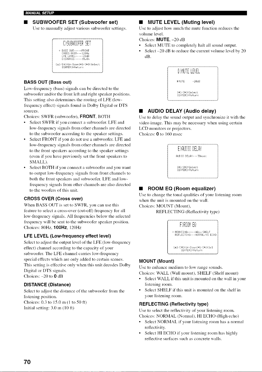
• SUBWOOFER SET (Subwoofer set)
Use to nlanually adjust various su['rwoofer settings.
F,',, ==i 'P"I JF ==FF r +=FT
=,,,2.Ii+,,J=+FF+I,+%i
÷ BASS OIJT ..... FRONT
CROSS OUER... 128Hz
LFE LE'JEL ..... 2@dB
D IST_:IHCE ..... I5. @r',
[i] '[_] : LIp "Down_ ] "[hi : Se I eci
[EH] ER]:RetuP n
BASS OUT (Bass out)
Lov+'-t_equency (bass) signals can be directed to the
subwoofer and/or the front left and right speaker positions.
This setting also determines the routing of LFE (low-
frequency effect) signals found in Dolby Digital or DTS
sonrces.
Choices: SWFR (subwoofer), FRONT, BOTH
• Select SWFR if you connect a subwoofer. LFE and
low-frequency signals from other channels are directed
to the subwoofer according to the speaker settings.
• Select FRONT if you do not use a subwoofer. LFE and
low-frequency signals from other channels are directed
to the front speakers according to the speaker settings
(even if you have previously set the front speakers to
SMALL).
• Select BOTH if you connect a subwoofer and you want
to output low-frequency signals from front channels to
both the front speakers and snbwoofer. LFE and low-
frequency signals from other channels are also directed
to the woofers of this unit.
CROSS OVER (Cross over)
When BASS OUT is set to SWFR, you can use this
feature to select a cross-over (cut-off) frequency for all
low-frequency signals. All freqnencies below the selected
t_equency will be sent to the subwoofer speaker position.
Choices: 80Hz, 100Nz, 120Hz
LFE LEVEL (Low-frequency effect level)
Select to adjust tile uutput level ufthe LFE (low,-freqnency
effect) channel according to the capacity of your
subwoofer. The LFE channel carries low-frequency
special effects which are only added to certain scenes.
This setting is effective only when this unit decodes Dolby
Digital or DTS signals.
Choices: -20 to 0 dB
DISTANCE (Distance)
Select to adjust the distance of the subv+oofer from the
listening position.
Choices: 0.3 to 15.0 in (1 to 50 ft)
Initial setting: 3.0 m (10 ft)
• MUTE LEVEL (Muting level)
Use to adjust how, much the nmte fnnction reduces the
volnme level.
Choices: MUTE, -20 dB
• Select MUTE to completely halt all sound output.
• Select -20 dB to reduce the current volume level by 20
dB.
H'IlJTE 28dB
['_3" [_1 : 5el ect
[ENTER ] : Rebut n
• AUDIO DELAY (Audio delay)
Use to delay the sound output and synchronize it with the
video image. This may be necessary when using certain
LCD monitors or projectors.
Choices: 0 to 160 msec
P=',,FjIIF+,TF F,,,"=II=J I
F ,+NI Ii,' 11 ]
........... I,'FI i_i
AUDIO DELAY... 3@r,,sec
[._]"£b] : 5el e,:t
[ENTER :Return
• ROOM EQ (Room equalizer)
Use to change the tonal qualities of your listening room
when the unit is mounted on the wall.
Choices: MOUNT (Mount),
REFLECTING (Reflectivity type)
MOUNT (Mount)
Use to enhance medium to lov+ range sounds.
Choices: WALL (Wall mount), SHELF (Shelf mount)
• Select WALL if this unit is mounted on the wall in your
listening room.
• Select SHELF if this unit is mounted on the shelf in
your listening room.
REFLECTING (Reflectivity type)
Use to select the reflectivity of your listening room.
Choices: NORMAL (Normal), HI ECHO (High echo)
• Select NORMAL if your listening room has a nonmtl
reflectivity.
• Select HI ECHO if your listening room has highly
reflective surfaces such as concrete walls.
70
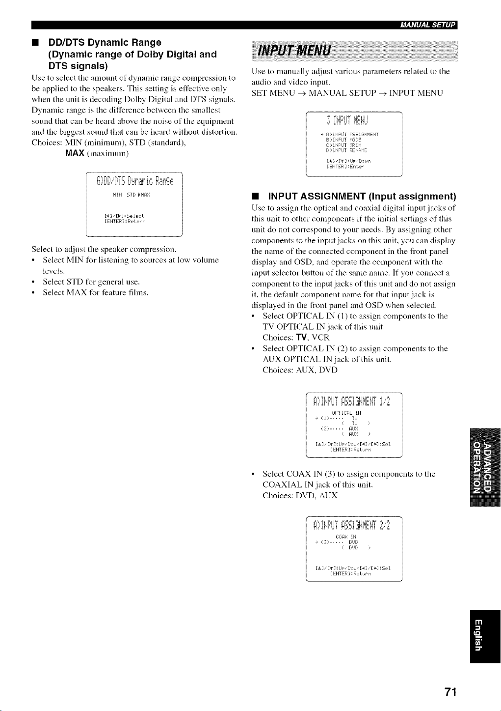
• DD/DTS Dynamic Range
(Dynamic range of Dolby Digital and
DTS signals)
Use to select tile amount of dynamic range compression to
be applied to the speakers. This setting is effective only
when the unit is decoding Dolby Digital and DTS signals.
Dynamic range is the difference between the smallest
sound that can be heard above the noise of the equipment
and the biggest sound that can be heard without distortion.
Choices: MIN (minimum), STD (standard),
MAX (maxinmm)
+4h,++,_+,l,.+'l..-ilq
Use to nmnually adjust various parameters related to the
audio and video input.
SET MENU > MANUAL SETUP _ INPUT MENU
Ti@iff_._min
+ A,INFIJT ASSiGNMEblT
B:_INFUT HODE
C>INPLfT T F¢I P'I
D> INPIJ] RENAHE
[4&]"[_] : IJp"DOWrl
[ EHTER ] : Enter
HIH 5TD H'IA;;
[ENTER] : Reterrl
Select to adjust the speaker compression.
Select MIN for listening to sources at low volume
levels.
Select STD for general use.
Select MAX for feature films.
• INPUT ASSIGNMENT (Input assignment)
Use to assign the optical and coaxial digital input jacks of
this unit to other components if the initial settings of this
unit do not correspond to your needs. By assigning other
components to the input jacks on this unit, you can display
the name of the connected component in the front panel
display and OSD, and operate the component with the
input selector button of the same name. If you connect a
component to the input jacks of this unit and do not assign
it, the def:tnlt component name for that input jack is
displayed in the front panel and OSD when selected.
• Select OPTICAL IN (1) to assign components to the
TV OPTICAL IN jack of this unit.
Choices: TV, VCR
• Select OPTICAL IN (2) to assign components to the
AUX OPTICAL IN jack of this unit.
Choices: AUX, DVD
+=J',,,"PLJP"I+I_ CJ=%=T¢,H ,4r%lT _ ,,,=l
H,,'ii'!FLi+ ,x;,}it_l'!i'lD'4i i,"£
OFT IITAL IF4
+ ':] 1 ;...... TI)
( TI,I >
(2) ..... AIJI;
( AfJX )
[i]_ [T] : LIp "Oown£_4] "[ I_-7: 5el
[ EtITER ] : Rei ur r,
• Select COAX IN (3) to assign components to the
COAXIAL IN jack of this unit.
Choices: DVD, AUX
171)A: ; IN
+ ': 3 > ..... tI) t
( DI,J [/ /
[&]_ [T] i U P" OcJi,Jr'l[_4]"[ _'2! 5el
[ EH]ER ] : Return
71
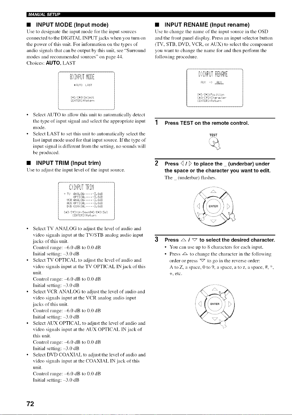
li+_h,I_,lll.-b-il_I"
• INPUT MODE (Input mode)
Use to designate the input mode for tile input sources
connected to the DIGITAL INPUT jacks when you turn on
the power of this unit. For information on the types of
audio signals that can be output by this unit, see "Surround
modes and reconnnended sources" on page 44.
Choices: AUTO, LAST
rl',,'rUt'l+i'r MN[)F
E+,,+_I'£Ul .....
b AUTI] LAST
[._]"[b]: Select
[EH] ER] : Ret ern
• INPUT RENAME (Input rename)
Use to ch;mge the n;une of the input source in the OSD
and the front panel display. Press an input selector button
(TV, STB, DVD, VCR, or AUX) to select the component
you want to change the name for and then perform the
following procedure.
i_,,',,,,=i Ii'il 'T i=ii=L i=_ip,41=
L,,Ai',Fq?,M,Mi'!Hi'IE
Af]bl -> ,_AIJ_
[_7 _[b] : Fos it ion
[i ],[v] :ihar_cteP
[EHTER] :Return
Select AUTO to allow this unit to automatically detect
the type of input signal and select the appropriate input
mode.
Select LAST to set this unit to automatically select the
last input mode used for that input source. If the type of
input signal is different from the setting, no sounds will
be produced.
• INPUT TRIM (Input trim)
Use to at[just the input level of the input source.
C)iHF'LiTTRIM
+ Ti,i AHALCiG ...... 3_SdB
IIF'T I IrAL ..... 5+ 8IJB
i,iOR AHRLOG ...... .8dB
Af_Ii[ OFTICAL ..... 3. SdB
DUD iTi]A: : IAL.... -. 8dB
E±] E_3 =U_ "DoHn £_3 "£_'3 : Se 1
[EH] ER] :Return
• Select TV ANALOG to adjust the level of audio and
video signals input at the TV/STB analog audio input
jacks of this unit.
Control range: 6.0 dB to 0.0 dB
Initial setting: 3.0 dB
• Select TV OPTICAL to adjust the level of audio and
video signals input at the TV OPTICAL IN jack of this
unit.
Control range: -6.0 dB to 0.0 dB
Initial setting: -3.0 dB
• Select VCR ANALOG to adjust the level of audio and
video signals input at the VCR analog audio input
jacks of this unit.
Control range: 6.0 dB to 0.0 dB
Initial setting: 3.0 dB
• Select AUX OPTICAL to adjust the level of audio and
video signals input at the AUX OPTICAL IN jack of
this unit.
Control range: -6.0 dB to 0.0 dB
Initial setting: -3.0 dB
• Select DVD COAXIAL to adjust the level of audio and
video signals input at the COAXIAL IN jack of this
unit.
Control range: 6.0 dB to 0.0 dB
Initial setting: 3.0 dB
1 Press TEST on the remote control.
TEST
Press q / _ to place the _ (underbar) under
the space or the character you want to edit.
The _ (underbar) flashes.
Press _ / _7 to select the desired character.
• You can use up to 8 characters for each input.
• Press z_ to change the character in the following
order or press _ to go in the reverse order:
A to Z, a space, 0 to 9, a space, a to z, a space, #, *,
+, etc.
72
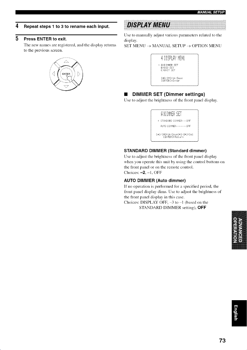
4
5
Repeat steps 1 to 3 to rename each input.
Press ENTER to exit.
Tile ne'a, names are registered, and the display returns
to the previous screen.
+4h'p,_f=IFl-.'ilq
Use to manually ac[iust various parameters related to the
display.
SET MENU _'. MANUAL SETUP _ OtYFION MENU
_' b,T==F41 +=_l _,4FLI'
L,'iE:FLM'i' i'}_iiL]
+ M,DIr'IP1ER SET
B>OSD SET
I >IJNIT SET
[&]" [_] : IJm "Dor_w=
[ EHTER ] : Enter
• DIMMER SET (Dimmer settings)
Use to adjust the brightness of the front panel disphty.
el ',,F,,T _,414r=F ==r=T
+ 5TAMDARD DIHP1ER=..OFF
_qlJTO DZHHER ....... OFF
[& [T] ! LI_" Dor,rPq [4 ]" £_] ! Se i
[EMTER : Re{urn
STANDARD DIMMER (Standard dimmer)
Use to adjust the brightness of tile front panel display
when you operate this unit by using the control buttons on
the front panel or on the remote control.
Choices: -2, 1, OFF
AUTO DIMMER (Auto dimmer)
If no operation is performed for a specified period, tile
front panel display dims. Use to adjust the brightness of
the front panel display in this case.
Choices: DISPLAY OFF, 3 to 1 (based on the
STANDARD DIMMER setting), OFF
I
73
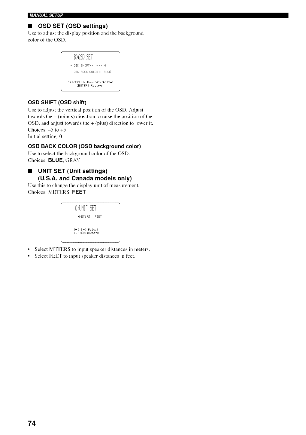
• OSD SET (OSD settings)
Use to adjust tile display position and the background
color of the OSD.
r_,¢=t ",, ==FT
,++..+,2+, 2+_+i
+ I]5D SHIFT ........ 0
OSD BAC); COLOR,,,BLIJE
[t3 [+1 :lJp "Do,4rl£_4] "[b] : 5e 1
[EmER =Return
OSD SHIFT (OSD shift)
Use to adjust the vertical position of the OSD. Adinst
tov+,ardsthe (minus) direction to raise the position of the
OSD, and adjust to'a, ards tile + (pills) direction to lower it.
Choices: -5 to +5
Initial setting: 0
OSD BACK COLOR (OSD background color)
Use to select tile backgrotmd color of tile OSD.
Choices: BLUE, GRAY
• UNIT SET (Unit settings)
(U.S.A. and Canada models only)
Use this to change tile display trait of measnrement.
Choices: METERS, FEET
¢l'q ILI? T +=FT
t,,,'W!+i 2,:i
H'IETER5 FEET
[.4]"[_]: Select
[ENTER : Relern
• Select METERS to input speaker distances in meters.
• Select FEET to input speaker distances in feet.
74
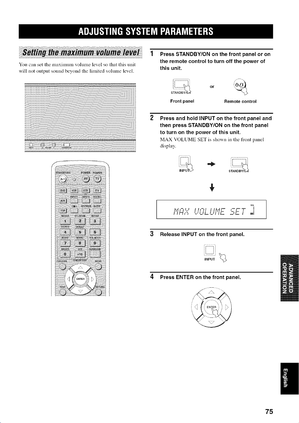
You can set the nmximum volmne level so that this unit
will not output sound beyond the limited volume level.
Press STANDBY/ON on the front panel or on
the remote control to turn off the power of
this unit.
s;_ or
Front panel Remotecontrol
Press and hold INPUT on the front panel and
then press STANDBY/ON on the front panel
to turn on the power of this unit.
MAX VOLUME SET is sho'a,n in tile front panel
display.
,!,
vet
f,H,:"-" '.'...'UL.Uf.:.'.,'.'-:.-'::: i ==
3 Release INPUT on the front panel.
Press ENTER on the front panel.
!
75
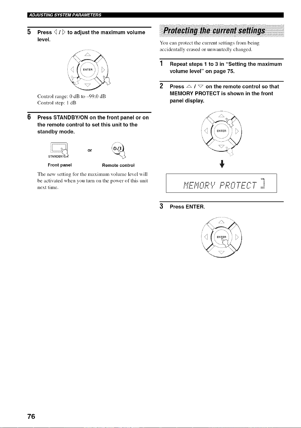
Press _ / _ to adjust the maximum volume
level.
Control range: 0 dB to -99.0 dB
Control step: 1dB
Press STANDBY/ON on the front panel or on
the remote control to set this unit to the
standby mode.
Frontpanel Remotecontrol
The new setting for the maxinmm volume level will
be activated when you trim on the power of this unit
next time.
You can protect the current settings from being
accidentally erased or nnwantedly changed.
1 Repeat steps 1 to 3 in "Setting the maximum
volume level" on page 75.
2 Press _ / _ on the remote control so that
MEMORY PROTECT is shown in the front
panel display.
VOL
.......................................... i
i:ii-" i:ii ii',:""r" i"'i',:'i i i i" i. i ::=
3 Press ENTER.
76
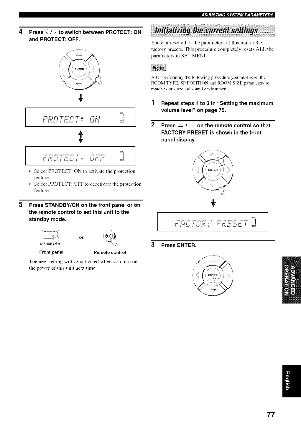
;[l)II_'.*ii/_+[PJk'j'_'_il:J_l'./__f:y__fj_/.,'ll::_,
Press _ / D to switch between PROTECT: ON
and PROTECT: OFF.
f\ "
+
rOE
PROT,,."5i27: O-',i ....
vok
P-";?O7L5(;7- Of.:f:: ....
• Select PROTECT: ON to activate the protection
feature.
• Select PROTECT: OFF to deactivate the protection
feature.
5 Press STANDBY/ON on the front panel or on
the remote control to set this unit to the
standby mode.
Front panel Remote control
The new setting will be activated when you turn on
the power of this unit next time.
You can reset all of the parameters of this unit to the
factory presets. This procedure completely resets ALL the
parameters in SET MENU.
After perlorming the following procedure you must reset the
ROOM TYPE, SP POSITION and ROOM SIZE parameters to
match yollr s/lrl+()lll/(] sound enviroi/nlei/t.
1 Repeat steps 1 to 3 in "Setting the maximum
volume level" on page 75.
2 Press _ / "<7 on the remote control so that
FACTORY PRESET is shown in the front
panel display.
/
VOL
t "+" ,'+', ,"*, "g" ,'% t "+'. t t _'+'. t "+'. t"+" ,'+" t"+" "_" :
i'- i.,,'.'i i i H.:.'",." i.-'i':.'i.- ".-.i.- i ==,i
3 Press ENTER.
/\ --
77
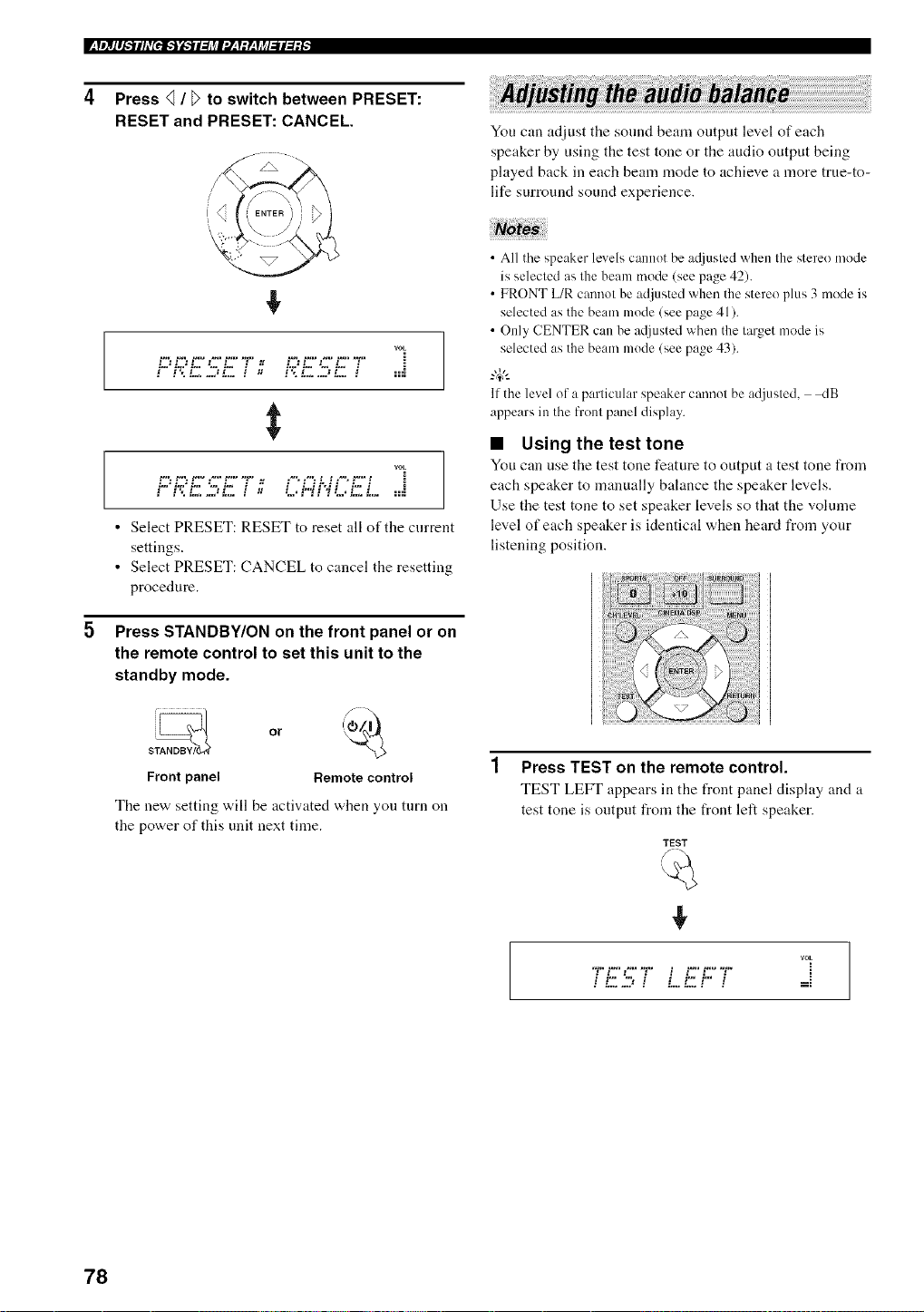
Press _ / _ to switch between PRESET:
RESET and PRESET: CANCEL.
+
rOE
i.-.'i.e'i.-. ".-..i.- , "J i.e'i.-. ".-.i.- ,
$
VOL
i..."i.e"i... "....i.- i "J i £.H"J I i... i
• Select PRESET: RESET to reset all of the current
settings.
• Select PRESET: CANCEL to cancel the resetting
procedure.
5 Press STANDBY/ON on the front panel or on
the remote control to set this unit to the
standby mode.
s_ or @._
Front panel Remote control
The new setting will be activated when you turn on
the power of this unit next time.
You can adjust the sonnd beam output level of each
speaker by using the test tone or the audio output being
played back in each bean] mode to achieve a more true-to-
life surround sound experience.
• All the speaker levels cannot be a_[justed when the stere() mode
is selected as the beam mode (see page 42).
• FRONT L/R cannot be adjusted whet] the stere() plus 3 mode is
selected as the beam mode (see page 41).
• Only CENTER cat] be a([justed whet] the target mode is
selected as the beam mode (see page 43).
-#:
If the level of a particular speaker cannot be adjusted, _:IB
appears it] the front panel display,
• Using the test tone
You can use the test tone feature to output a test tone from
each speaker to manually balance the speaker levels.
Use the test tone to set speaker levels so that the volume
level of each speaker is identical when heard from your
listening position.
Press TEST on the remote control.
TEST LEFT appears in the front panel display and a
test tone is output fro]]] the front left speaker.
TEST
+
rOE
*1...'.-. " ] t.-t.- "
E
78
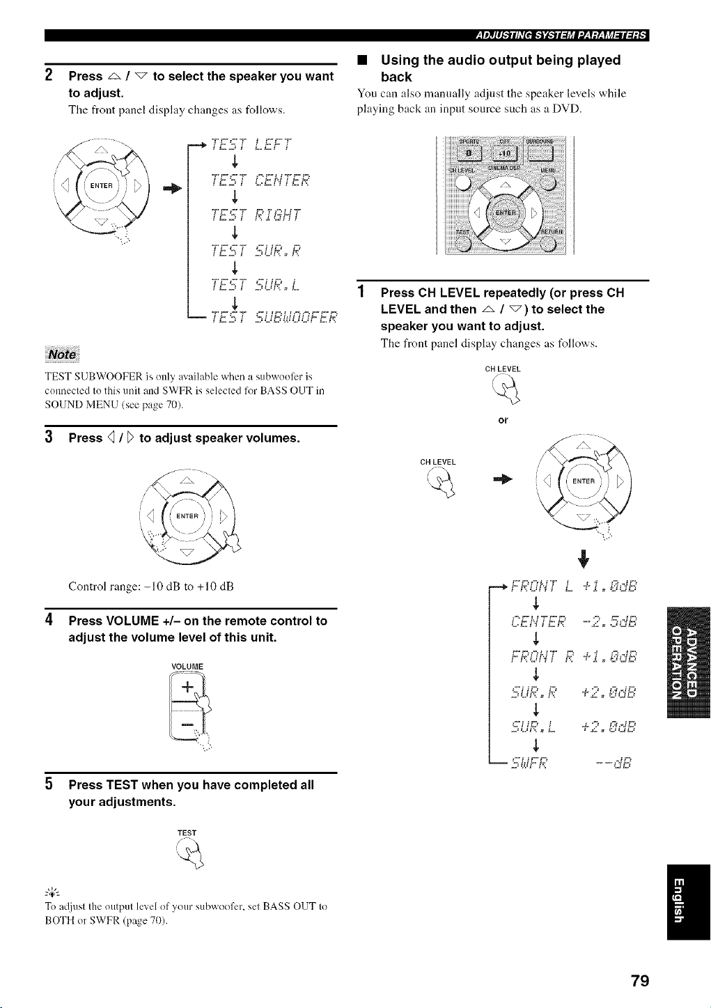
Press z_ / "_ to select the speaker you want
to adjust.
The front panel display changes as follows.
,=_
$
$
$
IL, L. i "*,. i H.2 L,2
$
i L "*,, i ".* i H.,2 i
i L=,J ! ,=,:L,:I'_ _ L
$
TEST SUBWOOFER is only available when a subwooli:r is
connected to this unit and SWFR is selected for BASS OUT in
SOUND MENU (see page 70).
3 Press 41/ T)to adjust speaker volumes.
/\ "
Control range: -10 dB to +10 dB
4 Press VOLUME +/- on the remote control to
adjust the volume level of this unit.
VOLUME
5 Press TEST when you have completed all
you r adjustments.
TEST
-&
To atljust the output level of your subwoofer, set BASS OUT to
BOTH or SWFR (page 70).
• Using the audio output being played
back
You can also manually adjust the speaker levels while
playing back :m input source such as a DVD.
Press CH LEVEL repeatedly (or press CH
LEVEL and then _ / _) to select the
speaker you want to adjust.
The front panel display changes as t_llows.
CH LEVEL
CH LEVEL
or
b h;Z.q'q;' L. "..".;'.., '..:::.'Gi::5
i "£ i',_ i £. L,2 "2 :" ,-*H*,J
k. k.q H'4 _ k.' ,4. '_ _4,",H.,4
$
...:L.H'_ _ i'_ : .g. = 5JLJLJ
$
L, i _L,2 i J. " 2 i,q ,-2 i*,.:
...:L.H'_ = L. : .g. _ :LJLJLJ
$
79
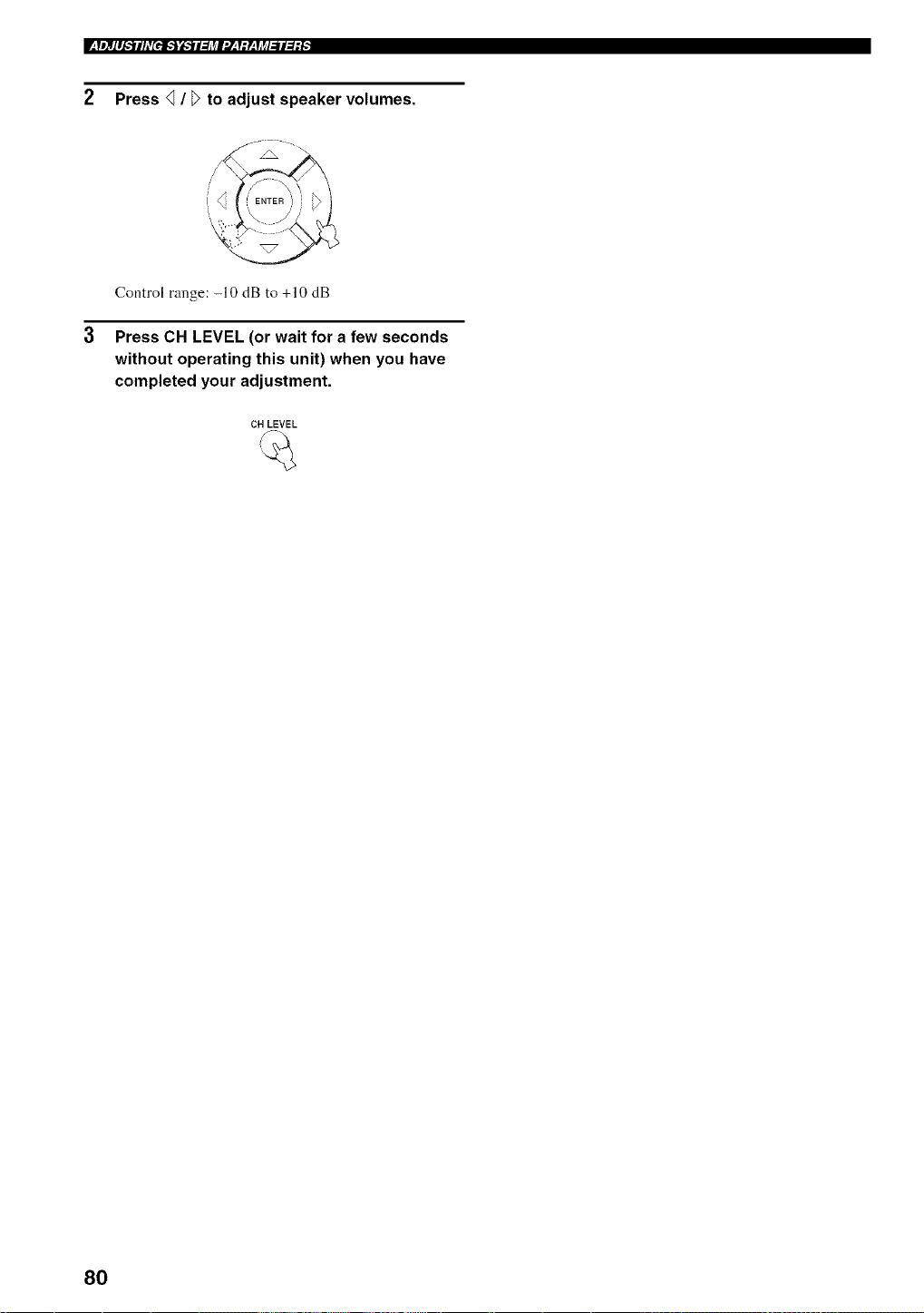
2 Press _ / _ to adjust speaker volumes.
/ J_ "
Control range: -10 dB to +10 dB
3 Press CH LEVEL (or wait for a few seconds
without operating this unit) when you have
completed your adjustment.
CH LEVEL
80
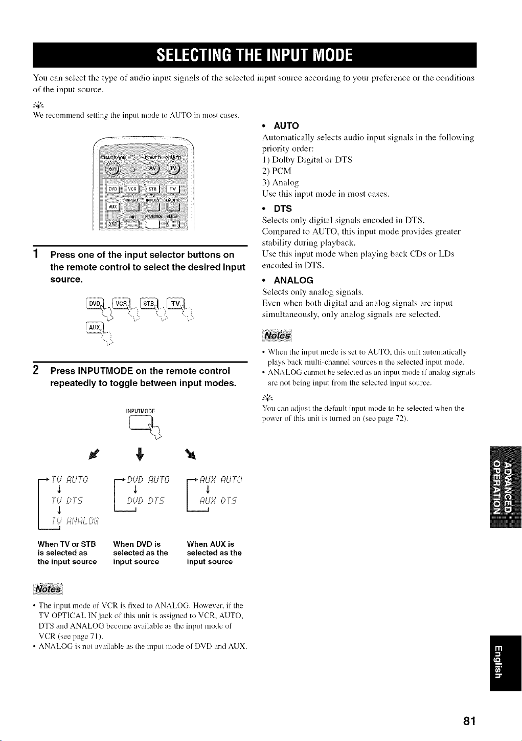
You can select the type of audio input signals of the selected input source according to your preference or the conditions
of the input source.
_%,._
We recommend selting the input mode Io AUTO in most cases.
f
!!!!!>!ill!ii
Press one of the input selector buttons on
the remote control to select the desired input
source.
"-:5.
Press INPUTMODE on the remote control
repeatedly to toggle between input modes.
INPUTMODE
• AUTO
Automatically selects andio input signals in the follovdng
priority order:
1) Dolby Digital or DTS
2) PCM
3) Analog
Use this input mode in most cases.
• DTS
Selects only digital signals encoded in DTS.
Compared to AUTO, this input mode provides greater
stability during playback.
Use this input mode when playing back CDs or LDs
encoded in DTS.
• ANALOG
Selects only analog signals.
Even when both digital and analog signals are input
simultaneously, only analog signals are selected.
• When the input mode is set to AUTO. this unit automatically
plays back multi-chamml sources n the selected input mode.
• ANALOG cannot be selected as an input mode if analog signals
are not being input from the selected input source.
You can adjust the default input mode to be selected when the
power of this trait is turned on (see page 72).
Lr_ ":iUTO ...... ":iUTQ _ ":iUTI3
T,'..,[:'T.!,7, _:: .,'.3T.'3 [: T.'3
!"_t;#,L,,::,G
When TV or STB When DVD is When AUX is
is selected as selected as the selected as the
the input source input source input source
• The input mode of VCR is fixed to ANALOG. However. if the
TV OPTICAL IN jack of this unit is assigned to VCR. AUTO.
DTS and ANALOG become m ailable as the input mode of
VCR (see page 71).
• ANALOG is not available as the input mode of DVD and AUX.
81
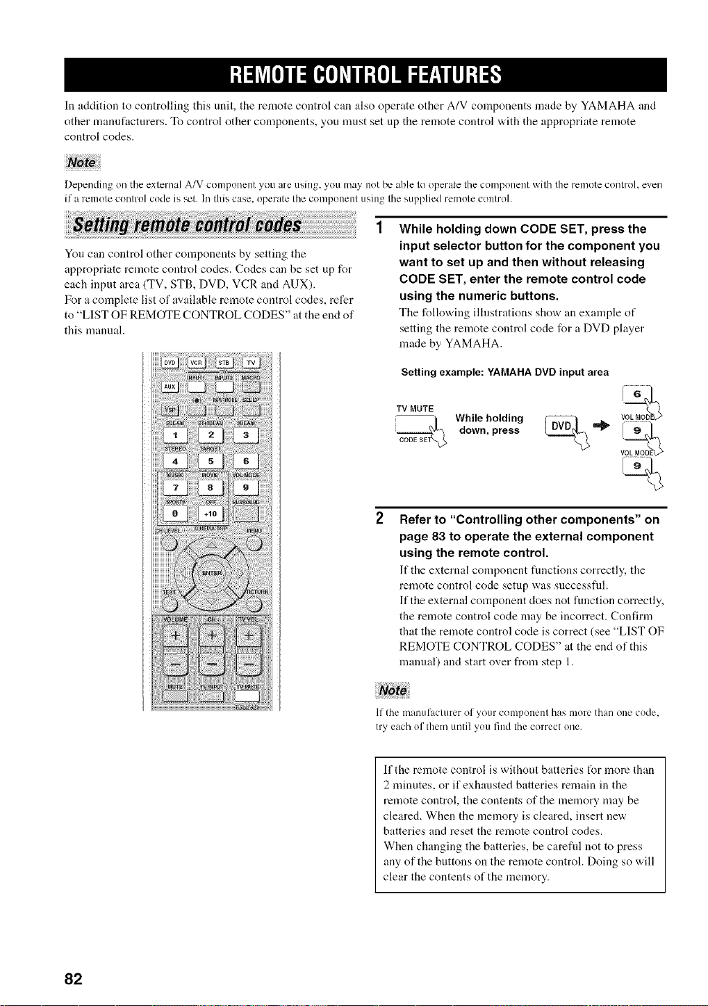
In addition to controlling this unit, the remote control can also operate other A/V components made by YAMAHA and
other manufacturers. To control other components, you must set up the remote control with the appropriate remote
control codes.
Depending on the exlemal A/V component you are using, you may not be able lo operale Ihe component wilh the remote control, even
if a remole conlrol code is set. In this case, operate the component using Ihe supplied remote conlrol.
You can control other components by setting the
appropriate remote control codes. Codes can be set up for
each input area (TV, STB, DVD, VCR and AUX).
For a complete list of available remote control codes, refer
to "LIST OF REMOTE CONTROL CODES" at the end of
this manual.
While holding down CODE SET, press the
input selector button for the component you
want to set up and then without releasing
CODE SET, enter the remote control code
using the numeric buttons.
The following illustrations show an example of
setting the remote control code for a DVD player
made by YAMAHA.
Setting example: YAMAHA DVD input area
TV MUTE voL6M_OD
WhilwenPpIldi$$ _ =_ !_
Refer to "Controlling other components" on
page 83 to operate the external component
using the remote control.
If the external component functions correctly, the
remote control code setup was successfld.
If the external component does not function correctly,
the remote control code may be incorrect. Confirm
that the remote control code is correct (see "LIST OF
REMOTE CONTROL CODES" at the end of this
manual) and start over from step 1.
If the rnan[IfaCltll'er o[-your conlponenl has nlore than one code.
try each ol them until yon find the correct one.
If the remote control is without batteries t_r more than
2 nfinutes, or if exhausted batteries remain in the
remote control, the contents of the memory may be
cleared. When the memory is cleared, insert new
batteries and reset the remote control codes.
When changing the batteries, be careful not to press
any of the buttons on the remote control. Doing so will
clear the contents of the memory.
82
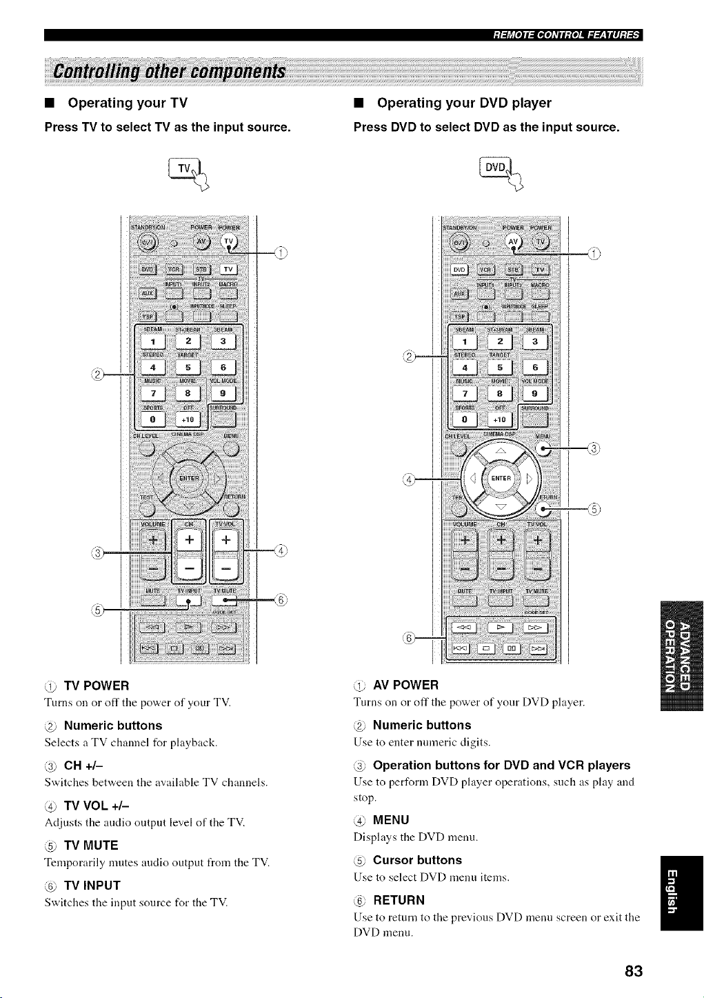
• Operating your TV
Press TV to select TV as the input source.
• Operating your DVD player
Press DVD to select DVD as the input source.
d) TV POWER
Turns on or oft"tile pov,,er of your TV.
@ Numeric buttons
Selects a TV channel for playback.
@ CH +/-
Switches betw,een tile available TV channels.
@ TV VOL +/-
Adjusts the audio output level of the TV.
@ TV MUTE
Temporarily mutes audio output from the TV.
@ TV INPUT
Switches the input source for the TV.
@ AV POWER
Turns on or off the power of your DVD player.
@ Numeric buttons
Use to enter numeric digits.
@ Operation buttons for DVD and VCR players
Use to perl\_rm DVD phtyer operations, such as phty and
stop.
@ MENU
Displays the DVD menu.
@ Cursor buttons
Use to select DVD menu items.
@ RETURN
Use to return to the previous DVD menu screen or exit the
DVD menu.
I
83
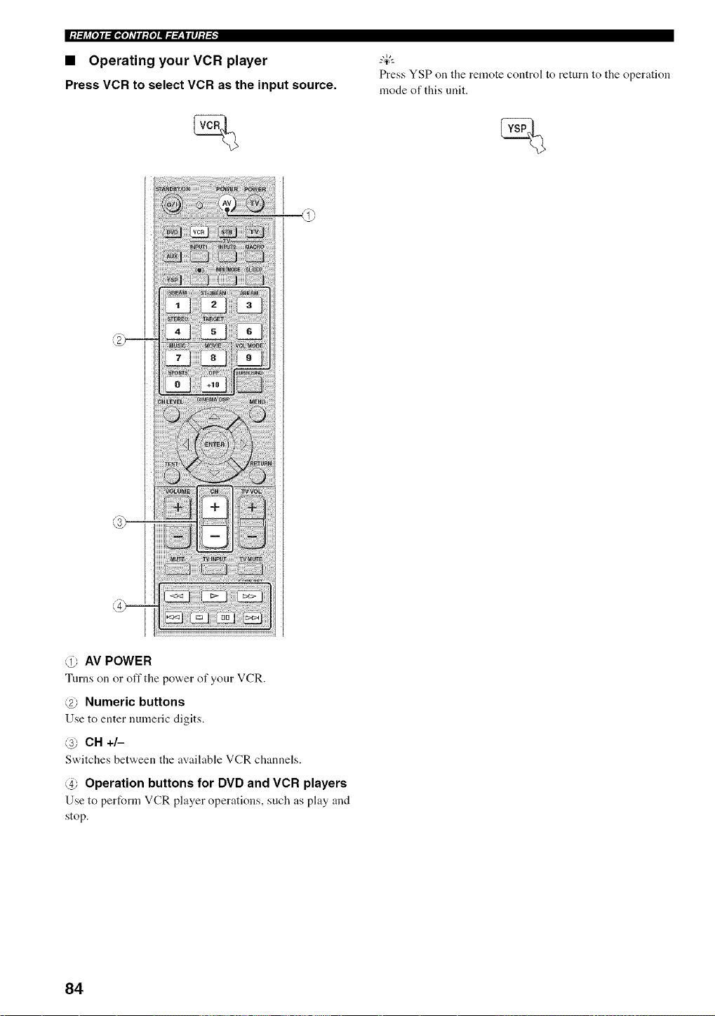
|:/.._j_[O]I_[I,[O]_TII:{O]I_._.___|II]:/-'_"
• Operating your VCR player
Press VCR to select VCR as the input source.
Press YSP on the remote control to return to the operation
mode of this unit.
@ AV POWER
Turns on or off the power of your VCR.
@ Numeric buttons
Use to enter numeric digits.
@ CH +/-
Switches bet'a,een the available VCR channels.
@ Operation buttons for DVD and VCR players
Use to perform VCR player operations, such as play and
stop.
84
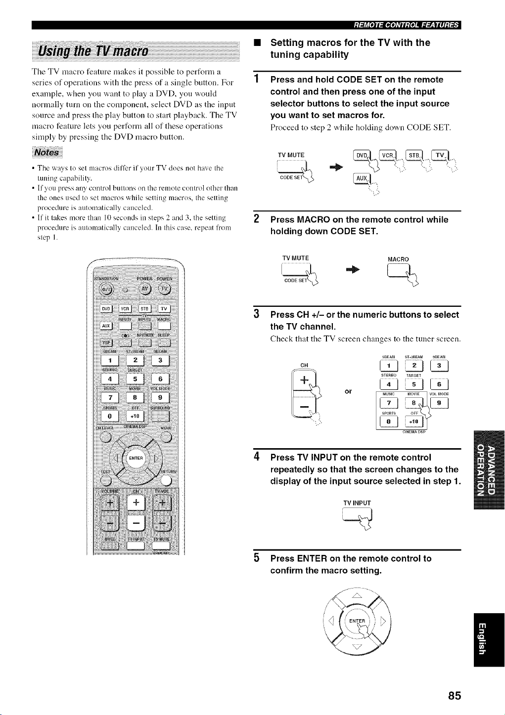
The TV macro feature makes it possible to pertUrm a
series of operations with the press of a single button. For
example, when you want to play a DVD, you would
normally turn on the component, select DVD as the input
source and press the play button to start playback. The TV
macro feature lets you perform all of these operations
simply by pressing the DVD macro button.
• The ways to set macrus dilfcr if yuur TV does nut have the
tuning capability.
• If you press any control butt(ms oil the remote control other than
the ones used tu set macros while setting macrus, the setting
procedure is automatically canceled.
• If it takes more than 10 seconds in steps 2 and 3. the setting
procedure is automatically canceled. In this case. repeat l?om
step I.
:l:lj_[o]lll[_rol_Til:Io111lT:r__|llJM:_
Setting macros for the TV with the
tuning capability
Press and hold CODE SET on the remote
control and then press one of the input
selector buttons to select the input source
you want to set macros for.
Proceed to step 2 while holding down CODE SET.
,vo0,
i
Press MACRO on the remote control while
holding down CODE SET.
TV MUTE MACRO
Press CH +/- or the numeric buttons to select
the TV channel.
Check that the TV screen changes to tile tuner screen.
CH
or
5BEAM ST*aB_A_ _BEAM
STEREO TARGET
MUSIC MOWE VOL MODE
__SPORTS OFF
CINEMADSP
Press TV INPUT on the remote control
repeatedly so that the screen changes to the
display of the input source selected in step 1.
TV iNPUT
Press ENTER on the remote control to
confirm the macro setting.
85
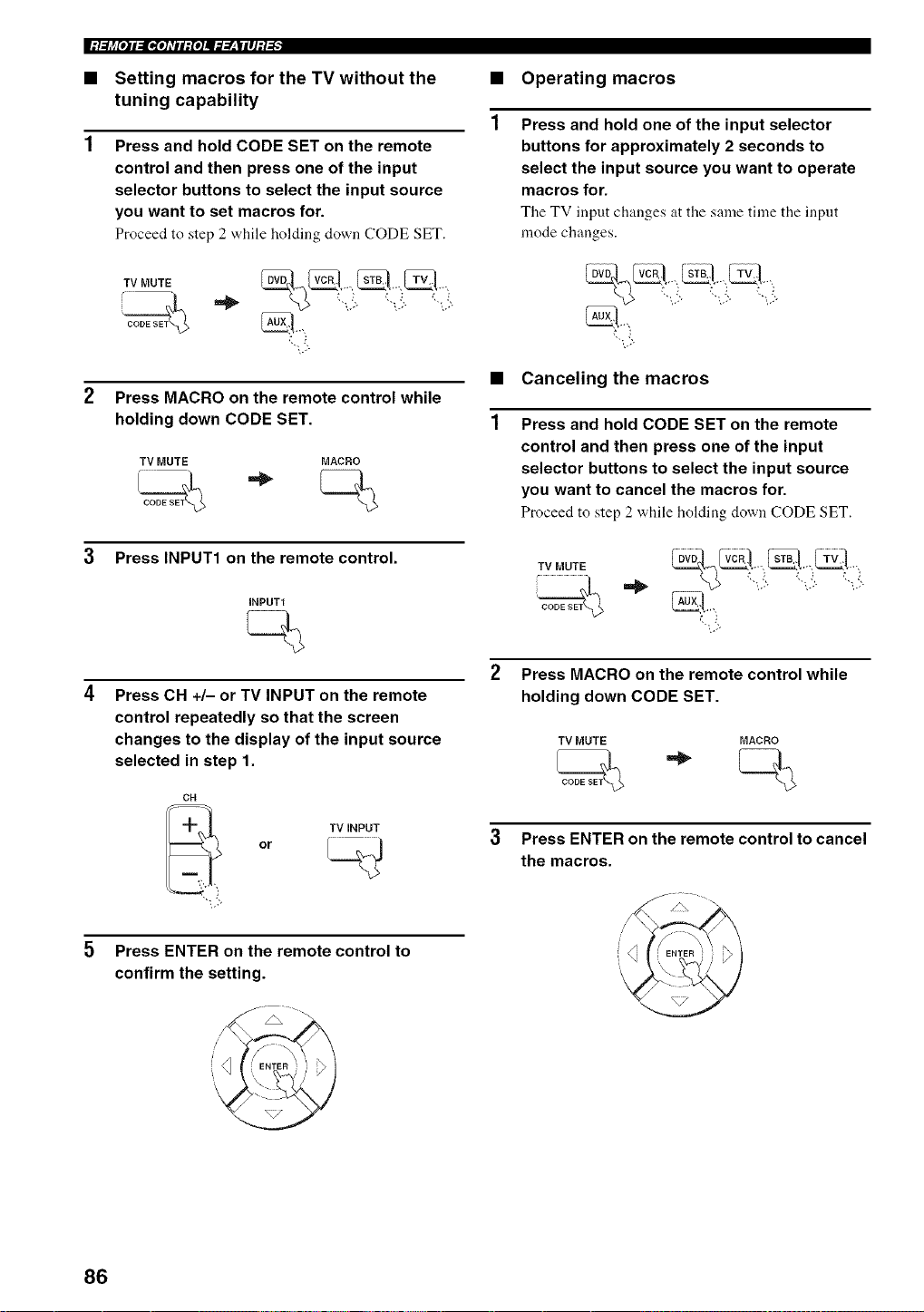
I:/.._j_[O]I_[I,[O]_TII:{O]I_._.___III]:/-'_"
• Setting macros for the TV without the
tuning capability
Press and hold CODE SET on the remote
control and then press one of the input
selector buttons to select the input source
you want to set macros for.
Proceed to step 2 while holding down (.'ODE SET.
2 Press MACRO on the remote control while
holding down CODE SET.
TV MUTE MACRO
3 Press INPUT1 on the remote control.
INPUT1
Press CH +/- or TV INPUT on the remote
control repeatedly so that the screen
changes to the display of the input source
selected in step 1.
CH
TV INPUT
or
Press ENTER on the remote control to
confirm the setting.
• Operating macros
Press and hold one of the input selector
buttons for approximately 2 seconds to
select the input source you want to operate
macros for.
The TV input changes at the same time the input
mode changes.
",.:
• Canceling the macros
Press and hold CODE SET on the remote
control and then press one of the input
selector buttons to select the input source
you want to cancel the macros for.
Proceed to step 2 "a.hileholding down CODE SET.
2 Press MACRO on the remote control while
holding down CODE SET.
TV MUTE MACRO
3 Press ENTER on the remote control to cancel
the macros.
_NTER '} } i
86
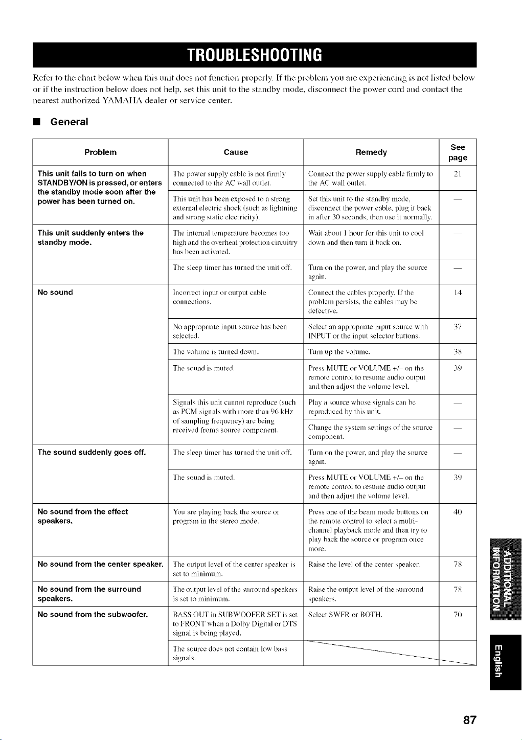
Refer to the chart below when this unit does not function properly. If the problem you are experiencing is not listed below
or if the instruction below does not help, set this unit to the standby mode, disconnect the power cord and contact the
nearest authorized YAMAHA dealer or service center.
• General
This unit fails to turn on when
STANDBY/ON is pressed, or enters
the standby mode soon after the
power has been turned on.
See
Problem Cause Remedy
page
21
This unit suddenly enters the
standby mode.
No sound
The sound suddenly goes_f.
The power supply cable is not firmly
connected to the AC wall outlet.
This unit has been exposed to a strong
external electric shock (such as lighming
and strong static electricity).
Tile internal temperature becomes too
high and the overheat protection circuitry
has been activated.
The sleep timer has turned the unit off.
Incorrect input or output cable
connection s.
Connect the power supply cable firmly to
the AC wall outlet.
Set this unit to the standby mode,
disconnect the power cable, plug it back
in after 3(}seconds, then use it normally.
Wait about 1 hour for this unit to cool
down and then mrn it back on.
Turn on the power, and play the source
again.
Connect the cables properly. If the 14
problem persists, the cables may be
deli:ctive.
No appropriate input source has been Select an appropriate input source with 37
selected. INPUT or the input selector buttons.
The volume is turned down. Turn up the volume. 38
The sound is muted. Press MUTE or VOLUME +_ on the 39
remote control to resume audio otltpllt
and then a(!just the volume level.
Play a source whose signals call be
reproduced by this unit.
Change the system settings of the source
COlllponent.
Turn on the power, and play the source
again.
Press MUTE or VOLUME +_ on Ihe 39
remote control to rcs/ime audio otltpllt
and then a({just the volume level.
Press one of the beam mode buttons on 40
the remote control to select a multi-
channel playback mode and then try to
play back the source or program once
more.
Signals this unit cannot reproduce (such
as PCM signals with more than 96 kHz
of sampling frequency) are being
received frollla source component.
The sleep timer has turned the unit off.
The sound is muted.
No sound from the effect You are playing back the source or
speakers, program in the stereo mode.
No sound from the center speaker. The output level of the center speaker is Raise the level of the center speaker. 78
set to minin/tlllL
No sound from the surround The output level of the surround speakers Raise the output level of the surround 78
speakers, is set to minimum, speakers.
No sound from the subwoofer. Select SWFR or BOTH. 70BASS OUT in SUBWOOFER SET is set
to FRONT when a Dolby Digital or DTS
signal is being played.
The source does not contain low bass
signals.
87
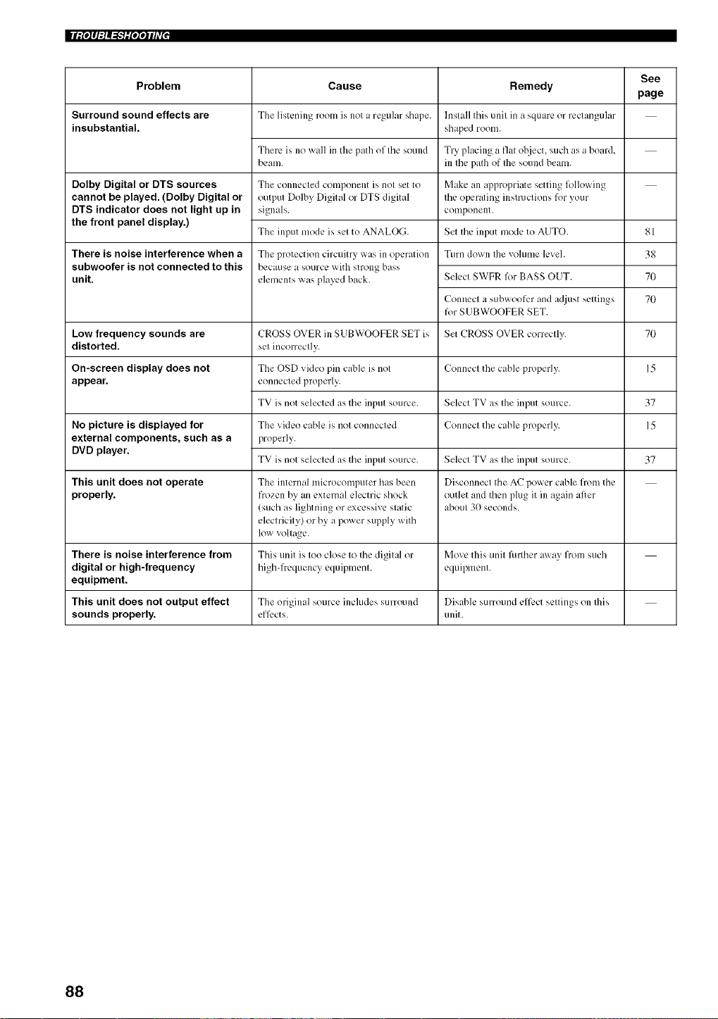
IIIitolll:lAI-T'lil'l'l*lflVl,
Cause Remedy
The listening roonl is not a regular shape.
Problem
Surround sound effects are
insubstantial.
Dolby Digital or DTS sources
cannot be played. (Dolby Digital or
DTS indicator does not light up in
the front panel display.)
There is noise interference when a
subwoofer is not connected to this
unit.
There ix no wall in the path of tile sound
beam.
The connected component ix not set to
output Dolby Digital or DTS digital
signals.
The input mode ix set to ANALOG.
The protection circuitry was in operation
because a source with strong bass
elements was played back.
Install this unit in a square or rectangular
shaped room.
Try placing a fiat object, such as a board,
ill the path of flae sound beam.
Make an appropriate setting Rdlowing
the operating instructions for your
component.
Set the input mode to AUTO.
Turn down the volume level.
Select SWFR R_rBASS OUT.
Connect a subwoofcr and adjust settings
for SUBWOOFER SET.
CROSS OVER in SUBWOOFER SET ix
set incorrectly.
The OSD video pin cable ix not
connected properly.
TV ixnot selected as the input source.
See
page
81
38
70
70
Low frequency sounds are Set CROSS OVER correctly. 70
distorted.
Connect the cable properly. 15
The video cable is not connected
properly.
TV ixnot selected as the input source.
Select TV as the input source.
Connect the cable properly.
On-screen display does not
appear.
No picture is displayed for
external components, such as a
DVD player.
37
15
Select TV as the input source. 37
This unit does not operate The internal microcomputer has been Disconnect the AC power cable from the
properly, frozen by an external electric shock outlet and then plug it ill again after
(such as lightning or excessive static about 30 seconds.
electricity) or by a power supply with
low voltage.
There is noise interference from This trait ixtoo close to the digital or Move this trait further away from such
digital or high-frequency high-frequency equipment, equipment.
equipment.
This unit does not output effect The original source includes surround Disabk, surround ,_,ff,_,ctsettings on tiffs
sounds properly, efl__,cts, unit.
88
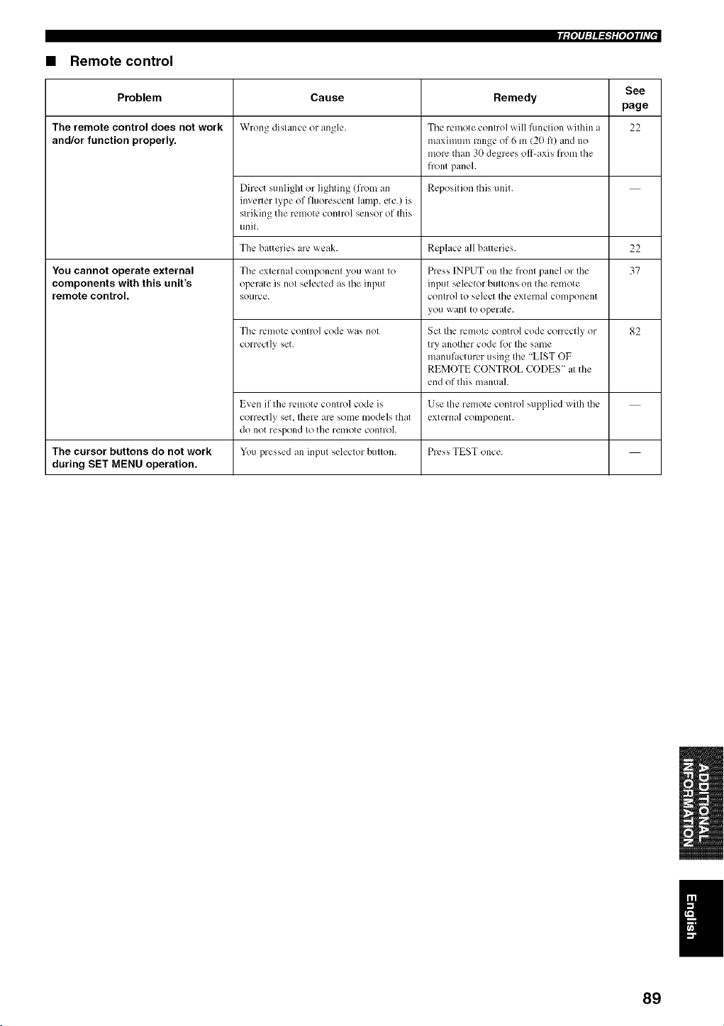
rf(°_q:l_=h_iNqih7 J
• Remote control
See
Cause Remedy
page
Wrong distance or angle. 22
Problem
The remote control does not work
and/or function properly.
You cannot operate external
components with this unit's
remote control.
The remote control will function within a
maximum range of 6 m (20 fl) and no
more than 30 degrees oil-axis from the
front panel.
Dirc.ctsunlight or lighting (from an Reposition this unit.
inverter type of fluorescent lamp, etc.) is
striking the remote control sensor of this
unit.
The batteries arc.weak. Replace all batteries. 22
37
The external component you want to
operate is not selected as tile input
source.
Tile remote control code was not
correctly set.
Even if the remote control code is
correctly set, Ibere arc, some models that
do not respond to the remote control.
You pressed an input selector button.
Press INPUT on the front panel or the
input selector buttons on the remote
control to select the external component
yotl want to operate.
Set the remote control code correctly or
try another code for the same
manufacturer using the "LIST OF
REMOTE CONTROL CODES" at the
end of this manual.
Use the remote control supplied with tile
external component.
82
The cursor buttons do not work Press TEST once.
during SET MENU operation.
89
• Dolby Digital
Dolby Digital is a digital surround sound system that gives
you completely independent multi-channel audio. With 3
front channels Cleft, center, and right), and 2 surronnd
stereo channels, Dolby Digital provides 5 full-range audio
channels. With an additional channel especially for bass
effects, called LFE (low frequency effect), the system has
a total of 5.1-channels (LFE is counted as 0.1 channel). By
using 2-channel stereo for the surround speakers, more
accurate moving sound effects and surround sound
environment are possible than with Dolby Surround. The
wide dynamic range (from maximunl to minimmn
volume) reproduced by the 5 fnll-range channels and the
precise sound orientation generated using digital sound
processing provide listeners with previously nnheard of
excitement and realism.
With this unit, any sound environment from monaural up
to a 5. l-channel configuration can be freely selected for
your enjoyment.
• Dolby Pro Logic II
Dolby Pro Logic II is an improved technique used to
decode vast nnmbers of existing Dolby Surround software.
This new technology enables a discrete 5-channel
playback with 2 front left and right channels, 1 center
channel, and 2 surround left and right channels (instead of
only 1 surround channel for conventional Pro Logic
technology). Music and Game modes are also available for
2-channel sources in addition to the Movie mode.
• Dolby Surround
Dolby Surround uses a 4 channel analog recording system
to reproduce realistic and dynanfic sound effects: 2 front
left and right channels (stereo), a center channel t_r dialog
0nonanral), and a surround channel for special sound
effects (monaural). The surround channel reproduces
sound within a narrow t_equency range.
Dolby Surround is widely used with nearly all video tapes
and laser discs, and in many TV and cable broadcasts as
well. The Dolby Pro Logic decoder built into this unit
employs a digital signal processing system that
automatically stabilizes the volnme on each channel to
enhance moving sound effects and directionality.
• DTS (Digital Theater Systems)
Digital Surround
DTS digital surround "a,as developed to rephtce tire analog
soundtracks of movies with a 6-channel digital sound
track, and is now rapidly gaining popularity in movie
theaters around the world. Digital Theater Systems Inc.
has developed a home theater system so that you can enjoy
the depth of sound and natural spatial representation of
DTS digital surround in your home. This system prodnces
practically distortion-free 6-channel sound (technically, a
left, right and center channels, 2 surround channels, plus
an LFE 0.1 channel as a subwoofer, for a total of 5. l-
channels). The unit incorporates a DTS-ES decoder that
enables 6.1- channel reprodnction by adding the surround
back channel to existing 5. l-channel format.
• Neo:6
Neo:6 decodes tire conventional 2-channel sources for 6
channel playback by the specific decoder. It enables
playback with the full-range channels with higher
separation just like digital discrete signal playback. Two
modes are available; Music mode for playing music
sources and Cinema mode for movies.
• PCM (Linear PCM)
Linear PCM is a signal t_rmat under which an analog
audio signal is digitized, recorded and transnfitted without
using any compression. This is used as a method of
recording CDs and DVD audio. The PCM system uses a
technique for sampling the size of the analog signal per
very small unit of time. Standing for pulse code
modulation, the analog signal is encoded as pulses and
then modulated for recording.
• LFE 0.1 channel
This channel is for the reproduction of low bass signals.
The t?equency range for this channel is 20 Hz to 120 Hz.
This channel is counted as 0.1 because it only enforces a
low frequency range compared to the fnll-r:mge
reproduced by the other 5/6 channels in Dolby Digital or
DTS 5.1/6. l-channel systems.
90
Audio Pin Cable ..................................................... 15 to 18 On-screen display (OSD) ................................................ 24
OSD video pill cable ....................................................... 15
Optical cable ....................................................... 15, 18, 19
Beam modes .................................................................... 40
Coaxial digital output.jack ................................................ 8
Coaxial digital input .jack .................................................. 8
PCM ................................................................................ 81
Power cable ..................................................................... 21
Digital Audio Pin Cable .................................................. 16
Display ........................................................................ 7, 24
Dolby Digital .................................................................. 44
Dolby Pro Logic .............................................................. 44
Dolby Pro Logic II .......................................................... 44
DTS ................................................................................. 44
Dynamic range ................................................................ 71
Remote control ............................................................ 9, 22
Remote control code ....................................................... 82
Surround mode ................................................................ 44
Sleep timer ...................................................................... 55
SET MENU ..................................................................... 24
Test tone .......................................................................... 78
BASIC SETUP ............................................................... 57
LFE 0.1 channel ........................................................ 70, 90
MANUAL SETUP .......................................................... 63
MEMORY ................................................................. 34, 35
Night listening modes ..................................................... 52
91
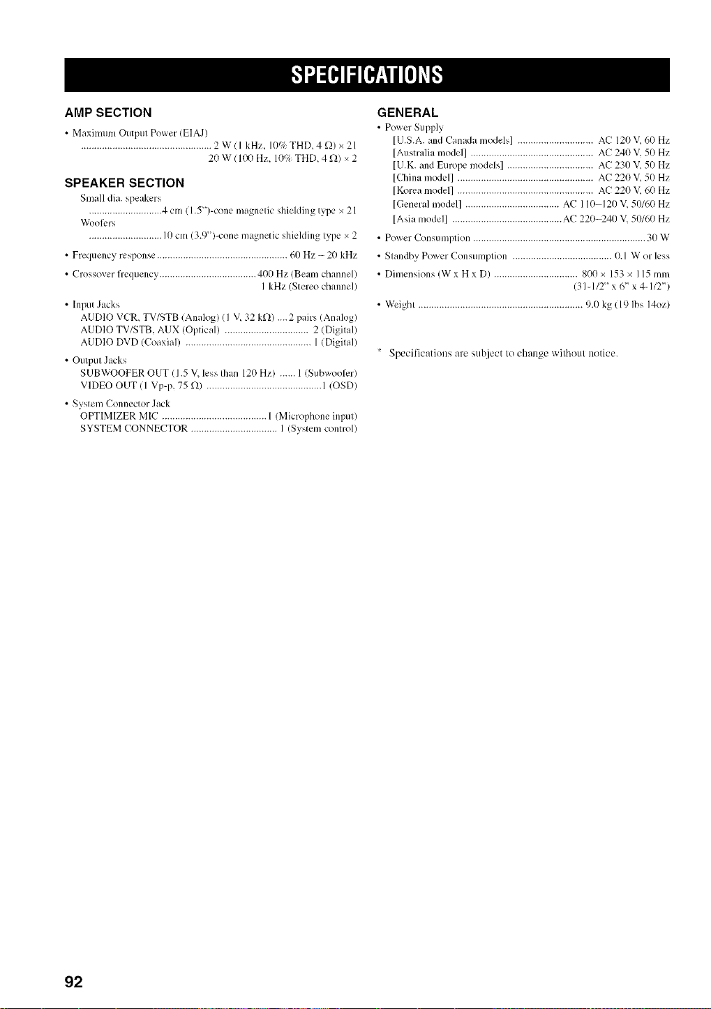
AMP SECTION
• Maximum Output Power (EIAJ)
.................................................. 2W(I kHz, 10c/_ THD, 4 _2)x21
20 W ( 100 Hz, 109; THD, 4 _)_)x 2
SPEAKER SECTION
Small dia. speakers
............................ 4 cm ( 1.5 ")-cone magnetic shielding type x 21
W'ool__.rs
............................ I 0 cm (3.9")-cone magnetic shielding type × 2
• Frequency response .................................................. 60 Hz - 20 kHz
• Crossover fiequency ..................................... 400 Hz (Beam channel)
I kHz (Stereo channel)
• Input Jacks
AUDIO VCR, TV/STB (Analog) (I V, 32 k_)_) ....2 pairs (Analog)
AUDIO TV/STB, AUX (Optical) ................................ 2 (Digital)
AUDIO DVD (Coaxial) ................................................ 1 (Digital)
• Output Jacks
S UBWOOFER OUT (1.5 V, less Ihan 120 Hz) ...... I (SubwoolL.r)
VIDEO OUT ( 1 Vp-p, 75 _) ............................................ 1 IOSD)
• System Connector Jack
OPTIMIZER MIC ............................................................
SYSTEM CONNECTOR ................................. I (System control)
GENERAL
• Power Supply
[U.S.A. and Canada models] ............................. AC 120 V, 60 Hz
[Australia model] ............................................... AC 240 V, 50 Hz
[U.K. and Europe models] ................................. AC 230 V, 50 Hz
[China model] .................................................... AC 220 V, 50 Hz
[Korea model] .................................................... AC 220 V, 60 Hz
[General model] .................................... AC 110-120 V, 50/60 Hz
[Asia model] .......................................... AC 220-240 V, 50/60 Hz
• Power Consumption .................................................................. 30 W
• Standby Power Consumption ...................................... 0.1 W or less
• Dimensions (W x H x D) ................................ 800 x 153 x 115 mm
(31-1/2" x 6 _ x 4-1/2")
• Weight ............................................................... 9.0 kg ( 19 Ibs 14oz)
Specifications are subject to change without notice.
92
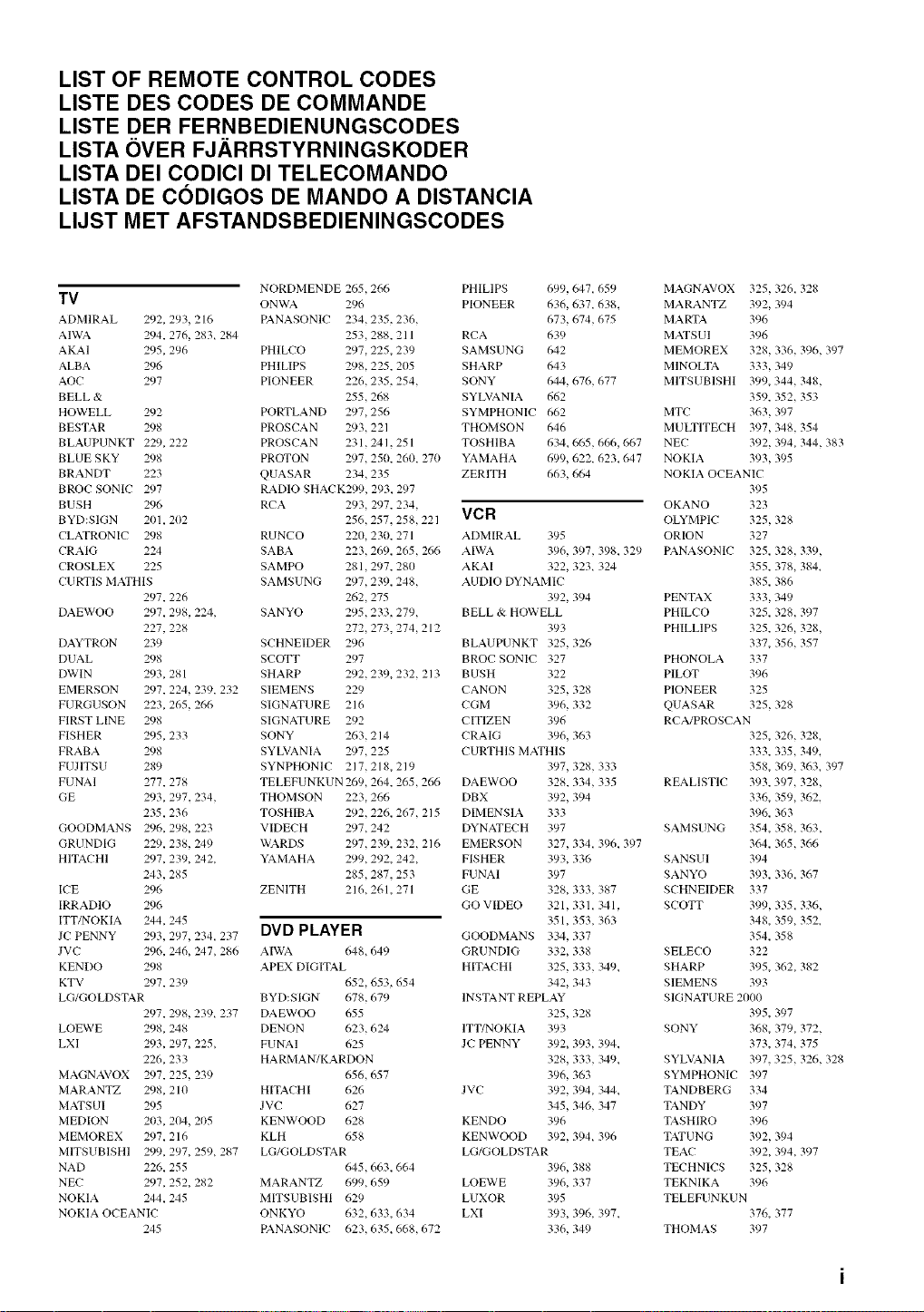
LIST OF REMOTE CONTROL CODES
LISTE DES CODES DE COMMANDE
LISTE DER FERNBEDIENUNGSCODES
LISTA OVER FJ.ARRSTYRNINGSKODER
LISTA DEI CODICI DI TELECOMANDO
LISTA DE CODIGOS DE MANDO A DISTANCIA
LIJST MET AFSTANDSBEDIENINGSCODES
NORDMENDE 265,266
TV ONWA 296
ADMIRAL 292, 293, 216 PANASONIC 234,235, 236,
AIWA 294, 276, 283+ 284 253,288, 211
AKAI 295, 296 PHILCO 297,225, 239
ALBA 296 PHILIPS 298,225, 205
AOC 297 PIONEER 226,235, 254,
BELL & 255,268
HOWELL 292 PORTLAND 297,256
BESTAR 298 PROSCAN 293,221
BLAUPUNKT 229, 222 PROSCAN 231,241, 251
BLUE SKY 298 PROTON 297,250, 260, 270
BRANDT 223 QUASAR 234,235
BROC SONIC 297 RADIO SHACK299, 293, 297
BUSH 296 RCA 293, 297, 234,
BYD:SIGN 201,202 256,257, 258,221
CLATRONIC 298 RUNCO 220, 230, 271
CRAIG 224 SABA 223,269, 265,266
CROSLEX 225 SAMPO 281,297, 280
CURTIS MATHIS SAMSUNG 297,239, 248,
297, 226 262,275
DAEWOO 297, 298, 224, SANYO 295,233, 279,
227, 228 272,273, 274,212
DAYTRON 239 SCHNEIDER 296
DUAL 298 SCOTT 297
DWIN 293, 281 SHARP 292,239+ 232, 213
EMERSON 297, 224, 239, 232 SIEMENS 229
FURGUSON 223, 265,266 SIGNATURE 216
FIRST LINE 298 SIGNATURE 292
FISHER 295, 233 SONY 263,214
FRABA 298 SYLVANIA 297,225
FUJITSU 289 SYNPHONIC 217,218,219
FUNAI 277, 278 TELEFUNKUN 269,264, 265,266
GE 293, 297, 234, THOMSON 223,266
235,236 TOSHIBA 292,226, 267, 215
GOODMANS 296, 298, 223 VIDECH 297,242
GRUNDIG 229, 238, 249 WARDS 297,239, 232, 216
HITACHI 297, 239, 242, YAMAHA 299,292, 242,
243, 285 285,287, 253
ICE 296 ZENITH 216,261,271
IRRADIO 296
ITT/NOKIA 244, 245
JC PENNY 293, 297, 234, 237 DVD PLAYER
JVC 296, 246, 247, 28(, AIWA (,48,649
KENDO 298 APEX DIGITAL
KTV 297, 239 652,653, 654
LG/GOLDSTAR BYD:SIGN 678,679
297, 298,239+ 237 DAEWOO 655
LOEWE 298, 248 DENON 623,624
LXI 293, 297, 225, FUNAI 625
226, 233 HARMAN7KARDON
MAGNAVOX 297, 225,239 656,657
MARANTZ 298, 210 HITACHI 626
MATSUI 295 JVC 627
MEDION 203, 204, 205 KENWOOD 628
MEMOREX 297, 216 KLH 658
MITSUBISHI 299, 297, 259+ 287 LG/GOLDSTAR
NAD 226, 255 645,663,664
NEC 297, 252, 282 MARANTZ 699,659
NOKIA 244, 245 MITSUBISHI 629
NOKIA OCEANIC ONKYO 632,633, 634
245 PANASONIC 623,635+ 668,672
PHILIPS 699,647, 659
PIONEER 636,637, 638,
673,674,675
RCA 639
SAMSUNG 642
SHARP 643
SONY 644,676,677
SYLVANIA 662
SYMPHONIC 662
THOMSON 646
TOSHIBA 634,665,666,667
YAMAHA 699,622, 623+ 647
ZERlTH 663,664
VCR
ADMIRAL 395
AIWA 396, 397,398, 329
AKAI 322, 323+ 324
AUDIO DYNAMIC
392, 394
BELL & HOWELL
393
BLAUPUNKT 325,326
BROC SONIC 327
BUSH 322
CANON 325,328
CGM 396, 332
CITIZEN 396
CRAIG 396, 363
CURTHIS MATHIS
397, 328,333
DAEWOO 328, 334,335
DBX 392, 394
DIMENSIA 333
DYNATECH 397
EMERSON 327, 334, 396, 397
FISHER 393, 336
FUNAI 397
GE 328, 333,387
GO Vff)EO 321,331,341,
351,353,363
GOODMANS 334, 337
GRUNDIG 332, 338
HITACHI 325,333,349,
342, 343
INSTANT REPLAY
325,328
ITT/NOKIA 393
JC PENNY 392, 393, 394,
328, 333,349+
396, 363
JVC 392, 394, 344,
345,346, 347
KENDO 396
KENWOOD 392, 394+ 396
LG/GOLDSTAR
396, 388
LOEWE 396, 337
LUXOR 395
LXI 393, 396, 397,
336, 349
MAGNAVOX 325,326, 328
MARANTZ 392, 394
MARTA 396
MATSUI 396
MEMOREX 328,336, 396, 397
MINOLTA 333,349
MITSUBISHI 399, 344, 348,
359, 352, 353
MTC 363,397
MULTITECH 397,348, 354
NEC 392, 394, 344,383
NOKIA 393,395
NOKIA OCEANIC
395
OKANO 323
OLYMPIC 325,328
ORION 327
PANASONIC 325, 328, 339,
355, 378, 384+
385, 386
PENTAX 333,349
PHILCO 325, 328, 397
PHILLIPS 325, 326, 328,
337, 356, 357
PHONOLA 337
PILOT 396
PIONEER 325
QUASAR 325,328
RCA/PROSCAN
325, 326, 328,
333, 335,349,
358, 369, 363, 397
REALISTIC 393, 397, 328,
336, 359, 362,
396, 363
SAMSUNG 354, 358, 363,
364, 365,366
SANSUI 394
SANYO 393, 336, 367
SCHNEIDER 337
SCOTT 399, 335,336,
348, 359, 352,
354, 358
SELECO 322
SHARP 395, 362, 382
SIEMENS 393
SIGNATURE 2000
395, 397
SONY 368, 379, 372,
373, 374, 375
SYLVANIA 397, 325, 326, 328
SYMPHONIC 397
TANDBERG 334
TARDY 397
TASHIRO 396
TATU NG 392, 394
TEAC 392, 394, 397
TECHNICS 325,328
TEKNIKA 396
TELEFUNKUN
376, 377
THOMAS 397
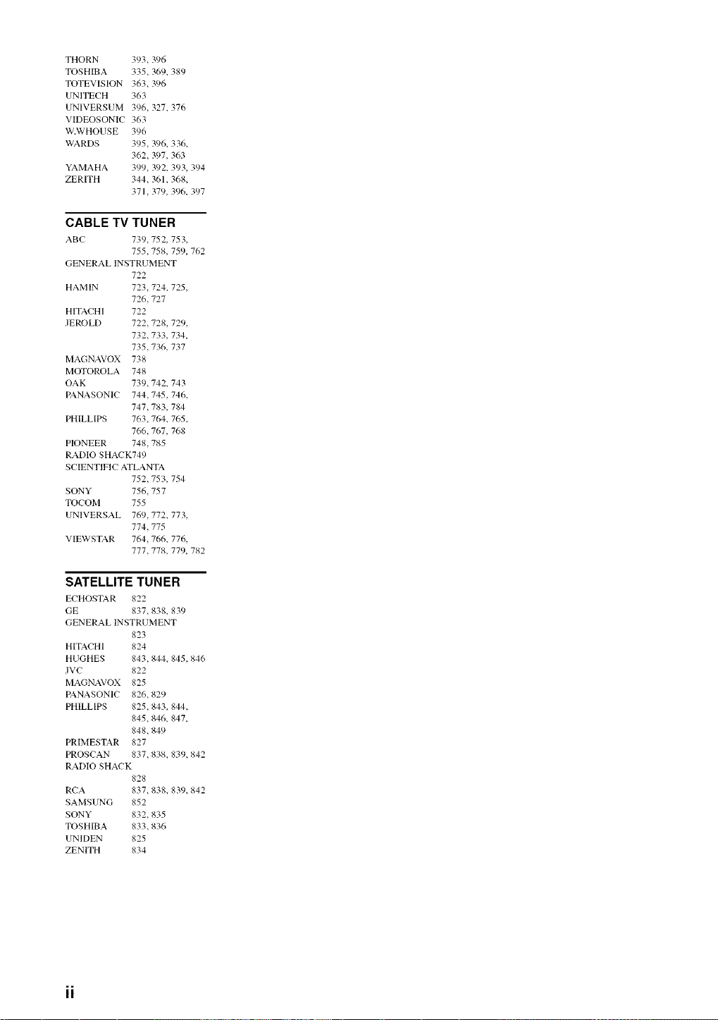
THORN 393,396
TOSHIBA335,369,389
TOTEVISION363,396
UNITECH363
UNIVERSUM396,327,376
VIDEOSONIC363
W.WHOUSE396
WARDS 395,396.336,
362,397,363
YAMAHA399,392.393,394
ZERITH 344,361.368,
371,379,396.397
CABLE TV TUNER
ABC 739,752, 753,
755,758, 759, 762
GENERAL INSTRUMENT
722
HAMIN 723,724, 725,
726,727
HITACHI 722
JEROLD 722,728, 729,
732,733, 734,
735,736,737
MAGNAVOX 738
MOTOROLA 748
OAK 739,742, 743
PANASONIC 744,745,746,
747,783,784
PHILLIPS 763,764, 765,
766,767, 768
PIONEER 748,785
RADIO SHACK749
SCIENTIFIC ATLANTA
752,753, 754
SONY 756,757
TOCOM 755
UNIVERSAL 769,772, 773,
774,775
VIEWSTAR 764,766, 776,
777,778, 77% 782
SATELLITE TUNER
ECHOSTAR 822
GE 837,838. 839
GENERAL INSTRUMENT
823
HITACHI 824
HUGHES 843,844_ 845,846
JVC 822
MAGNAVOX 825
PANASONIC 826,829
PHILLIPS 825,843, 844,
845,846, 847,
848,849
PRIMESTAR 827
PROSCAN 837,838_ 839,842
RADIO SHACK
828
RCA 837,838, 839,842
SAMSUNG 852
SONY 832,835
TOSHIBA 833,836
UNIDEN 825
ZENITH 834

@YAMAHA
This product mainly uses lead-free solder.
@2005 YAMAHA CORPORATION All rights reserved.
YAMAHA ELECTRONICS CORPORATION, USA 6660 ORANGETHORPE AVE., BUENA PARK, CALIF. 90620, U.S.A.
YAMANA CANADA MUSIC LTD. 135 MILNER AVE., SCARBOROUGN, ONTARIO M1S 3R1, CANADA
YAMANA ELECTRONIN EUROPA G,m.b.N. SIEM ENSSTR. 22-34, 25462 RELUNGEN BEI HAMBURG, GERMANY
YAMANA ELECTRONIQUE FRANCE S.A. RUE AMBROISE CROIZAT BP70 CROISSY-BEAUBOURG 77312 MARNE-LA-VALLEE CEDEX02, FRANCE
YAMANA ELECTRONICS (UK) LTD. YAMAHA HOUSE, 200 RICKMANSWORTH ROAD WATFORD, HERTS WD18 7GQ, ENGLAND
YAMANA SCANDINAVIA A.B. J A WETTERGRENS GATA 1, BOX 30053, 400 43 V,_STRA FROLUNDA, SWEDEN
YAMANA M USIC AUSTRALIA PTY, LTD. 17-33 MARKET ST., SOUTH MELBOURNE, 3205 VIC., AUSTRALIA
YAMAHA CORPORATION
Printed in Malaysia C WF72220
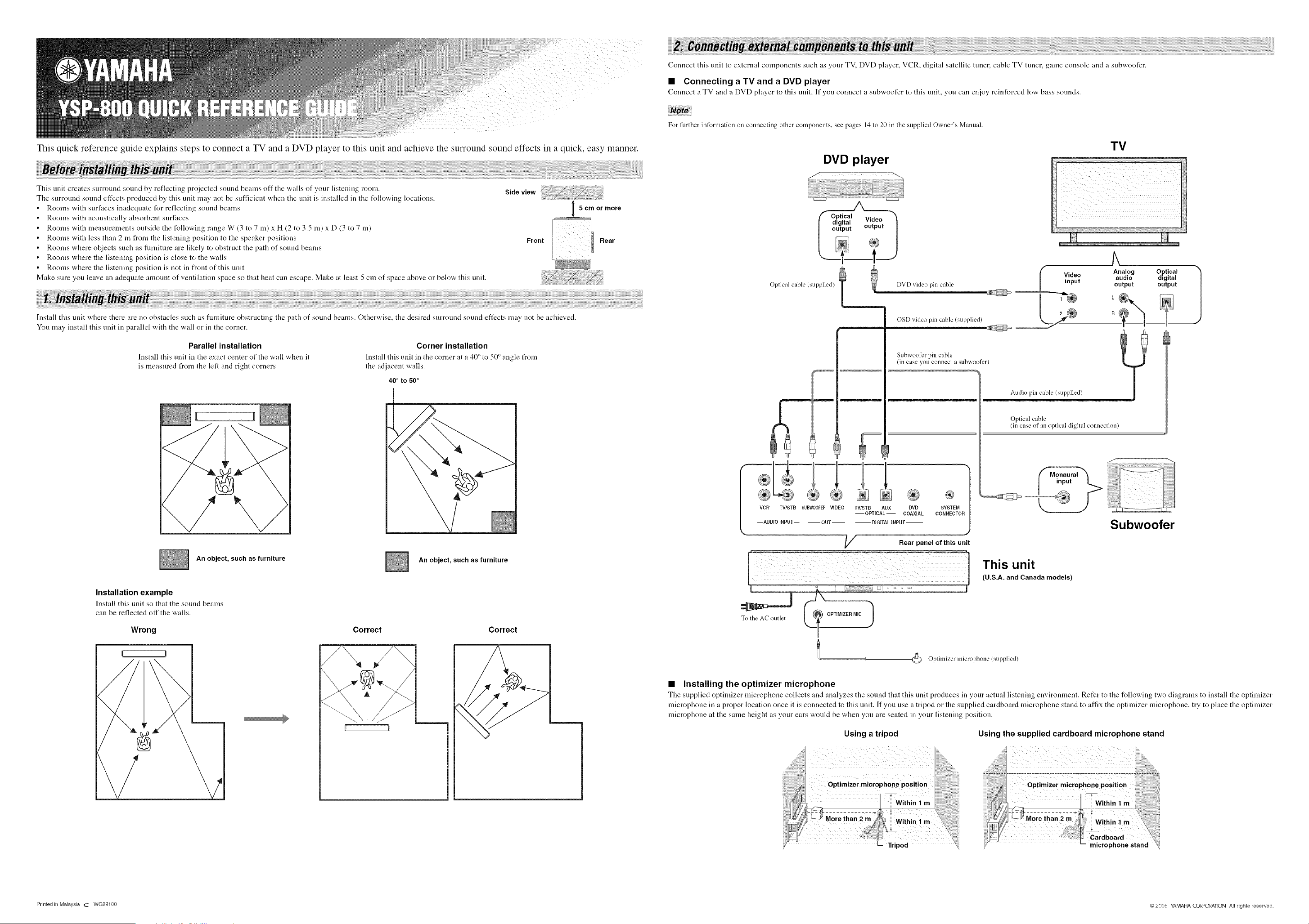
This quick reference guide explains steps to connect a TV and a DVD player to this unit and achieve the surround sound effects in a quick, easy manner.
This unit creates surround sound by reflecting proiected sound bealns off the wails of your listeniug room. Side view
The surround sound effects produced by this unit may not be sufficient when the unit is installed in the t_llowing locations.
Rooms with surfaces inadequate for reflecting sound beams 5 cm or more
Rooms with acoustically absorbent surfaces ............
Rootns with measurenlents outside the following range W (3 to 7 m) x H (2 to 3.5 m) x D (3 to 7 m)
Rooms with less than 2 m from the listening position to the speaker positions Front Rear
Rootns where objects such as flmliture are likely to obstruct the path of sound beams
Rooms where the listening position is close to the walls
Rootns where the listening position is not in front of this unit
Make sure you leave an adequate alnount of ventilatiou space so that heat can escape. Make at least 5 cm of space above or below this unit.
Install this unit where there are no obstacles such as flirniture obstructing the path of sound bealns. Otherwise, the desired surround sound effects lnay not be achieved.
You tnay install this unit in parallel with the wall or in the corner.
Parallel installation
Install this unit in the exact center of the wall when it
is lneasured froth the left and right corners.
Corner installation
Install this unit in tile corner at a 40 ° to 50 ° angle from
the adjacent walls.
40 ° to 50 °
I D
\
An object, such as furniture
An object, such as furniture
Installation example
Install this unit so that the sound beams
can be reflected off the walls.
Wrong Correct Correct
\
{ 1
Connect this unit to external cotnponents such as your TV, DVD player, VCR, digital satellite tuner, cable TV tuner, game console and a subwoofer.
• Connecting a TV and a DVD player
Connect a TV and a DVD player to this unit. If you connect a subwoofer to this unit, you can enjoy reinforced low bass sounds.
For further information on connecting other con/lxments, see pages 14 to 20 in the supplied Owner's Manual.
DVD player
Oplical cable (supplied) DVD video pin cable
OSD video pin cable (supplied)
TV
i_ ii ii ii i i i
Subwoofer pin cable
®
VCR TV/STB SUBWOOFERVIDEO TV/STB AUX DVD SYSTEM
--OPTICAL-- COAXIAL CONNECTOR
-- AUDIO INPUT-- OUT DIGITAL INPUT'--
_/_ Rear panel of this unit
??i;;;;;;; ¸:%¸¸¸¸¸)i_;_)?i;;;;;;; ;;;; ;;;; ;;;;;;;; ;;;; ;;;;;;;;;;;; ;;;; ;;;; ;;;;;;;; ;7;i¸i:__;_?:; _;;;;
Analog Optical
Video audio digital
input output output
Oplical cable
!in case of an optical digital connection)
Subwoofer
I
To Ihe AC outlet
OPTIMIZER MIC 1
I II
This unit
(U.S.A. and Canada models)
I
Oplimizer microphone (supplied)
• Installing the optimizer microphone
The supplied optimizer microphone collects and analyzes the soui_M that this ui_lit produces ill your actual listeniug environtneut. Refer to the following two diagrams to install tile optimizer
microphone in a proper location once it is connected to this unit. If you use a tripod or the supplied cardboard microphone stand to affix the optimizer microphone, try to place the optimizer
microphone at the same height as your ears would be when you are seated in your listening position.
Using a tripod Using the supplied cardboard microphone stand
Printed in Malaysia (2 WG29100 @2005 YAMAHA CORPORATION All rights reserved.
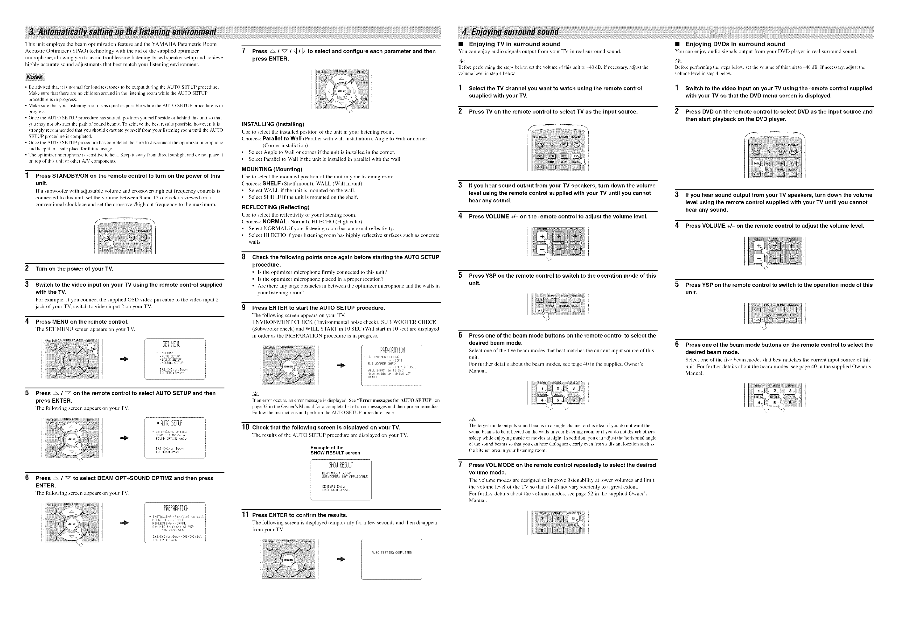
This unit employs the beam optimization feature and the YAMAHA Parametric Room
Acoustic Optimizer (YPAO) technology with the aid of the supplied optimizer
microphone, allowing you to avoid troublesome listening-based speaker setup and achieve
highly accurate sound adjustments that best match your listening environment.
• Be advised that it is normal lk>rloud test tones to be output during the AUTO SETUP procedure.
Make sure that there are no children around in the listening room while the AUTO SETUP
procedure is in progress.
• Make sure that your listening room is as quiet as possible while the AUTO SETUP procedure is in
progress.
• Once the AUTO SETUP procedure has started, position yourself beside or behind this unit so that
you may not obstruct the path of sound beams. To achieve the best results possible, however, it is
strongly recommended that you should evacuate yourself fron/your listening room until the AUTO
SETUP procedure is completed.
• Once the AUTO SETUP procedure has completed, be sure to disconnect the optimizer microphone
and keep it in a safe place for future usage.
• The optimizer microphone is sensitive to heat. Keep it away l?um direct sunlight and do not place it
on top of this unit or other A/V components.
Press STANDBY/ON on the remote control to turn on the power of this
unit.
IX"a subwoofer "a,ith adjustable volume and crossover/high cut frequency controls is
connected to this unit, set the volume between 9 and 12 o'clock as viewed on a
conventional clockfuce and set the crossover/high cut frequency to the maximum.
2
3
4
Turn on the power of your TV.
Switch to the video input on your TV using the remote control supplied
with the TV.
For example, if you connect the supplied OSD video pin cable to the video input 2
jack of your TM switch to video input 2 on your TV.
Press MENU on the remote control.
The SET MENU screen appears on your TV.
'=_ iiEHil
=,_i I ,
waJ .....
+ , HEHOW,'
, AOTll 5ETIJF
I1_ , BASTE SETIJF
, HFff4UFIL SETIJF
[&] • [_] : IJF "Dottel
[ENTER : ErUer
Press z& / "_ on the remote control to select AUTO SETUP and then
press ENTER.
The following screen appears on your TV.
i==!i%== i=r=,'=_IP=
==UJiU 2,EiUF
+ BEAPI+SOUND OFTIHZ
BEF/bl OFTIHZ or,lJ
50iJND OFTIr'IZ or,IJ
[_3 "£_2 : lip, Dor_ir,
[ENI ER :Enter
Press _ / _ to select BEAM OPT+SOUND OPTIMZ and then press
ENTER.
The following screen appears on your TV.
]
+ INSTALLmG..F'_PMIel to hiM1|
HOUNT ING_ _ , , SHELF
/
REFLEI TING- ,NORMAL
Set r'llC m fror,t of 'gSF
PIlH 2r,,'6_ 5ft
[A] • [_f] : IJF "Doialrl [4 [hi : 5e I
EEHTER =St _r-t
7 Press _ / _ / q / F to select and configure each parameter and then
press ENTER.
"';,'5
INSTALLING (Installing)
Use to select the installed position of the unit in your listening room.
Choices: Parallel to Wall (Parallel with wall installation), Angle to Wull or corner
(Corner installation)
Select Angle to Wull or corner if the unit is installed in the corner.
Select Parallel to Wall if the unit is installed in parallel with the wall.
MOUNTING (Mounting)
Use to select the mounted position of tire unit in your listening room.
Choices: SHELF (Shelf mount), WALL (Wull mount)
Select WALL if the unit is mounted on the wall.
Select SHELF if the unit is mounted on the shelf.
REFLECTING (Reflecting)
Use to select the reflectivity of your listening room.
Choices: NORMAL (Normal), HI ECHO (High echo)
Select NORMAL if your listening room has a normal reflectivity.
Select HI ECHO if your listening room has highly reflective surfaces such as concrete
walls.
Check the following points once again before starting the AUTO SETUP
procedure.
• Is the optinfizer microphone firmly connected to this unit?
• Is the optimizer microphone placed in a proper location'?
• Are there any large obstacles in between the optimizer microphone and the walls in
your listening room?
Press ENTER to start the AUTO SETUP procedure.
The %llowing screen appears on your TV.
ENVIRONMENT CHECK (Environmental noise check), SUB WOOFER CHECK
(Subwoofer check) and WILL START in 10 SEC (Will start in 10 sec) are displayed
in order as the PREPARATION procedure is in progress.
ENUIRONHEHT CHECK
... D:$::2
.:JiJB UOOFER CHECK
,,, [NOT Itl IJSE]
I,JILL STAR] ¸ in I8 5EC
Ho_Je aside or "¸ behind ','SF¸
If all error occurs, an error message is displayed. See "Error messages lbr AUTO SETUP" on
page 33 ill the Owner's Manual lor a complete list of error messages and their proper remedies.
Follow the instructions and perform the AUTO SETUP procedure again.
10 Check that the following screen is displayed on your TV.
The results of the AUTO SETUP procedure are displayed on your TV.
Example of the
SHOW RESULT screen
I=H==dl _=,.'===Ui,'=
2,i%¢1F,r;:_I.ILi
BEAM PIODE: 5BEAM
SIJBI,ImFER: NOT F4FPLICABLE
[ENTER] :Enter
[RETIJRb[ : Cancel
11 Press ENTER to confirm the results.
The following screen is displayed temporarily for a few seconds and then disappear
from your TV.
AUTO SETTING COHF'LETED
• Enjoying TV in surround sound
You can enjoy audio signals output from your TV in real surround souud.
Belore performing the steps below, set the volume of this unit to 40 dB. If necessary, a@lst the
vohune level in step 4 below.
1 Select the TV channel you want to watch using the remote control
supplied with your TV.
2 Press TV on the remote control to select TV as the input source.
If you hear sound output from your TV speakers, turn down the volume
level using the remote control supplied with your TV until you cannot
hear any sound.
4 Press VOLUME +/- on the remote control to adjust the volume level.
5 Press YSP on the remote control to switch to the operation mode of this
unit.
Press one of the beam mode buttons on the remote control to select the
desired beam mode.
Select one of the five beam modes that best matches the current input source of this
unit.
For fimher details about the beam modes, see page 40 in the supplied Owner's
Manual.
"t:." ":,/:-
The target mode outputs sound beams in a single channel and is ideal if you do not want the
Solmd beams to be reflected on the walls in your listening room or if you do not disturb others
asleep while ei\joyiug nmsic or movies at night. In addition, you can adjust the horizontal angle
of the sound beams so that you can hear dialogues clearly even from a distant location such as
the kitchen area in your listening romn.
Press VOL MODE on the remote control repeatedly to select the desired
volume mode.
The volume modes are desigued to improve listenubility at lo'a, er volumes and limit
the vohnne level of the TV so that it will not vary suddenly to u great extent.
For fimher details about the volume modes, see page 52 in the supplied Owner's
Manual.
• Enjoying DVDs in surround sound
You can enjoy audio signals output from your DVD phtyer ill real surround sound.
Belore performing the steps below, set the volume of this unit to _,0 dB. If necessary, at[just the
volunm level in step 4 below.
1 Switch to the video input on your TV using the remote control supplied
with your TV so that the DVD menu screen is displayed.
2 Press DVD on the remote control to select DVD as the input source and
then start playback on the DVD player.
If you hear sound output from your TV speakers, turn down the volume
level using the remote control supplied with your TV until you cannot
hear any sound.
4 Press VOLUME +/- on the remote control to adjust the volume level.
"-;,,'>
5 Press YSP on the remote control to switch to the operation mode of this
unit.
Press one of the beam mode buttons on the remote control to select the
desired beam mode.
Select one of the five beam modes that best matches tire current input source of this
unit. For fimher details about the beam modes, see page 40 in the supplied Owner's
Manual.
,,,..r ,,. :
,.,, ,,,