Loading ...
Loading ...
Loading ...
920-087-04 (8-05)
AppendixA: ElectricalWiringfor265 VoltModels
NOTE: Itis recommended thatthe PXSB subbase assembly,the PXCJ conduit kitand the PXDS disconnect switch be installed on all
hardwired units. Ifinstalling aflush-floor mounted unit,make provisionsfor all the line voltage power leads andconduit to be removed
for ease of maintenance and service to the chassis.
Toinstall the line voltage powerleads and conduit to the chassis, follow the instructions below.
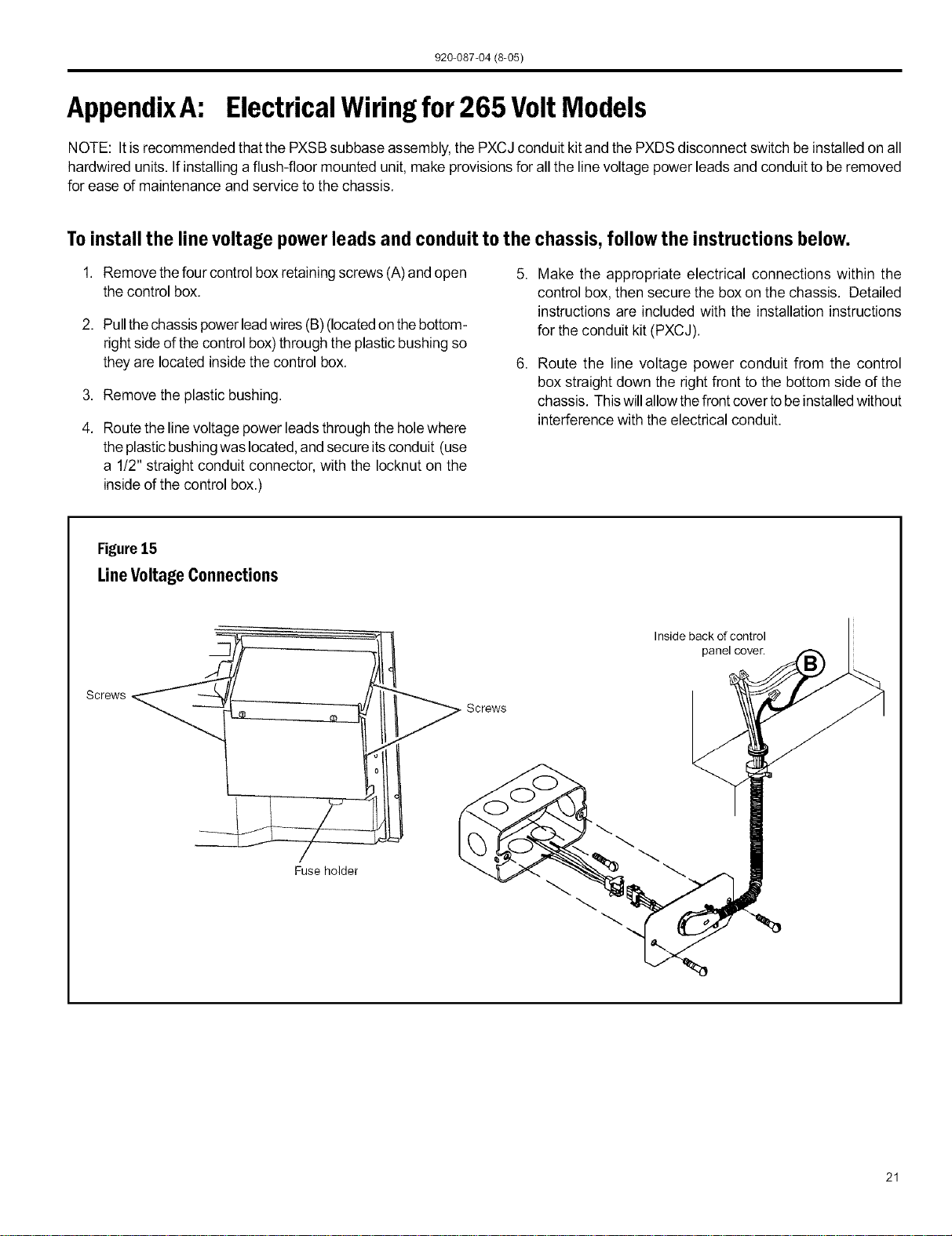
1. Remove thefour control boxretainingscrews (A)and open
the control box.
2. Pull thechassispowerleadwires (B) (locatedonthebottom-
rightside of the control box)through the plasticbushing so
they are located insidethe control box.
3. Remove the plastic bushing.
4. Route the linevoltage power leads through the holewhere
the plasticbushingwas located,and secure itsconduit (use
a 1!2" straight conduit connector, with the Iocknut on the
insideof the control box.)
5. Make the appropriate electrical connections within the
control box, then secure the box on the chassis. Detailed
instructions are included with the installation instructions
for the conduit kit (PXCJ).
6. Route the line voltage power conduit from the control
box straight down the right front to the bottom side of the
chassis. Thiswillallow thefront cover tobeinstalledwithout
interference with the electrical conduit.
Figure15
LineVoltageConnections
Screws
Fuse holder
Screws
Inside back of control
panel cover.
21
Loading ...
Loading ...
Loading ...