INSTALLATION &
OPERATION GUIDE
PTAC
PACKAGED TERMINAL
AIR CONDITIONERS
& HEAT PUMPS
Standard Control
Remote Thermostat
Seacoast Protected
920-087-04 (8-05)
920-087-04 (8-05)
TableofContents
Unit Components ...............................................................................................................................................................................................2
Model Number Code..........................................................................................................................................................................................3
Installation Recommendations ..........................................................................................................................................................................4
Friedrich Digital Control Features .................................................................................................................................................................5-6
Drain Kit Installation ........................................................................................................................................................................................7-8
Wall Sleeve Installation .................................................................................................................................................................................9-10
Deep Wall Installation ......................................................................................................................................................................................11
Standard Grille Installation ..............................................................................................................................................................................12
Electrical Rating Tables ...................................................................................................................................................................................13
Power Cord Information ...................................................................................................................................................................................13
Installation Checklist ........................................................................................................................................................................................14
Chassis Installation .....................................................................................................................................................................................14-15
Digital Control User Input Configuration .........................................................................................................................................................16
Operation ..........................................................................................................................................................................................................17
Remote Thermostat and Low Voltage Control Connections .........................................................................................................................18
Desk Control Terminals ...................................................................................................................................................................................19
Auxiliary Fan Control........................................................................................................................................................................................19
FreshAir Vent Control ......................................................................................................................................................................................19
Air Discharge Grille ..........................................................................................................................................................................................19
Start-up Checklist .............................................................................................................................................................................................20
Appendix A: Electrical Wiring for 265 V Models............................................................................................................................................21
Routine Maintenance .......................................................................................................................................................................................22
Basic Troubleshooting Techniques .................................................................................................................................................................23
Digital Control Diagnostics and Test Mode ....................................................................................................................................................24
Accessories ................................................................................................................................................................................................25-26
Warranty ...........................................................................................................................................................................................................27
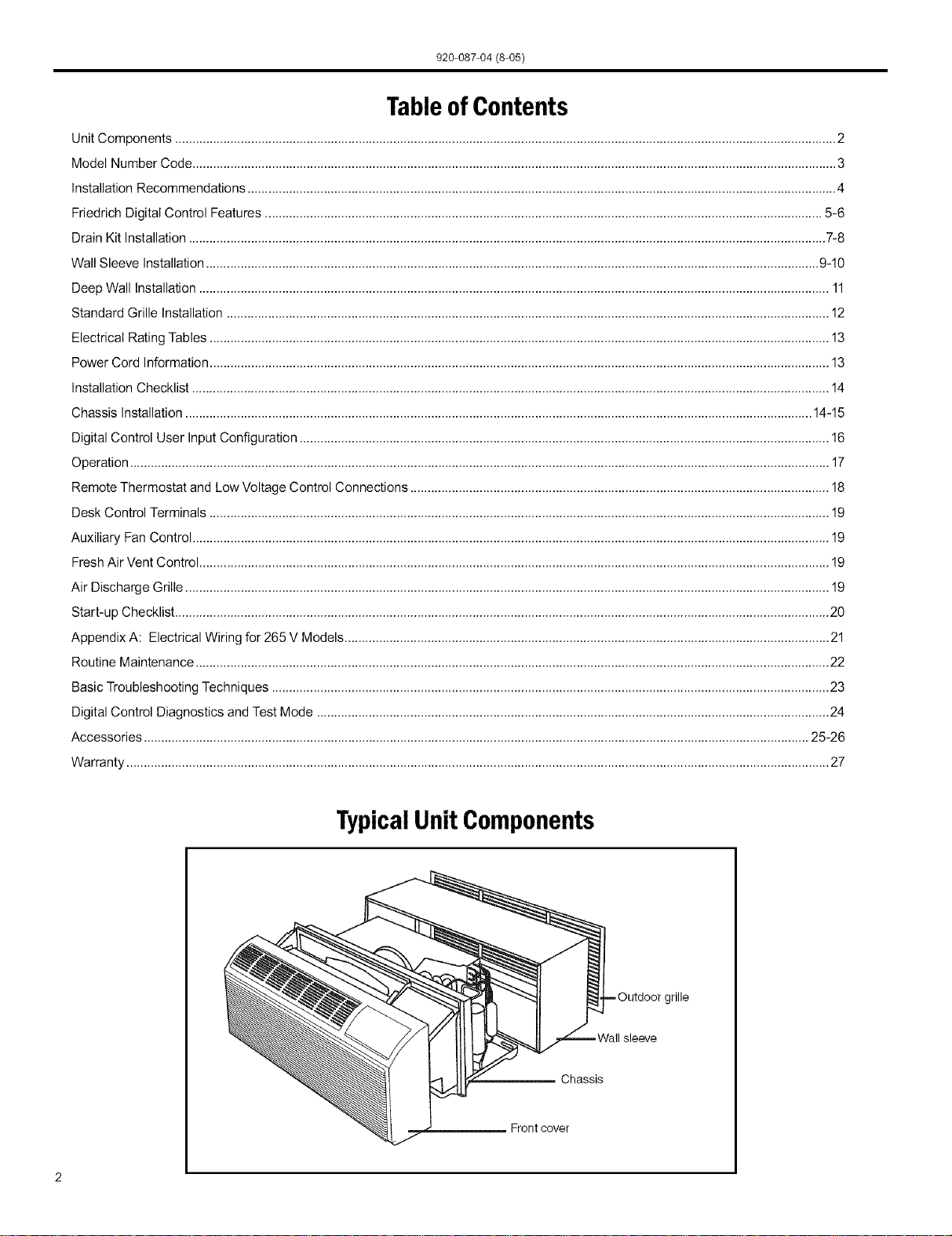
TypicalUnit Components
Chassis
Frontcover
jrille
920-087-04 (8-05)
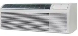
Thank you for your decision to purchase the newly designed Friedrich Packaged Terminal Air Conditioner (PTAC). We are
confident that you will find this unit a quiet and efficient example of Friedrich reliability.
This Installation and Operation Manual has been designed to insure maximum satisfaction in the performance of your unit.
For years of trouble-free service, please follow the installation instructions closely. We cannot overemphasize the importance
of proper installation. We have added new information to the basic instructions to help you achieve success.
Remember, proper installation is not difficult but it is essential.
I
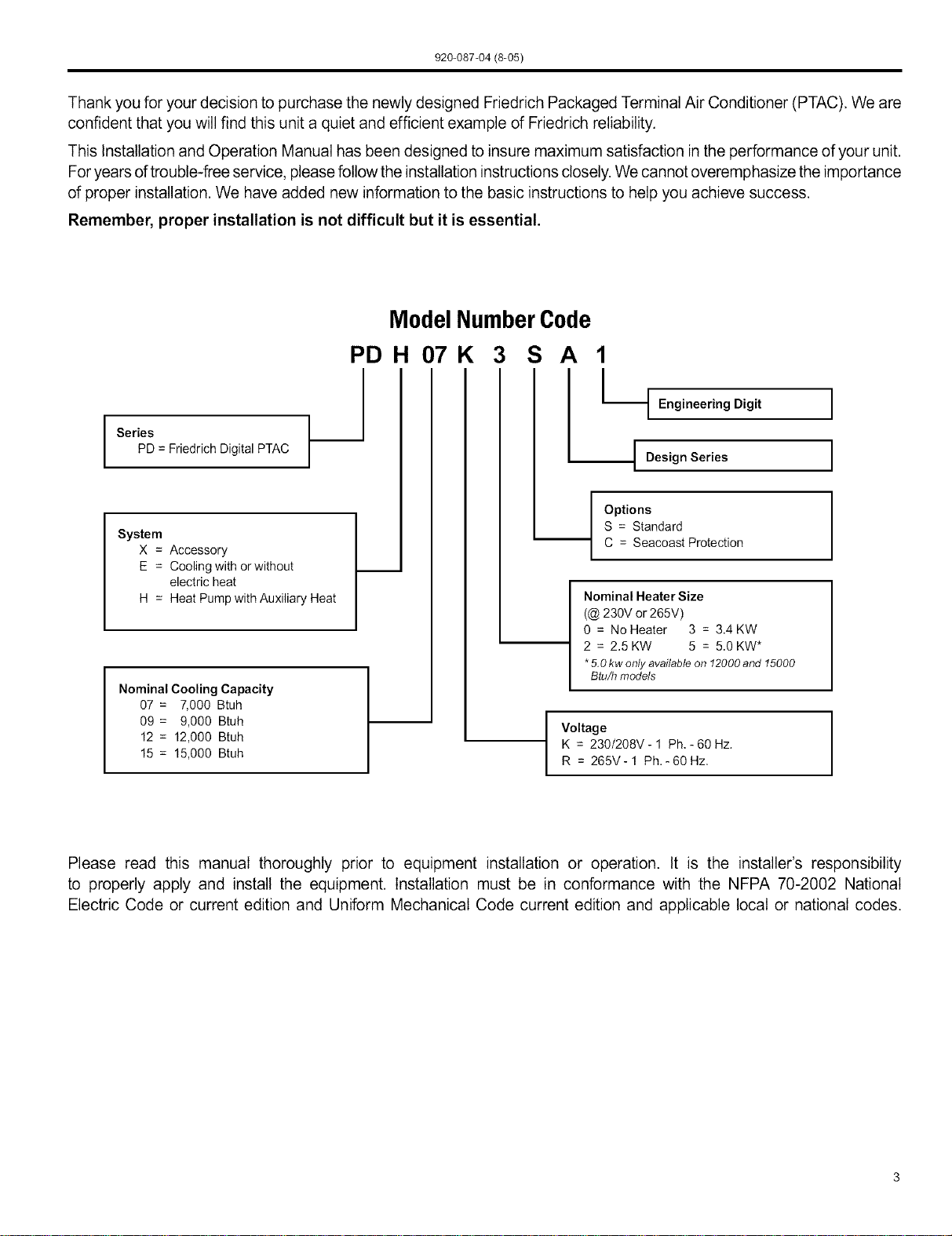
Series
PD = Friedrich Digital PTAC
System
X = Accessory
E = Cooling with orwithout
electric heat
H = Heat Pump with Auxiliary Heat
Nominal Cooling Capacity
07 = 7,000 Btuh
09 = 9,000 Btuh
12 = 12,000 Btuh
15 = 15,000 Btuh
ModelNumberCode
PDH 07K 3 S A 1
I_
t Engineering Digit
I DesignSeries
Options
S = Standard
C = Seacoast Protection
Nominal Heater Size
(@ 230V or 265V)
0 = No Heater 3 = 3.4 KW
2 = 2.5 KW 5 = 5.0 KW*
*5.0kw onlyavailable on 12000and 15000
Btu/h models
I
Voltage
K = 230/208V - 1 Ph, - 60 Hz.
R = 265V-1 Ph.-60Hz,
I
I
I
I
Please read this manual thoroughly prior to equipment installation or operation. It is the installer's responsibility
to properly apply and install the equipment. Installation must be in conformance with the NFPA 70-2002 National
Electric Code or current edition and Uniform Mechanical Code current edition and applicable local or national codes.
920-087-04 (8-05)
PTACInstallation Recommendations
ForproperPTACunit performance and maximum operating life please refer to the minimum installation clearances below:
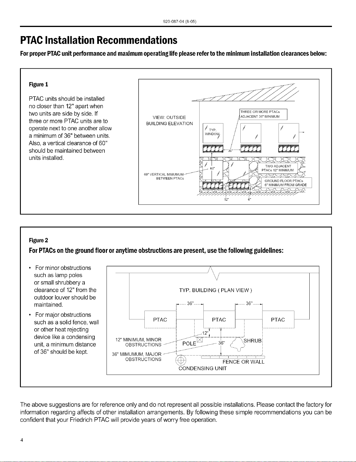
FigureI
PTAC units should be installed
no closer than 12" apart when
two units are side by side. If
three or more PTAC units are to
operate next to one another allow
a minimum of 36" between units.
Also, a vertical clearance of 60"
should be maintained between
units installed.
VIEW: OUTSIDE
BUILDING ELEVATION
BETWEEN PTACs
12"
THREE OR MORE PTACs
A.DJACENT 36" MINIMUM
Figure2
For PTACson the ground floor or anytime obstructions are present, use the following guidelines:
For minor obstructions
such as lamp poles
or small shrubbery a
clearance of 12" from the
outdoor louver should be
maintained.
For major obstructions
such as a solid fence, wall
or other heat rejecting
device like a condensing
unit, a minimum distance
of 36" should be kept.
?\
J \
TYP. BUILDING ( PLAN VIEW )
...............3G,,.............. /_ 3G,,.1
7
PTAC PTAC / PTAC
J
............................................................., i_:,._..................._...........................j ,.............................................................
OBSTRUCTIONS _ POLE_j.J--- 3,_5 ¢_ ._
/_-- JJ / .....',J I
36" MIMUMUM MAJOR _'_ _ 1 J
OBSTRUCTIONS _ FENCEORWALL
CONDENSINGUNIT
The above suggestions are for reference only and do not represent all possible installations. Please contact the factory for
information regarding affects of other installation arrangements. By following these simple recommendations you can be
confident that your Ffiedrich PTAC will provide years of worry free operation.
920-087-04 (8-05)
FriedrichDigitalControlFeatures
The new Friedrich digital PTAC has state of the art features to improve guestcomfort, indoor air quality and conserve energy.
Through the use of specifically designed control software for the PTAC industry Ffiedfich has accomplished what other Manufactur-
er's haveonly attempted - a quiet, dependable, affordable and easy to use PTAC.
Below is a list of standard features on every Friedrich PTACand their benefit to the owner.
Digital Temperature Bydigitallymonitoringdesiredroomtemperaturetheroomiscontrolledmorepreciselythanconventionalsystems.Thelarge,easy
Readout toreadLEDdisplaycanshoweitherset-pointor actualroomtemperatureasselectedbyowner.
Whentheunitispoweredofftheunitcanbereturneddirectlytoheatingorcoolingmodebypressingthe 'Heat'or 'Coot'buttons
One-Touch Operation withouttheconfusingpowerupsequenceofsomecontrols.One-touchcontroltakesguessworkoutofunitcontroldeliveringamore
enjoyableexperienceandeliminatingfront-deskcalls.
Individual Mode and ByhavingseparatecontrolbuttonsandindicatorsforbothfanandmodesettingstheFriedrichdigitalcontroleliminatestheconfu-
Fan Control Buttons sionofpreviousdigitalPTACs.Theaccuratetemperaturesettingprovidesgreaterguestcomfortthanothersystems.
Thefanstartandstopdelayspreventabruptchangesinroomacousticsduetothecompressorenergizingorstoppingimmediately.
Quiet Start/Stop
Uponcallforcoolingorheatingtheunitfanwillrunforfivesecondspriortoenergizingthecompressor.Also,thefanoffdelayallows
Fan Delay for"free cooling"byutilizingthealreadycoolindoorcoiltoitsmaximumcapacitybyrunningfor30secondsafterthecompressor.
Remote Thermostat Someapplicationsrequirethe useofa wallmountedthermostat.All newFriedrichPTACsmaybeswitchedfromunitcontrolto
Operation remotethermostatcontroleasilywithouttheneedtoordera specialmodeloraccessorykit,
Wireless Remote Guestscanadjustthetemperatureandmodeoftheunitthroughtheused anoptionalhandheldwirelessremote,improvingguest
Control Ready comfortandrelaxation.
Internal Diagnostic ThenewFriedrichdigitalPTACfeaturesa selfdiagnosticprogramthatcanalertmaintenancetocomponentfailuresoroperating
Program problems,Theinternaldiagnosticprogramsavespropertiesvaluabletimewhendiagnosingrunningproblems.
Service ErrorCode Theself diagnosisprogramwilIalsostoreerrorcodesinmemoryif certainconditionsoccurand correctthemselvessuchasex-
tremehighorlowoperatingconditionsor activationoftheroomfreezeprotectionfeature,Storingerrorcodescanhelpproperties
Storage determineiftheunitfacedobscureconditionsorifanerroroccurredandcorrecteditself.
Constant Comfort Theon-boardprocessormonitorstimebetweendemandcycles(heatorcool)andwilIcyclethefanevery9 minutestosamplethe
roomconditionanddetermineifthedesiredconditionsaremet.Thisallowstheroomtohavesimilarbenefitstoaremotemounted
Room Monitoring statwithoutthecomplicationor costofawailmountedthermostat.
Electronic Temperature Bylimitingtheoperatingrangethepropertycansaveenergybyeliminating"maxcoot"or"maxheat"situationscommonwitholder
uncontrolledsystems.Thenewelectroniccontrolallowsownerstosetoperatingrangesforbothheatingandcoolingindependently
Limiting ofoneanother.
RoomFreeze
Protection
RandomCompressor
Restart
DigitalDefrost
Thermostat
WhenthePTACsensesthattheindoorroomtemperaturehasfallento40°Ftheunitwillcycleonhighfanandtheelectricstripheat
toraisetheroomtemperatureto46°Fthencycleoff again.Thisfeatureworksregardlessofthemodeselectedandcanbeturned
off.ThecontrolwillalsostoretheRoomFreezecycleintheservicecodememoryfor retrievalata laterdate.Thisfeatureensures
thatunoccupiedroomsdo notreachfreezinglevelswheredamagecanoccurtoplumbingandfixtures.
Multiplecompressorsstartingatoncecanoftencauseelectricaloverloadsandprematureunitfailure.Therandomrestartdelay
eliminatesmultipleunitsfromstartingatoncefollowingapoweroutageor initialpowerup,Thecompressordelaywillrangefrom
180to240seconds.
ThenewFriedrichPTACusesadigitalthermostattoaccuratelymonitortheoutdoorcoilconditionstoallowthe heatpumpto run
wheneverconditionsarecorrect,Runningthe PTACin heatpumpmodesaveenergyandreducesoperatingcosts.Thedigital
thermostatallowsmaximizationofheatpumpruntime.
920-087-04 (8-05)
FriedrichDigital ControlFeaturesContinued
Instant Heat Heatpumpmodelswillautomaticallyruntheelectricheatertoquicklybringtheroomuptotemperaturewheninitiallyenergized,
thenreturntoheatpumpmode.Thisensuresthattheroomisbroughtuptotemperaturequicklywithouttheusualdelayassoci-
Heat Pump Mode atedwithheatpumpunits.
Thedigitalcontrolmonitorsindoorconditionstoensurethattheroomtemperatureiswithinfivedegreesofthesetpoint.Ifneces-
Even Heat Monitoring sarytheunitwillcycletheelectricheattomaintainthetemperature.Thisfeatureensuresguestcomfortbydeliveringtheheating
benefitsofanelectricheaterwhilemaintainingtheefficiencybenefitsofa heatpump.
Theownermaychoosebetweenfancyclingorfancontinuousmodebasedonpropertypreference.(Note:Evenheatmonitor-
Fan Cycle Control ingandquietstart/stopfandelayonlyoperateinfancyclemode)Fancontinuousmodeisusedtokeepconstantairflowcircula-
tionintheroomduringatItimestheunitis'ON'.Fancyclewillconserveenergybyonlyoperatingthefanwhilethecompressor
orelectricheaterisoperating.
Inthe eventofa compressorfailureinheatpumpmodethecompressormaybelockedout toprovideheatthroughtheresis-
Emergency Heat Override tanceheater.Thisfeatureensuresthatevenintheunlikelyeventofacompressorfailurethe roomtemperaturecanbemain-
taineduntilthecompressorcanbeserviced.
All FriedrichdigitalPTACshavelowvoltageterminalsreadytoconnectadeskcontrolenergymanagementsystem.Control-
Desk Control Ready lingtheunitfroma remotelocationlikethefrontdeskcan reduceenergyusageandrequiresnoadditionalaccessoriesatthe
PTAC.
Thefrostsensorprotectsthecompressorfromdamageintheeventthatairflowisreducedorlowoutdoortemperaturescause
Indoor Coil Frost Sensor theindoorcoiltofreeze.Whentheindoorcoilreaches30°Fthecompressorisdiabtedandthefancontinuestooperatebased
ondemand,Oncethecoiltemperaturereturnsto45°Fthecompressorreturnstooperation.
ThenewFriedrichPDseriesunitsfeatureaindoorfansystemdesignthat reducessoundlevelswithoutloweringairflowand
Ultra-Quiet Air System preventingproperaircirculation,
High Efficiency TheFriedrichPTACbenefitsqualitycomponentsandextensivedevelopmenttoensureaquiet,efficientanddependableunit.
Friedrich'ssingIe-motordesignallowsfor enhancedoutdoorairflowandsimplifiesthe unitdesignwithouttheneedforredun-
Single Motor dantcomponents.
Rotary Compressor HighefficiencyrotarycompressorsareusedonallFriedrichPTACsto maximizedurabilityandefficiency.
TheFriedrichPTACfeaturesa24VACterminalfor connectiontoanauxiliaryfanthatmaybeusedtotransferairtoadjoining
Auxiliary Fan Ready rooms.Auxiliaryfanscanprovideconditioningto multipleroomswithoutthe requirementofmultiplePTACunits.
Aluminum Endplates AllFriedrichPTACsarebuiltwith.04"endplatesmadefromaluminumasopposedtosteel.Theendplatesaretypicallythemost
susceptibleareaforcorrosionandaluminumisfar moreresistanttocorrosionthanevencoatedsteel.
OptionalSeacoastprotectionisavailabletoprotecttheoutdoorcoilfromharshenvironments.TheFriedrichSeacoastprocess
Seacoast Protection includesdippingthe entireoutdoorcoilina7-stepcoatingprocessthatprovidessuperiorprotectiontoonlycoatingthefinsof
thecoil.
Top Mounted Anti- All FriedrichPTACreturnairfiltersfeatureananti-microbialelementthathasproventopreventmoldandbacterialgrowthin
laboratorytesting.PDXFTreplacementfilterkitsfeaturethesameanti-microbialagent.Allfiltersarewashableandreusable
microbial Air Filters andareeasilyaccessedfromthetopoftheunitwithouttheremovalofthefrontcover.
FriedrichPTACunitsarecapabieofintroducingupto70CFMofoutsideairintotheconditionedspace.Theoutdoorairpasses
Filtered FreshAir Intake
throughawashablemeshfiltertopreventdebrisfromenteringthe airstream.
920-087-04 (8-05)
Installation Instructions PXDRIODrain Kit
NOTE: Determine whether drain will be located within the wall, on the indoor side, or will drain to the exterior of the building. Follow
appropriate instructions below depending on your particular type of installation.
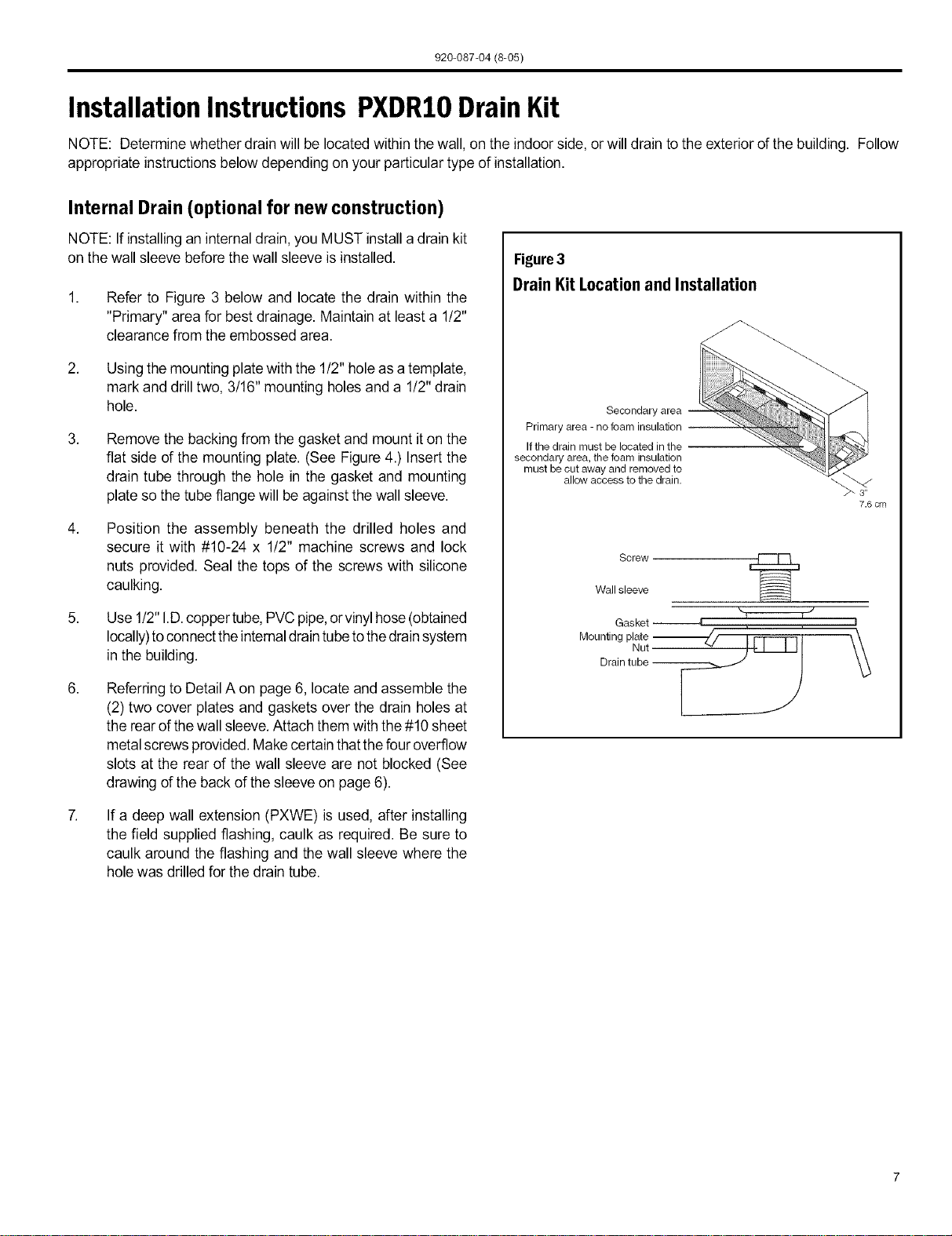
Internal Drain (optional for new construction)
NOTE: If installing an internaldrain, you MUST install a drain kit
on the wall sleeve beforethe wall sleeve is installed.
,
,
,
5,
,
,
Refer to Figure 3 below and locate the drain within the
"Primary" area for best drainage. Maintain at least a 1!2"
clearance from the embossed area.
Using the mounting platewith the 1/2" hole asa template,
mark and drill two, 3/16" mounting holes and a 1/2" drain
hole.
Remove the backing from the gasket and mount iton the
flat side of the mounting plate. (See Figure 4.) Insert the
drain tube through the hole in the gasket and mounting
plate so the tube flange will be against the wall sleeve.
Position the assembly beneath the drilled holes and
secure it with #10-24 x 1/2" machine screws and lock
nuts provided. Seal the tops of the screws with silicone
caulking.
Use 1/2"I.D.coppertube, PVCpipe,orvinyl hose(obtained
locally)toconnectthe internaldraintubetothedrainsystem
in the building.
Referring to Detail A on page 6, locate andassemble the
(2) two cover plates and gaskets over the drain holes at
the rear ofthe wall sleeve.Attach them with the#10 sheet
metalscrews provided.Make certain thatthe four overflow
slots at the rear of the wall sleeve are not blocked (See
drawing of the back of the sleeve onpage 6).
If a deep wall extension (PXWE) is used, after installing
the field supplied flashing, caulk as required. Be sure to
caulk around the flashing and the wall sleeve where the
hole was drilled for the drain tube.
Figure3
DrainKit LocationandInstallation
Secondary area
Primary area - no foam insulation
If the drain must be located in the
secondary area, the foam insulation
must be cut away and removed to
allow access to the drain.
7.6 cm
Screw
Wall sleeve
Gasket 4
Mounting plate -_._/ I Fq---Tq t \\
• Nut_Jl'l I II \\
Drain tube _ I _._
920-087-04(8-05)
ExtemalDrain(for newconstructionor unitreplacement)
When using an external drain system, the condensate is removed through either of two drain holes on the back of the wall sleeve.
Select the drain hole which best meets your drainage situation and install the drain kit. Seal off the other with a cover plate.
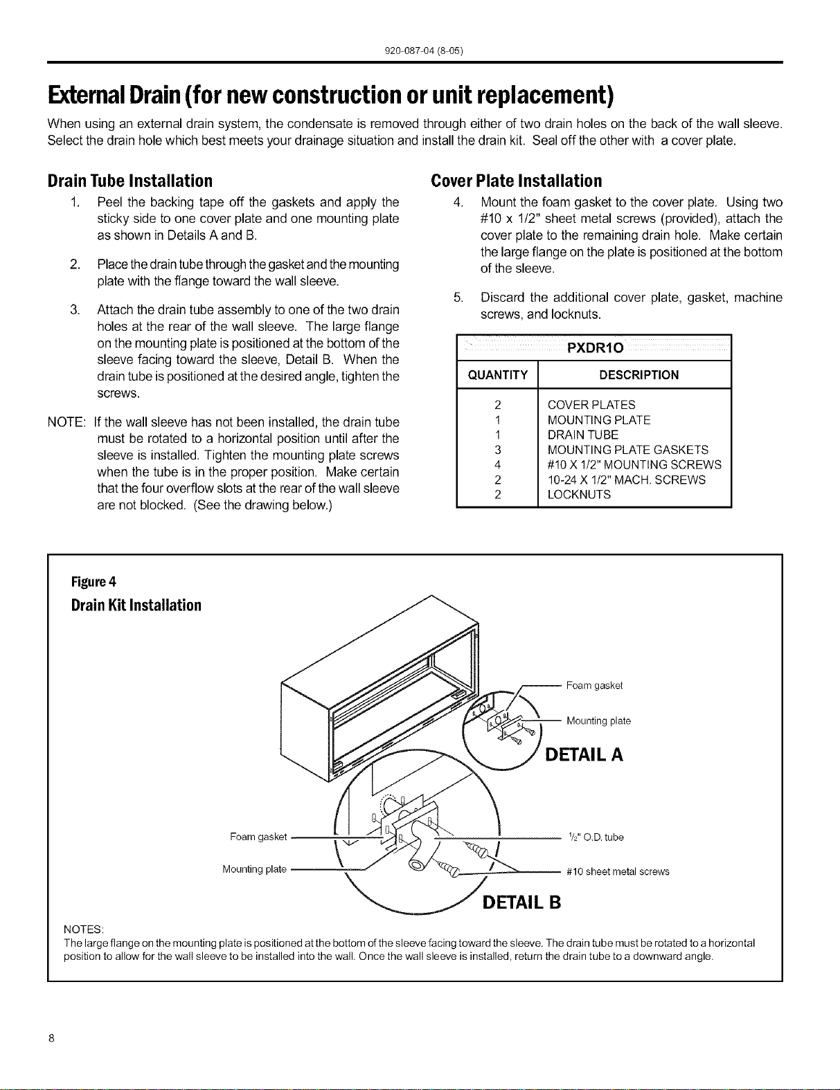
Drain Tube Installation
1. Peel the backing tape off the gaskets and apply the
sticky side to one cover plate and one mounting plate
as shown in DetailsA and B.
2. Placethedraintubethroughthegasketandthemounting
plate with theflange toward the wall sleeve.
Attach the drain tube assembly to one of the two drain
holes at the rear of the wall sleeve. The large flange
on the mounting plateis positioned atthe bottom ofthe
sleeve facing toward the sleeve, Detail B. When the
drain tube ispositioned atthe desired angle,tighten the
screws.
NOTE:
If the wall sleeve has not been installed, the drain tube
must be rotated to a horizontal position until after the
sleeve is installed. Tighten the mounting plate screws
when the tube is in the proper position. Make certain
that thefour overflow slots atthe rear ofthe wall sleeve
are not blocked. (See the drawing below.)
Cover Plate Installation
4. Mount the foam gasket to the cover plate. Using two
#10 x 1!2" sheet metal screws (provided), attach the
cover plate to the remaining drain hole. Make certain
the largeflange on the plate is positioned at the bottom
of the sleeve.
5. Discard the additional cover plate, gasket, machine
screws, and Iocknuts.
QUANTITY DESCRIPTION
2
1
1
3
4
2
2
COVER PLATES
MOUNTING PLATE
DRAIN TUBE
MOUNTING PLATE GASKETS
#10X 1/2" MOUNTING SCREWS
10-24 X 1/2" MACH. SCREWS
LOCKNUTS
Figure4
DrainKitInstallation
-- Foam gasket
Mounting plate
DETAIL A
I V2" O.D. tube
Foam gasket _ /
Mounting plate # 10 sheet metal screws
DETAI L B
NOTES:
The large flange on the mounting plate is positioned atthe bottom of the sleeve facing toward the sleeve. The drain tube must be rotated to a horizontal
position to allow for the wall sleeve to be installed into the wall. Once the wall sleeve is installed, return the drain tube to a downward angle.
920-087-04 (8-05)
WallSleeveInstallation Instructions(PDXWS)
NOTE: Insurethatthe unitisonlyinstalledin awallstructurallyadequatetosupport the unitincludingthesleeve,chassisand accessories.
If the sleeve projects more than 8"into the room, a subbase orother means of support MUST be used. Please readthese instructions
completely before attempting installation.
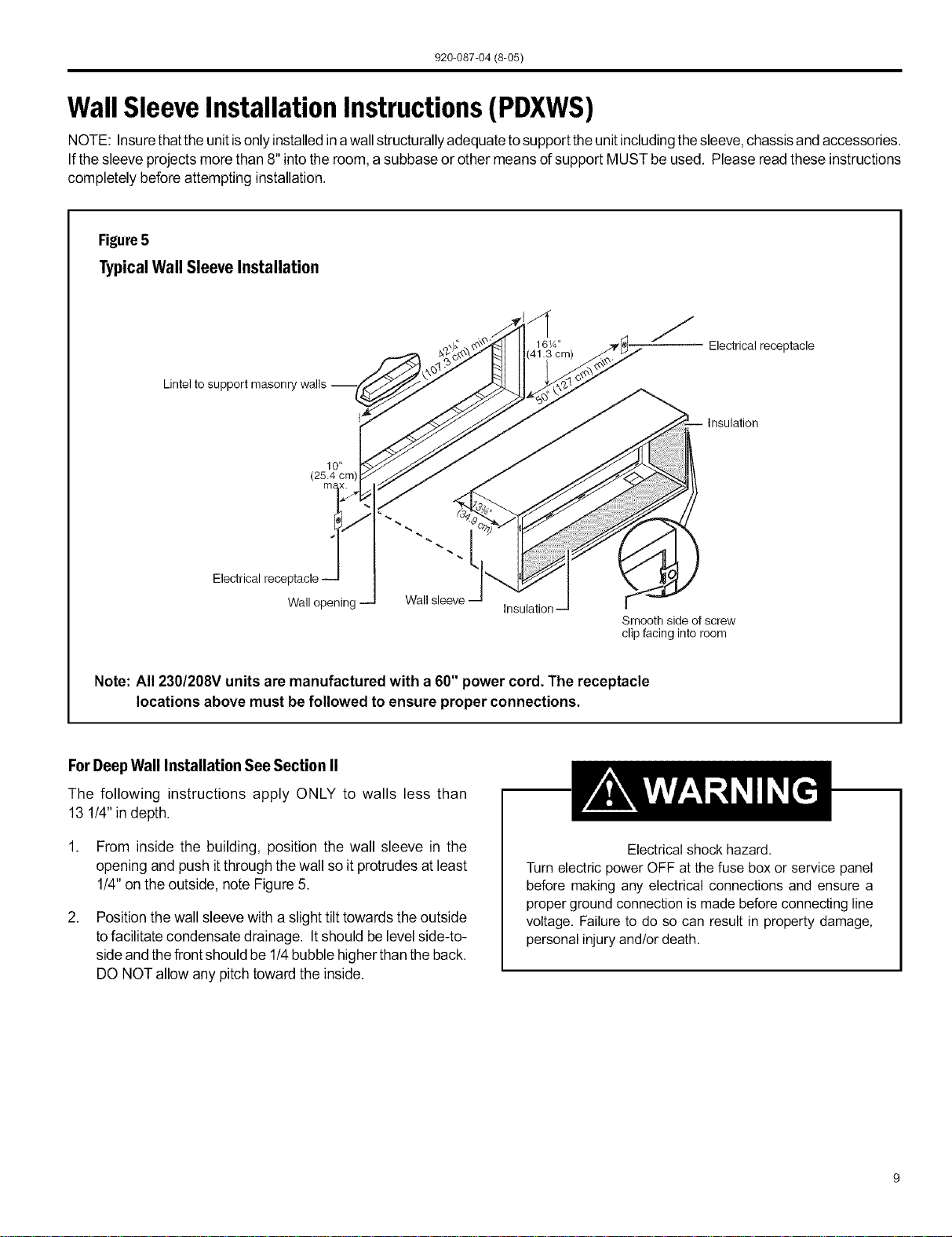
Figure5
Typical Wall Sleeve Installation
Lintel to support masonry
J
16W' Electrical receptacle
Electrical
10 _
(25.4 cm)
m_
Wall opening
Wall sleeve --
insulation--
Smooth side of screw
clip facing into room
Note: All 230/208V units are manufactured with a 60" power cord. The receptacle
locations above must be followed to ensure proper connections.
ForDeep Wall Installation See Section II
The following instructions apply ONLY to walls less than
13 1/4" indepth.
1. From inside the building, position the wall sleeve in the
opening and push itthrough the wall so it protrudes at least
1/4"on the outside, note Figure 5.
,
Position the wall sleeve with a slight tilt towards the outside
tofacilitate condensate drainage. Itshould be levelside-to-
sideand thefront should be 1!4bubble higherthan theback.
DO NOT allow any pitch toward the inside.
Electrical shock hazard.
Turn electric power OFF at the fuse box or service panel
before making any electrical connections and ensure a
proper ground connection is made before connecting line
voltage. Failure to do so can result in property damage,
personal injury and/or death.
920-087-04 (8-05)
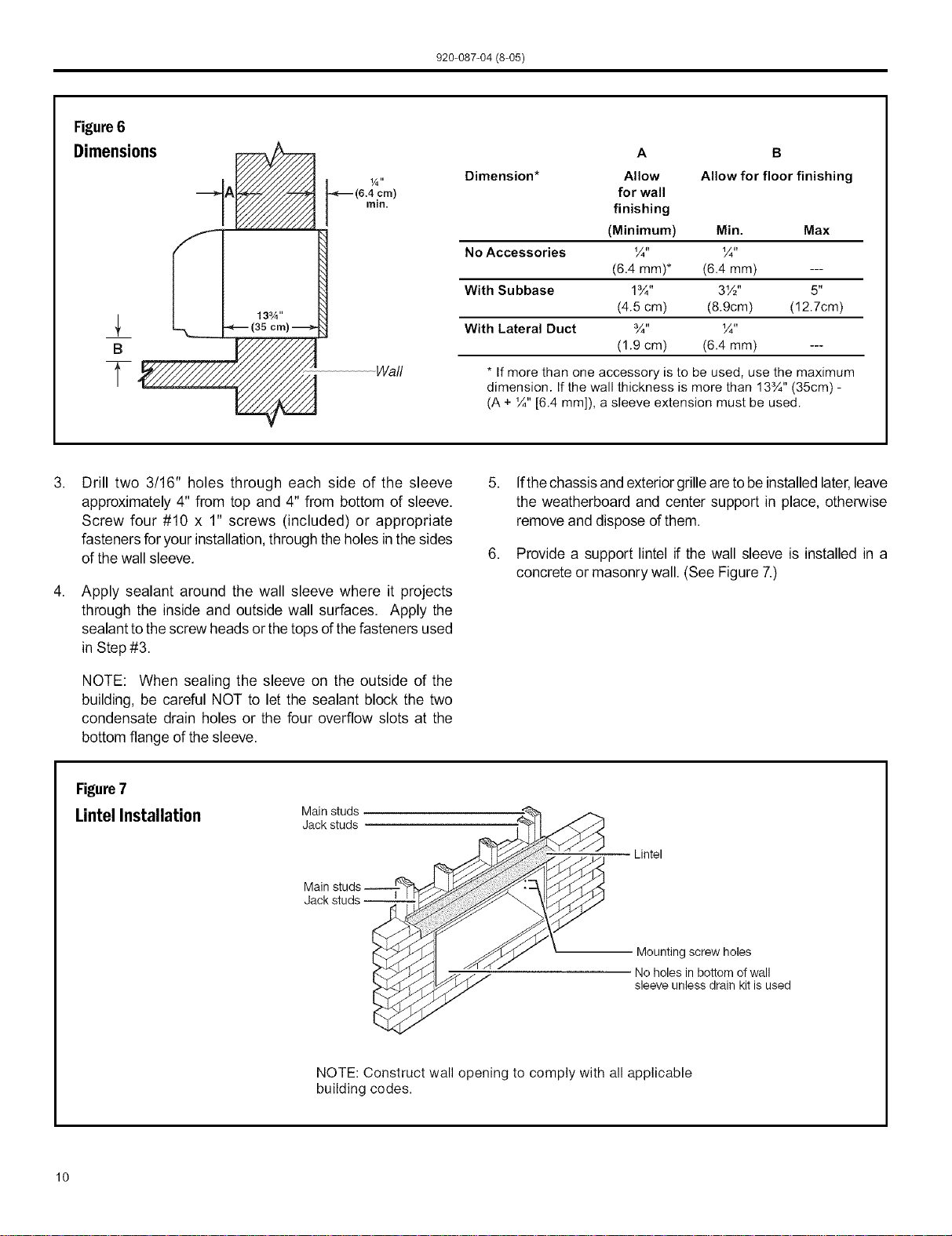
Figure6
Dimensions
B
T
(6.4 cm)
rain.
Wall
A B
Dimension* Allow Allow for floor finishing
for wall
finishing
(Minimum) Min. Max
No Accessories ¼" ¼"
(6.4 mm)* (6.4 mm) ---
With Su bbase 1¾" 3W' 5"
(4.5 cm) (8.9cm) (12.7cm)
With Lateral Duct ¾" ¼"
(1.9 cm) (6.4 mm) ---
* If more than one accessory is to be used, use the maximum
dimension. If the wall thickness is more than 13¾" (35cm) -
(A + ¼" [6.4 mm]), a sleeve extension must be used.
,
Drill two 3/16" holes through each side of the sleeve
approximately 4" from top and 4" from bottom of sleeve.
Screw four #10 x 1" screws (included) or appropriate
fasteners for your installation, through the holes in thesides
of the wall sleeve.
Apply sealant around the wall sleeve where it projects
through the inside and outside wall surfaces. Apply the
sealant to thescrew heads or the tops of thefasteners used
in Step #3.
NOTE: When sealing the sleeve on the outside of the
building, be careful NOT to let the sealant block the two
condensate drain holes or the four overflow slots at the
bottom flange of the sleeve.
Ifthechassis and exterior grilleareto be installed later,leave
the weatherboard and center support in place, otherwise
remove and dispose of them.
Provide a support lintel if the wall sleeve is installed in a
concrete or masonry wall. (See Figure 7.)
Figure7
LintelInstallation Mainstuds
Jack studs
Main
Lintel
Mounting screw holes
No holes in bottom of wall
sleeve unless drain kit is used
NOTE: Construct wall opening to comply with all applicable
building codes.
10
920-087-04 (8-05)
Section II - DeepWall Installation (PXWE)
If thewall isthicker thanallowed in the notes in Figure 6, a sheet
metal wall sleeve extension and flashing MUST be used.
Installation Instructions for the PXWE- 4" Wall
Sleeve Extension
The following points MUST be considered when installing a wall
sleeve extension:
1 Provision must bemade to direct excess condensate from
the back of the wall sleeve into the extension then outside
the building or to a drainage system.
2. Air baffles must be mounted to properly direct air flow to
and from the condenser.
3. Thewall sleeve extension design mustallow for the proper
mounting of the grille.
4. Caulking is required at all sites where condensate or
external water could potentially infiltrate intothe building.
5. Fabricateand install metalflashing inwall to serveas a drip
panel. Refer to drawing for more information.
6. Condensate notchesand overflow slotsmust be kept clear
of sealant and gaskets so condensate can flow freely into
the wall sleeve extension.
NOTE: Improper fabrication or installation of a wall sleeve
extension will impair PTAC performance.
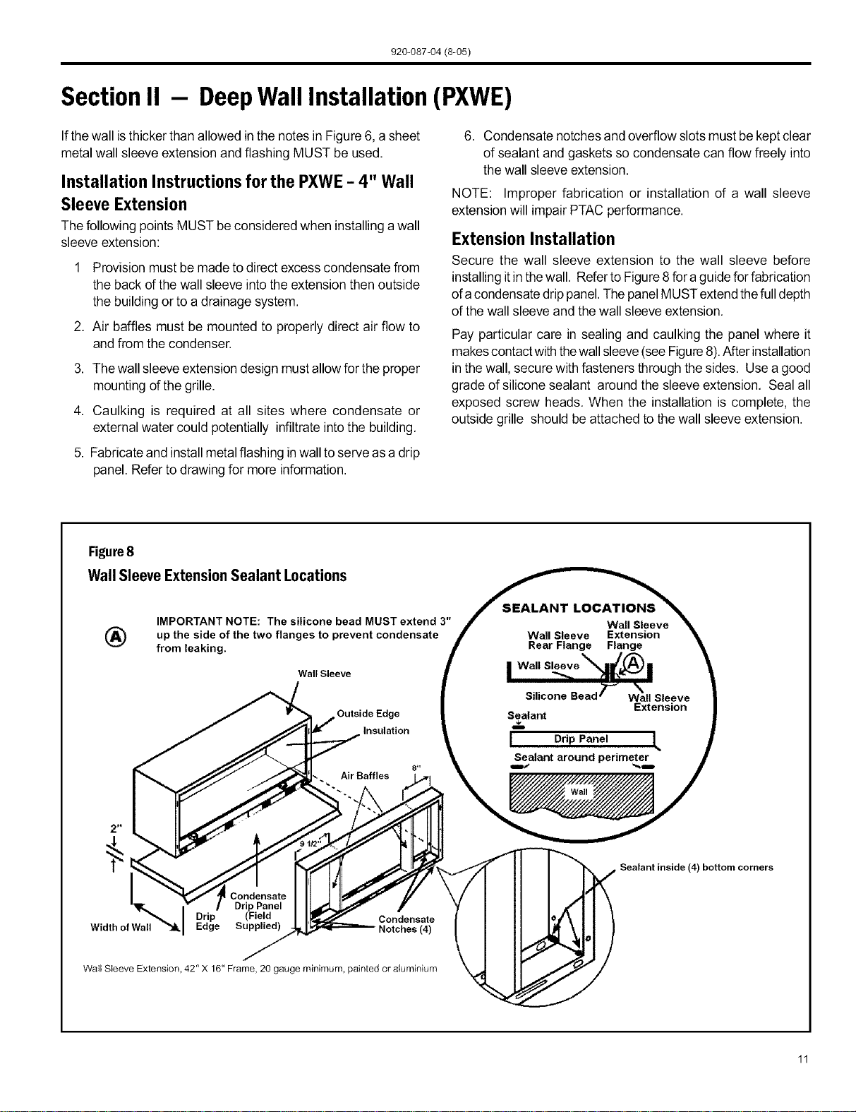
Extension Installation
Secure the wall sleeve extension to the wall sleeve before
installing itin thewall. Refer to Figure8 fora guide forfabrication
of acondensate drip panel.Thepanel MUSTextend thefulldepth
of the wall sleeve and the wall sleeve extension.
Pay particular care in sealing and caulking the panel where it
makescontact with thewall sleeve(seeFigure8).After installation
in thewall, secure with fasteners through the sides. Use a good
grade of silicone sealant around the sleeve extension. Seal all
exposed screw heads. When the installation is complete, the
outside grille should be attached to the wall sleeve extension.
Figure8
WallSleeveExtensionSealant Locations _ION__ s
IMPORTANT NOTE: The silicone bead MUST extend 3" J w=. _l ..... _.
_') up the side of the two flanges to prevent condensate / _X'e'n"si'on _ "_,
from leaking. _!' r_ear _an_ r,_n/._
I Wall Sleeve _.llf,[/'_) •
Wall Sleeve I _._ _lll_i='_" l
Silicone Bead 7-_
Wall Sleeve
Extension
Outside Edge Sealant
Insulation
I Drip Panel L
Sealant around perimeter
Drip
Width of Wall Edge Notches (4)
Wall Sleeve Extension, 42" X 16" Frame, 20 gauge minimum, painted or aluminium
i Sealant inside (4)
bottom corners
920-087-04 (8-05)
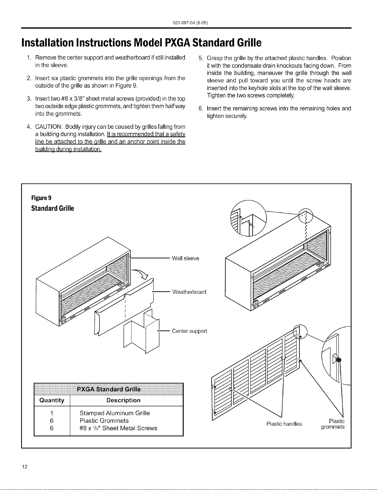
InstallationInstructionsModel PXGAStandardGrille
1. Removethe center support and weatherboard ifstill installed
in the sleeve.
2. Insert six plastic grommets into the grille openings from the
outside of the grille as shown in Figure 9.
3. Insert two #8 x 3/8" sheet metal screws (provided) in the top
two outside edge plasticgrommets,and tighten them halfway
intothe grommets.
4. CAUTION: Bodily injury can be caused bygrillesfalling from
a building during installation. It is recommended that a safety
line be attached to the grille and an anchor point inside the
buildina durina installation.
5. Grasp the grille by the attached plastic handles. Position
itwith the condensate drain knockouts facingdown. From
inside the building, maneuver the grille through the wall
sleeve and pull toward you until the screw heads are
inserted intothe keyhole slotsat the top of the wall sleeve.
Tighten the two screws completely.
6. Insert the remaining screws into the remaining holes and
tighten securely.
Figure9
Standard Grille
Wall sleeve
-- Weatherboard
-- Center support
Quantity Description
1 Stamped Aluminum Grille
6 Plastic Grommets
6 #8 x 3/8"Sheet Metal Screws
!
Plastichandles Plastic
grommets
12
920-087-04 (8-05)
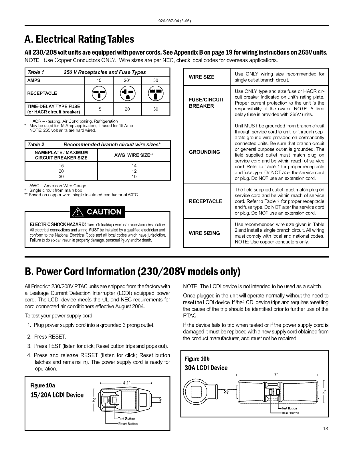
A. ElectricalRatingTables
All 230/208 voltunitsareequippedwithpowercords.SeeAppendixBonpage19 forwiringinstructionson265V units.
NOTE: Use Copper Conductors ONLY. Wire sizes are per NEC, check local codes for overseas applications.
Table 1 250 V Receptacles and Fuse Types
AMPS 15 20* 30
RECEPTACLE (_ @ @
TIME-DELAY TYPE FUSE
15 20 30
(or HACR circuit breaker)
HACR - Heating, Air Conditioning, Refrigeration
* May be used for 15Amp applications if fused for 15Amp
NOTE: 265 volt units are hard wired.
Table 2 Recommended branch circu# wire sizes*
NAMEPLATE / MAXIMUM
AWG WIRE SIZE**
CIRCUIT BREAKER SIZE
15 14
20 12
30 10
AWG -American Wire Gauge
* Single circuit from main box
** Based on copper wire, single insulated conductor at 60°C
ELECTRIC SHOCK HAZARD! rumdfelectricpowerbeforeserviceorinstallation.
AllelectricalconnectionsandwiringMUSTbeinstalledbyaqualifiedelectricianand
conformtothe NationalBectricatCode and alllocal codeswhichhavejurisdiction.
Failuretodoso canresultinpropertydamage,personalinjuryand/ordeath.
WIRE SIZE
FUSE/CIRCUIT
BREAKER
GROUNDING
RECEPTACLE
WIRE SIZING
Use ONLY wiring size recommended for
single outlet branch circuit.
Use ONLY type and size fuse or HACR cir-
cuit breaker indicated on unit's rating plate.
Proper current protection to the unit is the
responsibility of the owner. NOTE: A time
delay fuse is provided with 265V units.
Unit MUST be grounded from branch circuit
through service cord to unit, or through sep-
arate ground wire provided on permanently
connected units. Be sure that branch circuit
or general purpose outlet is grounded. The
field supplied outlet must match plug on
service cord and be within reach of service
cord. Refer to Table 1 for proper receptacle
and fuse type. Do NOT alter the service cord
or plug. Do NOT use an extension cord.
The field supplied outlet must match plug on
service cord and be within reach of service
cord. Refer to Table 1 for proper receptacle
and fuse type. Do NOT alter the service cord
or plug. Do NOT use an extension cord.
Use recommended wire size given in Table
2 and install a single branch circuit. All wiring
must comply with local and national codes.
NOTE: Use copper conductors only.
B.PowerCordInformation(230/208V modelsonly)
All Friedrich230/208V PTACunitsareshippedfrom thefactorywith
a Leakage Current Detection Interrupter(LCDI)equipped power
cord. The LCDI device meets the UL and NEC requirementsfor
cordconnectedair conditionerseffectiveAugust2004.
Totestyourpowersupply cord:
1. Plug powersupplycord intoa grounded3 prongoutlet.
2. PressRESET.
3. Press TEST (listenfor click; Resetbuttontripsand popsout).
4. Press and release RESET (listen for click; Reset button
latchesand remainsin).The power supply cord is readyfor
operation.
FigurelOa
15/20A I.CDI Device
2"
1
4 ,t ,i
NOTE: The LCDI device is not intended to be used as a switch.
Once pluggedin the unitwill operatenormallywithoutthe need to
resettheLCDIdevice.IftheLCDIdevicetripsandrequiresresetting
the cause of the tripshould be identified priorto furtheruse ofthe
PTAC.
If the devicefails to trip whentestedor ifthe powersupplycord is
damaged itmustbe replacedwith a newsupplycordobtainedfrom
the product manufacturer,and mustnot be repaired.
FigurelOb
30A I.CDI Device
13
920-087-04 (8-05)
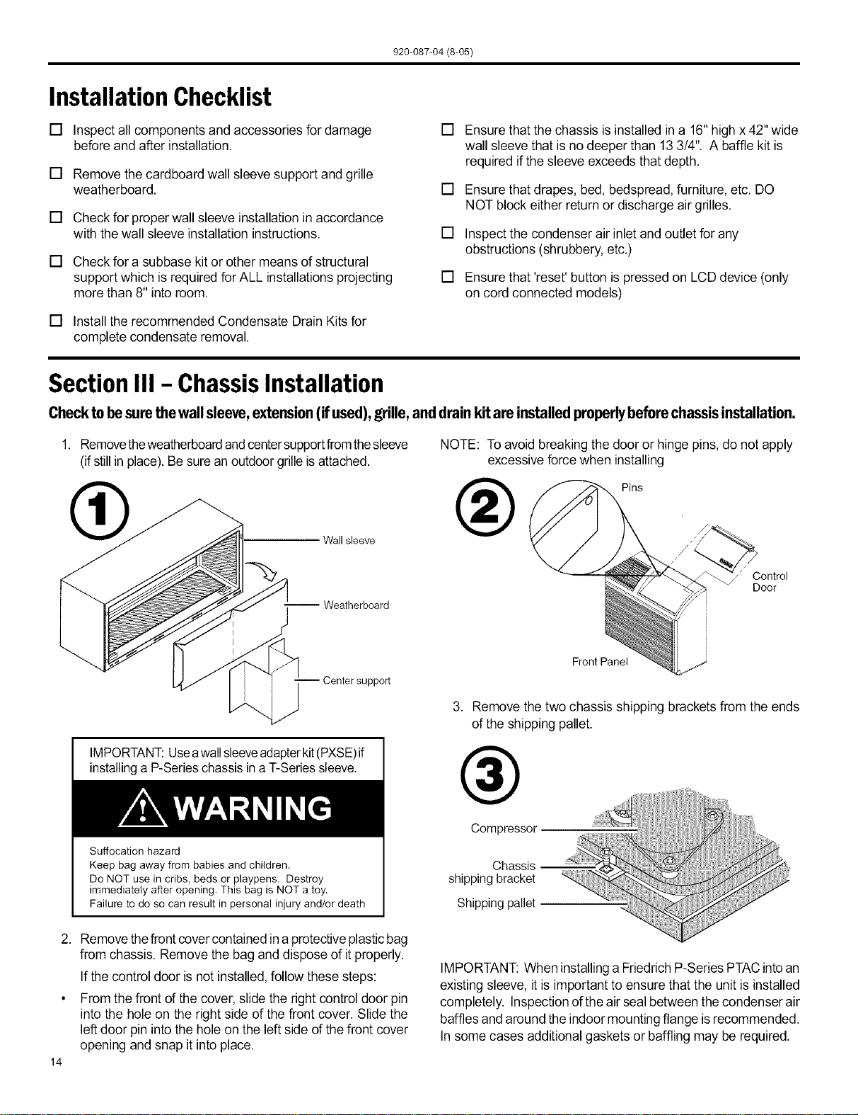
InstallationChecklist
[] Inspect all components and accessories for damage
before and after installation.
[] Remove the cardboard wall sleeve support and grille
weatherboard.
[] Check for proper wall sleeve installation in accordance
with thewall sleeve installation instructions.
[] Check for a subbase kit or other means of structural
support which is required for ALL installations projecting
more than 8" into room.
[] Installthe recommended Condensate Drain Kits for
complete condensate removal.
[] Ensure that the chassis is installed in a 16" high x 42"wide
wall sleeve that is no deeper than 13 3/4". A baffle kit is
required ifthe sleeve exceeds that depth.
[] Ensure that drapes, bed, bedspread, furniture, etc. DO
NOT block either returnor discharge air grilles.
[] Inspect the condenser air inlet andoutlet for any
obstructions (shrubbery, etc.)
[] Ensure that'reset' button is pressed on LCD device (only
on cord connected models)
Section III - ChassisInstallation
Checktobesurethewallsleeve,extension(ifused),grille,anddrainkitareinstalledproperlybeforechas.,isinstallation.
1. Removetheweatherboardand centersupportfromthesleeve
(ifstillin place).Besure an outdoorgrille isattached.
Wall sleeve
NOTE: Toavoid breaking the door or hinge pins, do not apply
excessive force when installing
®
Pins
--Weatherboard
Center support
IMPORTANT:Useawallsleeveadapterkit(PXSE)if
installinga P-Serieschassis ina T-Seriessleeve.
Suffocation hazard
Keep bag away from babies and children.
Do NOT use in cribs, beds or playpens. Destroy
immediately after opening. This bag is NOT a toy.
Failure to do so can result in personal injury and/or death
" Control
Door
i
J
Front Panel
3. Remove the two chassis shipping brackets from the ends
of the shipping pallet.
®
Compressor
Chassis
shipping bracket
Shipping pallet
2. Removethefront covercontained in a protectiveplasticbag
from chassis. Remove the bag anddispose of itproperly.
If the control door is not installed, follow these steps:
From the front of the cover, slide the right control door pin
into the hole on the right side of the front cover. Slide the
left door pin into the hole on the left side of the front cover
opening and snap it into place.
14
IMPORTANT: When installinga FriedrichP-Series PTAC intoan
existing sleeve, it is important to ensure that the unit is installed
completely. Inspection ofthe air seal between the condenser air
baffles and around the indoor mounting flange isrecommended.
In some cases additional gaskets or baffling may be required.
920-087-04 (8-05)
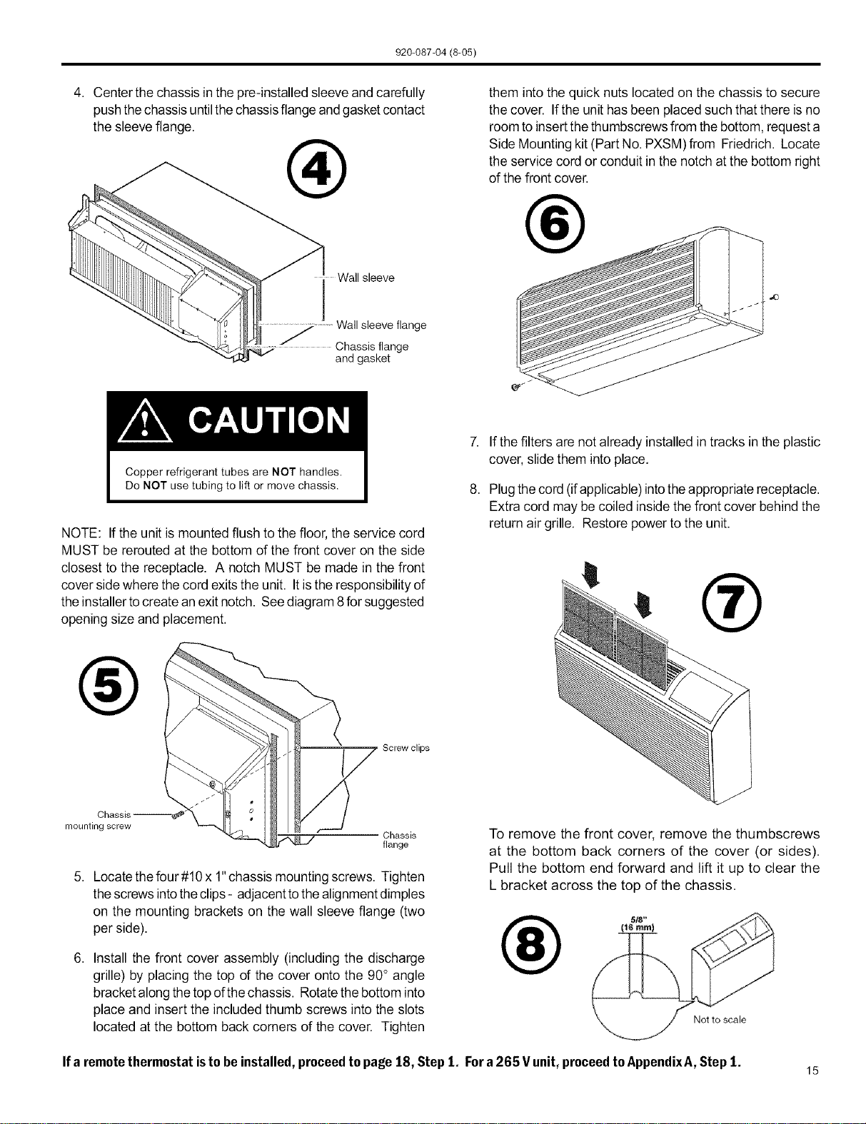
4. Center the chassis in the pre-installed sleeve and carefully
pushthe chassis untilthe chassisflange andgasket contact
the sleeve flange.
®
Wall sleeve
j Wall sleeve flange
Chassis flange
and gasket
them intothe quick nuts located on the chassis to secure
the cover. If the unit hasbeen placed such that there is no
room to insert thethumbscrews from the bottom, request a
Side Mounting kit (Part No. PXSM) from Friedrich. Locate
the service cord or conduit in the notch atthe bottom right
of the front cover.
®
7. Ifthe filters are not already installed in tracks in the plastic
cover, slidethem into place.
NOTE: If the unit ismounted flush to the floor, the service cord
MUST be rerouted at the bottom of the front cover on the side
closest to the receptacle. A notch MUST be made in the front
cover sidewhere thecord exitsthe unit. Itis the responsibility of
the installer tocreate anexit notch. See diagram8 for suggested
opening size and placement.
®
mounting screw
Screw clips
Chassis
flange
5. Locate the four#10 x 1"chassis mounting screws. Tighten
thescrews intotheclips - adjacentto thealignment dimples
on the mounting brackets on the wall sleeve flange (two
per side).
6. Install the front cover assembly (including the discharge
grille) by placing the top of the cover onto the 90° angle
bracketalong the topofthe chassis. Rotatethe bottom into
place and insert the included thumb screws into the slots
located at the bottom back corners of the cover. Tighten
8. Plugthecord (ifapplicable)into theappropriate receptacle.
Extra cord may be coiled inside the front cover behind the
return air grille. Restore power to the unit.
®
To remove the front cover, remove the thumbscrews
at the bottom back corners of the cover (or sides).
Pull the bottom end forward and lift it up to clear the
L bracket across the top of the chassis,
®
Not to scale
Ifa remotethermostatistobeinstalled, proceedto page 18, Step1, Fora 265 V unit,proceedto AppendixA,Step 1.
15
920-087-04 (8-05)
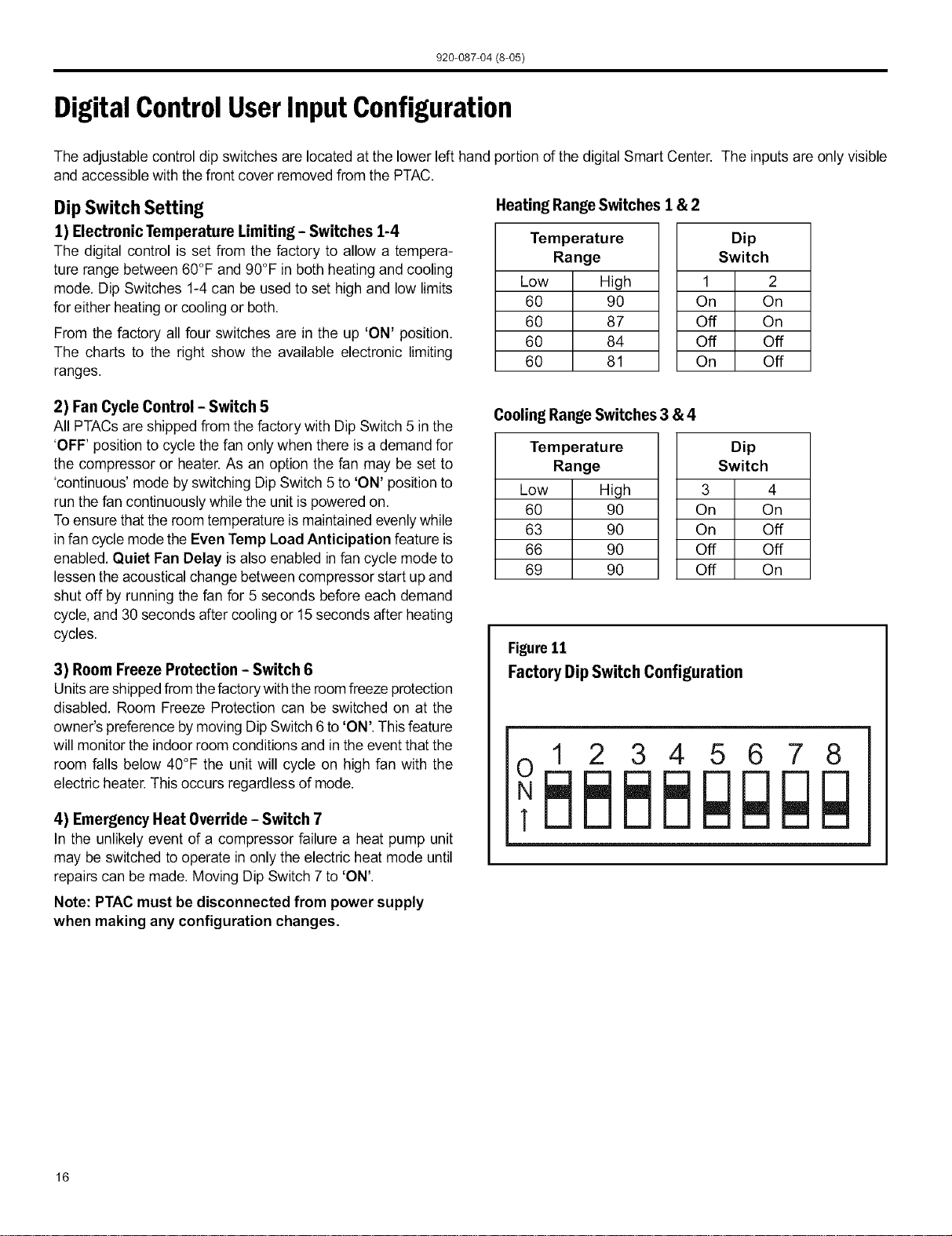
DigitalControlUserInputConfiguration
The adjustable control dipswitches are located at the lower left hand portion of the digital Smart Center. The inputs are only visible
and accessible with the front cover removed from the PTAC.
Dip Switch Setting
1) Electronic Temperature Limiting - Switches 1-4
The digital control is set from the factory to allow a tempera-
ture range between 60°F and 90°F in both heating and cooling
mode. Dip Switches 1-4can be used to set high and low limits
for either heating or cooling or both.
From the factory all four switches are in the up 'ON' position.
The charts to the right show the available electronic limiting
ranges.
Heating RangeSwitches 1 & 2
Temperature
Range
Low High
60 90
60 87
60 84
60 81
Dip
Switch
1 2
On On
Off On
Off Off
On Off
2) Fan Cycle Control - Switch 5
All PTACs are shipped from the factory with Dip Switch 5 in the
'OFF' position to cycle thefan only when there is a demand for
the compressor or heater. As an option the fan may be set to
'continuous' mode by switching Dip Switch 5 to 'ON' positionto
run the fan continuously while the unit is powered on.
Toensure that the room temperature is maintained evenlywhile
in fan cycle mode the Even Temp Load Anticipation feature is
enabled. Quiet Fan Belay isalso enabled in fan cycle mode to
lessen the acoustical change between compressor start up and
shut off by running the fan for 5 seconds before each demand
cycle, and 30 seconds after cooling or 15 seconds after heating
cycles.
3) Room Freeze Protection - Switch 6
Unitsare shippedfrom thefactorywith the roomfreeze protection
disabled. Room Freeze Protection can be switched on at the
owner's preference by moving Dip Switch 6 to 'ON'. This feature
will monitor the indoor room conditions and inthe event that the
room falls below 40°F the unit will cycle on high fan with the
electric heater. This occurs regardless of mode.
4) Emergency Heat Override - Switch 7
In the unlikely event of a compressor failure a heat pump unit
may be switched to operate in only the electric heat mode until
repairs can be made. Moving Dip Switch 7 to 'ON'.
Note: PTAC must be disconnected from power supply
when making any configuration changes.
CoolingRange Switches 3 & 4
Ternperatu re
Range
Low High
60 90
63 90
66 90
69 90
Dip
Switch
3 4
On On
On Off
Off Off
Off On
Figure11
Factory DipSwitch Configuration
12345678
16
920-087-04 (8-05)
DigitalControlOperation
TemperatureDisplay
The Ffiedfich digital PTAC isshipped from the factory to display
the desired room temperature on the LED readout.
The unit can be configured to display the room temperature by
simultaneously pressing the 'Cool' and 'High Fan' buttons
for three seconds the display will show an 'F,"for one seconds
to acknowledge the change. The unit will display the setpoint
whenever the 'Temp' A or v buttons are pressed and then
switch back to room temperature.
Torevertback todisplayingthe setpointonlypressthe'Ceor and
'LowFan' buttonsfor three seconds simultaneously,the unitwill
display an'S' for one seconds to acknowledge the change.
°Fvs. °C Display
The unit is factory configured to display all temperatures in
degrees Fahrenheit (°F). To switch to degrees Celsius press
the 'Fan Only' and 'Low Fan' buttons simultaneously for three
seconds. The display will show a 'C' as acknowledgement of
the change.
Torevert backto oFpress the 'Fan Only' and 'Low Fan' buttons
simultaneously forthree seconds. The display willshow an 'F' as
acknowledgement of the change.
CoolingMode
Pressingthe 'Cool' buttonwhile the unitisinany mode, including
off, will put the unit into cooling mode. Adjust the temperature
readout to the desired room temperature and the unit will cycle
the compressor on and off to maintain a comfortable room. The
compressor will come on anytime that the room temperature
is 1.8°F above the desired temperature. The fan operation is
dependentonthefan modeselected, eithercontinuousorcycling.
See page 16 for fan cycle control.
Heating Mode
Pressing the 'Heat' button while theunit isin anymode,including
off,will put the unit into heating mode.
Heat Pump Models (PDH)
When the 'Heat' button is pressed initially the unit will energize
the electric resistance heat to quickly bring the room to the
set temperature. When the desired room temperature falls
1.8°F below the desired set temperature the unit will cycle the
compressor onand operate asa heat pumpto maintain theroom
temperature while running more efficiently than resistance heat
only models. If the room temperature should fall more than 5°F
from the set temperature the unit will run the resistance heater.
Thefan operation isdependent on the fan mode selected,either
continuous or cycling. Dip switch 5 controls the fan mode, see
page 16 for setting.
Whenthe outdoorcoiltemperaturefalls below 30°Ffor morethan
2 minutesthe unitwill operate the resistance heaters and notthe
compressor. When the outdoor coil temperature reaches 45°F
the compressor will be allowed to operate again.
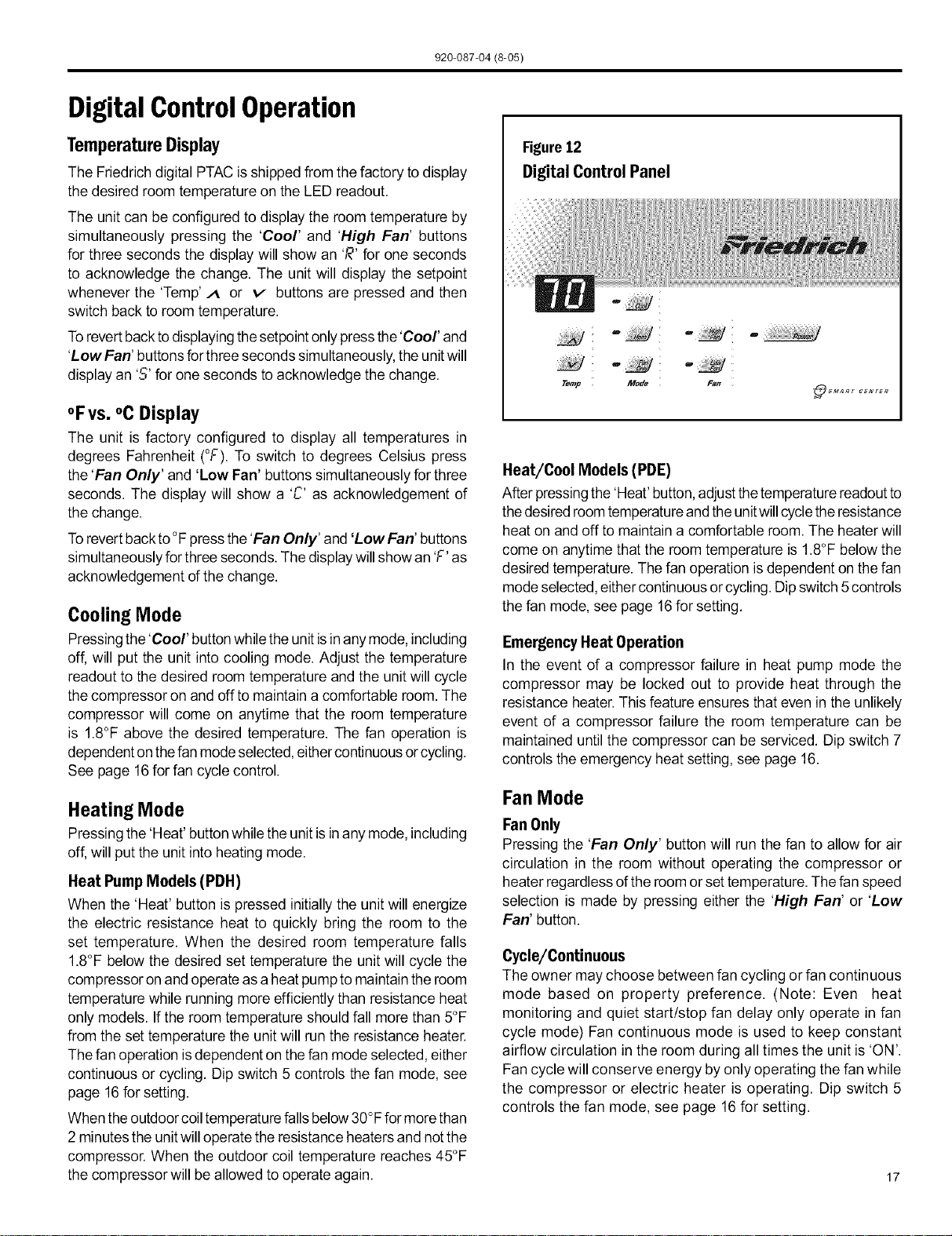
Figure12
DigitalControlPanel
Temp
Mode Fan
sMAnr CENTER
Heat/Cool Models (PDE)
After pressingthe 'Heat'button,adjust thetemperaturereadoutto
the desiredroomtemperatureand theunitwillcycletheresistance
heat on and off to maintain a comfortable room. The heater will
come on anytime that the room temperature is 1.8°F below the
desired temperature. Thefan operation is dependent on the fan
modeselected, eithercontinuous orcycling. Dipswitch 5 controls
the fan mode, see page 16for setting.
EmergencyHeat Operation
In the event of a compressor failure in heat pump mode the
compressor may be locked out to provide heat through the
resistance heater. This feature ensures that even in the unlikely
event of a compressor failure the room temperature can be
maintained until the compressor can be serviced. Dip switch 7
controls the emergency heat setting, see page 16.
Fan Mode
Fan Only
Pressing the 'Fan Only' button will run the fan to allow for air
circulation in the room without operating the compressor or
heater regardless ofthe room or set temperature. The fan speed
selection is made by pressing either the 'High Fan' or 'Low
Fan' button.
Cycle/Continuous
The owner may choose between fan cycling or fan continuous
mode based on property preference. (Note: Even heat
monitoring and quiet start/stop fan delay only operate in fan
cycle mode) Fan continuousmode is used to keep constant
airflow circulation in the room during alltimes the unit is 'ON'.
Fan cycle will conserve energy by only operating the fan while
the compressor or electric heater is operating. Dip switch 5
controls the fan mode, see page 16 for setting.
17
920-087-04 (8@5)
RemoteThermostatand LowVoltageControlConnections
Remote Thermostat
All Friedrich PD model PTAC units are factory configured to be
controlled byeither the chassis mounted Smart Center or a 24V
single stage remote wall mounted thermostat. The thermostat
may be auto or manual changeover as long as the control
configuration matches that of the PTAC unit.
To control the unit with a wall mounted thermostat follow
the steps below:
1) With thefront cover removed locatethelowvoltage terminal
strip at the lower portion of the Smart Center.
2) Remove thejumper between the 'GI2and GH' terminals.
3) The control is now configured for control bya wall thermo-
stat. The Smart Center will no longer control the unit.
4) If desired the accessory escutcheon kit (PDXRT) is to be
used, install itover the existing control panel.
Note:Torevert backtothe Smart Centercontrolofthe unitreplace
the jumper wire between the 'GI2and 'GH' terminals that was
removed in step 1.
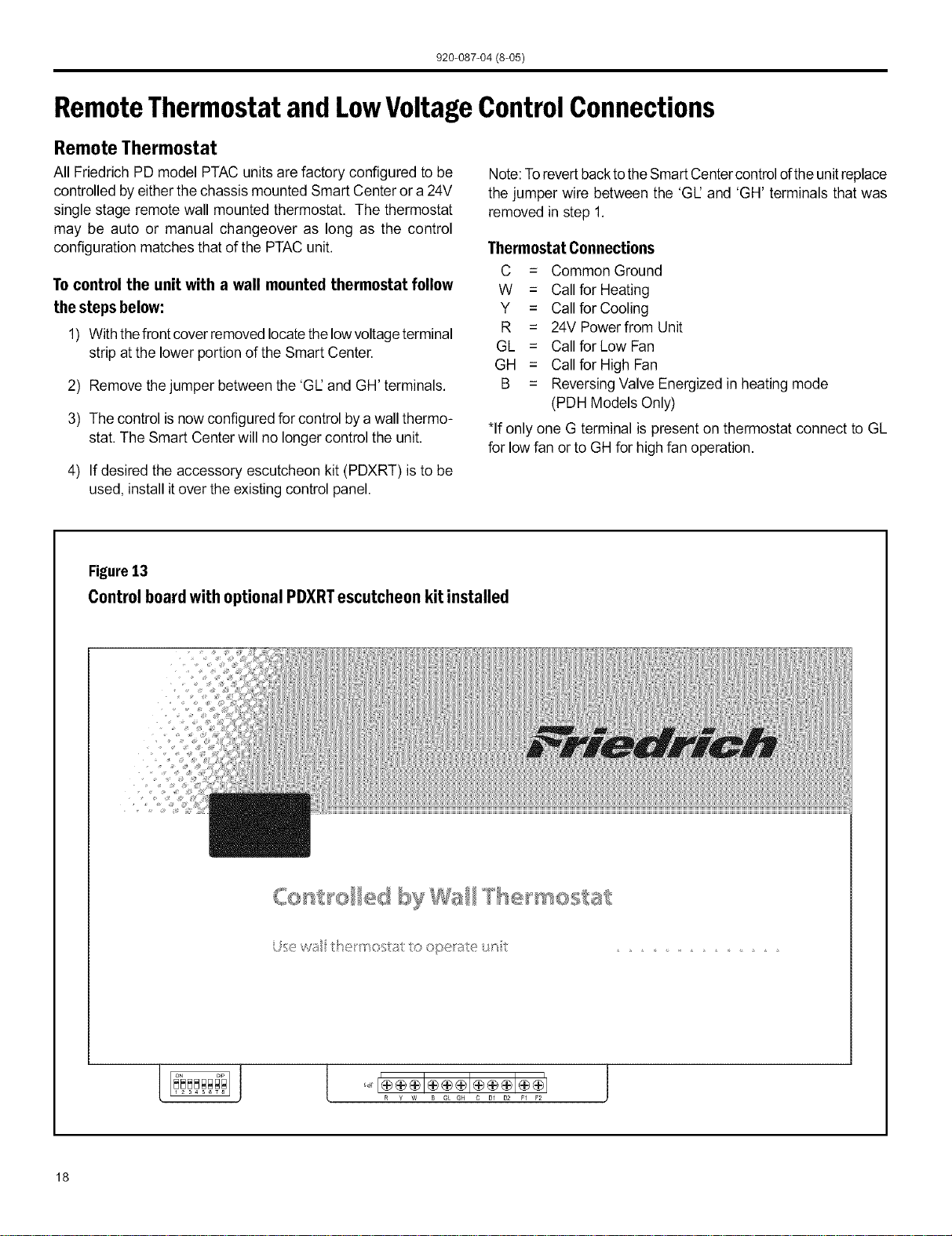
Thermostat Connections
C = Common Ground
W = Callfor Heating
Y = Callfor Cooling
R = 24V Powerfrom Unit
GL = Callfor Low Fan
GH = Callfor High Fan
B = Reversing Valve Energized in heating mode
(PDH Models Only)
*If only one G terminal is present on thermostat connect to GL
for lowfan or to GHfor high fan operation.
Figure13
Control board with optional PDXRTescutcheon kit installed
{oo st o byWa l ® mostat
U;sewu 1o operate _t
18
920-087-04 (8-05)
Desk ControlTerminals
The Friedrich PD model PTAC has built-in provisions for
connection to an external switch to control power tothe unit. The
switch can be a central desk control system or even a normally
open door switch.
For desk control operation connect one side of the switchto the
D1 terminal and the other to the D2 terminal (See figure 13).
Whenever the switch closes the unitoperation will stop.
Maximum Wire Length for Desk Control Switch
Wire Size
#24
#22
#2O
#18
#16
Maximum Length
400 ft.
6OOft.
9OOft.
1500 ft.
2000 ft.
Note: The desk
control system and
switches must be
field supplied.
Auxiliary Fan Control
The Smart Center also has the ability to control a 24VAC relay
to activate an auxiliary, or transfer, fan. The outputs are listed as
F1and F2on the control board.
To connect the relay,simply wire oneside of the relay to F1and
the othersideto F2.Anytime thatthe PTACfan runstheterminals
will send a 24VACsignal to the relay.The relay must be24 VAC,
50mA or less.
Note: The relay and auxiliary fans must befield supplied.
NOTE: It isthe installer's responsibility to ensure that all control
wiring connections are made in accordance with the installation
instructions. Improperconnection ofthethermostat control wiring
and/or tampering with the unit's internal wiring can void the
equipment warranty and may resultinproperty damage, personal
injury or death. Other manufacturer's PTACs and even older
Friedrich models may have different control wire connections.
Questions concerning proper connections to the unit should be
directed to the factory.
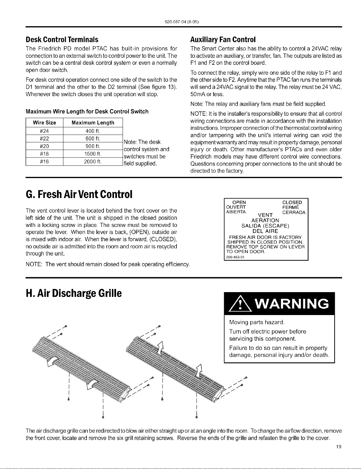
G.FreshAirVentControl
The vent control lever is located behind the front cover on the
left side of the unit. The unit is shipped in the closed position
with a locking screw in place. The screw must be removed to
operate the lever. When the lever is back, (OPEN), outside air
is mixed with indoor air. When the lever is forward, (CLOSED),
no outside air isadmitted into the room and room airis recycled
through the unit.
NOTE: The vent should remain closed for peak operating efficiency.
OPEN CLOSED
OUVERT FERME
ABIERTA CERRADA
VENT
AERATION
SALIDA (ESCAPE)
DEL AiRE
FRESH AIR DOOR IS FACTORY
SHIPPED IN CLOSED POSITION.
REMOVE TOP SCREW ON LEVER
TO OPEN DOOR.
250-453-01
H.Air DischargeGrille
Moving parts hazard,
Turn off electric power before
servicing this component.
Failure to do so can result in property
damage, personal injury and/or death.
Theair dischargegrille canbe redirectedto blowaireitherstraightup oratan angle intotheroom. Tochangethe airflowdirection,remove
thefront cover, locate and removethe six grill retainingscrews. Reversethe ends of the grilleand refasten the grille tothe cover.
19
920-087-04 (8-05)
I.Start-upChecklist
F! Inspect all components and accessories for
damage before and after installation.
[] Check installation for compliance with all national
and local codes and ordinances.
[] Read and follow all manufacturer's installation
instructions.
[] Check that circuit breaker(s) and electrical wire
sizes are correct. If the unit is supplied with a
power supply cord, insure that it is stored properly.
[] Check the condensate water drain outlet(s) to
make sure they are in compliance with all national
and local codes, that they are adequate for the
removal of condensate water, and that they meet
the approval of the end user.
[] Strictly follow installation instructions concerning
clearances around the unit,
[] Secure components and accessories, such as the
control door and front cover.
[] Check the unit air filter, condenser coil and
evaporator coil for any obstructions,
[]
[]
Check for proper operation of all components.
Instruct the owner or operator of the units
operation, and the manufacturer's
recommended routine maintenance schedule,
NOTE: It is highly recommended that a maintenance
schedule log book be prepared for recording
the dates and times of service.
[] Operate the unit for twenty minutes, Record
the unit's indoor/outdoor intake and discharge
temperatures, amperage draw, and power voltage.
[] Assemble the Warranty Certificate, the Operation
and Installation Manual, all accessory installation
instructions and the name, address and telephone
number of the Authorized Friedrich Warranty
Service Company in the area for the owner or
operator,
NOTE: Units are to be installed, inspected, and checked byqualified service personnel only.
20
920-087-04 (8-05)
AppendixA: ElectricalWiringfor265 VoltModels
NOTE: Itis recommended thatthe PXSB subbase assembly,the PXCJ conduit kitand the PXDS disconnect switch be installed on all
hardwired units. Ifinstalling aflush-floor mounted unit,make provisionsfor all the line voltage power leads andconduit to be removed
for ease of maintenance and service to the chassis.
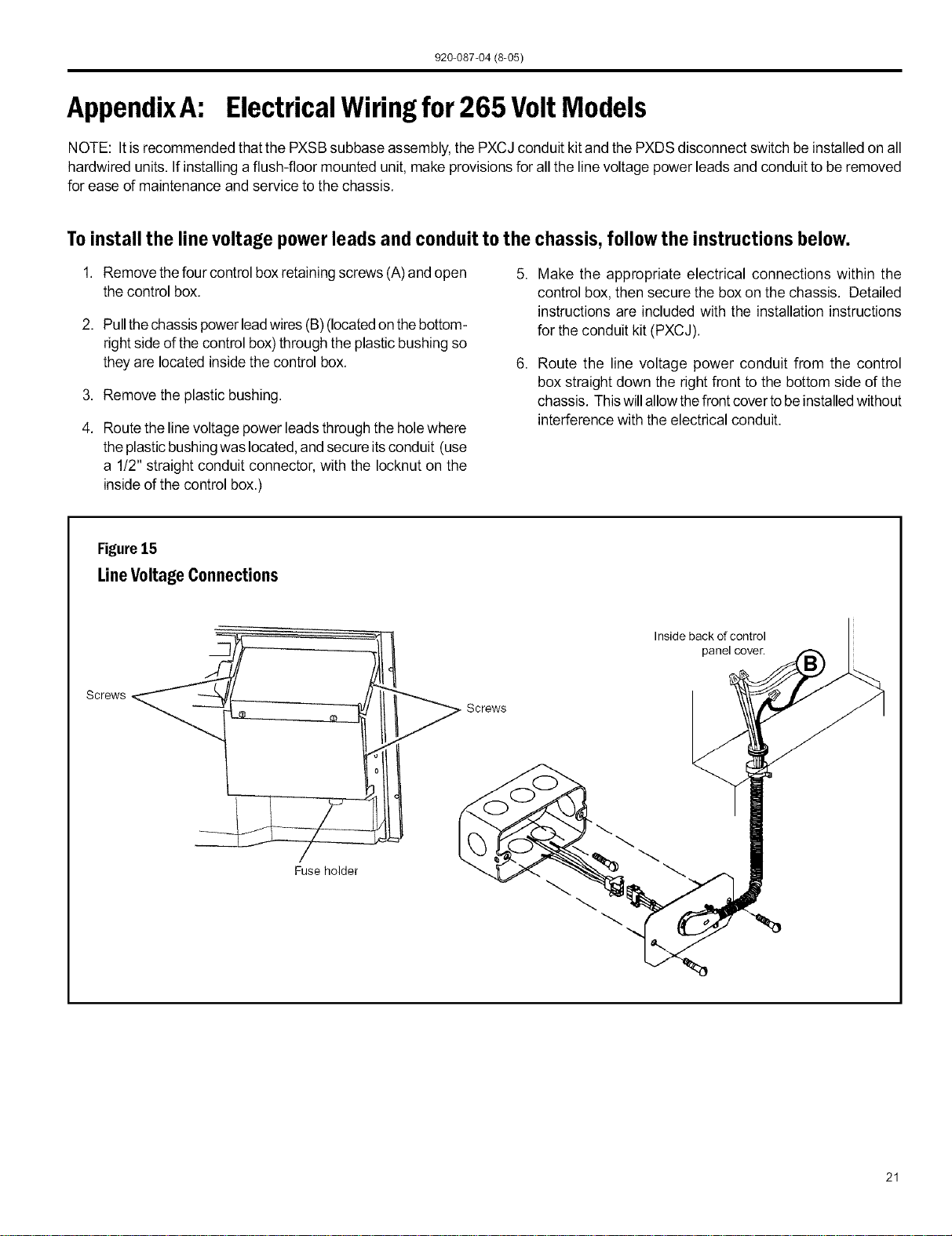
Toinstall the line voltage powerleads and conduit to the chassis, follow the instructions below.
1. Remove thefour control boxretainingscrews (A)and open
the control box.
2. Pull thechassispowerleadwires (B) (locatedonthebottom-
rightside of the control box)through the plasticbushing so
they are located insidethe control box.
3. Remove the plastic bushing.
4. Route the linevoltage power leads through the holewhere
the plasticbushingwas located,and secure itsconduit (use
a 1!2" straight conduit connector, with the Iocknut on the
insideof the control box.)
5. Make the appropriate electrical connections within the
control box, then secure the box on the chassis. Detailed
instructions are included with the installation instructions
for the conduit kit (PXCJ).
6. Route the line voltage power conduit from the control
box straight down the right front to the bottom side of the
chassis. Thiswillallow thefront cover tobeinstalledwithout
interference with the electrical conduit.
Figure15
LineVoltageConnections
Screws
Fuse holder
Screws
Inside back of control
panel cover.
21
920-087-04 (8-05)
J.RoutineMaintenance
NOTE: Units are to be inspected and serviced by qualified service personnel only.
1. Cleantheunitair intakefilter atleast every 300 to350 hours
of operation. Cleanthefilters with a milddetergent inwarm
water and allow to dry thoroughly before reinstalling.
2. The indoorcoil(evaporatorcoil),theoutdoorcoil(condenser
coil) and base pan should be inspected periodically (yearly
or bi-yearly)andcleaned ofalldebris(lint,dirt, leaves,paper,
etc.). Clean the coils and base pan with a soft brush and
compressed airor vacuum. Ifusing a pressure washer, be
careful notto bend thealuminium fin pack. Use asweeping
upand down motionin thedirectionofthevertical aluminum
fin pack when pressure cleaning coils. Cover all electrical
components to protect them fromwater orspray.
Before reinstalling the chassis in the sleeve, inspect the
indoor blowerhousing, blowerwheel, condenser fan blade,
and condenser shroud periodically (yearly or bi-yearly) and
clean of all debris (lint, dirt, mold, fungus, etc.) Clean the
blowerhousingarea and blowerwheel with an antibacterial
/ antifungal cleaner. Use a biodegradable cleaning agent
and degreaser on condenser fan and condenser shroud.
Use warm or cold water when rinsing these items. Allow
the unit to dry thoroughly, inspect all gasket material for
deterioration (replace as necessary), and then reinstall the
chassis in the sleeve.
,
,
Periodically (at least yearly or bi-yearly): inspect all control
components, both electricaland mechanical, aswell asthe
power supply. Use proper testing instruments (voltmeter,
ohmmeter, ammeter, wattmeter, etc.) to perform electrical
tests. Use an air conditioning or refrigeration thermometer
to check room, outdoor and coil operating temperatures.
Useaslingpsychrometertomeasurewet bulbtemperatures
indoors and outdoors.
Inspectthe surroundingarea (insideand outside)to ensure
that the units' clearances have not been compromised or
altered.
Inspect the sleeve and drain system periodically (at least
yearly or bi-yearly) and clean ofall obstructions and debris.
Clean both areas with an antibacterial and antifungal
cleaner. Rinse bothitemsthoroughlywithwater andensure
that the drain outlets are operating correctly. Check the
sealant around the sleeve and reseal areas as needed.
Clean the front cover when needed. Use a mild detergent.
Wash and rinse with warm water. Allow them to dry
thoroughly before reinstalling them in the chassis.
NOTE: Do not use a caustic coil cleaning agent on coils
or base pan. Use a biodegradable cleaning agent and
degreaser.
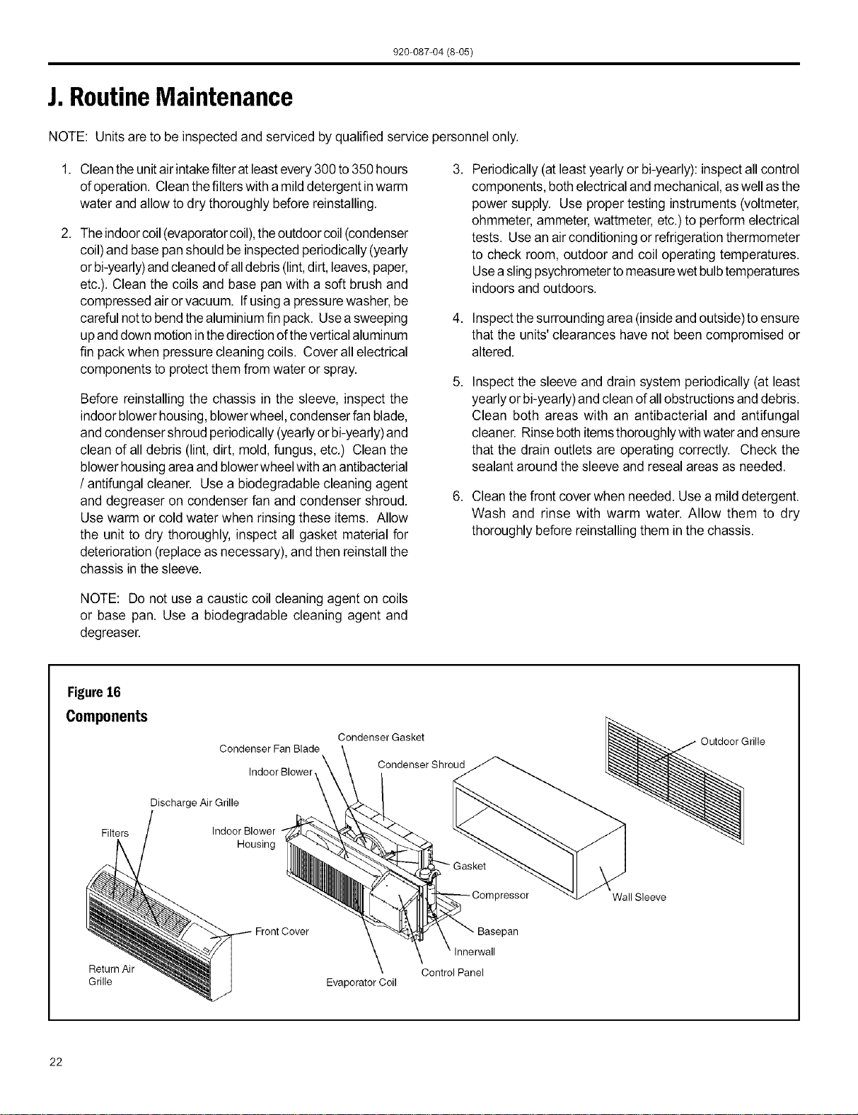
Figure16
Components
Filters
Condenser Fan Blade
Indoor Blower
Discharge Air Grille
Indoor Blower
Housing
Condenser Gasket
Condenser Shroud
Outdoor Grille
3ressor Wall Sleeve
Return Air Control Panel
Grille Evaporator Coil
22
920-087-04 (8-05)
K.BasicTroubleshootingTechniques
Being familiar with the sequence of operation on Standard Controlled Operating Units or the operation of the Remote Thermostat
Controlled Units is important. The following questions and answers may helpto identify performance problems.
EnvironmentalEffects- CoolingMode
Isunitsizedtoroomsizeareaand heatloaddemand?
The number of people in the room, numberof electrical devices,
solar gains, etc. are all variable items that can affect proper
sizing of the unit. Friedrich recommends that you consult with
an applications engineer for proper sizing.
Environmental Effects- Heating Mode
Isunitproperlysizedtoroomareaandheatloaddemand?
The number of peoplein the room, number of electrical devices,
solar gains, etc. are all variable items that can affect proper
sizing of the unit. Friedrich recommends that you consult with
an applications engineer for proper sizing.
Istheoutdoortemperature60°F orbelow?
The unit is designed for outdoor temperatures above 60°R
Isthe indoortemperature80°For above?
Ambient indoor temperatures of80°F or abovewill take a longer
period of run time to cool down the area. Long run times may
indicate that the unit isundersized.
Isindoorhumidityhigh?
This condition will cause the unit to operate longer to remove
humidity before noticing any cooling effect.
Hasthe heat loadbeen increasedbyadditional devicessuch
as computerequipment, orhasthe roomarea been increased
wherethe unitislocated?
If conditions havechanged, the unit maynot be able tocool and
condition as effectively as previously planned.
Istheoutdoortemperaturo70°For above?
The unit is designed for outdoor temperatures below 70°R
Is the indoor temperature 60°F or below? Ambient indoor
temperatures of 60°F or below will take a longer period of run
time to heat the area. Long run times may indicate that the unit
is undersized.
Hastheroomareabeenincreasedwherethe unitislocated?
If thearea where the unit islocated has been increased, the unit
may not provideadequate heat.
Insufficient Maintenance and Inspection
Installationerrorsarethemostcommoncauseofpoorperformance.
Pleasefollow installationinstructions carefully. If other problems
exist, see Maintenance and Inspection Troubleshooting Guide
below.
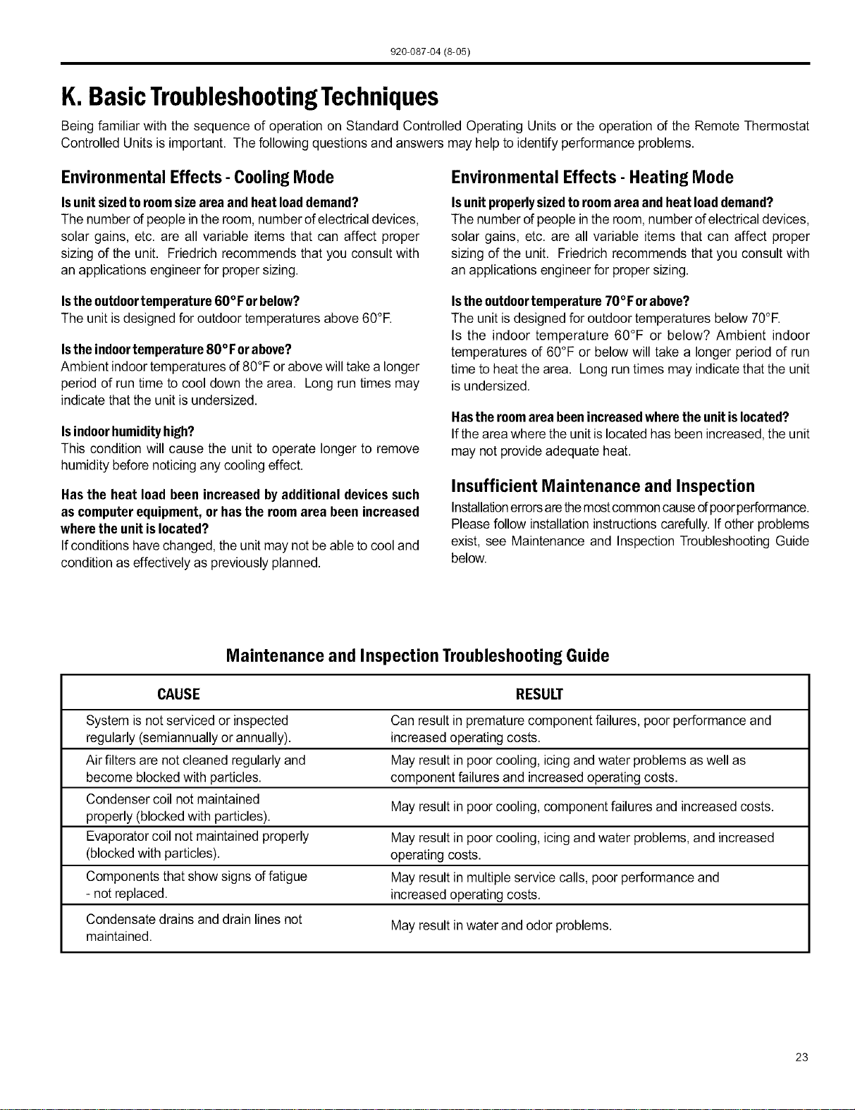
Maintenance and Inspection Troubleshooting Guide
CAUSE RESULT
System is not serviced or inspected Can result in premature component failures, poor performance and
regularly (semiannually or annually), increased operating costs.
Air filters are not cleaned regularly and May result in poor cooling, icing and water problems aswell as
become blocked with particles, component failures and increased operating costs.
Condenser coil not maintained
May result in poor cooling, component failures and increased costs.
properly (blocked with particles).
Evaporator coil not maintained properly May result in poor cooling, icing and water problems, and increased
(blocked with particles), operating costs.
Components that show signs of fatigue May result in multiple service calls, poor performance and
- not replaced, increased operating costs.
Condensate drains and drain lines not May result in water and odor problems.
maintained.
23
920-087-04 (8-05)
DigitalControlDiagnosticsandTestMode
Diagnostics
The Friedrich Smart Center continuously monitors the PTAC unit
operation and will store service codes if certain conditions are
witnessed. In some cases the unit may take action and shut the
unit off until conditions are corrected.
Toaccess theerror code menu press the 'Heat' and 'High Fan'
buttons simultaneously for three seconds. If error codes are
present they will be displayed. If multiple codes exist you can
toggle between messages using the temp A button. To clear
all codes press the temp v button for three seconds while in
the error code mode. To exit without changing codes press the
'Low Fan' button.
TestMode
For service and diagnostic use only, the built-in timers and
delays on the PTAC may be bypassed by pressing the 'Cool'
and 'Low Fan' buttons simultaneously for three seconds while
in any mode to enter the test mode. TEwill be displayed when
entering test mode, and DEwill be displayedwhen exiting. The
testmode willautomatically be exited 30 minutesafter entering it
or bypressing the 'Cool' and 'Low Fan' buttons simultaneously
for three seconds.
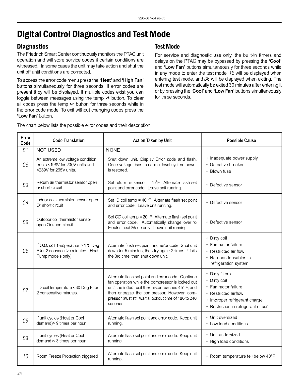
The chart below lists the possible error codes and their description:
Error
Code Translation Action Taken by Unit Possible Cause
Code
n., NOT USED NONE
UI
An extreme low voltage condition Shut down unit. Display Error code and flash. • Inadequate power supply
02 exists <198V for 230V units and Once voltage rises to normal level system power • Defective breaker
<239V for 265V units, isrestored. • Blown fuse
03 Return airthermistor sensor open Set return air sensor = 75°F. Alternate flash set • Defective sensor
or short circuit pointand error code. Leave unit running.
o,_I Indoorcoil thermistor sensor open Set ID coil temp = 40°F. Alternate flash set point • Defective sensor
Or short circuit and error code. Leave unit running.
Outdoor coil thermistor sensor SetOD coil temp =20°F. Alternate flash set point
n.g open Or short circuit and error code. Automatically change over to • Defective sensor
Electric heat Mode only. Leave unit running.
06
n"/
u/
IfO.D. coil Temperature > 175Deg
Ffor 2consecutive minutes. (Heat
Pump models only)
I.D coil temperature <30 Deg F for
2 consecutive minutes.
Alternate flash set point and error code. Shut unit
down for 5 minutes, then try again 2 times, if fails
the 3rd time, then shut down unit.
Alternate flash set point and error code. Continue
fan operation while the compressor is locked out
untilthe indoor coil thermistor reaches 45° F, and
then energize the compressor. However, com-
pressor must stillwait a lockout time of 180 to 240
seconds.
• Dirty coil
• Fan motor failure
• Restricted air flow
• Non-condensables in
refrigeration system
• Dirty filters
• Dirty coil
• Fan motor failure
• Restricted airflow
• Improper refrigerant charge
• Restriction in refrigerant circuit
08 Ifunit cycles (Heat or Cool Alternate flash set pointanderror code. Keep unit • Unit oversized
demand)> 9 times per hour running. • Low load conditions
nS, Ifunit cycles (Heat or Cool Alternate flash set pointanderror code. Keep unit • Unit undersized
demand)< 3 times per hour running. • High load conditions
Alternate flash set point and error code. Keep unit • Room temperature fell below 40°F
.,n Room Freeze Protection triggered
u running.
24
920-087-04 (8-05)
FriedrichPTACAccessories
MODELNUMBER DESCRIPTION PHOTO
PDXWS
PXGA
PXAA
PXDB
PXSC
PXDR10
PXWE
PXSB
RT2
PDXRT
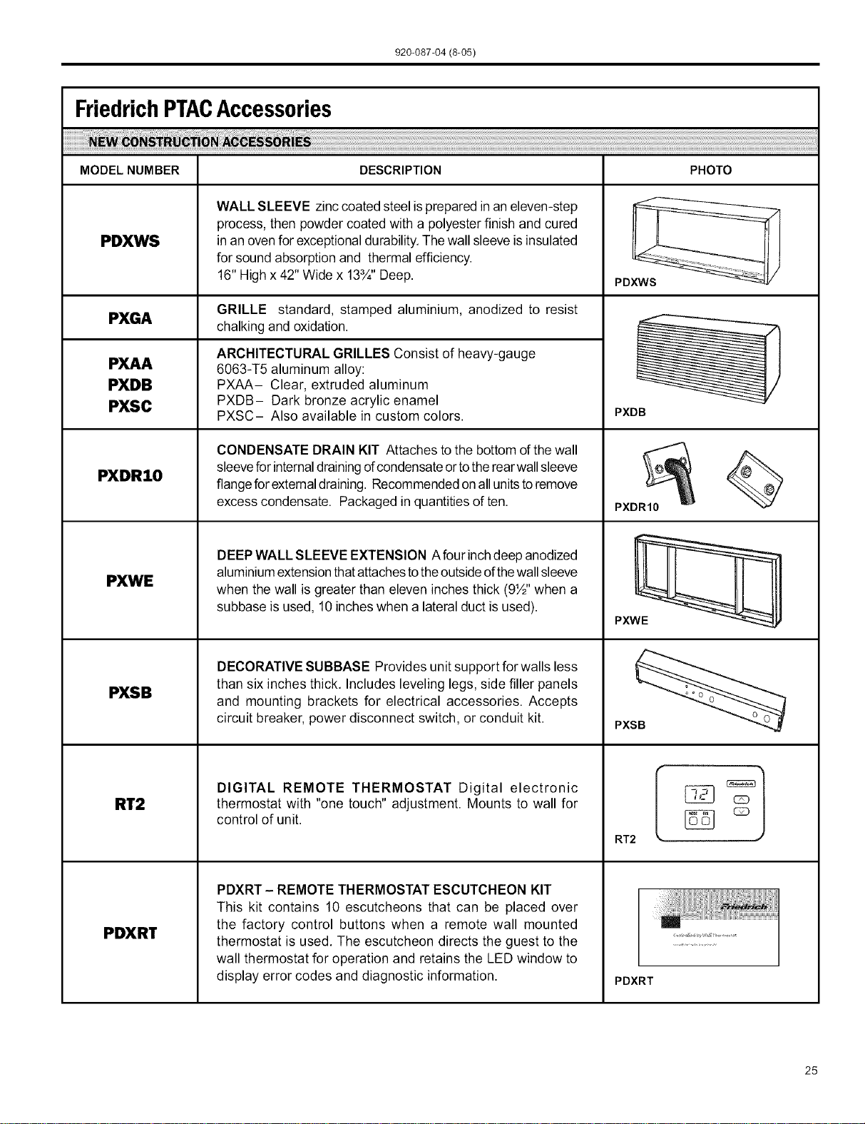
WALL SLEEVE zinc coated steel isprepared in an eleven-step
process, then powder coated with a polyester finish and cured
in an ovenfor exceptional durability. Thewall sleeve isinsulated
for sound absorption and thermal efficiency.
16" High x 42" Wide x 13¾" Deep.
GRILLE standard, stamped aluminium, anodized to resist
chalking and oxidation.
ARCHITECTURAL GRILLES Consist of heavy-gauge
6063-T5 aluminum alloy:
PXAA- Clear, extruded aluminum
PXDB- Dark bronze acrylic enamel
PXSC- Also available in custom colors.
CONDENSATE DRAIN KIT Attaches tothe bottom ofthe wall
sleeveforinternaldrainingofcondensateortothe rearwallsleeve
flangefor externaldraining. Recommendedon allunits toremove
excess condensate. Packaged inquantities of ten.
DEEPWALL SLEEVE EXTENSION Afour inchdeep anodized
aluminiumextensionthatattachestothe outsideofthewallsleeve
when the wall is greater than eleven inches thick (9½" when a
subbase is used, 10 inches when a lateral duct isused).
DECORATIVE SUBBASE Provides unit support for walls less
than six inches thick. Includes leveling legs, side filler panels
and mounting brackets for electrical accessories. Accepts
circuit breaker, power disconnect switch, or conduit kit.
DIGITAL REMOTE THERMOSTAT Digital electronic
thermostat with "one touch" adjustment. Mounts to wall for
control of unit.
PDXRT - REMOTE THERMOSTAT ESCUTCHEON KIT
This kit contains 10 escutcheons that can be placed over
the factory control buttons when a remote wall mounted
thermostat is used. The escutcheon directs the guest to the
wall thermostat for operation and retains the LED window to
display error codes and diagnostic information.
PDXWS
PXDB
PXDR10
PXWE
PXS_
RT2
PDXRT
25
920-087-04 (8-05)
MODELNUMBER DESCRIPTION PHOTO
PXSE
PDXDA
PDXDE
PXDL
PDXFT
PXCJ
PXPC
15/2o/3o
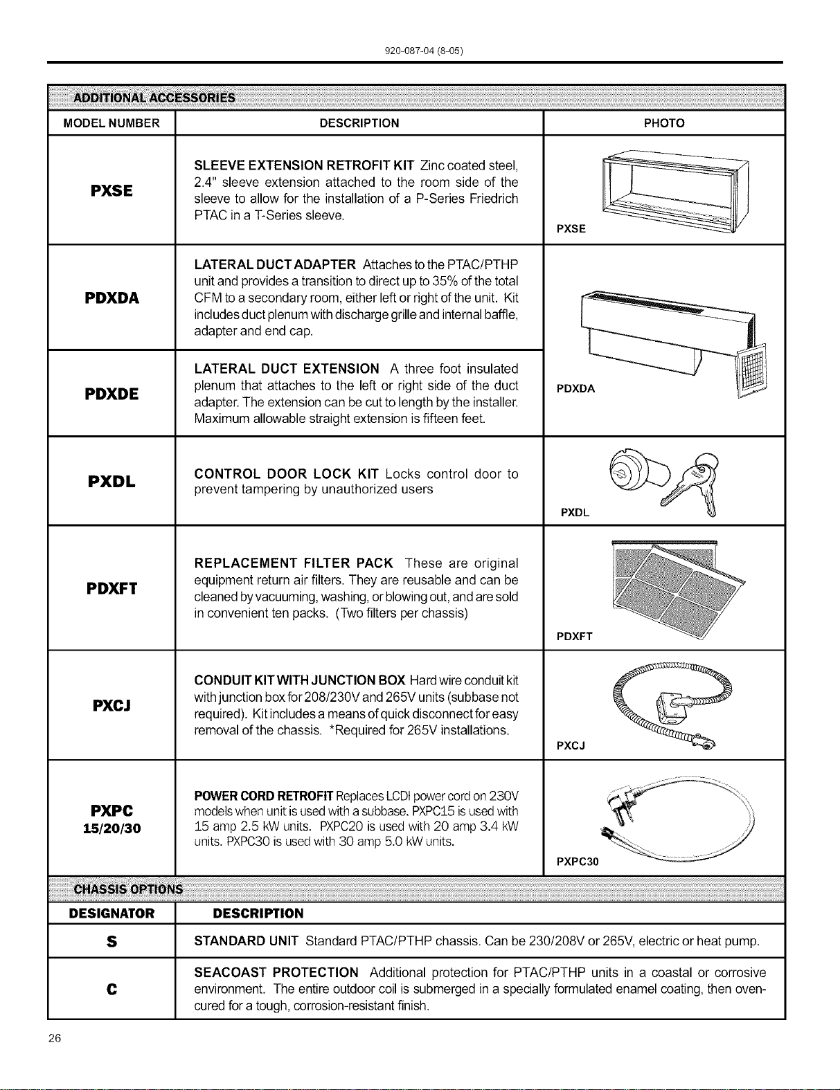
SLEEVE EXTENSION RETROFIT KIT Zinc coated steel,
2.4" sleeve extension attached to the room side of the
sleeve to allow for the installation of a P-Series Friedrich
PTAC in a T-Series sleeve.
LATERAL DUCTADAPTER Attaches tothe PTAC/PTHP
unitand provides a transition to direct up to 35% of the total
CFM toa secondary room, either left or right ofthe unit. Kit
includesduct plenumwithdischarge grilleand internalbaffle,
adapter and end cap.
LATERAL DUCT EXTENSION A three foot insulated
plenum that attaches to the left or right side of the duct
adapter. The extension can be cut to length bythe installer.
Maximum allowable straight extension is fifteen feet.
CONTROL DOOR LOCK KIT Locks control door to
prevent tampering by unauthorized users
REPLACEMENT FILTER PACK These are original
equipment return air filters. They are reusable and can be
cleanedbyvacuuming,washing,or blowingout,andaresold
in convenient ten packs. (Two filters per chassis)
CONDUIT KITWITH JUNCTION BOX Hardwire conduitkit
with junction boxfor208/230V and 265V units(subbase not
required). Kitincludesa meansofquickdisconnectforeasy
removal ofthe chassis. *Required for 265V installations.
POWERCORDRETROFITReplacesLCDtpowercordon 230V
modelswhenunitisusedwith a subbase.PXPC15isusedwith
15 amp 2.5 kWunits. PXPC20isusedwith 20 amp 3.4 kW
units.PXPC30is usedwith 30 amp5.0 kWunits.
PXSE
PDXDA
PXDL
PDXFT
PXCJ
PXPC30
DESIGNATOR DESCRIPTION
S STANDARD UNIT Standard PTAC/PTHP chassis. Can be 230/208V or 265V, electric or heat pump.
SEACOAST PROTECTION Additional protection for PTAC/PTHP units in a coastal or corrosive
C environment. The entire outdoor coil is submerged in a speciallyformulated enamel coating, then oven-
curedfor a tough, corrosion-resistantfinish.
26
920-087-04 (8-05)
Friedrich Air Conditioning Company
P.O. Box 1540
San Antonio, TX 78295
210.357.4400
www.friedrich.com
PD-SERIES
PACKAGED TERMINAL AIR CONDITIONERS
LIMITED WARRANTY
SAVE THIS CERTIFICATE. Itgives you specific rights, you may also have other rights which may vary from state to state and province to
province.
In the event that your unit needs servicing, contact your nearest authorized service center. If you do not know the nearest service center,
ask the company that installed your unit or contact us - see address and telephone number above. When requesting service: please have
the model and serial number from your unit readily available.
Unless specified otherwise herein, the following applies: PACKAGED TERMINAL AIR CONDITIONERS AND HEAT PUMPS
LIMITED WARRANTY - FIRST YEAR (Eighteen (18) Months from the original date of purchase or twelve (12) months from
installation). Any defect in the unit's material or workmanship will be repaired or replaced free of charge by our authorized service center
during the normal working hours; and
LIMITED WARRANTY - SECOND THROUGH FIFTH YEAR (Sixty-six (66) months from the date of purchase) ON THE SEALED
REFRIGERATION SYSTEM. Any part of the sealed refrigeration system on the P-series that is defective in material or workmanship will be
repaired or replaced free of charge (excluding freight charges) by our authorized service center during normal working hours. The sealed
refrigeration system consists of the compressor, metering device, evaporator, condenser, reversing valve, check valve, and the
interconnecting tubing.
These warranties apply only while the unit remains at the original site and only to units installed inside the continental United
States, Alaska, Hawaii, Puerto Rico and Canada. The warranty applies only if the unit is installed and operated in accordance
with the printed instructions and in compliance with applicable local installation and building codes and good trade practices. For
international warranty information, contact the Friedrich Air Conditioning Company - International Division.
Reasonable proof must be presented to establish the original purchase date, otherwise the beginning date of this certificate will be
considered to be our shipment date plus sixty days. Replacement parts can be new or remanufactured. Replacement parts and labor are
only warranted for any unused portion of the unit's warranty.
We will not be responsible for and the user will pay for:
1. Service calls to:
A) Instruct on unit operation. B) Replace house fuses or correct house wiring. C) Clean or replace air filters. D) Remove
the unit from inaccessible locations. E) Correct improper installations.
2. Parts or labor provided by anyone other than an authorized service center.
3. Damage caused by:
A) Accident, abuse, negligence, misuse, riot, fire, flood, or acts of God. B) Operating the unit where there is a corrosive
atmosphere containing chlorine, fluorine, or any damaging chemicals (other than in a normal residential environment). C)
Unauthorized alteration or repair of the unit, which in turn affects its stability or performance. D) Failing to provide proper
maintenance and service. E) Using other than a "Seacoast Protected" unit in a coastal environment. F) Using an
incorrect power source. G) Faulty installation or application of the unit.
We shall not be liable for any incidental, consequential, or special damages or expenses in connection with any use or failure of
this unit. We have not made and do not make any representation or warranty of fitness for a particular use or purpose and there
is no implied condition of fitness for a particular use or purpose. We make no expressed warranties except as stated in this
certificate. No one is authorized to change this certificate or to create for us any other obligation or liability in connection with
this unit. Any implied warranties shall last for one year after the original purchase date. Some states and provinces do not allow
limitations on how long an implied warranty or condition lasts, so the above limitations or exclusions may not apply to you. The provisions of
this warranty are in addition to and net a modification of or subtraction from the statutory warranties and other rights and remedies provided
by law.
In case of any questions regarding the provisions of this warranty, the English version will govern.
(12-04)
27

FriedrichAir ConditioningCo.
PostOfficeBox 1540 •SanAntonio,Texas78295-1540
4200 N. PanAm Expressway• SanAntonio,Texas78218-5212
(210) 357-4400 • FAX (210) 357-4480
www.friedrich.com
Printed in the U,S,A. 920-087-04 (8-05)