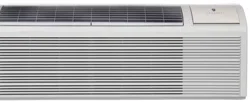
Installation and Operation Manual
Standard Chassis Models
Using R-32 Refrigerant
PVH12K3FC, PVH12R3FC
9K
12K
PVH09K3FC, PVH09R3FC
Freshaire
®
R-32 Series
PTAC
Packaged Terminal Air
Conditioners & Heat Pumps
THE EXPERTS IN ROOM AIR CONDITIONING

2
NOTE:
All PTAC 9000units come with a universal 2.5+1.0kW electric heater(standard 20A power cord for 3.5kW ,optional
15A power cord for 2.5kW). All PTAC 12000units come with a universal 3.5+1.5kW electric heater(standard 20A
power cord for 3.5kW,optional 30A power cord for 5kW,optional 15A power cord for 1.5kW).
Tableo f Contents
Congratulation s ·····································································································································
3
General
Instruction s ·······························································································································
3
Safety
precautions for R32 refrigerant·······································································································
6
General Specification s ···························································································································· 10
PTA
C
Installatio
n Recommendation s ········································································································ 11
Wall Sleev e Installatio n Instruction s ( PDXWSEZ/PDXWSA) ········································································· 12
Alternat e Wall Installations······················································································································· 13
PXDR1 0 Drai n Kit Installatio n Instruction s (optional fo r ne w construction ) ······················································1 6
External
Drai n (fo r ne w constructio n o r unit replacemen t) ·············································································1
7
PXG
A Standar d Grill e Installatio n Instruction s ·························································································· ·1 8
Chassi
s Install Preparatio n ······················································································································
2
2
Chassi
s Installation································································································································
·2
4
Friedric
h PTA C Digital Control an d Unit Feature s ·······················································································2 5
Syste
m Configuration····························································································································· ·2 7
Digital
Control Use r Inpu t Configuratio n ·····································································································2 8
Digital
Control Operatio n ························································································································· 3 0
Remo
te Control Thermosta t Installatio n ····································································································3 2
Remote Thermostat and Low Voltage Control Connections ·········································································
·3 2
Final
Inspectio n & Start-u p Checklist ········································································································3 4
Basi
c Troubleshooting···························································································································· · 35
Servic
e
& Assistanc e ······························································································································3 7
Accessories··········································································································································
·38
3
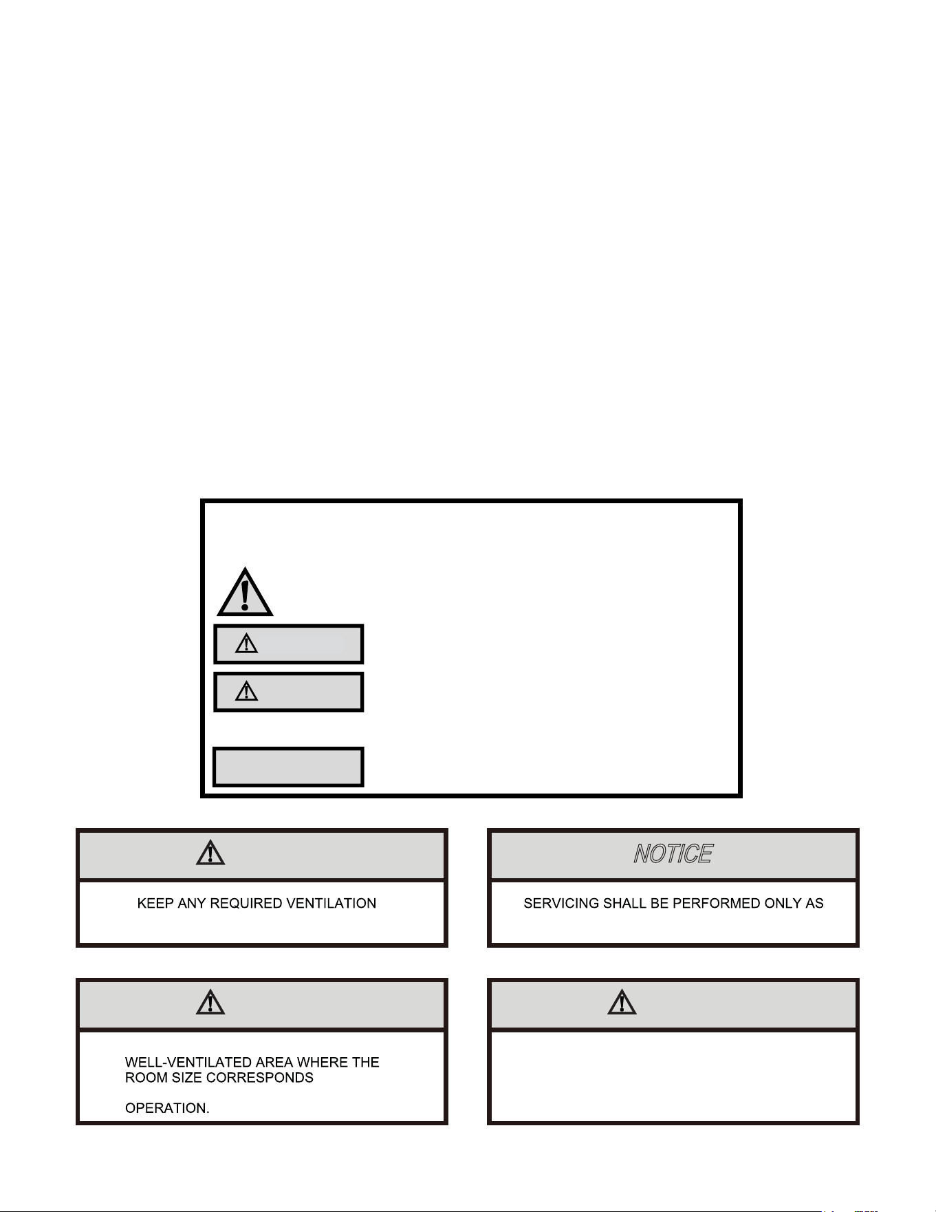
Your safety and the safety of others are very important.
We have provided many important safety messages in this manual and on your appliance. Always read and obey all
safety messages.
This is a safety Alert symbol.
This symbol alerts you to potential hazards that can kill or hurt you and others.
All safety messages will follow the safety alert symbol with the word “WARNING”
or “CAUTION”. These words mean:
WARNING
CAUTION
Indicates a hazard which, if not avoided, can result in severe personal injury or
death and damage to product or other property.
Indicates a hazard which, if not avoided, can result in personal injury and
damage to product or other property.
All safety messages will tell you what the potential hazard is, tell you how to reduce the chance of injury, and tell you
what will happen if the instructions are not followed.
NOTICE
Indicates property damage can occur if instructions are not followed.
Congratulations
Thank you for your decision to purchase Friedrich. Your new Friedrich has been carefully engineered and manufactured to give you many years of
dependable, efficient operation, maintaining a comfortable temperature and humidity level. Many extra features have been built into your unit to assure quiet
operation, the greatest circulation of cool, dry air, and the most economic operation.
General Instructions
The installation and servicing of this equipment must be performed by qualified, experienced technicians only. Professional installation personnel should have the
following experience:
• Installing the electric heater
• Opening of sealed components
• Opening of ventilated enclosures
• Commissioning and troubleshooting
• Checking the electric control part and wiring
• Breaking into the refrigerant circuit and charging
IMPORTANT NOTE TO THE OWNER
This manual is to be used by qualified, professionally trained HVAC technicians only. The manufacturer does not assume any responsibility for property damage
or personal injury for improper service procedures or services performed by an unqualified Person.
IMPORTANT NOTE TO THE SERVICER
Read this manual and familiarize yourself with the specific items which must be adhered to before attempting to service this unit. The precautions listed in this
Installation Manual are intended as supplemental to existing practices. However, if there is a direct conflict between existing practices and the content of this
manual, the precautions listed here take precedence.
WARNING
NOTICE
OPENINGS CLEAR OF OBSTRUCTION RECOMMENDED BY THE MANUFACTURER
WARNING WARNING
THE APPLIANCE SHALL BE STORED IN A
THE APPLIANCE SHALL BE STORED IN A ROOM
WITHOUT CONTINUOUSLY OPERATING OPEN
FLAMES (FOR EXAMPLE AN OPERATING GAS
APPLIANCE) AND IGNITION SOURCES (FOR
EXAMPLE AN OPERATING ELECTRIC HEATER)
TO THE ROOM AREA AS SPECIFIED FOR
NOTICE
INSTALLATION, SERVICE, MAINTENANCE AND
REPAIR OF THIS UNIT MUST BE PERFORMED BY A
CERTIFIED TECHNICIAN.
NOTICE
PRODUCT UNINSTALLATION AND RECYCLING
MUST BE PERFORMED BY A CERTIFIED
TECHNICIAN.
NOTICE
THIS APPLIANCE IS NOT INTENDED FOR USE BY
PERSONS (INCLUDING CHILDREN) WITH REDUCED
PHYSICAL, SENSORY OR MENTAL CAPABILITIES, OR
LACK OF EXPERIENCE AND KNOWLEDGE,
UNLESS THEY HAVE BEEN GIVEN SUPERVISION OR
INSTRUCTION CONCERNING USE OF
THE APPLIANCE BY A PERSON RESPONSIBLE FOR
THEIR SAFETY.
NOTICE
CHILDREN SHOULD BE SUPERVISED TO ENSURE
THAT THEY DO NOT PLAY WITH THE APPLIANCE.
NOTICE
IF THE SUPPLY CORD IS DAMAGED, IT MUST BE
REPLACED BY THE MANUFACTURER, ITS SERVICE
AGENT OR SIMILARLY QUALIFIED PERSONS IN
ORDER TO AVOID A HAZARD.
NOTICE
THE APPLIANCE SHALL BE INSTALLED IN
ACCORDANCE WITH NATIONAL WIRING
REGULATIONS.
THE FOLLOWING WARNINGS ARE VERY IMPORTANT FOR SAFETY.
PLEASE READ THEM CAREFULLY BEFORE INSTALLATION!
1. The air conditioner must be installed by certificated installer. It's forbidden to install by those amateur.
2. Please check whether there is grounding wire in the power supply system before installation. If not, installers should refuse installing and explain the safety
principle to users.
3. To avoid electric shock or even death, the socket or terminal blocks for power supply to the air conditioner (include 277V and 115V and 208~230V series and
the units that have LCDI power cord) must connect a Ground Fault Circuit Interrupter.
4. During installation, the wire connection must strictly follow the rule which is zero line and fire line of unit should be connected to the zero line and fire line in the
power system. The connection in reverse is forbidden. Please be sure the ground wire is firmly connected otherwise it is possible to result in the electrical shock or
death.
5. WARNING-Risk of fire. flammable refeigerant used. To be repaired only by trained service personnel. Do no puncture refrigerant tubing. (ATTENTION-Risque
d’ incendie. Réfrigérant inflammable utilisé. À réparer uniquement par le personnel de service tranined. Ne pas percer les tubes de réfrigérant. )
6. WARNING-Risk of fire. Dispose of properly in accordance with federal or local regulations. Flammable refrigerant used. (AVERTISSEMENT-Risque d’ incendie.
Éliminez correctement conformément aux réglementations fédérales ou locales. Réfrigérant inflammable utilisé. )
7. WARNING-Risk of fire. Flammable refrigerant used. Consult repair manual/owner’ s guide before attempting to service this product. All safety precautions must
be followed. (AVERTISSEMENT-Risque d’ incendie. Réfrigérant inflammable utilisé. Consultez le manuel de réparation/le guide du propriétaire avant d’ essayer d’
entretenir ce produit. Toutes les précautions de sécurité doivent être SUIVIES. )
8. WARNING-Risk of fire due to flammable refrigerant used. Follow handling instructions carefully in compliance with national regulations. (ATTENTION-Risque d’
incendie dû à l’ utilisation d’ un fluide frigorigène inflammable. suivre attentivement les instructions de manipulation conformément aux réglementations
nationales. )
9. the minimum CLEARANCE from the appliance to combustible surfaces: 1.18".(le dégagement minimum entre l'appareil et les surfaces combustibles : 1.18")
4
NOTICE
THE SUPPLY VOLTAGE FLUCTUATION SHOULD BE
IN THE RANGE OF ±10% OF THE RATED VOLTAGE.
RECOGNIZE THIS SYMBOL AS A SAFETY PRECAUTION
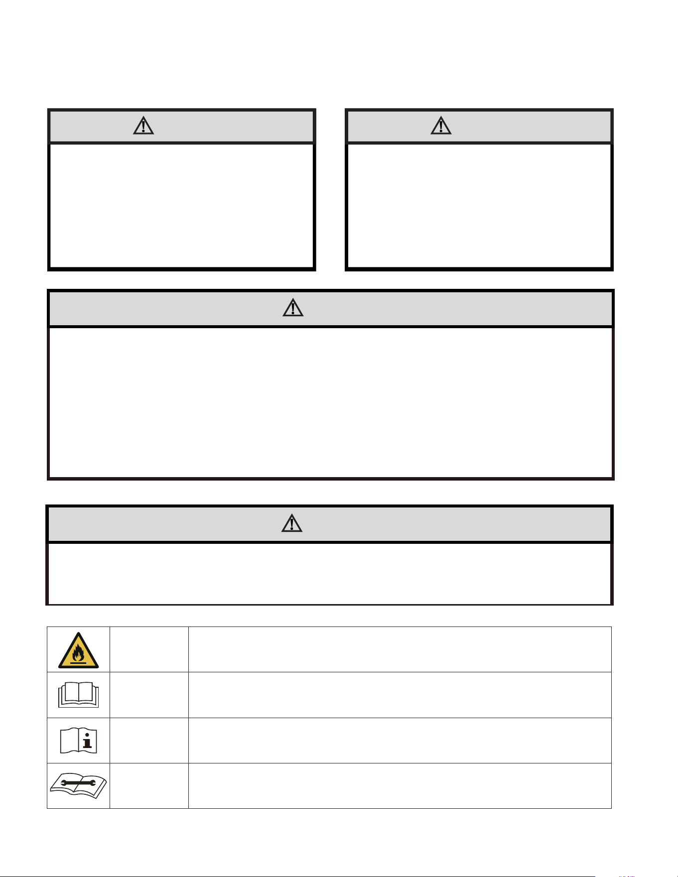
WARNING
THE MANUFACTURER WILL NOT BE RESPONSIBLE
FOR ANY INJURY OR PROPERTY, DAMAGE
ARISING FROM IMPROPER SERVICE OR SERVICE
PROCEDURES. IF YOU INSTALL OR PERFORM
SERVICE ON THIS UNIT, YOU ASSUME
RESPONSIBILITY FOR ANY PERSONAL INJURY OR
PROPERTY DAMAGE WHICH MAY RESULT, MANY
JURISDICTIONS REQUIRE A LICENSE TO INSTALL
OR SERVICE HEATING AND AIR CONDITIONING
EQUIPMENT.
WARNING
HIGH VOLTAGE
DISCONNECT ALL POWER BEFORE SERVICING OR
INSTALLING THIS UNIT. MULTIPLE POWER
SOURCES MAY BE PRESENT, FAILURE TO DO SO
MAY CAUSE PROPERTY DAMAGE, PERSONAL
INJURY OR DEATH.
WARNING
• DO NOT USE MEANS TO ACCELERATE THE DEFROSTING PROCESS OR TO CLEAN, OTHER THAN THOS
RECOMMENDED BY THE MANUFACTURER. (N’ UTILISEZ PAS DE MOYENS POUR ACCÉLÉRER LE PROCESSUS
DE DÉCONGÉLATION OU POUR NETTOYER, AUTRES QUE CEUX RECOMMANDÉS PAR LE FABRICANT. )
• THE APPLIANCE SHALL BE STORED IN A ROOM WITHOUT CONTINUOUSLY OPERATING IGNITION SOURCE
(FOR EXAMPLE: OPEN FLAMES, AN OPERATING GAS APPLIANCE OR AN OPERATING ELECTRIC HEATER. ) (L’
APPAREIL DOIT ÊTRE ENTREPOSÉ DANS UN LOCAL SANS SOURCES D’ INFLAMMATION FONCTIONNANT EN
CONTINU (PAR EXEMPLE: FLAMMES NUES, APPAREIL À GAZ EN FONCTIONNEMENT OU CHAUFFAGE ÉLECTR
IQUE EN FONCTIONNEMENT). )
• DO NOT PIERCE OR BURN. (NE PERCEZ PAS ET NE BRÛLEZ PAS.
• BE AWARE THAT REFRIGERANTS MAY NOT CONTAIN AN ODOUR. (SACHEZ QUE LES FRIGORIGÈNES PEUVEN
NE PAS CONTENIR D’ODEUR. )
WARNING
RISK OF FIRE, FLAMMABLE REFRIGERANT USED. TO BE REPAIRED ONLY BY TRAINED SERVICE PERSONNEL,
DO NOT PUNCTURE REFRIGERANT TUBING, DISPOSE OF PROPERLY IN ACCORDANCE WITH FEDERAL OR
LOCAL REGULATIONS.
5
THIS SYMBOL THAT THIS APPLIANCE USED A FLAMMABLE REFRIGER-
ANT. IF THE REFRIGERANT IS LEAKED AND EXPOSED TO AN EXTERNAL
IGNITION SOURCE, THERE IS A RISK OF FIRE.
WARNING
CAUTION
THIS SYMBOL THAT THE OPERATION MANUAL SHOULD BE READ CARE-
FULLY.
CAUTION
THIS SYMBOL THAT A SERVICE PERSONNEL SHOULD BE HANDLING
THIS EQUIPMENT WITH REFERENCE TO THE INSTALLATION MANUAL.
CAUTION
THIS SYMBOL THAT INFORMATION IS AVAILABLE SUCH AS THE OPERAT-
ING MANUAL OR INSTALLATION MANUAL.

SAFETY PRECAUTIONS FOR R32 REFRIGERANT
• The interior of unit should be maintained by HVAC techs only.
• 1. Information on servicing
• 1.1 Checks to the area
• Prior to beginning work on systems containing FLAMMABLE REFRIGERANTS, safety checks are necessary to ensure that the risk o f
ignition is minimised. For repair to the REFRIGERATING SYSTEM.
• 1.2 Work procedure
• Work shall be undertaken under a controlled procedure so as to minimise the risk of a flammable gas or vapour being present w hile the
work is being performed.
• 1.3 General work area
• All maintenance staff and others working in the local area shall be instructed on the nature of work being carried out. W ork in confined
spaces shall be avoided.
• 1.4 Checking for presence of refrigerant
• The area shall be checked with an appropriate refrigerant detector prior to and during work, to ensure the technician is aware of poten-
tially toxic or flammable atmospheres. Ensure that the leak detection equipment being used is suitable for use with all applica ble refriger-
ants, i. e. non-sparking, adequately sealed or intrinsically safe.
• 1.5 Presence of fire extinguisher
• If any hot work is to be conducted on the refrigerating equipment or any associated parts, appropriate fire extinguishing equip ment shall
be available to hand. Have a dry powder or CO
2
fire extinguisher adjacent to the charging area.
• 1.6 No ignition sources
• No person carrying out work in relation to a REFRIGERA TING SYSTEM which involves exposing any pipe work shall use any sources
of ignition in such a manner that it may lead to the risk of fire or explosion. All possible ignition sources, inc luding cigarette smoking,
should be kept suf ficiently far away from the site of installation, repairing, removing and disposal, during which refrigerant can possibly be
released to the surrounding space. Prior to work taking place, the area around the equipment is to be surveyed to make sure tha t there
are no flammable hazards or ignition risks. “No Smoking” signs shall be displayed.
• 1.7 Ventilated area
• Ensure that the area is in the open or that it is adequately ventilated before breaking into the system or conducting any hot work. A
degree of ventilation shall continue during the period that the work is carried out. The ventilation should safely disperse any release d
refrigerant and preferably expel it externally into the atmosphere.
• 1.8 Checks to the refrigerating equipment
• Where electrical components are being changed, they shall be fit for the purpose and to the correct specification. At all times the manu -
facturer’s maintenance and service guidelines shall be followed. If in doubt, consult the manufacturer’s technical department for assis-
tance.
• The following checks shall be applied to installations using FLAMMABLE REFRIGERANTS: the actual REFRIGERANT CHARGE is in
accordance with the room size within which the refrigerant containing parts are installed;
• the ventilation machinery and outlets are operating adequately and are not obstructed;
• if an indirect refrigerating circuit is being used, the secondary circuit shall be checked for the presence of refrigerant;
• marking to the equipment continues to be visible and legible. Markings and signs that are illegible shall be corrected;
• refrigerating pipe or components are installed in a position where they are unlikely to be exposed to any substance which may cor rode
refrigerant containing components, unless the components are constructed of materials which a re inherently resistant to being corroded or
are suitably protected against being so corroded.
• 1.9 Checks to electrical devices
• Repair and maintenance to electrical components shall include initial safety checks and component inspection procedures. If a faul t
exists that could compromise safety, then no electrical supply shall be connected to the circuit until it is satisfactorily dealt with. If the fault
cannot be corrected immediately but it is necessary to continue operation, an adequate temporary solution shall be used. This shall be
reported to the owner of the equipment so all parties are advised. Initial safety checks shall include:
• that capacitors are discharged: this shall be done in a safe manner to avoid possibility of sparking;
• that no live electrical components and wiring are exposed while charging, recovering or purging the system;
• that there is continuity of earth bonding.
6

• 2. Repairs to sealed components
• 2.1 During repairs to sealed components, all electrical supplies shall be disconnected from the equipment being worked upon prior to
any removal of sealed covers, etc. If it is absolutely necessary to have an electrical supply to equipment during servicing, then a perma-
nently operating form of leak detection shall be located at the most critical point to warn of a potentially hazardous situation.
• 2.2 Particular attention shall be paid to the following to ensure that by working on electrical components, the casing is not altered in
such a way that the level of protection is affected. This shall include damage to cables, excessive number of connections, terminals not
made to original specification, damage to seals, incorrect fitting of glands, etc.
• Ensure that the apparatus is mounted securely.
• Ensure that seals or sealing materials have not degraded to the point that they no longer serve the purpose of preventing the ingress of
flammable atmospheres. Replacement parts shall be in accordance with the manufacturer’s specifications.
• 3. Repair to intrinsically safe components
• Do not apply any permanent inductive or capacitance loads to the circuit without ensuring that this will not exceed the permissible volt-
age and current permitted for the equipment in use.
• Intrinsically safe components are the only types that can be worked on while live in the presence of a flammable atmosphere. The test
apparatus shall be at the correct rating.
• Replace components only with parts specified by the manufacturer. Other parts may result in the ignition of refrigerant in the atmo-
sphere from a leak.
• NOTE: The use of silicon sealant can inhibit the effectiveness of some types of leak detection equipment. Intrinsically safe components
do not have to be isolated prior to working on them.
• 4. Cabling
• Check that cabling will not be subject to wear, corrosion, excessive pressure, vibration, sharp edges or any other adverse environmental
effects. The check shall also take into account the effects of aging or continual vibration from sources such as compressors or fans.
• 5. Detection of flammable refrigerants
• Under no circumstances shall potential sources of ignition be used in the searching for or detection of refrigerant leaks. A halide torch
(or any other detector using a naked flame) shall not be used.
• The following leak detection methods are deemed acceptable for all refrigerant systems. Electronic leak detectors may be used to
detect refrigerant leaks but, in the case of FLAMMABLE REFRIGERANTS, the sensitivity may not be adequate, or may need re-calibra-
tion. (Detection equipment shall be calibrated in a refrigerant-free area.) Ensure that the detector is not a potential source of ignition and is
suitable for the refrigerant used. Leak detection equipment shall be set at a percentage of the LFL of the refrigerant and shall be calibrated
to the refrigerant employed, and the appropriate percentage of gas (25 % maximum) is confirmed.
• Leak detection fluids are also suitable for use with most refrigerants but the use of detergents containing chlorine shall be avoided as
the chlorine may react with the refrigerant and corrode the copper pipe-work NOTE Examples of leak detection fluids are
• bubble method,
• fluorescent method agents.
• If a leak is suspected, all naked flames shall be removed/extinguished.
• If a leakage of refrigerant is found which requires brazing, all of the refrigerant shall be recovered from the system, or isolated (by
means of shut off valves) in a part of the system remote from the leak.
• 6. Removal and evacuation
• When breaking into the refrigerant circuit to make repairs – or for any other purpose – conventional procedures shall be used. However,
for flammable refrigerants it is important that best practice be followed, since flammability is a consideration. The following procedure shall
be adhered to:
• safely remove refrigerant following local and national regulations;
• purge the circuit with inert gas;
• evacuate (optional for A2L);
• purge with inert gas (optional for A2L);
• open the circuit by cutting or brazing.
7

• The refrigerant charge shall be recovered into the correct recovery cylinders if venting is not allowed by local and national codes. For
appliances containing flammable refrigerants, the system shall be purged with oxygen-free nitrogen to render the appliance safe for flam-
mable refrigerants. This process might need to be repeated several times.
• Compressed air or oxygen shall not be used for purging refrigerant systems. For appliances containing flammable refrigerants, refriger-
ants purging shall be achieved by breaking the vacuum in the system with oxygen-free nitrogen and continuing to fill until the working
pressure is achieved, then venting to atmosphere, and finally pulling down to a vacuum (optional for A2L). This process shall be repeated
until no refrigerant is within the system (optional for A2L). When the final oxygen-free nitrogen charge is used, the system shall be vented
down to atmospheric pressure to enable work to take place. Ensure that the outlet for the vacuum pump is not close to any potential igni-
tion sources and that ventilation is available.
• 7. Charging procedures
• In addition to conventional charging procedures, the following requirements shall be followed.
• Ensure that contamination of different refrigerants does not occur when using charging equipment. Hoses or lines shall be as short as
possible to minimise the amount of refrigerant contained in them.
• Cylinders shall be kept in an appropriate position according to the instructions.
• Ensure that the REFRIGERATING SYSTEM is earthed prior to charging the system with refrigerant.
• Label the system when charging is complete (if not already).
• Extreme care shall be taken not to overfill the REFRIGERATING SYSTEM.
• Prior to recharging the system, it shall be pressure-tested with the appropriate purging gas. The system shall be leak-tested on comple-
tion of charging but prior to commissioning. A follow up leak test shall be carried out prior to leaving the site.
• 8. Decommissioning
• Before carrying out this procedure, it is essential that the technician is completely familiar with the equipment and all its detail. It is
recommended good practice that all refrigerants are recovered safely. Prior to the task being carried out, an oil and refrigerant sample
shall be taken in case analysis is required prior to re-use of recovered refrigerant. It is essential that electrical power is available before the
task is commenced.
• Become familiar with the equipment and its operation.
• Isolate system electrically.
• Before attempting the procedure, ensure that:
▪ mechanical handling equipment is available, if required, for handling refrigerant cylinders;
▪ all personal protective equipment is available and being used correctly;
▪ the recovery process is supervised at all times by a competent person;
▪ recovery equipment and cylinders conform to the appropriate standards.
• Pump down refrigerant system, if possible.
• If a vacuum is not possible, make a manifold so that refrigerant can be removed from various parts of the system.
• Make sure that cylinder is situated on the scales before recovery takes place.
• Start the recovery machine and operate in accordance with instructions.
• Do not overfill cylinders (no more than 80% volume liquid charge).
• Do not exceed the maximum working pressure of the cylinder, even temporarily.
• When the cylinders have been filled correctly and the process completed, make sure that the cylinders and the equipment are removed
from site promptly and all isolation valves on the equipment are closed off.
• Recovered refrigerant shall not be charged into another REFRIGERATING SYSTEM unless it has been cleaned and checked.
• 9. Labelling
• Equipment shall be labelled stating that it has been de-commissioned and emptied of refrigerant. The label shall be dated and signed.
For appliances containing FLAMMABLE REFRIGERANTS, ensure that there are labels on the equipment stating the equipment contains
FLAMMABLE REFRIGERANT.
• 10. Recovery
• When removing refrigerant from a system, either for servicing or decommissioning, it is recommended good practice that all refrigerants
are removed safely.
• When transferring refrigerant into cylinders, ensure that only appropriate refrigerant recovery cylinders are employed. Ensure that the
correct number of cylinders for holding the total system charge is available. All cylinders to be used are designated for the recovered
refrigerant and labelled for that refrigerant (i. e. special cylinders for the recovery of refrigerant). Cylinders shall be complete with pres-
sure-relief valve and associated shut-off valves in good working order. Empty recovery cylinders are evacuated and, if possible, cooled
before recovery occurs. The recovery equipment shall be in good working order with a set of instructions concerning the equipment that is
at hand and shall be suitable for the recovery of all appropriate refrigerants including, when applicable, FLAMMABLE REFRIGERANTS. In
8

• addition, a set of calibrated weighing scales shall be available and in good working order. Hoses shall be complete with leak-free
disconnect couplings and in good condition. Before using the recovery machine, check that it is in satisfactory working order, has been
properly maintained and that any associated electrical components are sealed to prevent ignition in the event of a refrigerant release.
Consult manufacturer if in doubt.
• The recovered refrigerant shall be returned to the refrigerant supplier in the correct recovery cylinder, and the relevant waste transfer
note arranged. Do not mix refrigerants in recovery units and especially not in cylinders.
• If compressors or compressor oils are to be removed, ensure that they have been evacuated to an acceptable level to make certain that
FLAMMABLE REFRIGERANT does not remain within the lubricant. The evacuation process shall be carried out prior to returning the
compressor to the suppliers. Only electric heating to the compressor body shall be employed to accelerate this process. When oil is
drained from a system, it shall be carried out safely.
5. The sites for installing and maintaining an air conditioner using Refrigerant R32 should be free from open fire or welding, smoking,
drying oven or any other heat source higher than 548℃ which easily produces open fire.
6.. When installing an air condition , it is necessary to take appropriate anti-static measures such as wear anti-static clothing and/or
gloves.
7. It is necessary to choose the site convenient for installation or maintenance wherein the air inlets and outlets of the indoor and outdoor
units should be not surrounded by obstacles or close to any heat source or combustible and/or explosive environment.
8.. If the indoor unit s fers refrigerant leak during the installation, all the personnel should go out till the refrigerant leaks completely for 15
minutes. If the product is damaged, it is a must to carry such damaged product back to the maintenance station and it is prohibited to weld
the refrigerant pipe or conduct other operations on the user's site.
sofa and other valuables right under the lines on two sides of the indoor unit, and also prevent mechanical damage from occurring.
• 11. WARNING FOR USING R32 REFRIGERANT
• Appliance shall be installed, operated and stored in a room with a floor area larger than 4 m².
• Appliance shall not be installed in an unvertilated space, if that space is smaller than 4 m².
• Compliance with national gas regulations shall be observed.
• The appliance shall be stored so as to prevent mechanical damage from occurring.
• Any person who is involved with working on or breaking into a refrigerant circuit should hold a current valid certificate from an indus-
try-accredited assessment authority, which authorises their competence to handle refrigerants safely in accordance with an industry
recognised assessment specification.
• Servicing shall only be performed as recommended by the equipment manufacturer. Maintenance and repair requiring the assistance of
other skilled personnel shall be carried out under the supervision of the person competent in the use of flammable refrigerants.
• Please follow the instruction carefully to handle, install, clear, service the air conditioner to avoid any damage or hazard. Flammable
Refrigerant R32 is used within air conditioner. When maintaining or disposing the air conditioner, the refrigerant (R32) shall be recovered
properly, shall not discharge to air directly.
• No any open fire or device like switch which may generate spark/arcing shall be around air conditioner to avoid causing ignition of the
flammable refrigerant used.
• Please follow the instruction carefully to store or maintain the air conditioner to prevent mechanical damage from occurring.
• Flammable refrigerant -R32 is used in air conditioner. Please follow the instruction carefully to avoid any hazard.
• 12. Installation & Assembly Instructions
• Before installing the appliance, you must read the manual carefully to get the safety information and notes.
• Unit refrigerant charge amount: refer to unit name plate marking.
• A leak test must be done after the installation is completed.
• It is a must to do the safety inspection before maintaining or repairing an air conditioner using combustible refrigerant in order to ensure
that the fire risk is reduced to minimum.
• It is necessary to operate the machine under a controlled procedure in order to ensure that any risk arising from the combustible gas or
vapor during the operation is reduced to minimum.
9. It is necessary to choose the place where the inlet and outlet air of the indoor unit is eve
10. It is necessary to avoid the places where there are other electrical products, power switch plugs and sockets, kitchen cabinet, bed,
3
4
133.. Please note that:
1.. Handle gently.
2. At least two people needed to lift the chassis and prohibit lift the co pper pipes.
. Only trained or qualified people for installatio
. The installation site should be in a well-ventilated condition.
9
10
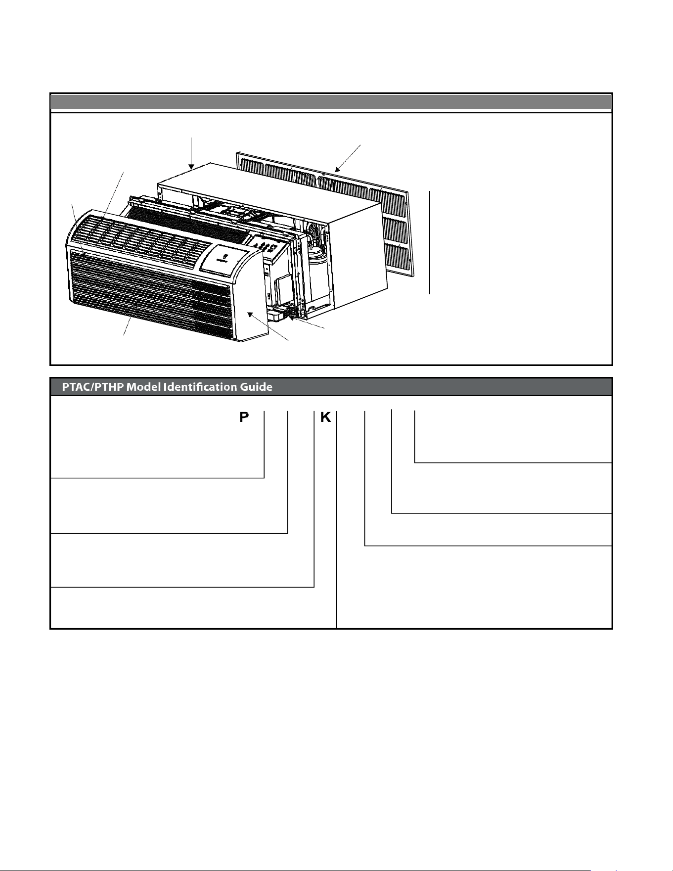
GeneralSpecifications
Typical Unit Components and Dimensions
WALL SLEEVE
DISCHARGE GRILLE
FILTERS
RETURN AIR GRILLE
OUTDOOR GRILLE
CHASSIS
FRONT COVER
PDXWS Wall Sleeve
Dimensions: 16" H x 42" W x
13-¾" D
Front Cover Dimensions:
16" H x 42" W x 7-¾" D
Cut-Out Dimensions:
16-¼" x 42-¼"
MODEL NUMBER
V
H
09
3 F
Series
PV = Friedrich Digital PTAC
System
E = Cooling with electric heat
H = Heat Pump with Auxiliary Heat
Nominal Capacity
Engineering Digit
Design Series
Chassis
F= FreshAire
07 = 7,000 Btuh
09 = 9,000 Btuh
Voltage
12 = 12,000 Btuh
15 = 15,000 Btuh
Nominal Heater Size (230V or 265V)
3=3kW
K = 230/208V - 1 Ph. - 60 Hz.
R = 265V - 1 Ph. - 60 Hz.
InstallationChecklist
. Inspect all components and accessories for damage before and
after installation.
. Remove the cardboard wall sleeve support and grill weatherboard.
. Check for proper wall sleeve installation in accordance with the wall
sleeve installation instructions.
. Check for a subbase kit or other means of structural support which
is required for ALL installations projecting more than 8" into room.
. Install the recommended Condensate Drain Kits for complete
condensate removal.
. Ensure that the chassis is installed in a 16" highx4'' wide wall sleeve
that is no deeper than 13-¾".A baffle kit is required if the sleeve
exceeds that depth.
. Ensure that chassis and chassis front cover are installed and secured
properly.
. Ensure that drapes,bed,bedspread,furniture,etc DO NOT block
either return or discharge air grilles.
. Inspect the condenser air inlet and outlet for any obstructions
(shrubbery,etc).
. Ensure that 'reset' button is pressed on LCD device(only on cord
connected models).
C
11
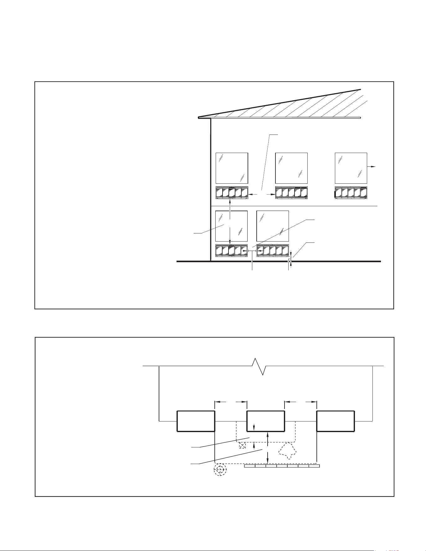
PTACInstallationRecommendations
For proper PTAC unit performance and maximum operating life refer to the minimum installation clearances
below:
Figure 1
PTAC units should be installed no
closer than 12" apart when two
units are side by side. If three or
more PTAC units are to operate
next to one another allow a
minimum of 36" between units.
Also,a vertical clearance of 60"
should be maintained between
units installed. In the interior of
the room the unit should be
located a minimum of 1/4" from the
floor and a minimum of 36"
from the ceiling.
FRP001
For PTACs on the ground floor or anytime obstructions are present, use the following guidelines:
Figure 2
• For minor obstructions
such as lamp poles or small
shrubbery a clearance of
12" from the outdoor louver
should be maintained.
TYPICAL BUILDING ( PLAN VIEW )
• For major obstructions such
as a solid fence, wall or
other heat rejecting device
like a condensing unit, a
minimum distance of 36"
should be kept.
PTAC
12" MINIMUM, MINOR
OBSTRUCTIONS
36" MIMUMUM, MAJOR
36"
POLE
PTAC
12"
36"
36"
SHRUB
PTAC
OBSTRUCTIONS
CONDENSING UNIT
FENCE OR WALL
FRP002
The above suggestions are for reference only and do not represent all possible installations.Please contact Friedrich for information regarding affects of other
installation arrangements.By following these simple recommendations you can be confident that your Friedrich PTAC will provide years of worry free operation.
THREE OR MORE PTACs
ADJACENT 36" MINIMUM
GROUND FLOOR PTACs
6" MINIMUM FROM GRADE
TWO ADJACENT PTACs
12" MINIMUM
TYPICAL
WINDOW
12"
6"
VIEW: OUTSIDE BUILDING ELEVATION
60" VERTICAL
MINIMUM
BETWEEN
PTACs
36"
60"
12
NOTICE
WARNING
Falling Object Hazard
Not following Installation Instructions for
mounting your air conditioner can result
in property damage, injury, or death.
DO NOT allow any pitch toward the inside.
Flashing on all 4 sides of the opening is recommended.
Potential property damage can occur if instructions are
not followed.
For Deep Wall Installation
(Greater than 13
1/4")
See Page 15
The following instructions apply ONLY to walls less than 13 ¼" in depth.
1 The PXDR10 Drain Kit,(optional for new construction) see page
16
if applicable, must be installed before the wall sleeve is installed
into the wall.
2 The External Drain (for new construction or unit replacement) see
page 17 if applicable, must be installed before the wall sleeve is
i
nstalled into the wall.
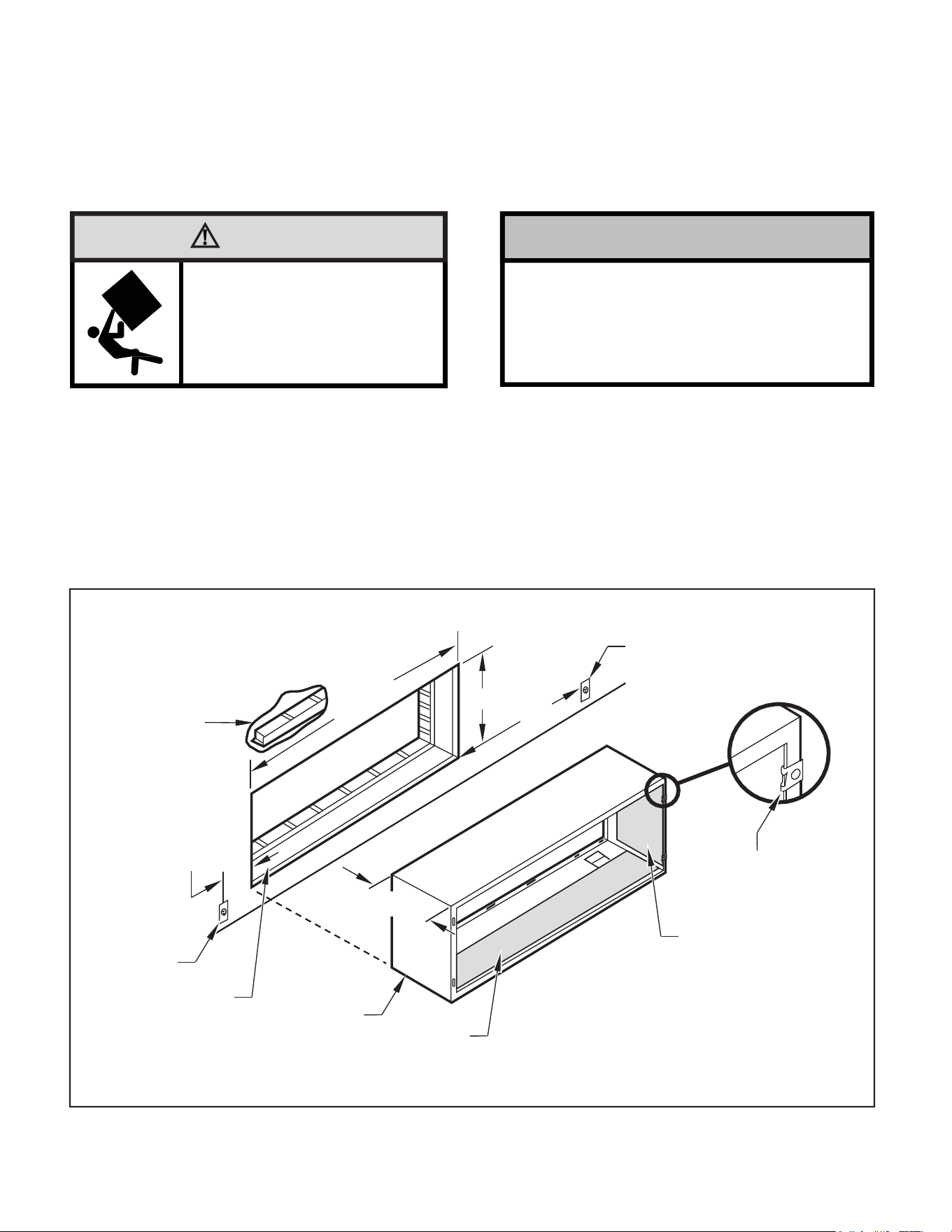
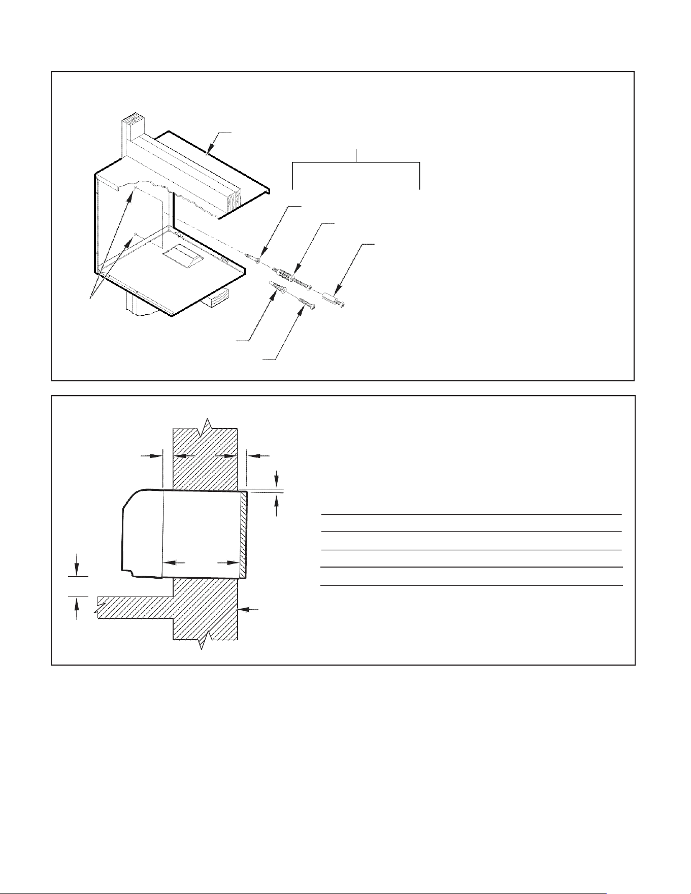
Figure 3
Typical Wall Sleeve Installation
3
From inside the building, position the wa
ll sleeve in the opening and
push it into the wall until it protrudes at least ¼” on the outside
(See Figure 9, Page 14).
4 Position the wall sleeve with a slight tilt towards the outside to
facilitate condensate drainage. It should be level side-to-side and
the front should be ¼ bubble higher than the back.
ELECTRICAL
RECEPTACLE
LINTEL TO SUPPORT
MASONRY WALLS
42-¼"
MIN.
16-¼"
60"
MAX.
20"
MAX.
13-¾"
SMOOTH SIDE OF SCREW
CLIP FACING INTO ROOM
ELECTRICAL
RECEPTACLE
INSULATION
WALL OPENING
WALL SLEEVE
INSULATION
NOTE:
All 230/208V units are manufactured with a 60” power cord and all 265V units with a 18” power cord.
FRP003
Wall Sleeve Installation Instructions (PDXWSEZ/PDXWSA)
NOTE: If the wall covers are not purchased together, the user must purchase a wall cover that meets the G90 standard or salt spray test.
Insure that the unit is only installed in a wall structurally adequate to support the unit including the sleeve, chassis and accessories. If the sleeve
projects more than 8" into the room, a subbase or other means of support MUST be used. Please read these instructions completely before
attempting installation.
13
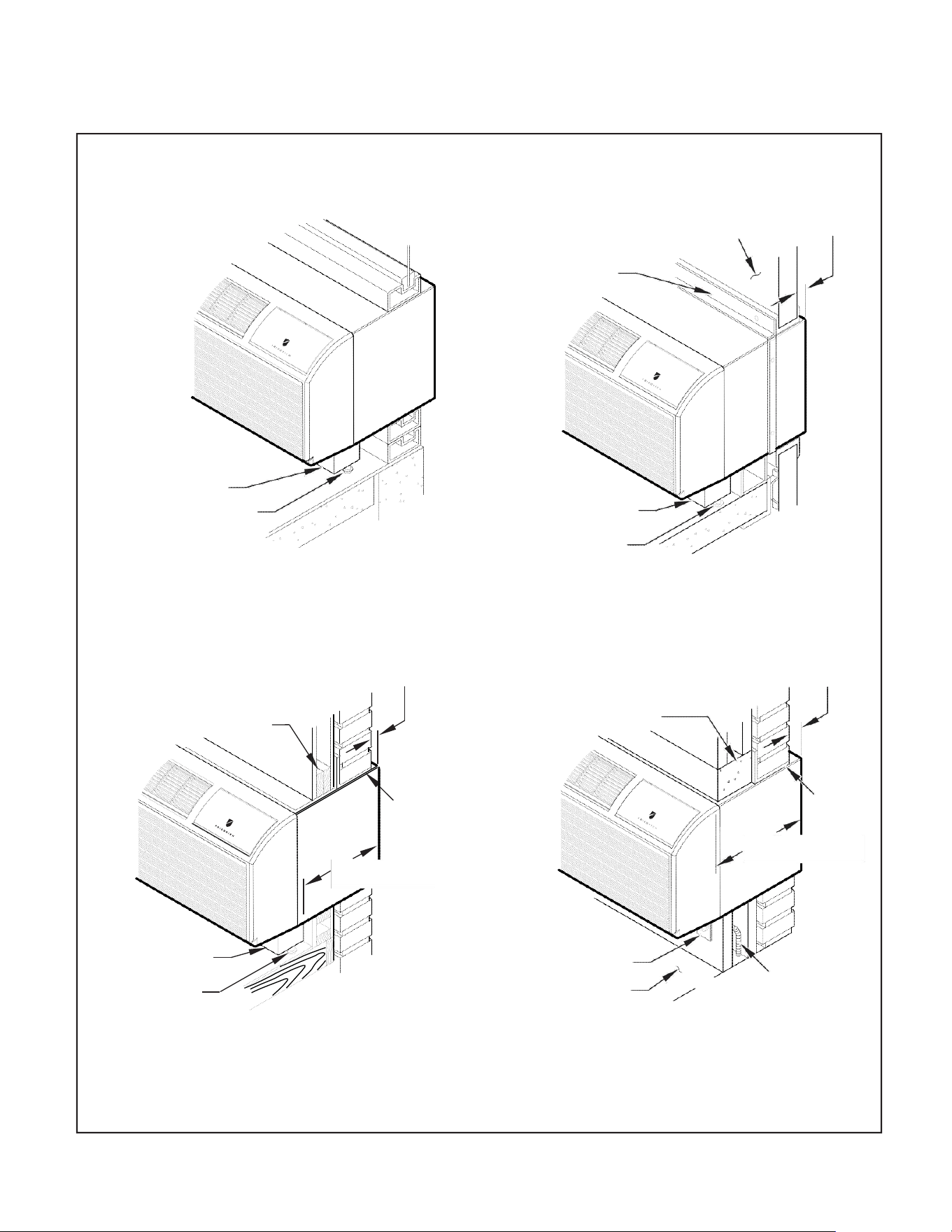
AlternateWall Installations
Figure 4
Panel Wall
Figure 6
CurtainWall
WALL OR
WINDOW
1/4" MIN
PROJECTIO
N
CASE FLANGE
(BY OTHERS)
OPTIONAL SUBBASE
LEVELING SCREW
OPTIONAL SUBBASE
FRP004
LEVELING SCREW
FRP006
Figure 5
Frame and Brick Veneer
Figure 7
Block and Brick Veneer
1/4" MIN
PROJECTION
1/4" MIN
PROJECTION
WOOD FRAME
CONCRETE LINTEL
STEEL
LINTEL
13-3/4" MIN.
STEEL
LINTEL
11" MIN.
WITH SUBBASE
WITHOUT SUBBASE
OPTIONAL SUBBASE
LEVELING SCREW
FRP005
RECEPTACLE
FINISHED FLOOR
POWER SUPPLY CONDUIT
(SUPPLIED BY INSTALLER)
FRP007
NOTE: Follow all wall system manufacturer installation instructions. For sunrooms and modular buildings, adhere to their installation instructions for
supporting and sealing sleeve to their frames. All wall and window/wall installations must provide for proper drainage. In applications where the
drain holes on the PTAC wall sleeve are not exposed beyond the wall an internal drain system is recommended. It is the installer's responsibility
to ensure there is adequate drainage for the PTAC unit.
14
13-¾
"
Figure 8
Wall Sleeve Attachment
WALL
SLEEVE
ALTERNATE
FASTENING METHODS
(Field Supplied)
WOOD SCREW
TOGGLE BOLT
NOTE: The Wall Sleeve must be
horizontally level (side-to-side)
and pitched 1/4 bubble to the
outside when installed in an
opening.
The mounting hole location
EXPANSION
ANCHOR BOLT
should be approximately 2-4”
from the top and bottom of the
sleeve.
MOUNTING
HOLES
PLASTIC ANCHORS
SCREWS
FRP008
Figure 9
Dimensions
A ¼" MIN.
A B C
Dimension*
Allow
for wall
finishing
Allow
for floor
finishing
Allow
for proper
drainage
(Minimum) Min. Max.
(Front-to-Back)
C
No Accessories
¼" ¼"
---
---
With Subbase 1-¾" 3-½" 5"
---
With Lateral Duct ¾"
¼"
---
---
Wall Sleeve Tilt
B
---
---
---
¼"
WALL
* If more than one accessory is to be used, use the maximum
dimension. If the wall thickness is more than 13-¾" - (A+ ¼"),
a sleeve extension must be used.
FRP009
15
5. Drill two 3/16" holes through each side of the sleeve approximately
4" from top and 4" from bottom of sleeve. Screw four #10 x 1"
screws (included) or appropriate fasteners for your installation,
through the holes in the sides of the wall sleeve.
6. Apply sealant around the wall sleeve where it projects through the
inside and outside wall surfaces. Apply the sealant to the screw
heads or the tops of the fasteners used in Step #5.
7. If the chassis and exterior grille are to be installed later, leave the
weatherboard and center support in place, otherwise remove and
dispose of them. (See Figure 13, Page 18).
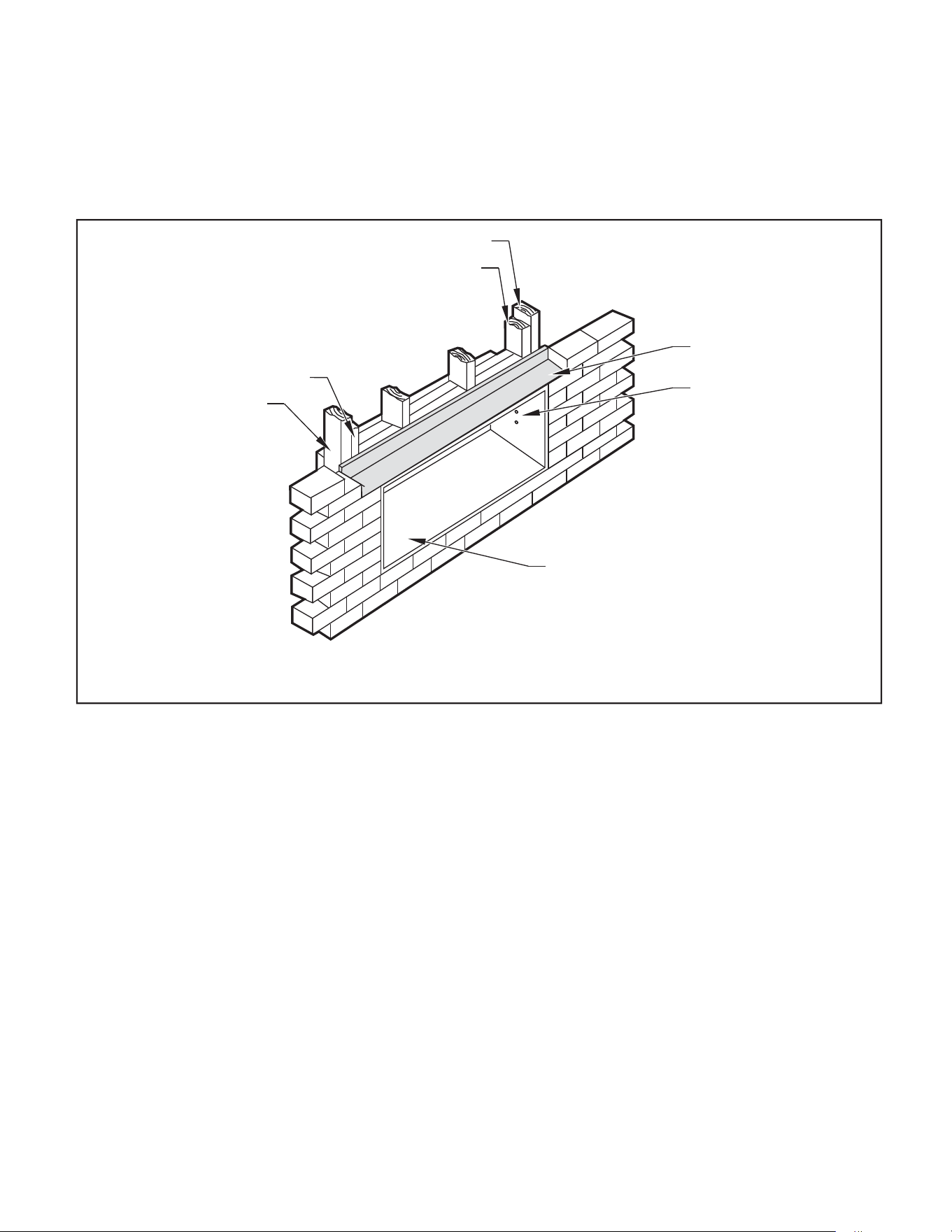
8. Provide a support lintel if the wall sleeve is installed in a concrete
or masonry wall (See Figure 10, Page 15).
Figure 10
Lintel Installation
MAIN STUDS
JACK STUDS
JACK STUDS
MAIN STUDS
LINTEL
MOUNTING
SCREW HOLES
NO HOLES IN BOTTOM OF WALL
SLEEVE UNLESS DRAIN KIT IS USED
NOTE: Construct wall opening to comply with all applicable building codes.
FRP010
One-Piece Deep Wall Sleeve
Installation (PDXWSEXT)
If the wall is thicker than 13 1/4” a deep wall sleeve or wall sleeve extension
MUST be used. The deep wall sleeve may be special ordered through
your Sales Representative.
16
PXDR10DrainKitInstallation
Instructions(optionalfornew
construction)
NOTE: Determine whether drain will be located within the wall, on the
indoor side, or will drain to the exterior of the building. Follow
appropriate instructions below depending on your particular
type of installation.
Internal Drain
NOTE: If installing an internal drain, you MUST install a drain kit on
the wall sleeve before the wall sleeve is installed.
1. Refer to Figure 11 and locate the drain within the “Preferred”
area of best drainage.Maintain at least a ½” clearance from the
embossed area.
2. Using the mounting plate with the ½” hole as a template, mark
and drill two, 3/16” mounting holes and a ½” drain hole in the
sleeve bottom.
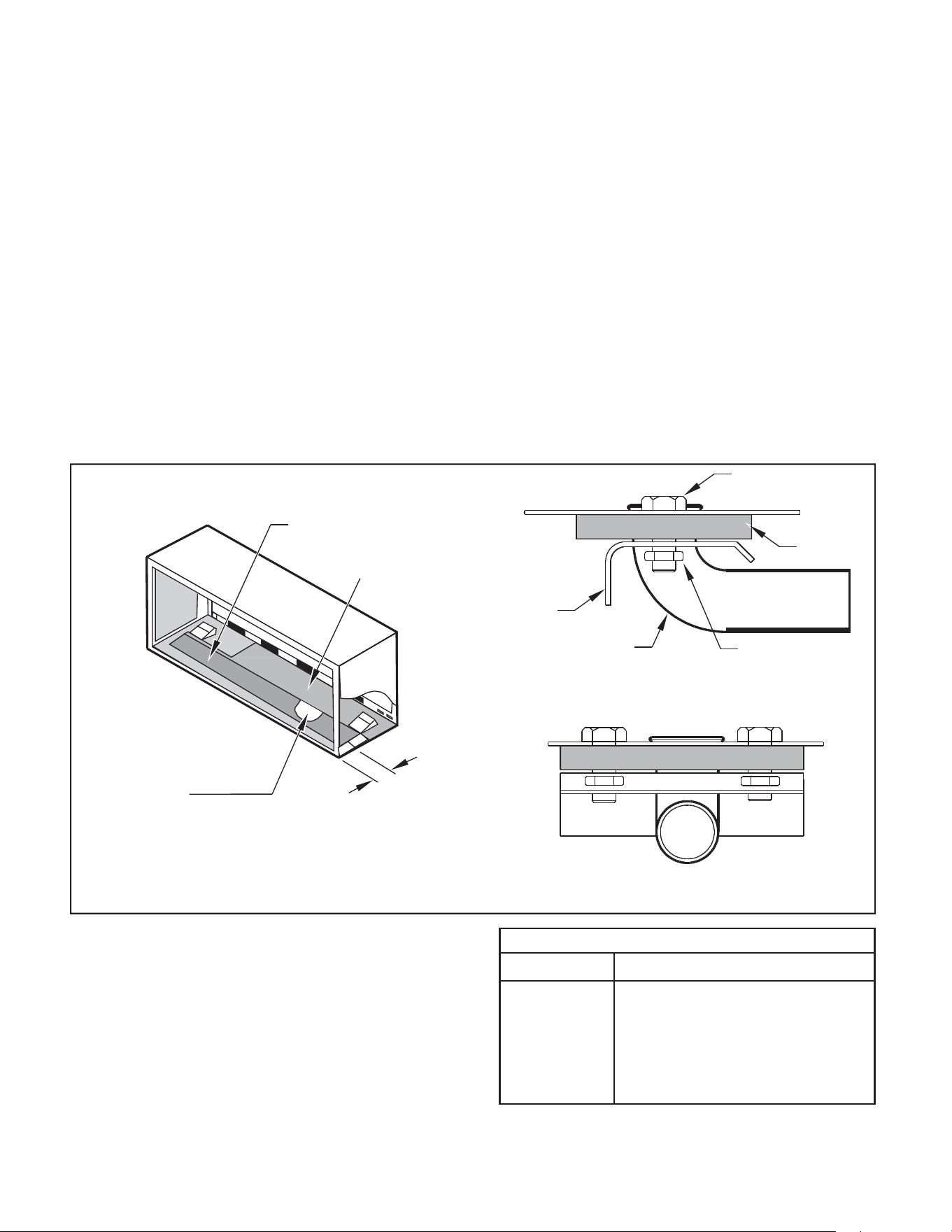
Figure 11
Drain Kit Location and Installation
OPTIONAL AREA
PREFERRED AREA-
NO FOAM INSULATION
3. Remove the backing from the gasket and mount it on the flat
side of the mounting plate (See Figure 12, Page 17). Insert the
drain tube through the hole in the gasket and mounting plate so the
tube flange will be against the wall sleeve.
4. Position the assembly beneath the drilled holes and secure it with
#10-24 x ½" machine screws and lock nuts provided. Seal the tops
of the screws with silicone caulking.
5. Use ½" I D copper tube, PVC pipe, or vinyl hose (obtained locally)
to connect the internal drain tube to the drain system in the building.
6. Referring to Figure 12, Detail A, Page 17, locate and assemble the
two cover plates and gaskets over the drain holes at the rear of
the wall sleeve. Attach them with the #10 sheet metal screws
provided. Make certain that the four overflow slots at the rear of
the wall sleeve are not blocked (See drawing of the back of the
sleeve Figure 12, Page 17).
7. If a deep wall extension (PDXWSEXT) is used, after installing the
field supplied flashing,caulk as required. Be sure to caulk around
the flashing and the wall sleeve where the hole was drilled for the
drain tube.
SCREW
WALL SLEEVE
GASKET
MOUNTING
PLATE
DRAIN TUBE
NUT
SIDE VIEW
IF THE DRAIN MUST BE
LOCATED IN THE OPTIONAL
AREA, THE FOAM INSULATION
MUST BE CUT AWAY AND
REMOVED TO ALLOW ACCESS
3"
TO THE DRAIN.
FRONT VIEW
FRP011
PXDR10
QUANTITY
DESCRIPTION
2
COVER PLATES
1
MOUNTING PLATE
1
DRAIN TUBE
3
MOUNTING PLATE GASKET
4
#10 X ½” SHEET METAL SCREWS
2
#10-24 X ½ ” MACH. SCREWS
2
#10-24 X ½" LOCKNUTS
17
NOTICE
External Drain (for new
construction or unit
replacement)
When using an external drain system, the condensate is removed through
either of two drain holes on the back of the wall sleeve. Select the drain
hole which best meets your drainage situation and install the drain kit.
Seal off the other with a cover plate.
Drain Tube Installation (See Figure 12)
1. Peel the backing tape off the gaskets and apply the sticky side
to one cover plate and one mounting plate as shown in Details
A and B.
2. Place the drain tube through the gasket and the mounting plate
with the flange toward the wall sleeve.
3. Attach the drain tube assembly to one of the two drain holes at the
rear of the wall sleeve. The large flange on the mounting plate is
positioned at the bottom of the sleeve facing toward the sleeve,
Detail B. When the drain tube is positioned at the desired angle,
tighten the screws.
Cover Plate Installation
4. Mount the foam gasket to the cover plate. Using two #10 x ½" sheet
metal screws (provided), attach the cover plate to the remaining
drain hole. Make certain the large flange on the plate is positioned
at the bottom of the sleeve.
5. Discard the additional cover plate, gasket, machine screws, and
locknuts.
If the wall sleeve has not been installed, the drain tube
must be rotated to a horizontal position until after the
sleeve is installed. Tighten the mounting plate screws
when the tube is in the proper position. Make certain that
the four overflow slots at the rear of the wall sleeve are not
blocked (See Figure 12).
When sealing the sleeve on the outside of the building, be
careful NOT to let the sealant block the two condensate
drain holes or the four overflow slots at the bottom flange
of the sleeve.
Potential property damage can occur if instructions are
not followed.
Figure 12
Drain Kit Installation
COVER
PLATE
NUT
MOUNTING
PLATE
FOAM
GASKET
DETAIL A
OVERFLOW
SLOTS
FOAM
GASKET
DETAIL B
SCREWS
½” O.D. TUBE
FRP012
NOTE: The large flange on the mounting plate is positioned at the bottom of the sleeve facing toward the sleeve. The drain tube must be rotated to a
horizontal position to allow for the wall sleeve to be installed into the wall. Once the wall sleeve is installed, return the drain tube to a downward
angle.
18
PXGA Standard Grille
Quantity
Description
1
6
6
Stamped Aluminum Grille
Plastic Grommets
#8 x –" Sheet Metal Screws
PXGAStandardGrille
Installation Instructions
1. Remove the center support and weatherboard if still installed in
the sleeve.
2. Insert six plastic grommets into the grille openings from the outside
of the grille as shown in Figure 13.
3. Insert two #8 x ⅜" sheet metal screws (provided) in the top two
outside edge plastic grommets, and tighten them half way into
the grommets.
4. Grasp the grille by the attached plastic handles. Position
it with the condensate drai n knockouts facing down.
From inside the building, maneuver the grille through the wall
sleeve and pull toward you until the screw heads are inserted
into the keyhole slots at the top of the wall sleeve. Tighten the
two screws completely.
5. Insert the remaining screws into the remaining holes and tighten
securely.
WARNING
Falling Object Hazard
Not following Installation Instructions for
mounting your air conditioner can result
in property damage, injury, or death.
Figure 13
Standard Grille
WEATHERBOARD
CENTER SUPPORT
WALL
SLEEVE
STANDARD
GRILLE
#8 x 3/8”
SHEET METAL
SCREW
WALL SLEEVE
STANDARD GRILLE
PLASTIC GROMMETS
PLASTIC HANDLES
FRP013
19
FUSE/CIRCUIT
BREAKER
Use ONLY type and size fuse or HACR cir-
cuit breaker indicated on unit’s rating plate.
Proper current protection to the unit is the
responsibility of the owner. NOTE: A time
delay fuse is provided with 265V units.
GROUNDING
Unit MUST be grounded from branch circ-
uit through service cord to unit, or through
separate ground wire provided on perman-
ently connected units. Be sure that branch
circuit or general purpose outlet is ground-
ed.The field supplied outlet must match pl-
ug on service cord and be within reach of
service cord. Refer to Table 1 for proper
receptacle and fuse type. Do NOT alter
the service cord or plug. Do NOT use an
extension cord.
RECEPTACLE
A.
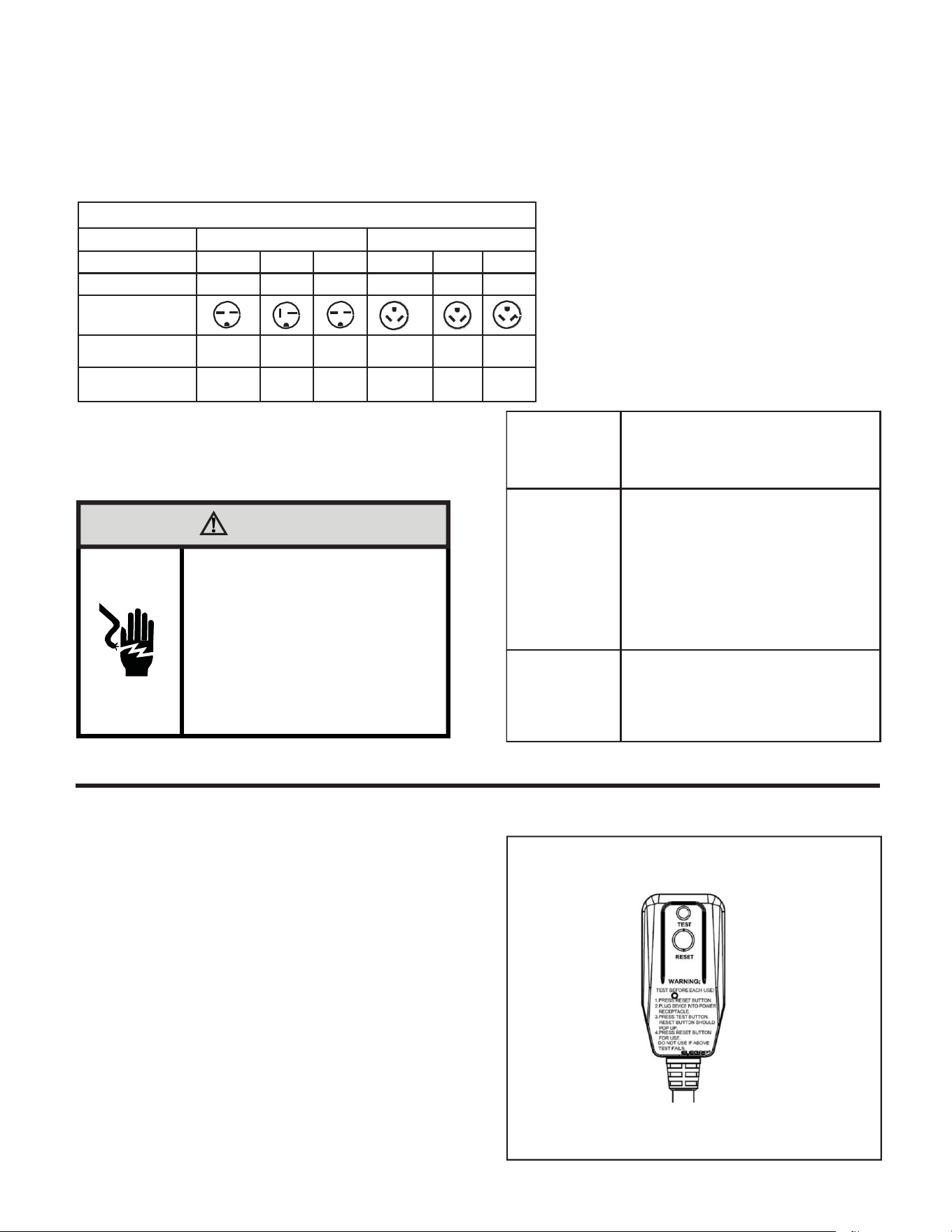
Electrical Rating Tables
All units are equipped with standard power cords.
NOTE: 1.5kW heater only for 12K Btu unit and 2.5kW heater only for 9K Btu unit.
NOTE: Use copper conductors only. Wire sizes are per NEC, always follow local codes as well.
NOTE: Use on a single dedicated branch circuit within specified amperage rating.
Table 1 Receptacles and Fuse Types
Voltage
230V
265V
Amps
15 20 30 15
20
30
Heater Size
1.5/2.5kw
3.5kw
5kw
1.5/2.5kw
3.5kw
5kw
Receptacles
NEMA#
Receptacle
6-15R 6-20R 6-30R 7-15R
7-20R
7-30R
NEMA#
Plug
6-15P 6-20P 6-30P 7-15P
7-20P
7-30P
WARNING
Electrical Shock Hazard
Turn off electrical power before service
or installation.
ALL electrical connections and wiring
MUST be installed by a qualified
electrician and conform to the National
Code and all local codes which have
jurisdiction.
Failure to do so can result in property
damage, personal injury and/or death.
The field supplied outlet must match plug on
service cord and be within reach of service
cord. Refer to Table 1 for proper receptacle
and fuse type. Do NOT alter the service
cord or plug. Do NOT use an extension
cord.
B. Power Cord Information (230/208V models only)
All Friedrich 230/208V PTAC units are shipped from the factory with a
Leakage Current Detection Interrupter (LCDI) equipped power cord.
The LCDI device meets the UL and NEC requirements for cord connected
air conditioners effective August 2004.
To test your power supply cord:
1. Plug power supply cord into a grounded 3 prong outlet.
2. Press RESET.
3. Press TEST ( listen for click;Reset button trips and pops out).
4. Press and release RESET (listen for click;Reset button latches
and remains in).The power supply cord is ready for operation.
Figure 14
Typical LCDI Devices
NOTE: The LCDI device is not intended to be used as a switch. Once
plugged in the unit will operate normally without the need to reset the
LCDI.device.
If the LCDI device fails to trip when tested or if the power supply cord is
damaged it must be replaced with a new supply cord obtained from the
product manufacturer,and must not be repaired.
15/20/30A LCDI Device
FRP014
20
Electrical Wiring for 265 Volt Models
Power Cord Installation
All 265V PTAC/PTHP units come with a factory installed non-LCDI
power cord for use in a subbase.If the unit is to be hard-wired refer to
the instructions below.
NOTE: It is recommended that the PXSB subbase assembly, the
PXCJA conduit kit(or equivalent) be installed on all
hardwire units.If installing a flush-floor mounted unit,make
sure the chassis can be removed from the sleeve for
service and maintenance.
To install the line voltage power leads and conduit to
chassis, follow the instructions below . PXCJA
Conduit Kit is required with this setup.
1. Follow the removal process of the chassis’s junction box .
2. Prepare the 265V(or 230V)power cord for connection to the
chassis’ power cord connector by cutting the cord to the
appropriate length (refer to Figure16 and follow Figure15).Power
cord harness selection shown on Table 2 on page 20.
WARNING
Electrical Shock Hazard
Turn off electrical power before service
or installation.
ALL electrical connections and wiring
MUST be installed by a qualified
electrician and conform to the National
Code and all local codes which have
jurisdiction.
Failure to do so can result in property
damage, personal injury and/or death.
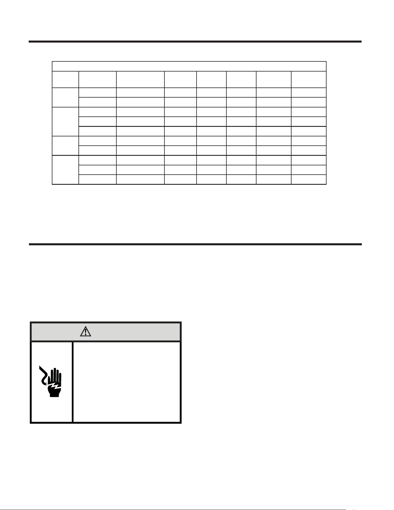
TABLE 2
MODEL HEATER kW Power Cord Kit Voltage
BRANCH
CKT AMPS
MCA
Heater
Watts
Receptacle
PVH09K 2.5(optional) PXPCFA23015 230/208 15
13.9
2550/2090 NEMA 6-15r
3.5(default) PXPCFA23020 230/208 20
19.9
553 0/ 2900 NEMA 6-20r
PVH12K 1.5(optional) PXPCFA23015 230/208 15
13.9
1550/1310 NEMA 6-15r
3.5(default) PXPCFA23020 230/208 20
19.9
553 0/2900 NEMA 6-20r
5.0(optional) PXPCFA23030 230/208 30
27.5
055 0/4135 NEMA 6-30r
PVH09R 2.5(optional) PXPCFA26515 265/277 15
12.0
2700 NEMA 7-15r
3.5(default) PXPCFA26520 265/277 20
16.8
3500 NEMA 7-20r
PVH12R 1.5(optional) PXPCFA26515 265/277 15
7.3
1550
NEMA 7-15r
3.5(default) PXPCFA26520 265/277 20
16.8
3550
NEMA 7-20r
5.0(optional) PXPCFA26530 265/277 30
23.8
5 005 NEMA 7-30r
21
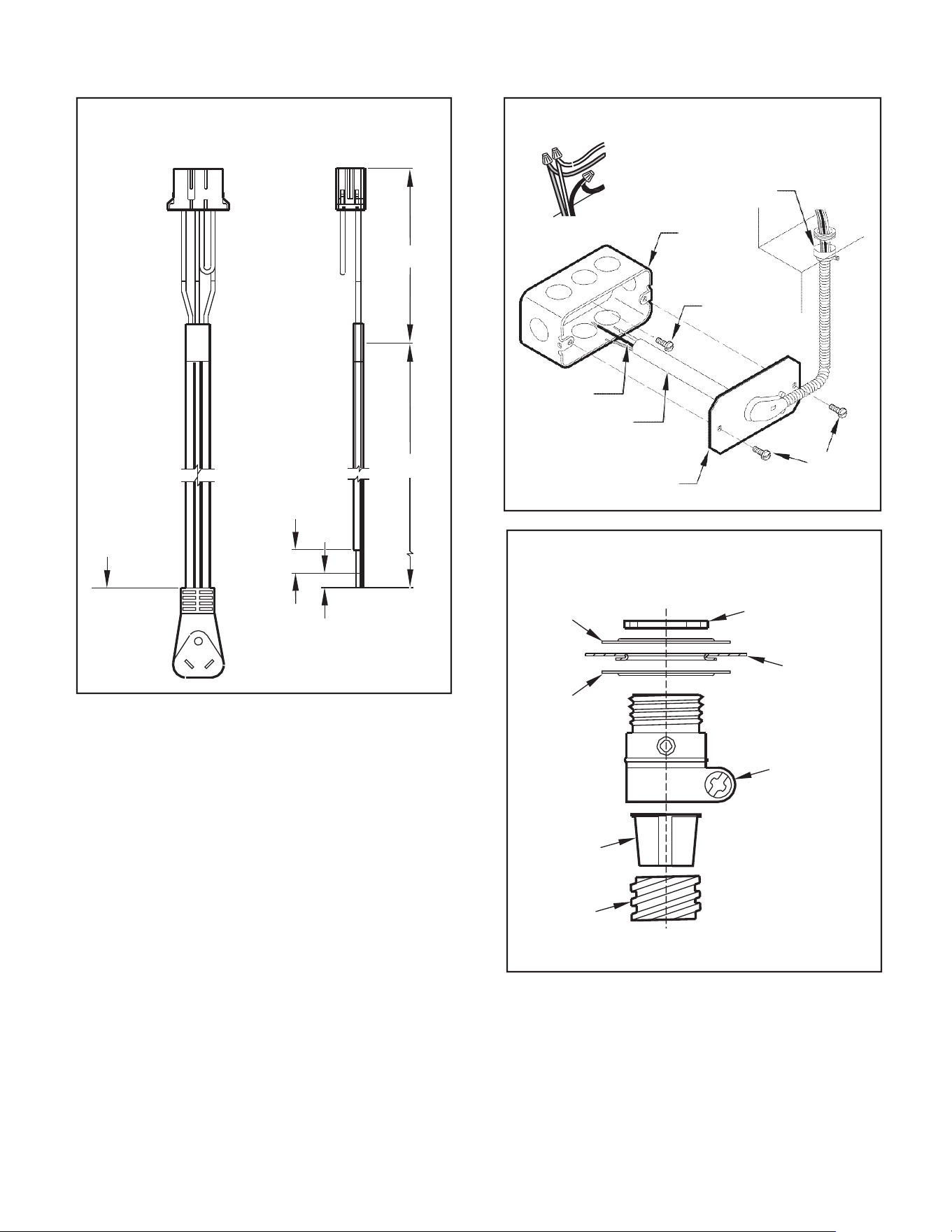
Figure 15
Figure 16
TO CHASSIS JUNCTION
STRAIGHT
CONNECTOR
4.0 IN.
WALL CONNECTION
JUNCTION
BOX
GROUND
SCREW
GROUND
WIRE
HARNESS
EXPOSE
WIRES
(1.0 IN.)
18.0 IN.
JUNCTION
BOX COVER
COVER
SCREW
S
FRP016
TRIM HARNESS
TO LENGTH
Figure 17
STRIP WIRE ENDS (0.5 IN.)
SPACER
LEADING SIDE FOR
WIRE HARNESS INSERTION
LOCKNUT
TO WALL JUNCTION
FRP015
3. Route the cut ends of harness through the conduit connector
assembly and flex conduit sleeve. Be sure to use the s upplied
conduit bushing to prevent damage to the cord by the con duit.
The cord should pass through the Locknut, Spacer, Chassis
Junction Box, Conduit Connector, Bushing, then the Conduit
Sleeve. See Figure 17.
4. Route the cut ends of the power cord through the elbow connector
at the other end of the conduit. Tighten screws on elbow connect
or to secure conduit sleeve.
5. Fasten and secure the elbow connector to the wall junction box
cover with locknut. Place and mount the wall junction box with
the four wall mounting screws making sure to pass the wall lines
through the junction box. Connect and join all wall lines with the
stripped ends using wire nuts. Tighten both screws of the wall
junction box cover to junction box.
SPACER
BUSHING
CONDUIT
SLEEVE
EXITING SIDE FOR
WIRE HARNESS
CHASSIS
JUNCTION
BOX
CONDUIT
CONNECTOR
FRP017
22
Chassis Install Preparation
Check to besurethe wallsleeve, extension (ifused),grille, and drainkitareinstalled properlybeforechassis
installation.
1. Remove the weatherboard and center support from the sleeve (if
still in place). Be sure an outdoor grille is attached.
Figure 18
NOTE: To avoid breaking the door or hinge pins, do not apply excessive
force when installing.
Figure 19
WALL SLEEVE
PIN
CONTRO
L DOOR
INSERT PIN
IN THIS LOCATION
WEATHERBOARD
CENTER SUPPORT
FRP018
FRP019
NOTE: Use a wall sleeve adapter kit (PXSE) if installing a P-Series
chassis in a T-Series sleeve.
WARNING
IMPORTANT: When installing a Friedrich PTAC into an existing sleeve,
it is important to ensure that the unit is installed completely. Inspection
of the air seal between the condenser air baffles and around the indoor
mounting flange is recommended.
In some cases additional gaskets or baffling may be required.
Suffocation Hazards
Keep bag away from babies and children.
Do NOT use in cribs, beds or playpens.
Destroy immediately after opening. This bag
is NOT a toy.
Failure to do so can result in personal injury
and/or death.
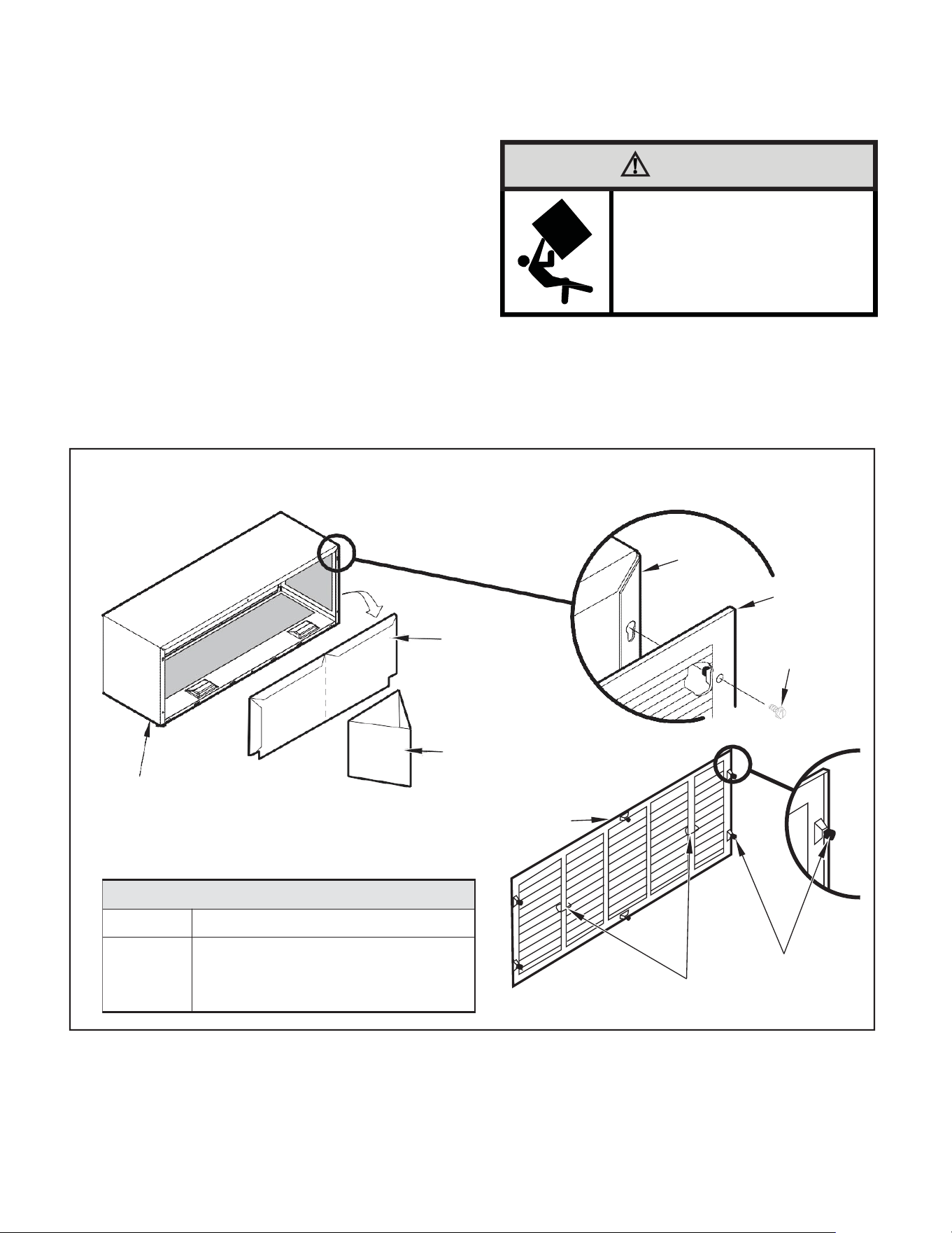
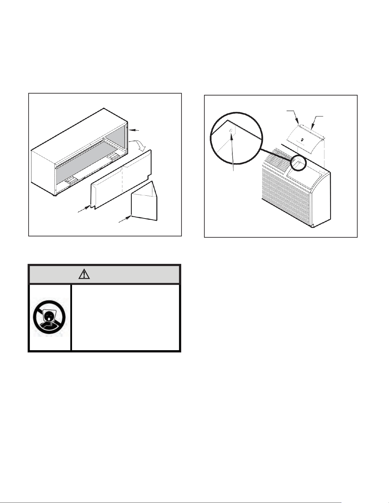
2. Remove the front cover contained in a protective plastic bag
from chassis. Remove the bag and dispose of it properly.
If the control door is not installed, follow these steps:
a. From the front cover, slide the right control door pin into the
hole on the right side of the front cover.
b. Slide the left door pin into the hole on the left side of the
front cover opening.
c. Snap cover into place.
23
CAUTION
Unit Damage Hazard
Failure to follow this caution may result in equipment damage
or improper operation.
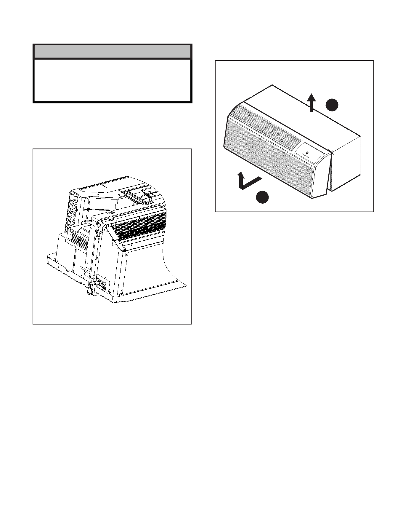
3. Carefully remove shipping tape from the front panel and power
vent door. See Figure 20.
Figure 20
Shipping Tape Location
Figure 21
Removing Front Panel
2
SHIPPING TAPE
FRP020
1
FRP021
4. Remove front panel,see Figure 21.
Pull out at the bottom to release it from the tabs (1). Then lift up (2).
NOTE: If the unit is mounted flush to the floor, the service cord MUST
be rerouted at the bottom of the front cover on the side closest
to the receptacle. A notch MUST be made in the front cover
side where the cord exits the unit. It is the responsibility of
the installer to create an exit notch.
24
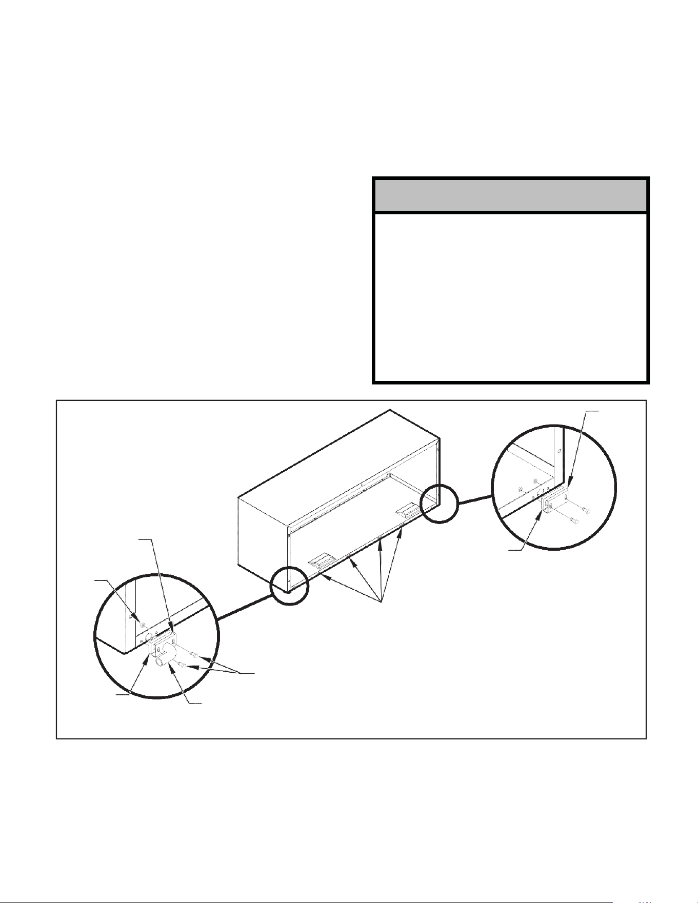
NOTICE
Chassis Installation
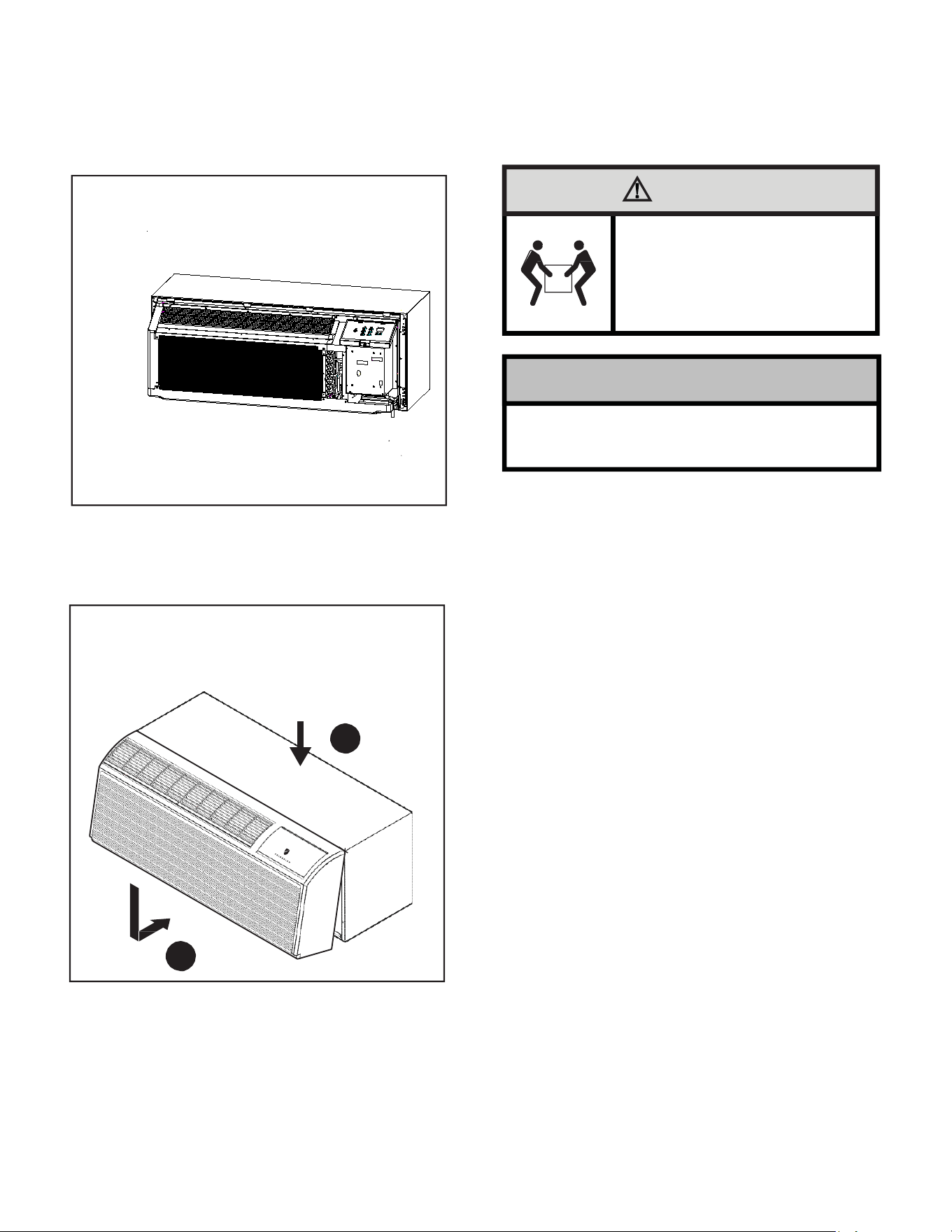
1. Lift unit level and slide unit into wall sleeve until seal rests
firmly against front of wall sleeve.
Figure 22
SecuringUnit
3. Place tabs over top rail.(1)Push inward at bottom until panel
snaps into place(2).
4.
Reinstall front panel.See Figure 23.
CAUTION
Excessive Weight Hazard
Use two or more people when installing
your air conditioner.
Failure to do so can result in back
or other injury.
POWER
SUPPLY
CORD
FRP022
2. Locate the four supplied chassis mounting screws.Insert the
screws through the chassis mounting flange holes that are
aligned with the speed nuts in the wall sleeve.Tighten all four
screws(two per side).
Copper refrigerant tubes are NOT handles.
Do NOT use tubing to lift or move chassis.
To remove the front cover,pull the bottom end forward and lift it up to
clear the L bracket across the top of the chassis.
5. Plug the cord(if applicable)into the appropriate receptacle.
Restore power to the unit.
Figure 23
Replacing Front Panel
1
2
FRP023

25
Friedrich PTAC Digital Control and Unit Features
The new Friedrich digital PTAC has state of the art features to improve guest comfort, indoor air quality and conserve energy. Through the use of specifically
designed control software for the PTAC industry Friedrich has accomplished what other Manufacturer’s have only attempted – a quiet, dependable, affordable
and easy to use PTAC. Below is a list of features and their benifit to the owner.
ONLY TWO MODELS
BETTER
DEHUMIDIIFICATION
SOFT START
OPERATION
M
ERV 8 OUTDOOR AIR
FILTER
REMOTE THERMOSTAT
OPERATION
Some applications require the use of a wall-mounted thermostat. All new Friedrich PTACs may be
switched from unit control to remote thermostat control easily without the need to order a special model
or accessory kit.
INTERNAL DIAGNOSTIC
PROGRAM
The Friedrich digital PTAC features a self-diagnostic program that can alert maintenance to component
failures or operating problems. The internal diagnostic program saves properties valuable time when
diagnosing running problems.
ELECTRONIC
TEMPERATURE
LIMITING
By limiting the operating range, the property can save energy by eliminating “max cool” or “max heat” situ-
ations common with older uncontrolled systems. The new electronic control allows owners to set operat-
ing ranges for both heating and cooling independently of one another.
ROOM FREEZE
PROTECTION
When the PTAC senses that the indoor room temperature has fallen to 50
°
F, the unit will cycle on the
fan (high) and the electric strip heat to raise the room temperature to 55
°
F, and then cycle off again. This
feature works regardless of the mode selected and can be turned off.
CONDENSATE REMOVAL
SYSTEM
Condenser fan utilizes slinger ring technology to pick up condensate from the base pan and disperse it on
to the condenser coil where it evaporates. This helps to cool the coil and increase the energy efciency
of the unit.
DC INVERTER
FreshAire PTACs utilize a DC inverter rotary compressor to ensure part load efficiencies and reliable
operation.
UNIVERSAL ELECTRIC
HEATER
Unit has a universal power cord with 20 Amp coming standard out of the box.
All units are factory run tested to ensure trouble free operation.
FACTORY RUN-TEST

26
DIGITAL DEFROST
THERMOSTAT
The PV-Series uses a digital thermostat to accurately monitor the outdoor coil conditions to allow the heat
pump to run whenever conditions are correct. Running the PTAC in heat pump mode saves energy and
reduces operating costs. The digital thermostat allows maximization of heat pump run time.
INSTANT HEAT
HEAT PUMP MODE
Heat pump models will automatically run the electric heater to quickly bring the room up to temperature
when initially
energized, then return to heat pump mode. This ensures that the room is brought up to
temperature quickly without the usual delay associated with hea
t pump units
.
SEPARATE HEAT/COOL
FAN CYCLE CONTROL
The owner may choose between fan cycling or fan continuous mode based on property preference.
Fan continuous mode is used to keep constant airflow circulation in the room during all times the unit is ‘ON’.
Fan cycle will conserve energy by only operating the fan while the compressor or electric heater is operating.
The ability to set the fan cycling condition independently between heating and cooling mode will
increase user comfort by allowing the choice of only constantly circulating air in the summer or winter
time (unlike other PTAC brands that only allow one selection).
EMERGENCY
HEAT OVERRIDE
In the event of a compressor failure in heat pump mode, the compressor may be locked out to provide
heat through the resistance heater. This feature ensures that even in the unlikely event of a compressor
failure, the room temperature can be maintained until the compressor can be serviced.
CENTRAL DESK
CONTROL
READY(ONLY FOR UNIT
CONTROL)
All Friedrich digital PTACs have low voltage terminals ready
to connect a central desk control energy
management
system.
Controlling
the
unit
from
a
remote location like the front desk can reduce energy
usage and requires no additional accessories on the PTAC unit.
INDOOR COIL
FROST SENSOR
The frost sensor protects the compressor from damage in the event that airflow is reduced or low outdoor
temperatures cause the indoor coil to freeze. When the indoor coil reaches 33°F, the compressor is
disabled and the fan continues to operate based on demand. Once the coil temperature returns to 53°F,
the compressor returns to operation.
ULTRAQUIET
AIR SYSTEM
The PV-Series units feature an indoor fan system design that reduces sound levels without
lowering airflow or preventing proper air circulation.
HIGH EFFICIENCY
The Friedrich PTAC has been engineered so that all functional systems are optimized so that they work
together to deliver the highest possible performance.
DUAL MOTOR
The dual-motor design means that the indoor motor can run at slower speeds which reduces sound
levels indoors.
ROTARY COMPRESSOR
High efficiency rotary compressors are used on all Friedrich PTACs to maximize durability and effi-
ciency.
TOP-MOUNTED
AIR FILTERS
All Friedrich PTAC return air filters and PXFTB replacement filter kits are washable, reusable and
easily accessed from the top of the unit without the removal of the front cover.
FILTERED FRESH
AIR INTAKE
Friedrich PTAC units are capable of introducing up to 40 CFM of outside air into the conditioned space.
The outdoor air passes through a washable mesh screen to prevent debris from entering the airstream.
Outdoor coil endplates made from aluminium reduce corrosion on the outdoor coil common with
other coil designs.
R-32 REFRIGERANT
Friedrich PTAC units use environmentally-friendly refrigerant.
ALUMINIUM ENDPLATES
BREAK-PROOF
CONTROL DOOR
GALVANIZED ZINC
WALL SLEEVE AND
BASE PAN
Galvanized zinc coated steel wall sleeve and steel base pan undergo an 11-step preparation
process, are powder coated with a polyester finish and cured in an oven for exceptional durability.
Break-proof control door design maintains the integrity of the unit.
27
System Configuration
Fresh Air Vent Control
Figure 25
Air Vent Control
To operate the FreshAire module please see Dip switch #3. With dip
switch in the "on" position FreshAire module will be on continuously.
With dip switch in the "OFF" position FreshAire module will be not be
activated.
POWER-DRIVEN VENT DOOR
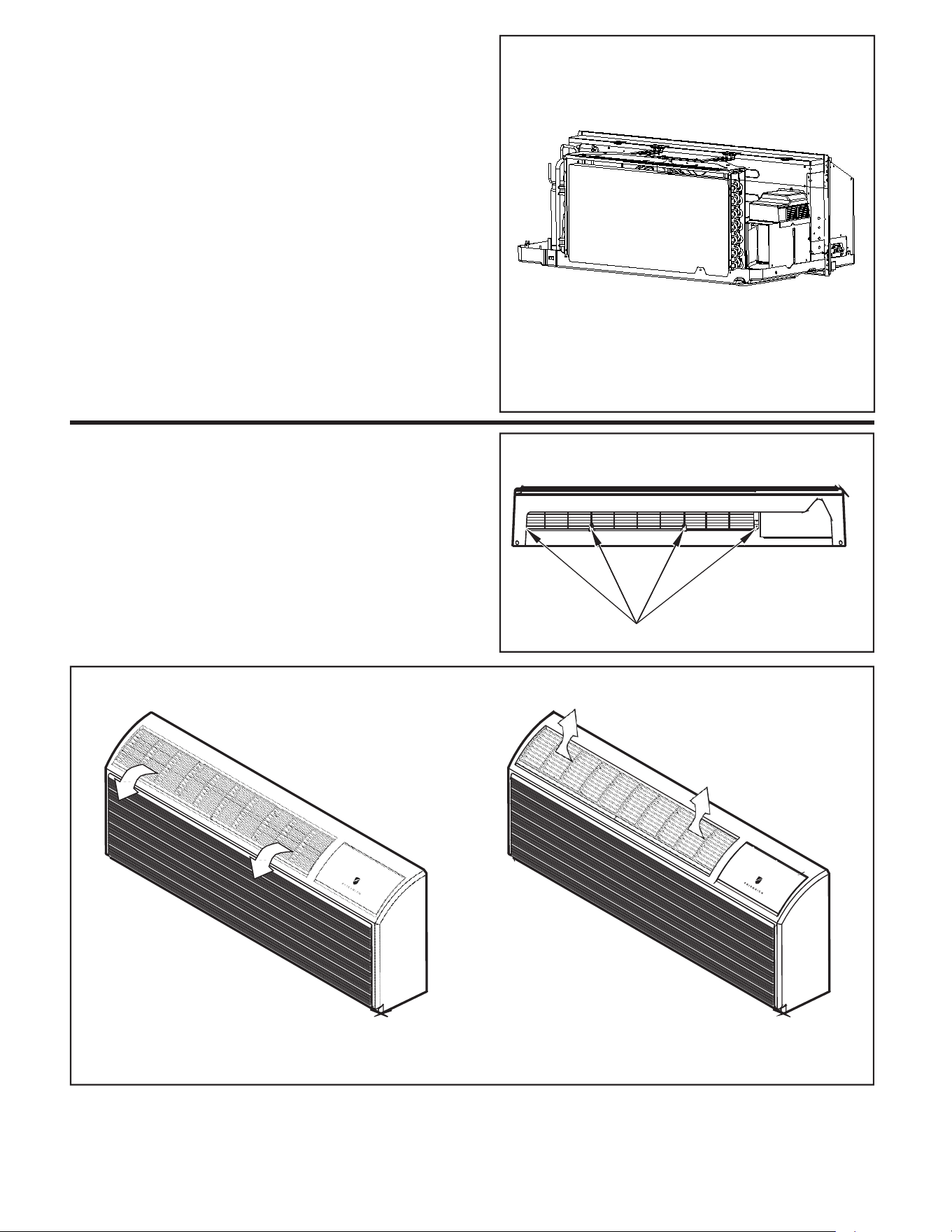
Adjusting Air
Toadjustair direction:
1. Remove front panel. See Figure21.
2. Remove louver screws that hold louver insert in place
(from back side of front panel). See Figure 29.
3. Turn louver insert and rotate180°. See Figure 30.
4. Replace louver insert.
5. Replace screws and front panel.
Figure 26
Backside of Front Panel
LOUVER SCREWS
FRP025
FRP026
Figure 27
Adjusting Louvers
AIR DISCHARGE OUTWARD (Default)
AIR DISCHARGE UPWARD
FRP027
28
8
Digital Control User Input Configuration
The adjustable control dip switches are located at the front portion of the digital Smart Center. The inputs are only visible and accessible with the front cover
removed from the PTAC.
Figure 28
Dip Switches
DIP SWITCH
1 2 3 4 5 6 7
ON
OFF
Reserved
Reserved
Electric memory enable/disable
Room freeze protection
Humidity control fresh air
Electric strip enable/disable
Heat pump enable/disable
Reserved
LOCATION OF
DIP SWITCHES
ON UNIT
FRP028
Switch Description Function Factory setting Option
#1 Reserved / OFF /
#2 Heat pump ON-enable heat pump;
OFF-disable heat pump, run electric heat
only.
HP models-ON
Electric heat only-OFF
OFF-Overrides compressor
operation(HP models only)
#3 Electric strip
ON-enable electric heat;
OFF-disableelectricheat.
ON
Factory set. Do not change.
#4 Humidity control
fresh air
ON-enable;
ON OFF
OFF-disable.
#5
Room
Freeze
Protection
ON-Allows the unit to ensure the indoor room
temperature does not fall below 50℉even
when turned off;
OFF-disable freeze protection.
ON OFF
#6 Electric memory
enable/disable
ON-enable; ON OFF
OFF-disable.
#7 Reserved / OFF /
#8 Reserved / OFF /
Dip Switch Setting
Switch 1-Reserved.
Switch 2-Heat pump enable/disable.
Moving Dip Switch #2 to “OFF” can be set as Emergency Heat Override. In
the unlikely event of a compressor failure, a heat pump unit may be switched
to operate in only the electric heat mode until repairs can be made.
Switch 3-Electric strip enable/disable.
Switch 4-Humidity control fresh air enable/disable
The factory setting is enabled, moving Dip switch 4 to ON and when the user
uses VRPXEMRT2 or VRPXEMWRT2 controller, the unit can control the
fresh air on and off according to the indoor humidity; when the Dip switch is
set to OFF, the indoor humidity can’t control the fresh air on/off.
Switch 5-Room Freeze Protection Units are shipped from the factory With
the room freeze protection enable.Room Freeze Protection can be switched
off at the owner’s preference by moving Dip Switch 5 to “OFF”. This feature
will monitor the indoor room conditions and in the event that the room falls
below 50°F, the unit will automatically run “heating”. This occurs regardless of
mode.
Switch 6-Electric memory enable/disable
The factory setting is enabled. The smart center will remember user’s
setting. After power cut recovery, the unit will operate the same status as
before power cut. Moving Dip Switch 6 to “OFF”will disable this feature, smart
center will no more remember settings.
Switch 7,Switch 8-Reserved.
29
FreshAire
System
Engagement
Method
Mode
Description
SW3-1
ON / OFF
Fresh-Air Fan runs only when Dip Switch is set to ‘ON’
Fresh-Air Fan NEVER RUNS when Dip Switch is set to
‘OFF’
SW3-2
Cycle /
Continuous
Fresh-Air Fan cycles On/Off with the Unit Indoor Fan
when SW3-1 is set to 'ON' & SW3-2 is set to 'OFF'
Fresh-Air Fan runs continuously when SW3-1 is set to
'ON' & SW3-2 is set to 'ON'
2
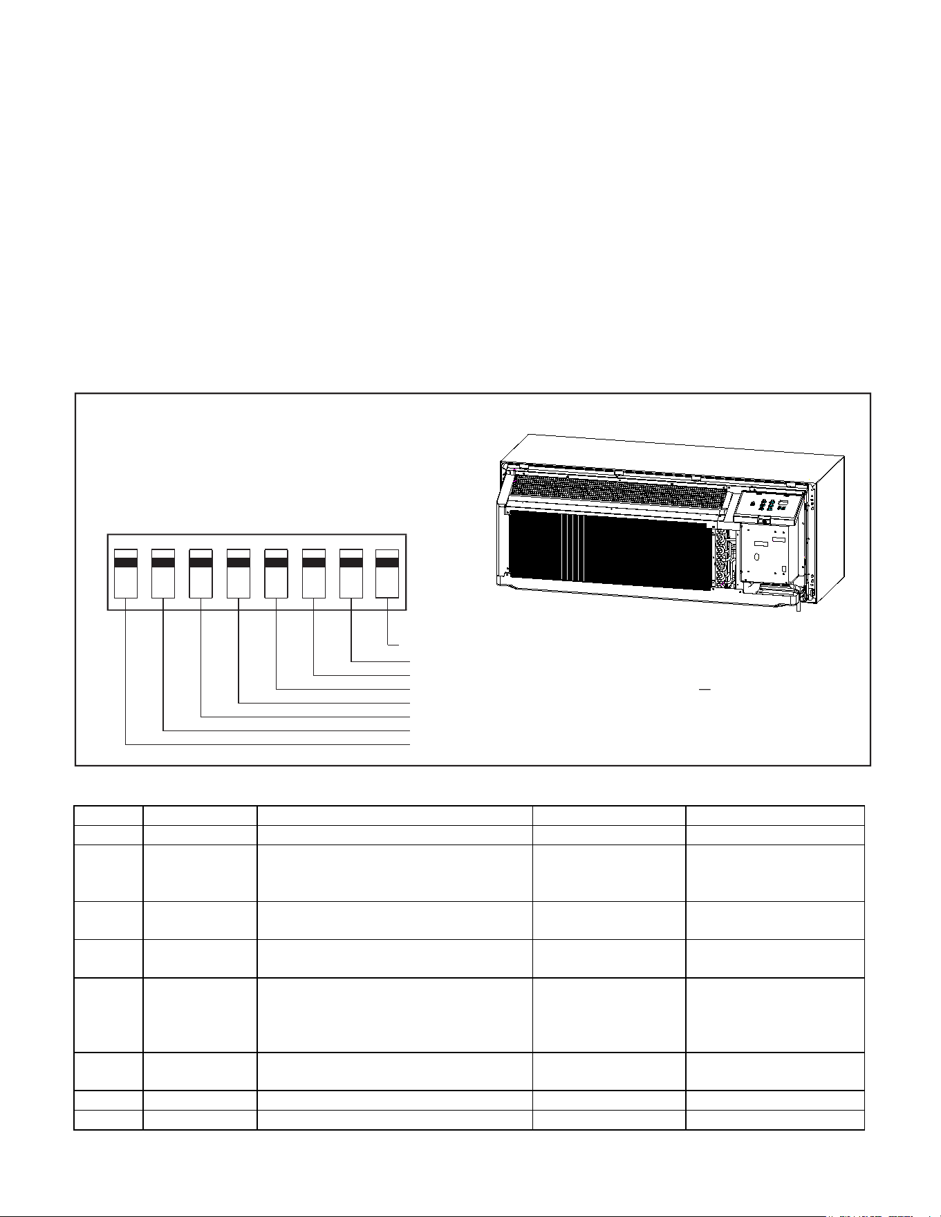
FreshAire System
SW3 DIP SWITCH
ON/CON.
1
OFF/CYC.
SW3-2
SW3-1
T1
T2
T3
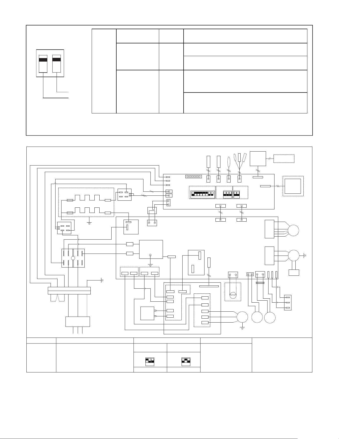
CIRCUIT DIAGRAM
T6
T5
T4
CONTROL
3
IR RECEIVER
PANEL
BK
2 2 2
6
6
BL
H-
HEATER1
REMOTE THERMOSTAT
T6 T5
T4
T1-T3
RD
COM
DISPLAY
HEATER2
WIRE
2
ELECTRIC HEATER2
FUSE
FUSE
ELECTRIC HEA
TER1
FUSE
ON
Note2
2
RELAY2
ON
4
BL
SW1
Note1
ON
Note3
CONTROLLER
0
RD
E.HEA
TER_N
485 PORT
NO
COM
1
E.HEA
TER2_L
SW2
SW3
6
8
2
1
2 3
4
5 6
7
8
1
2 3
1
2
MAINBOARD
RD
TRANS_24V
POWER&RELA
YS
MB_COMM
FUSE
BK
TRANSFORMER
12
3
BL
YE/GN
NO
1
8 6
POWER&RELAYS
MOD_COM
COM
NO
RELAY1
COM
TRANS_IN
INNER
0
4 2
BL
FAN
BK
BK
INPUT_L
EMI FILTER
POWER BOARD
OUTPUT_L
BL
INPUT_N
EARTH
OUTPUT_N
IN 4
OUTER
BK
FAN
YE/GN
RELAY
MB_COMM
RD
TERMINAL BLOCK
DC+ DC-
3
OUT
4-WAY
OR
RD
BK
BL
BL
YE/GN
RD
6
OUTER FAN
BK
WH
BK(BN)
BK
BL
WH
BK
CAPACITOR
ACN
ACL
BL
BL
RD
BL
POWER CONNECTOR
DC-
DC-
BL
RD
HIGH
DC+
JUMPER
DC+
REVERSING VALVE
BK
RD
BK
LOW
L
REACTOR
BK
L
BK
COMP
AIR
MO
DOOR
TOR
FRESH AIR
WH
FAN
FAN SPEED
POWER SUPPLY
BL
BK(BN)
RD
SWITCH
IPM BOARD
COLOR CODE
Note1
SW1 FUNCTION(ON-Enable, OFF-Disable)
Note2
SW2 MODEL TYPE SWITCH
Note3
SW3 FUNCTION GUIDANCE
WARNING:
SWITCHES SW2 ARE FOBBIDEN T
O CHANGE,
OTHERWISE UNIT WILL FAIL TO WORK AND MA
Y
BE DAMAGED !
BK-BLACK WH-WHITE
9K 12K
BN-BROWN OR-ORANGE
ON ON
RD-RED
YE/GN-YELLOW/GREEN
SW2 SW2
BL-BLUE GN-GREEN
1
2 3
1
2 3
1 ON,2 OFF,3 OFF 1 OFF,2 ON,3 OFF
1-Reserved
2-Heat pump
3-Electric heater
4-Humidity control fresh air
5-Freeze protect
6-Auto restart
7-Reserved
8-Reserved
1-Fresh Air Enable/Disable
2-Fresh Air CONTINUOUSL
Y
Running/CYCLES With Indoor Fan
BK(BN)
WH(BL)
GN(YE/GN)
E.HEATER1_L
24V FAN
FRESH_AIR
FA+
FAL
OUTFAN
INFAN
FAH
YE/GN
INNER FAN CAPACITOR
U
V
W
U
V
W
30
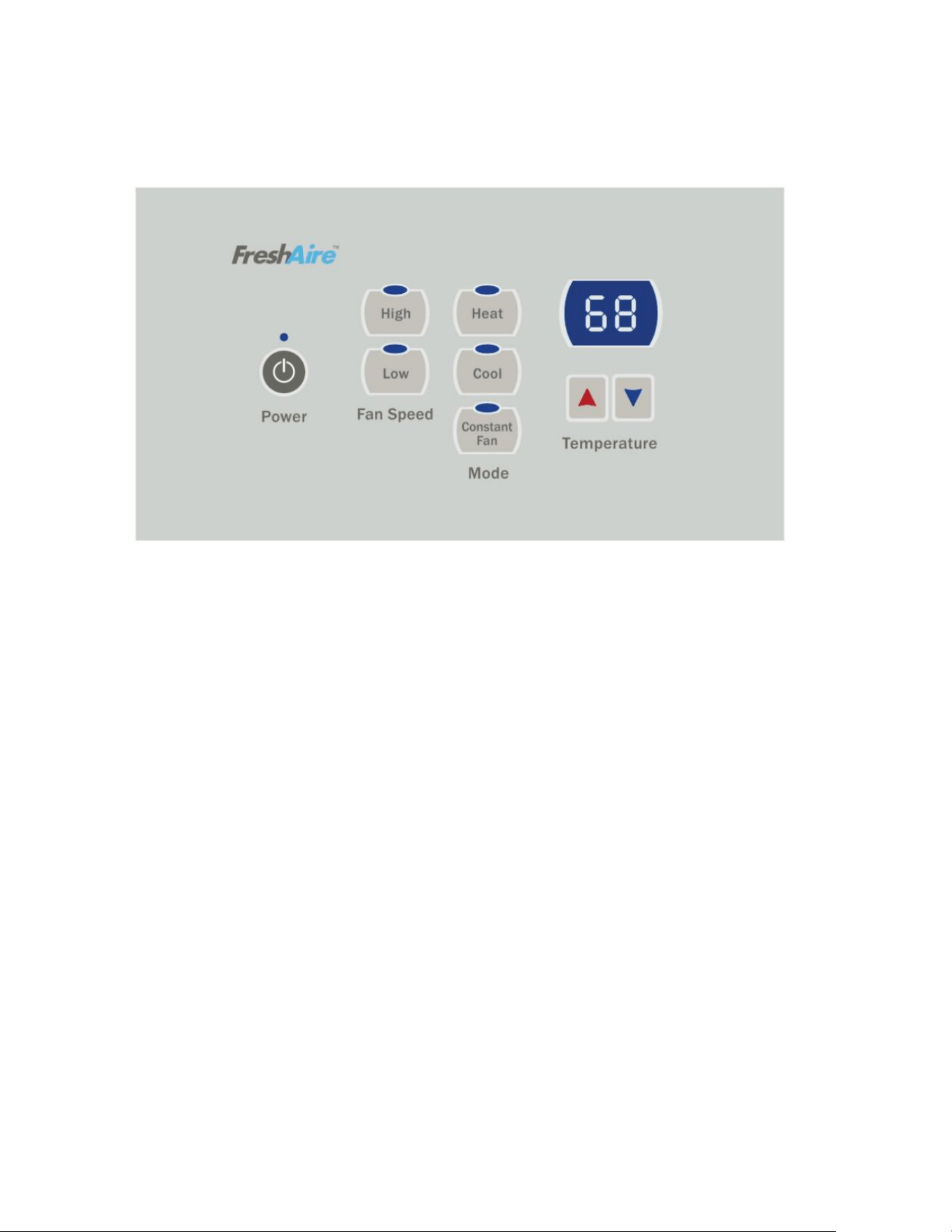
Digital Control Operation
Figure 29
Digital Control Panel
Cooling Mode
Emergency Heat Operation
FRP029
Pressing the “Cool” button after turn the unit on will put the unit into
cooling mode. Press “UP” or “DOWN” button to adjust the set point, the
unit will start the compressor and run appropriate frequency to maintain a
comfortable room temperature. The compressor will come on anytime that
the room temperature is 2℉above the set point. The fan will come on with
compressor.
Heating Mode
After turn on the unit, press the “Heat” button will put the unit into heating
mode.
Heat Pump Models (PVH)
When the “Heat” button is pressed initially the unit may call for electric
strips to bring the room to the set point. When the room temperature falls
2℉below the set point, the unit will turn on the compressor or electric
strip. The fan will run with compressor or electric strips. When the outdoor
ambient temperature falls below 32°F or outdoor coil temperature drops to
5℉, the unit will operate the electric strip instead of heat pump. During
heat pump mode, CPU detects the outdoor coil gets freeze, unit will go to
defrost. During the defrost operation (10min at most), there will be no
heating provide. After finishing defrost, electric heating will come on to
warm the room quickly.
In the event of a compressor failure in heat pump mode, the compressor
may be locked out to provide heat through the electric strip heater
automatically. This feature ensures that even in the unlikely event of a
compressor failure, the room temperature can be maintained until the
compressor can be serviced. If the unit still can’t run electric heater stably,
switch Dip switch 2 to OFF, it controls the emergency heat setting.
Constant Fan
Pressing the “Constant Fan” button will provide constant or cycle fan
operation in cooling or heating modes. The fan speed selection is
made by pressing either “High” or “Low” fan speed button.
31
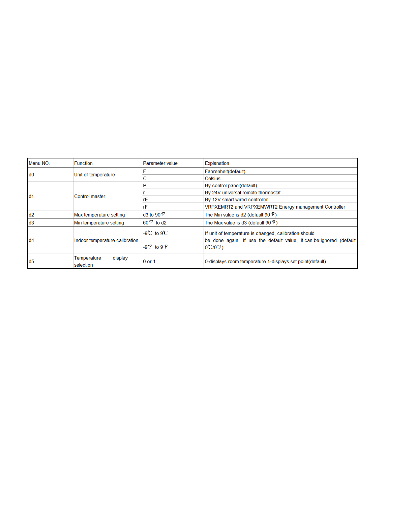
Settings- Detailed Configurations
This section is about how to set the unit operating parameter, include display temperature unit, Fahrenheit or Celsius, control master, temperature
limit, temperature calibration, display set point or room temperature.
Under OFF mode, hold [Cool] and [Low] two keys at the same time continuously for 5 seconds. This time displays ‘d0’, indicates that system
has entered the senior operation status.
[Cool] key is used to switch parameter code and parameter value;
[UP] or [DOWN] keys are used to switch parameter code or set parameter value; [Power] key is used to save
and exit settings.
One example:
Setting target:d0(C),d1(r), d2(88℉),d3(58℉),d4(-1℉),d5(1).
Step1: hold [Cool] and [Low] two keys at the same time continuously for 5 seconds. Display:'d0'
Step2: short press [Cool] key. Display: 'F'(setting d0 has finished)
Step3: short press [Cool] key. Display:'d0'
Step4: short press [UP] key. Display:'d1'
Step5: short press [Cool] key. Display: 'P'
Step6: short press [UP] or [DOWN] key. Display: 'r' (setting d1 has finished)
Step7: short press [Cool] key. Display:'d1'
Step8: short press [UP] key. Display:'d2'
Step9: short press [Cool] key. Display:'90'
Step10: short press [DOWN] key twice. Display:'88' (setting d2 has finished)
Step11: short press [Cool] key. Display:'d2'
Step12: short press [UP] key. Display:'d3'
Step13: short press [Cool] key. Display:'60'
Step14: short press [UP] key twice. Display:'58' (setting d3 has finished)
Step15: short press [Cool] key. Display:'d3'
Step16: short press [UP] key. Display:'d4'
Step17: short press [Cool] key. Display:'0' (setting d4 has finished)
Step18: short press [Power] key to exit.

32
Remote Control Thermostat
Installation
Install Thermostat
1. Approximately 5 ft from the floor.
2. Close to or in a frequently used room,preferably on an inside wall.
3. On a section of wall without pipes or ductwork.
The Thermostat should NOT be mounted:
1. Close to a window, on an outside wall, or next to a door leading
outside.
2. Where it can be exposed to direct sunlight or heat, such as the sun,
a lamp,fireplace or any other temperature radiating object which
may cause a false reading.
3. Close to or in the direct airflow of supply registers and/or return
air grilles.
4. Any areas with poor air circulation, such as a corner,behind a
door,or an alcove.
Remote Thermostat and
Low Voltage Control
Connections
RemoteThermostat
All Friedrich PV model PTAC units are factory configured to be controlled
by either the chassis mounted Smart Center or a 24V remote wall mounted
thermostat.The thermostat may be auto or manual changeover as long as
the control configuration matches that of the PTAC unit.
NOTE: All PV models require a single stage cool, dual stage heat
thermostat with an B reversing valve control.The Friedrich RT7 thermostat
can be configured for either model.
To control the unit with a wall mounted thermostat
follow the steps below:
1. Unplug the unit before doing any work
2. Remove the low voltage terminal block from the unit.
3. Remove the fireproof cover from the unit.
4. Connect the corresponding terminals from the wall thermostat to the
terminal block.
5. Reinstall the fireproof cover.
6. Plug the terminal block on the unit.
7. Restore power to the unit.
8. Under OFF mode, set menu NO.'d1' to “r”, details refer to the
previous section "Settings- Detailed Configurations" on page 31.
9. The unit is now controlled by the wall thermostat only.
10. If the accessory escutcheon kit (PDXRTA) is to be used, install
it over the existing control panel.
NOTE:The unit control panel no longer controls the unit. To restore the control
panel, set menu NO.'d1' back to "P", details refer to the previous section "Settings-
Detailed Configurations" on page 2.
ThermostatConnections
R = 24V Power from Unit
Y = Call for Cooling
W = Call for Heating
B = Reversing Valve Energized in Heating
Mode
GL = Call for Low Fan
GH = Call for High Fan
C = Common Ground
*If only one G terminal is present on thermostat connect to GL for low
speed fan or to GH for high speed fan operation.
Figure 30
Control board with optional PDXRTB escutcheon kit
installed
FRP030
33
Front Desk Control Terminal
(ONLY FOR UNIT CONTROL)
The Friedrich PV model PTAC has built-in provisions for connection to an
external switch to control power to the unit. The switch can be a central
desk control system.
For front desk control operation, connect one side of the normal open
switch to the R terminal and the other to the FD terminal.
The control logic as below:
(a). Turn ON unit: short R and FD then release for one time within 5s.
(b). Turn OFF unit: short R and FD then release for twice within 5s.
(c). Force unit shut down for one time: short R and FD short over 5s.
NOTE: After forced shut down, you can turn on the unit again by control
panel.
NOTE: The desk control system and switches must be field supplied.
Energy Management
Sometimes known as Front Desk Control, an input is provided so that the
unit can be manually disabled from a remote location. If the unit detects
24Vac on this input, it will automatically turn itself off.If no voltage is
detected on the input , the unit will run normally.
NOTE: It is the installer's responsibility to ensure that all control wiring
connections are made in accordance with the installation
instructions.Improper connection of the thermostat control
wiring and/or tampering with the unit's internal wiring can
void the equipment warranty.Other manufacturer's PTACs
and even older Friedrich models may have different control
wire connections.Questions concerning proper connections
to the unit should be directed to Friedrich.
WARNING
Electrical Shock Hazard
Turn off electrical power before service
or installation.
ALL electrical connections and wiring
MUST be installed by a qualified
electrician and conform to the National
Code and all local codes which have
jurisdiction.
Improper connection of the thermostat
control wiring and/or tampering with the
units internal wiring may result in property
damage, personal injury or death.
34
Final Inspection & Start-up Checklist
Inspect and ensure that all components and accessories have been
installed properly and that they have not been damaged during the
installation process.
Check the condensate water drain(s) to ensure they are adequate for
the removal of condensate water, and that they meet the approval of
the end user.
Ensure that all installations concerning clearances around the unit
have been adhered to.Check to ensure that the unit air filter, indoor
coil, and outdoor coil are free from any obstructions.
Ensure that the entire installation is in compliance with all applicable
national and local codes and ordinances that have jurisdiction.
Secure components and accessories, such as the chassis, decorative
front cover and control door.
Start the unit and check for proper operation of all components in
each mode of operation.Instruct the owner or operator of this units
operation, and the manufacturer’s recommended routine maintenance
schedule.
NOTE: A log for recording the dates of maintenance and/or service
is recommended.
Present the owner or operator of the equipment with the Installation
& Operation manual, all accessory installation instructions, and the
name, address and telephone number of the Authorized Friedrich
Warranty Service Company in the area for future reference if
necessary.
WARNING
Electrical Shock Hazard
Unplug Unit or turn off electrical power
to unit prior to performing maintenance
procedures
Failure to do so can result in electrical
shock or death
Decorative Front
Use a damp (not wet) cloth when cleaning the control area to
prevent water from entering the unit, and possibly damaging the
electronic control.
The decorative front and the cabinet can be cleaned with warm
water and a mild liquid detergent. Do NOT use solvents or
hydrocarbon based cleaners such as acetone, naphtha, gasoline,
benzene, etc.
The indoor coil can be vacuumed with a dusting attachment if it
appears to be dirty. DO NOT BEND FINS. The outdoor coil can
be gently sprayed with a garden hose.
Front Panel Air Filter
To ensure proper unit operation, the air filters should be cleaned at least
monthly, and more frequently if conditions warrant. The unit must
be turned off before the filters are cleaned.
To remove the air filters,filter grasp the top of the filters and lift out of the
front cabinet. Reverse the procedure to reinstall the filters.
Clean the filters with a mild detergent in warm water, and allow them to
dry thoroughly before reinstalling.
Routine Maintenance
To
ensure proper
unit
operation
and
life expectancy the following mainte-
nance procedures should be performed on a regular basis.
The interior of unit should be maintained by HVAC techs only.
WARNING: Service of this product (aside from filter
maintenance) shall only be performed by trained service personnel. Refer to
the Service Manual for procedures on how to insp
ect and maintain the interior
of the unit and its components. Scan the QR code which will help you locate
the service manual online.
Coils & Chassis
The indoor coil and outdoor coils and base pan
should be inspected periodically (annually or semi-
annually) and cleaned of all debris (lint, dirt, leaves,
paper, etc.) as necessary. Under extreme conditions,
more frequent cleaning may be required.
Wall Sleeve
Inspect the inside of the wall sleeve and drain
system periodically (annually or semi-annually) and clean as
required. Under extreme conditions, more frequent
cleaning may be necessary.
Blower Wheel / Housing / Condenser Fan / Shroud
Inspect the indoor blower and its housing, evaporator
blade, condenser fan blade and condenser shroud
periodically (yearly or bi-yearly) and clean of all debris (lint,
dirt, mold, fungus, etc.).
Fresh AIr Intake Screen
The Fresh Air Intake Screen should be inspected every 60 days
and cleaned of all debris (lint, dirt, leaves, paper,
etc.) as necessary. Under extreme conditions, more frequent
cleaning may be required.
35
Basic Troubleshooting
Malfunction
Possible Reasons
S olution
Start Failure
power line bad, units don’t have power
supply.
Check the indicator LED on the LCID power head,
it should be lit up, if not, push the RESET button,
if still don’t have voltage, but power grid has
output, you need to change the power cord.
Power cord protection trip.
Check the power cord if somewhere is broken,
push the RESET button. If not solved, replace the
power cord.
Power cord isn’t fixed well.
Check that whether power cord is fixed well.
PCB fuse is broken.
Check if any load (in fan, out fan, reversing valve,
power transformer) is short circuit. Eliminate the
error and replace the fuse with the same type.
Bad contact between main board and
control panel.
Check the contact wires, make sure all contact
well.
Compressor delay start.
It’s normal, compressor will start after 3 minutes
Power fail protection.
When power on, because of auto-restart, unit
will delay starting in 120~240s
Unit in protection mode.
Please check the ERROR CODE
Main board or Control panel is bad.
Replace the main board or control panel
Control panel do not work
When the unit is switch to 24V remote
thermostat or 12V smart controller, the
control panel will not be functioning.
If you need to use control panel to take control,
you need to switch the control master. See the
SENIOR SETTINGS section.
Indoor fan/outdoor fan not function or run
slowly
Fan is locked by something or the power
wires are not fixed well; fan capacitor is not
fixed well; fan capacitor is out of service life.
Disconnect the power cord, check whether the
fan can run smooth by hand or other tools,
whether motor wire is fixed well. For the slow
running speed, you could change a new
capacitor.
Not cooling/heating adequately
Something may block the indoor/outdoor air
outlet.
Make sure that there is no obstacle at the
indoor/outdoor air outlet.
Make sure that the grill is suitable for the unit,
inappropriate grill will cause the compressor
being protected; make sure that the grill has
more than 70% turn over.
Set unsuitable temperature.
Set higher/lower temperature by the control board.
NOTE: temperature setting restriction will restrict
the setting temperature. See the SENIOR
SETTINGS section.
Indoor air filter is dirty.
Should clean the filter every month at least.
Room is hot/cold.
Let unit run a little longer that room temperature
will be lower/higher.
Heat leakage between indoor and outdoor.
Block the leakage place.
Indoor coil not cold/heat.
Charge the refrigerant.
Unit has noise
Some moving parts of the unit get loose
fixing or cause bad vibration.
Something in the air way.
Make sure that all moving parts are assembled
well, and nothing is in the air way.
Bad smell when heating
The dust on the E-heater is heating.
The bad smell will disappear a little later.
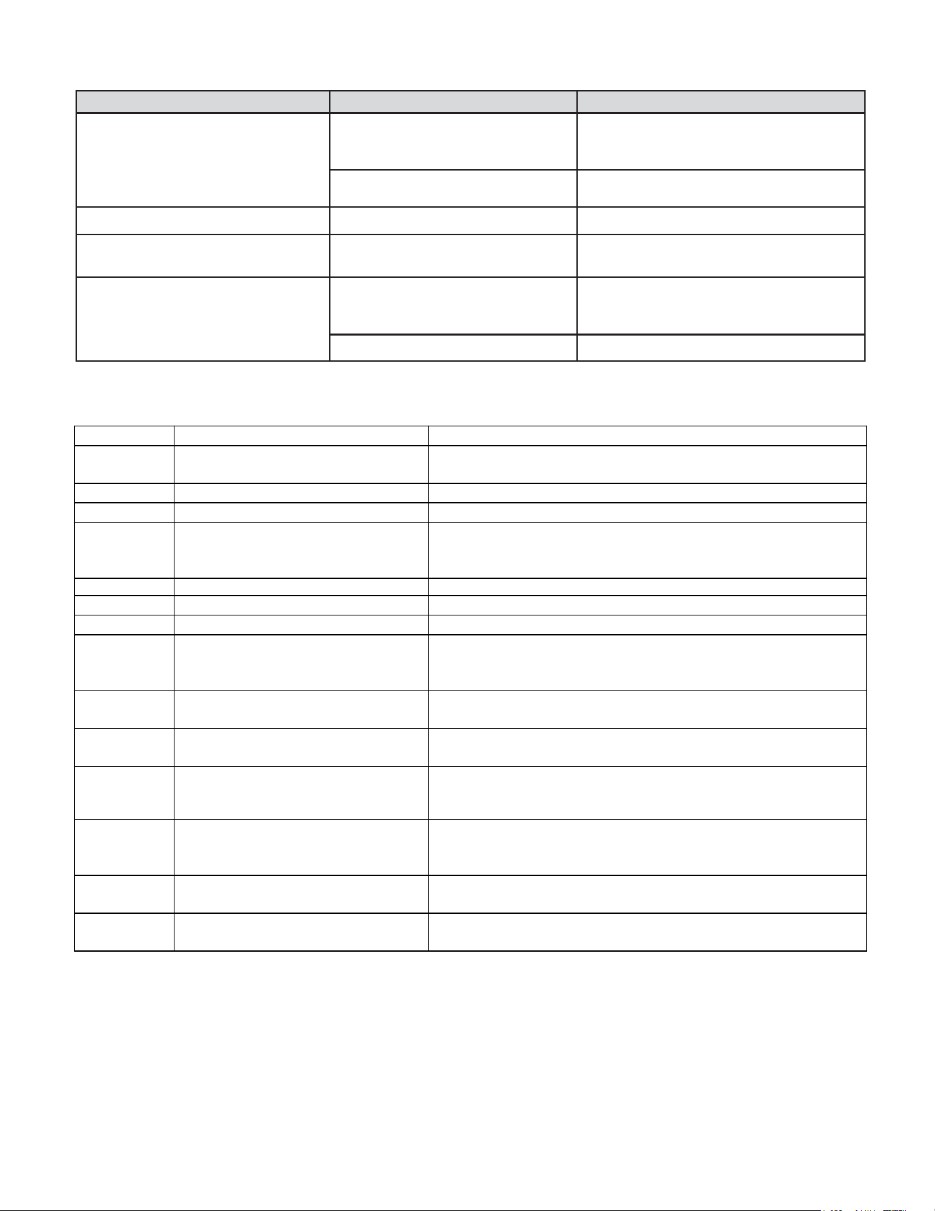
36
Malfunction
Possible Reasons
Solution
Outlet temperature is not always
cooling/heating
Outlet temperature is not high enough when
heating by heat pump.
When outdoor ambient temp is low, the heat
pump will not be able to offer enough heat. Soon
after that, the E-heater will come on to heat.
Fan stops when cooling/heating.
It is normal when the CONSTANT FAN is OFF.
Youcan enable the CONSTANT FAN.
Outdoor is dripping water
Not install the drain pipe kit.
Install the drain pipe kit.
Indoor is dripping water
Wall sleeve is not installed correctly.
Install the wall sleeve according to the
installation manual.
Indoor coil freeze
Outdoor temperature is too low in cooling
mode.
When outdoor temperature is drop to 55°F(12.8℃)
or below, it will cause that indoor coil freeze. Open
the fresh air door, and running at fan mode.
Filter is dirty.
Clean the filter to recover the normal air flow
Error code and solutions
ERRORCODE Meaning Solutions
E1 Communication failure between indoor
unit and outdoor unit
Check the communication cables; make sure they are firmly connected. If
the cables are broken, replace them.
E2 Indoor Temp Sensor Open/short
Check the plug is firmly connected. If the sensor is broken, replace it.
E3 Indoor Coil Sensor Open/short Check the plug is firmly connected. If the sensor is broken, replace it.
E4
E5 IPM Over Heat
Remove obstacles in the air path that resists heat interchange.
E6 Outdoor Temp Sensor Open/Short Check the plug is firmly connected. If the sensor is broken, replace it.
E7 Outdoor Coil Sensor Open/Short Check the plug is firmly connected. If the sensor is broken, replace it.
EC Compressor Fail Starting/DC-Inverter Fail
1. Check the DIP switch SW2 on the main board (3-position, in red color)
is correctly matched with the unit capacity, refer to the wiring diagram.
Make sure the compressor power cord is firmly and correctly connected.
EF Power Cord Error For 9KBTU, 30A Is
NOT Allowed
Change the power cord to 15A or 20A.
P1
Cooling/Heat Pump Over Load,
Ou
tdoor/Indoor Coil Over Heat
Make sure indoor and outdoor unit vents are not blocked. Clear the air
filter and the condenser after a long time use.
P2 IPM Over Current Protection
P4 Compressor Discharge Over Heat
Protection
P7
DC Over/Under Voltage Protection Make sure the power supply is within the requirement (AC208/230V -
10%+10%)
F8
Internal fan secular malfunction
Check the internal fan plug is firmly connected. If the internal fan motor
is broken, replace it.
1.
Indoor Air Outlet Sensor Open/Short
2.
Outlet Air Over Heat In Electric
Heating Mode
1.
Check the plug is firmly connected. If the sensor is broken, replace it.
2.
In E-Heating mode, check if any obstacles around the air path, remove
them. Make sure the air flow is not blocked.
1. Check the DIP switch SW2 on the main board (3-position, in red color)
is correctly match with the unit capacity, refer to the wiring diagram.
2. Make sure the compressor power cord is firmly and correctly connected.
1.
Make sure indoor and outdoor unit vents are not blocked.
2.
Check the DIP switch SW2 on the main board (3-position, in red color)
is correctly match with the unit capacity, refer to the wiring diagram.
For advanced troubleshooting and repair by
qualified service technicians:
Scan the QR on page 34 code to be linked to our
professional support page where you can locate
the Service Manual.

37
Service & Assistance
Before calling for service, please check the "Basic Troubleshooting" sec-
tion above.This may help you to find the answer to your problem, avoid
unnecessary service calls, and save you the cost of a service call if the
problem is not due to the product itself. If you have checked the "Basic
Troubleshooting" section and still need help, here is a list of available
services:
You can find the name of you local Authorized Service Provider by visiting
our web site at www.friedrich.com.
If you require further assistance you can call the Customer Support Call
Center at 1-800-541-6645.
Before calling, please make sure that you have the complete model and
serial number, and date of purchase of your equipment available. By provid-
ing us with this information we will be better able to assist you.
Our specialists are able to assist you with:
* Inspect and ensure that all components and accessories have been
installed properly and that they have not been damaged during the
installation.
* Specifications and Features of our equipment.
* Referrals to dealers, and distributors.
* Use and Care information.
* Recommended maintenance procedures.
* Installation information.
* Referrals to Authorized Service Providers and Parts depots.
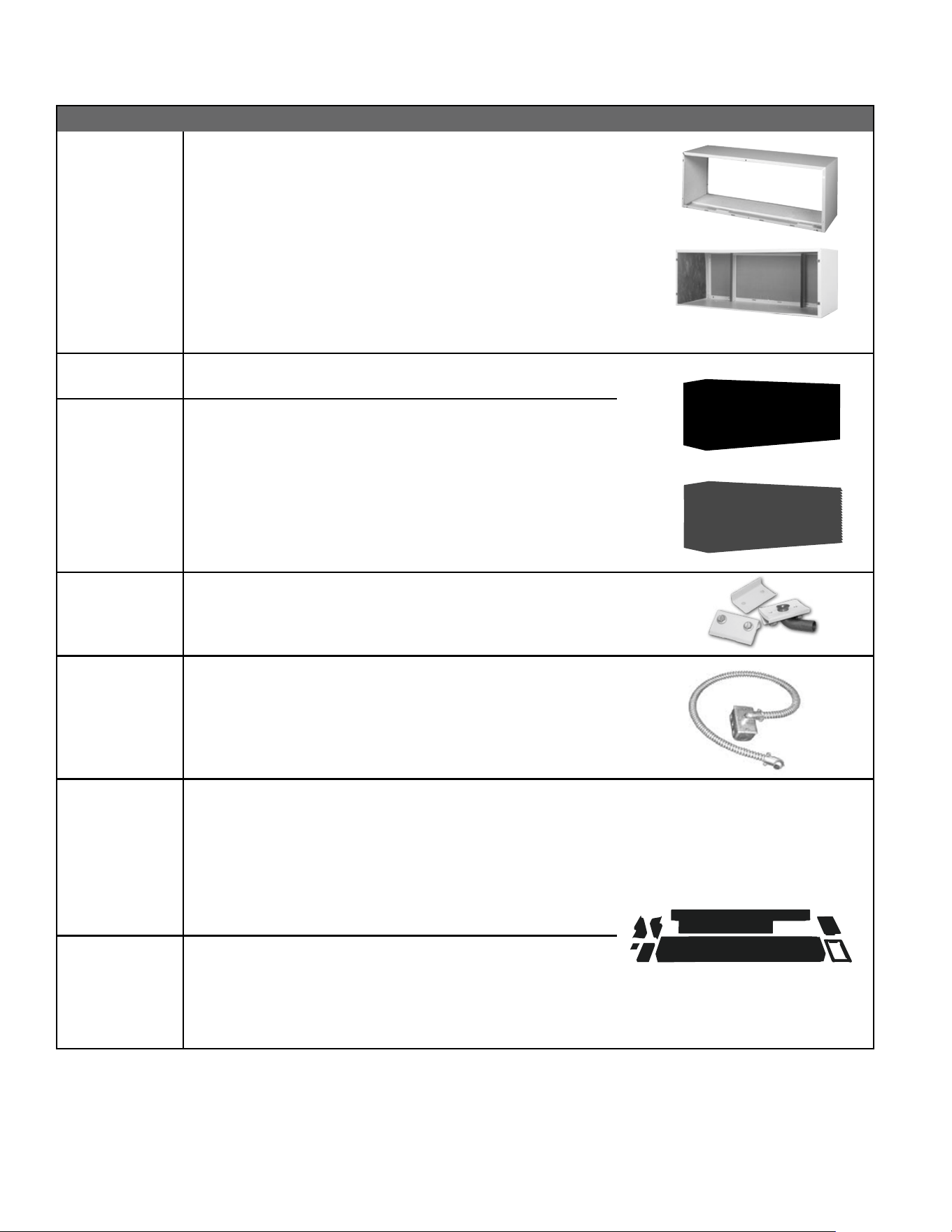
New Construction Accessories
PDXWSA
PDXWSEXT18
PDXWSEXT24
PDXWSEXT
WALL SLEEVE Galvanized zinc coated steel is prepared in an 11-
step process, then powder coated with a polyester nish and cured
in an oven for exceptional durability. The wall sleeve is insulated for
sound absorption and thermal efciency, 16" H x 42" W x 13
3
/4" D.
DEEP WALL SLEEVE For walls up to 17
1
/2" deep.
DEEP WALL SLEEVE For walls up to 23
1
/2" deep.
CUSTOM DEEP WALL SLEEVE One piece extended wall sleeve for walls
from 13
1
/4" to 25
1
/2" deep are available by special order.
PXGA
GRILLE Standard, stamped aluminium, anodized to resist chalking and
oxidation.
PXAA
PXBG
PXSC
ARCHITECTURAL GRILLES C o n s i s t of h e a v y - gauge 6 0 6 3 -T 5 al u m i n um
alloy: 42" W x 16" H x 1
1
/8" D
PXAA – Clear, extruded aluminum
PXBG – Beige acrylic enamel
PXSC – Also available in custom colors.
PXDR10
CONDENSATE DRAIN KIT Attaches to the bottom of the wall sleeve for
internal draining of condensate or to the rear wall sleeve ange for external
draining. Recommended on all units to remove excess condensate.
Packaged in quantities of ten.
PXCJA
CONDUIT KIT WITH JUNCTION BOX Hard wire conduit kit with juncti o n box
for 208/230V and 265V units (subbase not required). Kit includes a
means of quick disconnect for easy removal of the chassis. *Required
for 265V installations.
PDXDAA
LATERAL DUCT ADAPTER Attaches to the Friedrich PTAC/PTHP unit to
direct up to 35% of the total airow to a second room. The unit-mounted
duct plenum features a front-mounted aluminum grille that has two
positions to provide the most optimal air direction. The air may be directed
to either the left or the right of the unit through the supplied 3
1
/2" H x 7" W x
47" L plenum. Plenum may be cut to length by the installer. Kit includes duct
plenum, front grille, 47" duct extension, duct discharge grille, duct end cap
and all necessary mounting hardware.
PDXDEA
LATERAL DUCT EXTENSION Additional 3
1
/2" H x 7" W x 47" L plenum
for use with the LATERAL DUCT ADAPTER. A maximum of 3 duct
extensions total may be used. Note: Ducted airow is reduced as duct
length is increased.
ACCESSORIES
PXAA
PXGA
Deep wall sleeve PDXWSEXT18 shown with weather panel
PDXWSA
38
PDXWSEZ
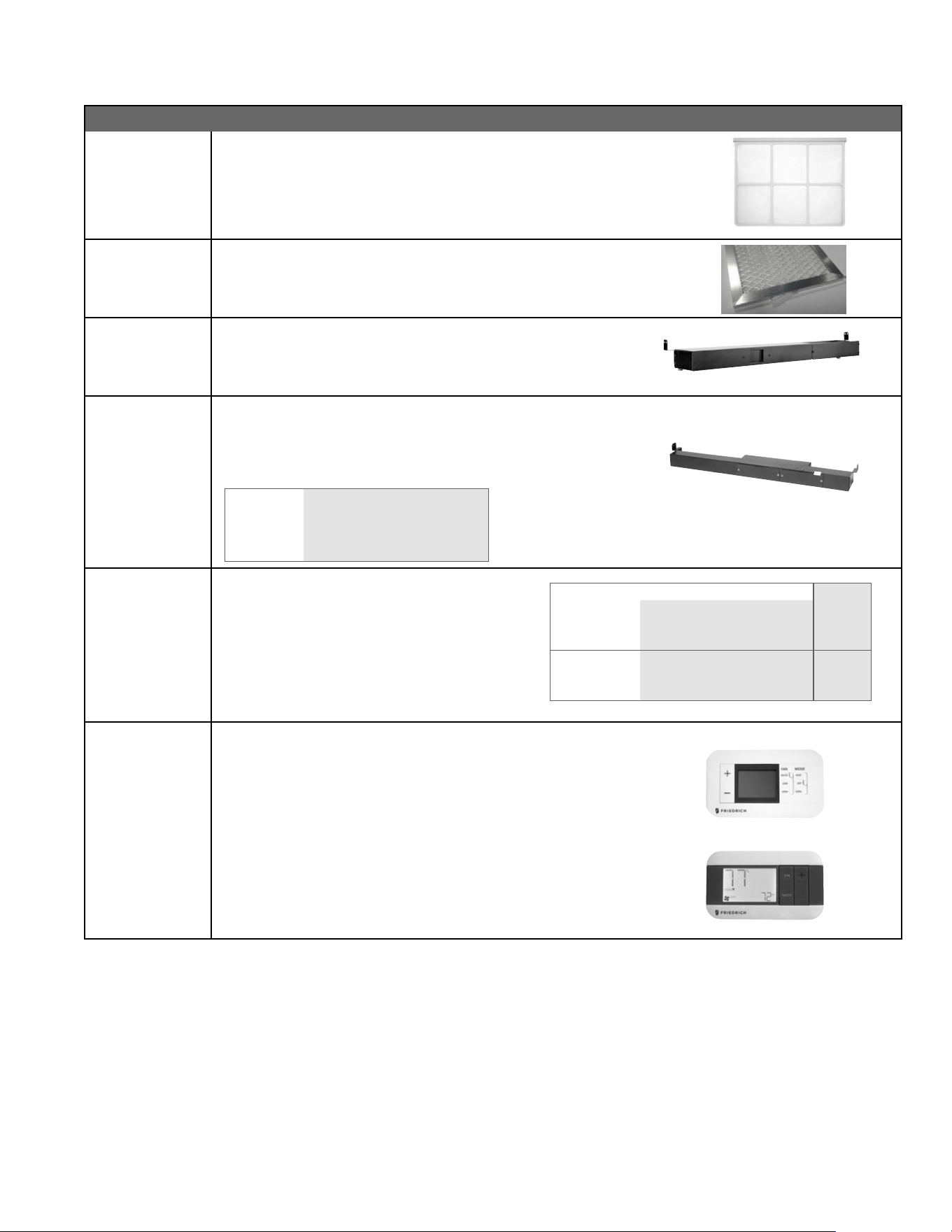
ACCESSORIES
New Construction Accessories
PXFTA REPLACEMENT FILTER PACK These are original equipment return air
lters. They are reusable and can be cleaned by vacuuming, washing, or
blowing out, and are sold in convenient ten-packs. (Two lters per chassis).
PXFAFT10 REPLACEMENT FILTER PACK Merv 8 lters. 10 pack. Each PTAC requires
1 lter.
PXSBA DECORATIVE SUBBASE Provides unit support for walls less than six inches
thick. Includes leveling legs, side filler panels and mounting brackets
for electrical accessories. Accepts circuit breaker, power disconnect
switch, or conduit kit.
PXSB ELECTRICAL SUBBASE Provides unit support for walls less than six inches
thick. Includes leveling legs, side ller panels, mounting brackets, a
plug-in receptacle and field-wiring access. The subbase also includes
electrical knockouts for a power disconnect switch or circuit breaker.
PXSB23020 Electrical Subbase - 230V 15 & 20A
PXSB23030 Electrical Subbase - 230V 30A
PXSB26515 Electrical Subbase - 265V 15A
PXSB26520 Electrical Subbase - 265V 20A
PXSB26530 Electrical Subbase - 265V 30A
PXPCFA POWER CORDS
Universal power cords enable properties to select the
appropriate heater size. Reference the adjacent table
for power cord options
*Cannot be used on PVH09K3FA.
RT7
RT7P
DIGITAL REMOTE THERMOSTATS
RT7 Wired single stage cool, single stage heat for PDE models or single
stage cool, dual stage heat for PDH model thermostat features high/low
fan speed switch. Thermostat is hard wired and can be battery powered or
unit powered. Features backlit display and multiple conguration modes.
For use on Friedrich PTACs and Vert-I-Paks.
RT7P Wired, programmable single stage cool, single stage heat for PDE
models or single stage cool, dual stage heat for PDH model thermostat
features high/low fan speed switch. Thermostat is hard wired and can be
battery powered or unit powered. Features backlit display and multiple
conguration modes. For use on Friedrich PTACs and Vert-I-Paks.
Length
PXPCFA23015 LCDI 230V 15A Cord - 2.5 kW 67 in.
PXPCFA23020 LCDI 230V 20A Cord - 3.5 kW 67 in.
PXPCFA23030* LCDI 230V 30A Cord - 5.0 kW 67 in.
PXPCFA26515 Non-LCDI 265V 15A Cord - 2.5 kW 27 1/2 in.
PXPCFA26520 Non-LCDI 265V 20A Cord - 3.5 kW 27 1/2 in.
PXPCFA26530* Non-LCDI 265V 30A Cord - 5.0 kW 27 1/2 in.
39
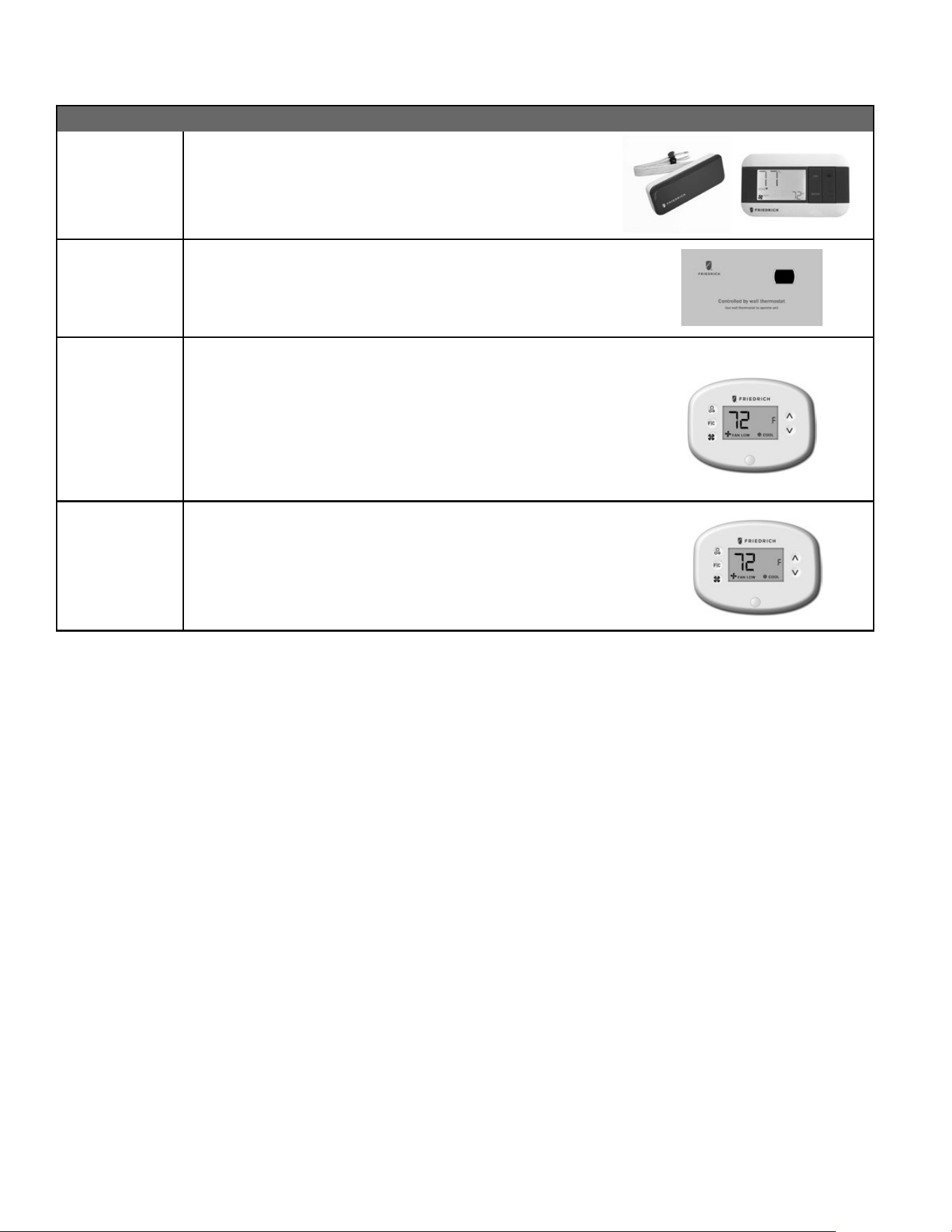
New Construction Accessories
WRT2 WIRELESS DIGITAL REMOTE THERMOSTAT Single stage cool, single
stage heat for PDE models or single stage cool, dual stage heat for PDH
model thermostat features high/low fan speed switch. Thermostat is
wireless and is battery powered. Features backlit display and multiple
conguration modes. For use on Friedrich PTACs and Vert-I-Paks.
PDXRTB REMOTE THERMOSTAT ESCUTCHEON KIT This kit contains ten es cutcheons
that can be placed over the factory control buttons when a remote wall
mounted thermostat is used. The escutcheon directs the guest to the wall
thermostat for operation and retains the LED window to display error codes
and diagnostic information.
EMRT2
EMWRT2
ENERGY MANAGEMENT THERMOSTATS
EMRT2
Wired thermostat with occupancy sensor.
EMWRT2
Wireless thermostat with occupancy sensor.
EMOCT EMRAF EMRHCF
Online connection kit. Remote access fee. Remote humidity control fee.
VRPXEMRT2
(Preferred
FreshAire
Thermostat)
VRPXEMWRT2
Wired and wireless thermosat and occupancy sensor 12v. Full inverter control.
Designed to maximize features and benets of FreshAire system.
Wireless wall controller and occupancy sensor-12v. Full inverter control.
Designed to maximize features and benets of FreshAire system.
*NOTE: The FreshAire PTAC must be paired with wall controller VRPXEMRT2 or VRPXEMWRT2 to operate as a fully variable speed unit.
When used with other compatible thermostats, the unit will operate at multiple speeds in either cooling or heating mode.
ACCESSORIES
40
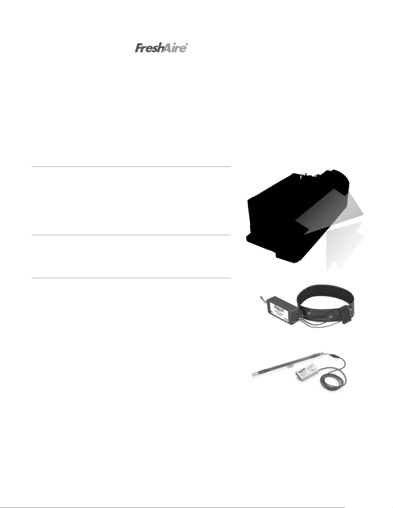
FreshAire
®
Make Up Air (MUA) & Filtration
Award-winning FreshAire MUA system helps achieve ASHRAE 62.1-2013 require-
ments, and brings up to 52 CFM of conditioned, MERV 8 filtered, outside air into
the space. Patented FreshAire technology uses the Precision Inverter compressor
and main cooling system to optimize temperature and humidity level of incoming
air while MERV 8 filtration traps particles and pollutants.
Standard on FreshAire PTAC
FreshAire
®
Purier APWM1
FreshAire Purifier by iWaves features needlepoint bi-polar ionization to address
any mold, bacteria, virus, allergens, and VOC's that may be in your air stream to
ensure delivery of healthy, clean, purified air.
Friedrich
®
UV UVT1
Germicidal UV light kits have been tested and certified for use on Friedrich
PTACs. The UV kit can be installed on the fan coil and is designed to disinfect
surfaces and the air as it circulates through the ventilation system. UV light can
kill airborne bacteria, viruses, mold, reduce maintenance costs and extend the
life of an HVAC system
Friedrich PTAC with
The COVID-19 global pandemic transformed the way the lodging industry meets the comfort and safety needs for guests.
As your room air experts, Friedrich remains committed to improving guest comfort and safety with our newest innovation,
FreshAire
®
IAQ solutions - a suite of indoor air quality accessories for use with Friedrich Air Conditioners, all with one dedicated purpose
- healthy indoor air. FreshAire® IAQ solutions incorporate ASHRAE-recommended protocol* to address indoor air quality and airborne
transmissions.
This suite of products include industry-leading air quality technologies such as MERV 13 filtration,UV germicidal light and bi-polar
ionization. Together, they represent a major leap forward in integrated HVAC air purification and rebuilding confidence for indoor
environments.
*Based on ASHRAE Guidance for Building Operations During the COVID-19 Pandemic
Return air
ACCESSORIES
IAQ
41