1
Service Manual
Standard Chassis Models
Using R-32 Refrigerant
PVH12K3FC, PVH12R3FC
9K
12K
94132000_00
PVH09K3FC, PVH09R3FC
Freshaire
®
R-32 Series
PTAC
Packaged Terminal Air
Conditioners & Heat Pumps
THE EXPERTS IN ROOM AIR CONDITIONING

2
Table of Contents
INTRODUCTION 4
Important Safety Information 4
Personal Injury Or Death Hazards 5
Operation of Equipment in During Construction 8
Typical Unit Components and Dimensions 8
Model Number Reference Guide 9
Serial Number Reference Guide 9
Product Features 10
SPECIFICATIONS 12
General Specifications 12
Electrical Data 15
OPERATION 18
Function and Control 18
Advanced Functions 22
Advanced Settings 22
Memory Function 23
FD Control (front-desk control) & 24V REMOTE THERMOSTAT 23
Protection Functions 24
System Configuration Fresh Air Vent Control 26
Digital Control User Input Configuration 29
Settings- Detailed Configurations 30
General Knowledge Sequence Of Refrigeration 31
Refrigerant System Diagram 32
ROUTINE MAINTENANCE 33
INSTALLATION 34
PTAC Installation Recommendations 34
Wall Sleeve Installation Instructions (PDXWS) 35
Alternate Wall Installations 36
PXDR10 Drain Kit Installation 39
External Drain 40
PXGA Standard Grille 41
Remote Control Thermostat Installation 43
Front Desk Control Terminal 44
Final Inspection & Start-up Checklist 45
TROUBLESHOOTING 46
Basic Troubleshooting 46
Error code and solutions 48
Unit Does Not Operate 50
Check Heater Coil 52
Check Electric Heater Control 53
Check Thermistors 54
UNIT DISASSEMBLY AND COMPONENT REPLACEMENT 55
Remove Chassis 55
Remove User Interface 56
Open Electrical Control Box 57
Remove Main PCB (logic) Board 57
Remove Power Cord 58
Remove Power PCB 59
Remove IPM PCB (Inverter Board) 60
Remove Blower Wheel 61
Remove Blower Wheel Motor 64
Remove Heating Element 66
Remove Fresh air Components 67
Remove Outdoor Fan 69
Remove Reversing valve Solenoid 72
COMPONENT TESTING 73
Hermetic Components Check 73
Reversing Valve Description And Operation 74
Checking the Reversing Valve 74
Checking The Reversing Valve Solenoid 74
Compressor Checks 75
Check Indoor and Outdoor Fan Motors 77
Check Outdoor Fan Motor Capacitor 78
Main PCB (logic) Board Connector Identification 79
TABLE OF CONTENTS

3
Power PCB (Power Board) Connector Identification 80
R-32 SEALED SYSTEM REPAIR 81
General Information 81
Required Equipment 83
Refrigerant Removal, Recovery, and Evacuation 84
Component Replacement/Brazing 85
Refrigerant Charging 86
Compressor Replacement 87
Compressor Replacement -Special Procedure in Case of Compressor Burnout 88
Replace The Reversing Valve 89
WIRING DIAGRAM 90
APPENDIX 96
Accessories 91
Interactive Parts Viewer 91
Limited Warranty 91
Appendix 1 Reference Sheet Of Celsius And Fahrenheit 96
Appendix 2 Resistance Table Of Thermistors (5k) 97
Appendix 2 Resistance Table Of Thermistors (50k)(Compressor Discharge Sensor) 99
Friedrich Authorized Parts Depots 100
TABLE OF CONTENTS
4
Important Safety Information
INTRODUCTION
The information in this manual is intended for use by a qualified technician who is familiar with the safety procedures required for installation and
repair, and who is equipped with the proper tools and test instruments required to service this product.
Installation or repairs made by unqualified persons can result in subjecting the unqualified person making such repairs as well as the persons being
served by the equipment to hazards resulting in injury or electrical shock which can be serious or even fatal.
Maintenance is the responsibility of the owner. Failure to properly maintain or repair equipment may result in personal injury and/or various types
of property damage (fire, flood, etc.).
Safety warnings have been placed throughout this manual to alert you to potential hazards that may be encountered. If you install or perform service
on equipment, it is your responsibility to read and obey these warnings to guard against any bodily injury or property damage which may result to
you or others.
Due to continuing research in new energy-saving technology, all information in this manual is subject to change
without notice.
This service manual is designed to be used in conjunction with the installation and operation manuals provided
with each air conditioning system.
This service manual was written to assist the professional service technician to quickly and accurately diagnose
and repair malfunctions.
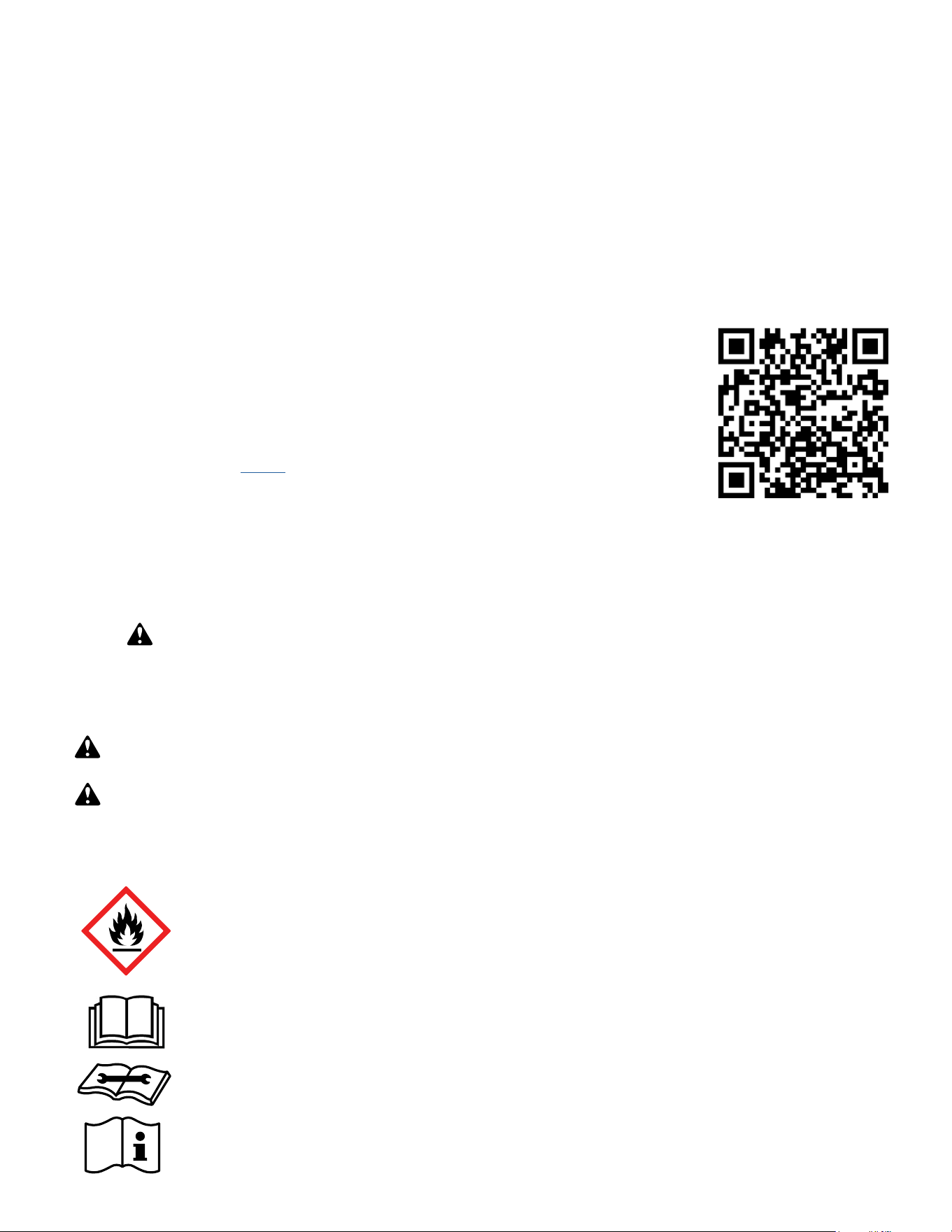
Installation procedures are not given in this manual. They are given in the Installation/Operation manual which
can be acquired on the Friedrich website. Click the Link or scan the QR code to be directed to the Professional
page where you can locate our technical literature.
This symbol indicates that this appliance uses a flammable refrigerant. If the refrigerant is leaked and is exposed to an
external ignition source, there is a risk of fire.
This symbol indicates that the Operation Manual should be read carefully.
This symbol indicates that service personnel should be handling this equipment with reference to the installation manual.
This symbol indicates that information is available such as the Installation and Operation manual, or the Service Manual.
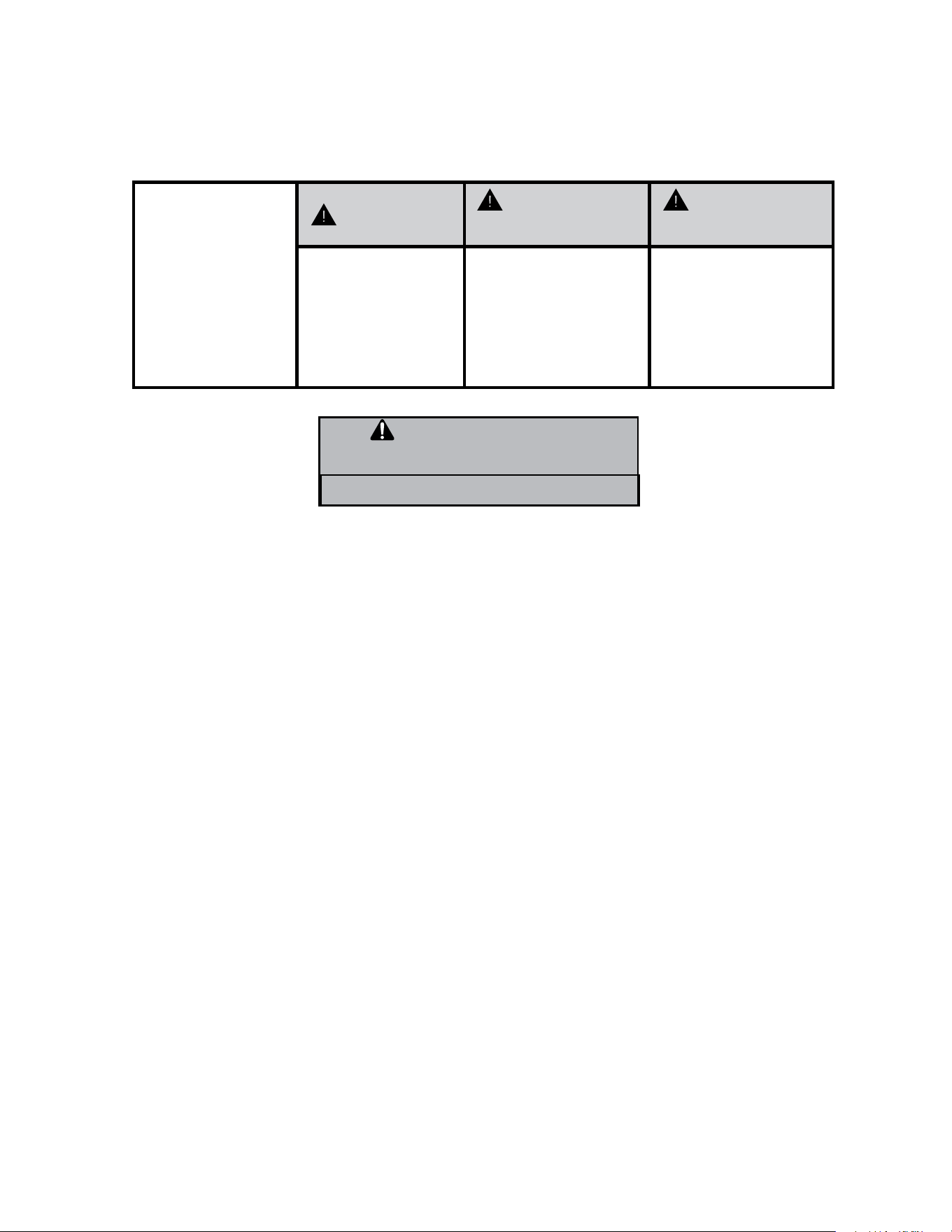
SAFETY IS IMPORTANT
We have provided many important safety messages in this manual and on your appliance. Always read and obey all safety messages.
Indicates a hazard which, if not avoided, can result in severe personal injury or death and damage to product or other
property.
Indicates a hazard which, if not avoided, can result in personal injury and damage to product or other property.
All safety messages will tell you what the potential hazard is, tell you how to reduce the chance of injury, and tell you
what will happen if the instructions are not followed.
NOTICE
CAUTION
WARNING
All safety messages will follow the safety alert symbol with the word “WARNING” or “CAUTION”. These words mean:
This is a safety Alert symbol. This symbol alerts you to potential hazards that can kill or hurt you and others.
Indicates property damage can occur if instructions are not followed.
5
INTRODUCTION
Personal Injury Or Death Hazards
WARNING
:
The manufacturer’s warranty does not cover any damage or defect to the air conditioner caused by the attachment
or use of any components, accessories or devices (other than those authorized by the manufacturer) into, onto or in conjunction with the air
conditioner. You should be aware that the use of unauthorized components, accessories or devices may adversely affect the operation of the
air conditioner and may also endanger life and property. The manufacturer disclaims any responsibility for such loss or injury resulting from
the use of such unauthorized components, accessories or devices.
WARNING
:
This appliance is not intended for use by persons (Including children) with reduced physical, sensory or mental
capabilities, or lack of experience and knowledge, unless they have been given supervision or instruction concerning use of the appliance by
a person responsible for their safety.
Children should be supervised to ensure that they do not play with the appliance.
WARNING
:
The maximum altitude for this appliance is 2,000 meters(6,562 feet).
Do not use above 2,000 meters(6,562 feet).
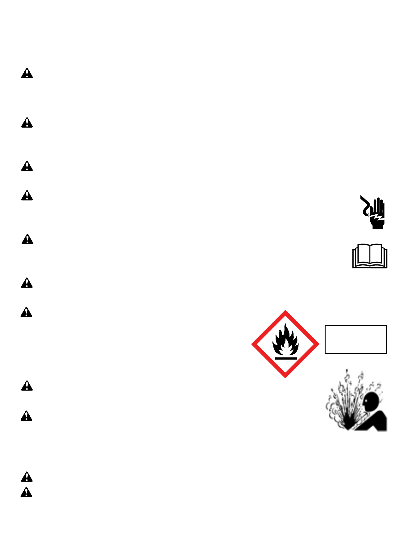
WARNING: Electrical Shock Hazard
Disconnect all power to the unit before starting maintenance. All electrical connections and wiring MUST be installed by a qualified
electrician and conform to the National Code and all local codes which have jurisdiction. Failure to do so can result in property
damage, severe electrical shock or death.
WARNING:
Read Installation Manual
Read this manual thoroughly prior to equipment installation or operation. It is the installer’s responsibility to properly apply
and install the equipment. Installation must be in conformance with the NFPA 70-2023 national electric code or current edition,
International Mechanic code 2021 or current edition, and any other local or national codes.
WARNING:
Safety First
Do not remove, disable, or bypass this unit’s safety devices. Doing so may cause fire, injuries, or death.
WARNING: This Product uses R-454B Refrigerant
Do not use means to accelerate the defrosting process or to clean, other than those
recommended by the manufacturer.
The appliance shall be stored in a room without continuously operating ignition sources
(for example: open flames, an operating gas appliance or an operating electric heater.
Do not pierce or burn.
Be aware that refrigerants may not contain an odor.
WARNING:
Refrigeration System under High pressure
Do not puncture, heat, expose to flame or incinerate. Only certified refrigeration technicians should service this
equipment. R454B systems operate at higher pressures than R22 equipment. Appropriate safe service and
handling practices must be used.
CAUTION:
Do Not Operate Equipment During Active Stages Of
Construction
To ensure proper operation, Friedrich requires that all equipment is not operated during active construction phases. This includes active stages
of completing framing, drywalling, spackling, sanding, painting, flooring, and moulding in the equipment’s designated conditioning space. The
use of this equipment during construction could result in premature failure of the components and/or system and is in violation of our standard
warranty guidelines. The operation of newly installed equipment during construction will accelerate the commencement and/or termination of
the warranty period.
WARNING:
Keep all air circulation and ventilation openings free from obstruction.
WARNING:
The unit should not be in contact with any equipment that will transmit vibration to the unit. Any excessive vibration or
pulsation to the unit could result in damage to the refrigerant tubing.
Refrigerant
Safety Group
A2L
6
SAFETY
FIRST
WARNING
AVERTISSE-
MENT
ADVERTEN-
CIA
Do not remove, disable or
bypass this unit’s safety
devices. Doing so may
cause fire, Doing so may
cause fire, injuries, or
death.
Ne pas supprime, désactiver
ou contourner cette l´unité
des dispositifs de sécurité,
faire vous risqueriez de
provoquer le feu, les
blessures ou la mort.
No eliminar, desactivar o
pasar por alto los dispositi-
vos de seguridad de la
unidad. Si lo hace podría
producirse fuego, lesiones o
muerte.
ELECTRICAL HAZARDS:
• Unplug and/or disconnect all electrical power to the unit before performing inspections, maintenance, or service.
• Make sure to follow proper lockout/tag out procedures.
• Always work in the company of a qualified assistant if possible.
• Capacitors, even when disconnected from the electrical power source, retain an electrical charge potential capable of causing electric
shock or electrocution.
• Handle, discharge, and test capacitors according to safe, established, standards, and approved procedures.
• Extreme care, proper judgment, and safety procedures must be exercised if it becomes necessary to test or troubleshoot equipment
with the power on to the unit.
• Do not spray water on the air conditioning unit while the power is on.
• Electrical component malfunction caused by water could result in electric shock or other electrically unsafe conditions when the power
is restored and the unit is turned on, even after the exterior is dry.
• Use air conditioner on a single dedicated circuit within the specified amperage rating.
• Use on a properly grounded outlet only.
• Do not cut or modify the power supply cord or remove the ground prong of the plug.
• Never operate the unit on an extension cord.
• Follow all safety precautions and use proper and adequate protective safety aids such as: gloves, goggles, clothing, properly insulated
tools, and testing equipment etc.
• Failure to follow proper safety procedures and/or these warnings can result in serious injury or death.
INTRODUCTION
Personal Injury Or Death Hazards
WARNING
ALWAYS USE INDUSTRY STANDARD PERSONAL PRO-
TECTIVE EQUIPMENT (PPE)

7
• REFRIGERATION SYSTEM REPAIR HAZARDS:
• Use approved standard refrigerant recovering procedures and equipment to relieve high pressure before opening system for repair.
• Do not allow liquid refrigerant to contact skin. Direct contact with liquid refrigerant can result in minor to moderate injury.
• Be extremely careful when using an oxy-acetylene torch. Direct contact with the torch’s flame or hot surfaces can cause serious burns.
• Make certain to protect personal and surrounding property with fire proof materials and have a fire extinguisher at hand while using a
torch.
• Provide adequate ventilation to vent off toxic fumes, and work with a qualified assistant whenever possible.
• Always use a pressure regulator when using dry nitrogen to test the sealed refrigeration system for leaks, flushing etc.
• MECHANICAL HAZARDS:
• Extreme care, proper judgment and all safety procedures must be followed when testing, troubleshooting, handling, or working around
unit with moving and/or rotating parts.
• Be careful when, handling and working around exposed edges and corners of the sleeve, chassis, and other unit components especially
the sharp fins of the indoor and outdoor coils.
• Use proper and adequate protective aids such as: gloves, clothing, safety glasses etc.
• Failure to follow proper safety procedures and/or these warnings can result in serious injury or death.
• PROPERTY DAMAGE HAZARDS
• FIRE DAMAGE HAZARDS:
• Read the Installation/Operation Manual for the air conditioning unit prior to operating.
• Use air conditioner on a single dedicated circuit within the specified amperage rating.
• Connect to a properly grounded outlet only.
• Do not remove ground prong of plug.
• Do not cut or modify the power supply cord.
• Do not use extension cords with the unit.
• Be extremely careful when using acetylene torch and protect surrounding property.
• Failure to follow these instructions can result in fire and minor to serious property damage.
• WATER DAMAGE HAZARDS:
• Improper installation, maintenance or servicing of the air conditioner unit can result in water damage to personal items or property.
• Insure that the unit has a sufficient pitch to the outside to allow water to drain from the unit.
• Do not drill holes in the bottom of the drain pan or the underside of the unit.
• Failure to follow these instructions can result in damage to the unit and/or minor to serious property damage.
INTRODUCTION
Personal Injury Or Death Hazards
8
INTRODUCTION
Operation of Equipment in During Construction
• OPERATION OF EQUIPMENT MUST BE AVOIDED DURING CONSTRUCTION PHASES WHICH WILL PRODUCE AIR-
BORNE DUST OR CONTAMINATES NEAR OR AROUND AIR INTAKE OPENINGS:
• Wood or metal framing;
• Dry walling or sheathing,
• Spackling or applying joint compound.
• Sanding or grinding.
• Moulding or trim work.
NOTICE
Operating the equipment during any phase of active construction
noted above can void the equipment’s warranty, also leading to poor
performance and premature failure
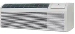
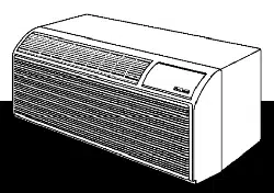
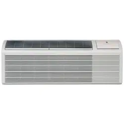
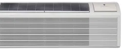
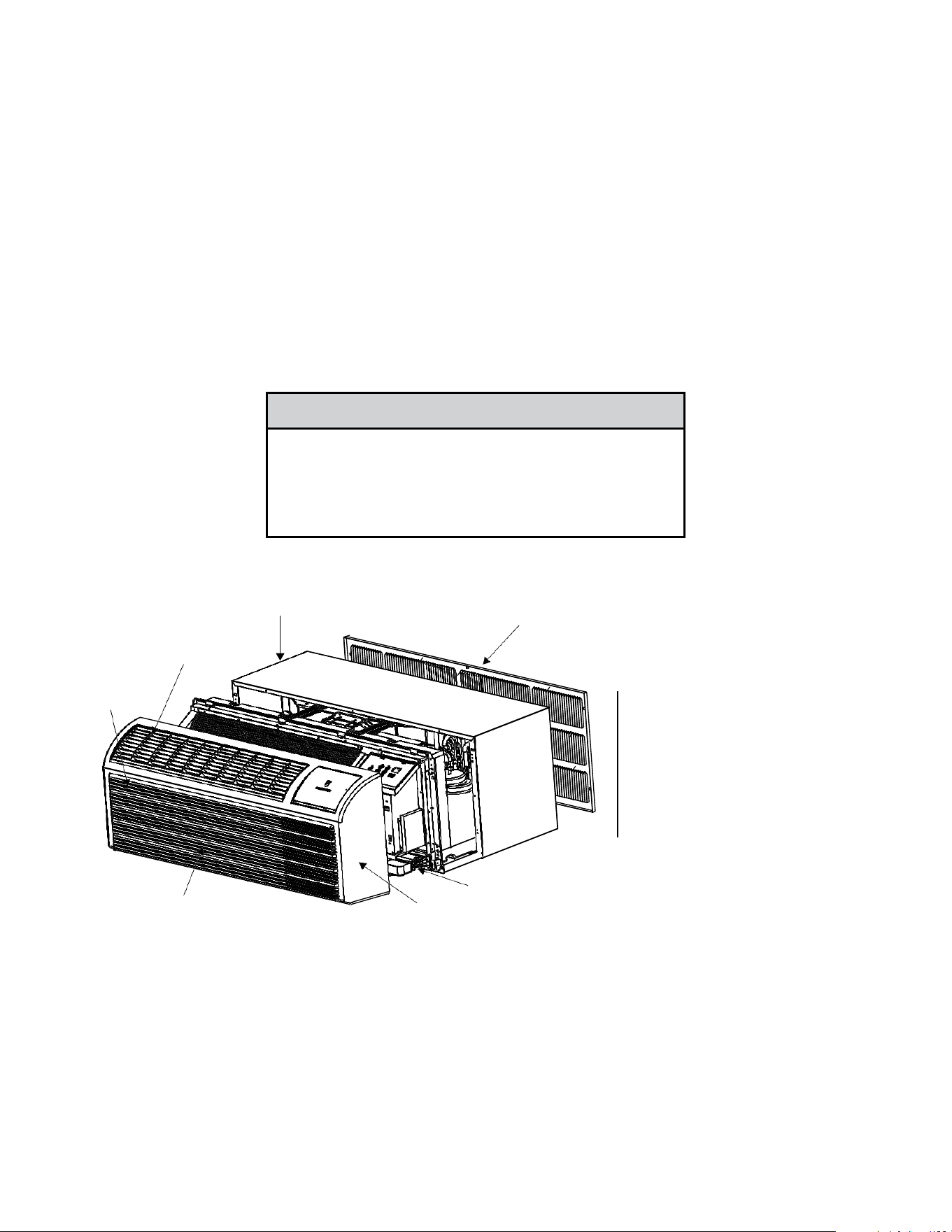
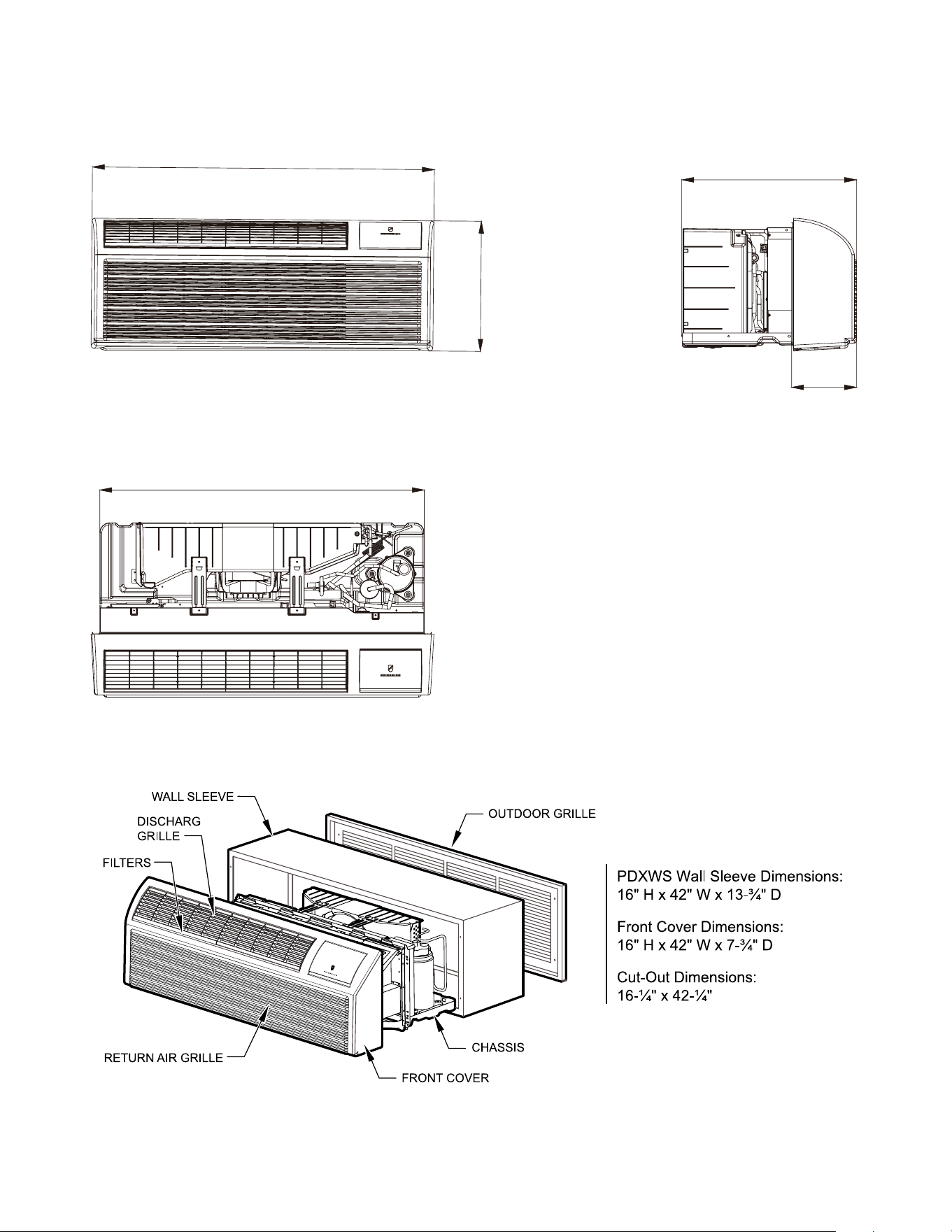
Typical Unit Components and Dimensions
WALL SLEEVE
FILTERS
DISCHARGE GRILLE
RETURN AIR GRILLE
OUTDOOR GRILLE
PDXWS Wall Sleeve
Dimensions: 16" H x 42" W x
13-¾" D
Front Cover Dimensions:
16" H x 42" W x 7-¾" D
Cut-Out Dimensions:
16-¼"x42-¼"
9
INTRODUCTION
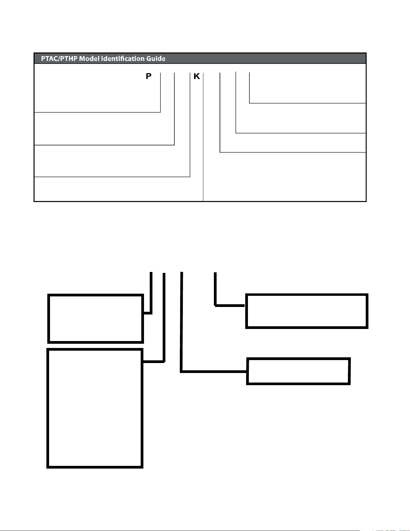
Model Number Reference Guide
IMPORTANT: It will be necessary for you to accurately identify the unit you are servicing, so you can be certain of a proper diagnosis
and repair.
Figure 103
V
H
09
3F
MODEL NUMBER
Series
PV = Friedrich Digital PTAC
Nominal Capacity
Engineering Digit
System
E=Cooling with Electric Heat
H= Heat Pump with Auxiliary Electric Heat
DesignSeries
Chassis
F= FreshAire
07 = 7,000 Btuh
09= 9,000 Btuh
12 = 12,000 Btuh
15 = 15,000 Btuh
Nominal Heater Size (230V or 265V)
3=3kW
Voltage
K=230/208V-1 Ph.-60Hz.
R = 265V - 1 Ph. - 60 Hz.
C
Serial Number Reference Guide
YEAR OF MANUFACTURE
24 = 2024 27 = 2027
25 = 2025 28 = 2028
26 = 2026 29 = 2029
MONTH OF MANUFACTURE
01 = JANUARY
02 = FEBRUARY
03 = MARCH
04 = APRIL
05 = MAY
06 = JUNE
07 = JULY
08 = AUGUST
09 = SEPTEMBER
10 = OCTOBER
11 = NOVEMBER
12 = DECEMBER
MANUFACTURING LOCATION
NUMERIC SEQUENCE
FIRST UNIT OF EACH MONTH = 00001
17 12 M 00001
Figure 104
10
INTRODUCTION
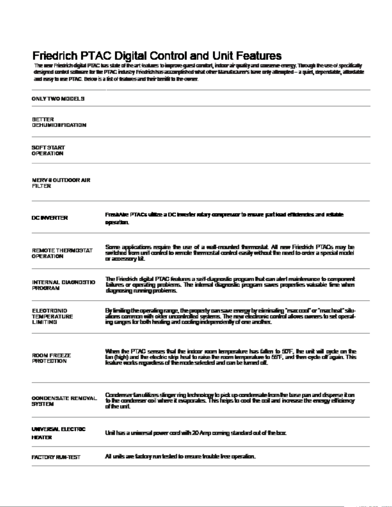
Product Features
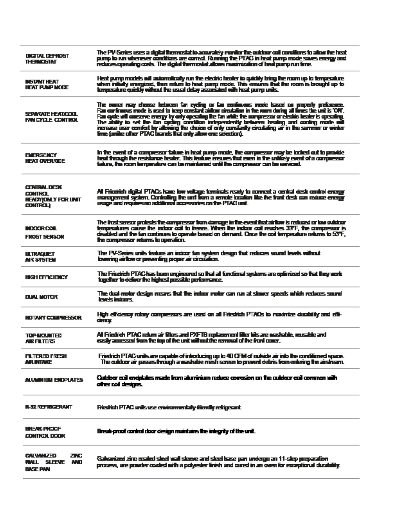
11
INTRODUCTION
Product Features
12
SPECIFICATIONS
General Specifications
Specification Unit PVH09K3FC PVH12K3FC PVH09R3FC PVH12R3FC
Power supply (V-Ph-
Hz)
230V-208V/1Ph/60Hz 230V-208V/1Ph/60Hz 265V/1Ph/60Hz 265V/1Ph/60Hz
Operation Volt Range V 253–187 253–187 292–239 292–239
Cooling Capacity - Test Data BTU 10240/10190 12470/12430 10150 12430
Cooling Capacity - Rated BTU 9800/9700 12000/11800 9800 12000
Reverse Cooling Capacity Min./
Max.
BTU 5800-12000 6100-15500 5800-12000 6100-15500
Cooling Watts - Test Data W 818/822 1033/1040 819 1022.7
Cooling Watts - Rated W 815/805 1040/1025 815 1040
EER - Test Data 12.52/12.39 12.08/11.94 12.4 12.2
EER - Rated 12.0/12.0 11.5/11.5 12.0/12.0 11.5
Heating Capacity - Test Data BTU 8883/8839 11935/11875 9060 11980
Heating Capacity - Rated BTU 8500/8400 11700/11700 8500 11700
Heating Watts - Test Data W 711/701 891.2/885.9 733 886
Heating Watts - Rated W 710/700 940/940 710 940
Reverse Heating Capacity Min./
Max.
BTU 5500-10800 6000-14000 5500-10800 6000-14000
COP - Test Data 3.66/3.7 3.93/3.93 3.6 4.0
COP - Rated 3.51/3.51 3.65/3.65 3.5 3.7
Rated Moisture Removal
(pints/hour)
P/H 1.4 1.9 1.2 2.4
Sensible Heat Ratio 77.3% 77.4% 78% 78.6%
Reverse Cooling Current A 3.9/3.6 4.9/4.5 3.1 3.9
Reverse Heating Current A 3.4/3.1 4.5/4.1 2.7 3.5
Power Factor 1.0 1.0 0.9 1.0
Electric Heating
Capacity (230/208V)
Btu/h 12000/9900 17000/13900 12000 12000
Electric Heating
Power input (230/208V)
W 3550/2900 5050/4135 3550 3550
Electric Heating
Rated current (230/208V)
A 6.1 19.87/21.95 13.4 13.4
Refrigerant Charge Amount Oz 24.3 27.2 24.3 24.3
Compressor brand GMCC GMCC GMCC GMCC
Compressor LRA A / / / /
Compressor RLA A 3.2 4.1 2.8 3.5
Indoor Motor Type DC DC DC DC
Indoor Fan Motor Power HP 0.0 0.0 0.0 0.0
Indoor Fan Motor RLA A 0.4 0.4 0.4 0.4
Outdoor Motor Type AC AC AC AC
Outdoor Fan Motor Power HP 0.1 0.1 0.1 0.1
Outdoor Fan Motor RLA A 0.4 0.4 0.4 0.4
Indoor Fan CFM, High CFM 700 750 700 780
Indoor Fan CFM, Low CFM 535 560 535 560
MUA Fan CFM CFM UP TO 52 UP TO 52 UP TO 52 UP TO 52
Indoor Fan Noise Level(turn on
the fresh air)
dBA 52~54Fan mode 52~55Fan mode 53~54Fan mode 52~55Fan mode
Table 201
13
Specification Unit PVH09K3FC PVH12K3FC PVH09R3FC PVH12R3FC
Indoor Fan Noise Level(turn off
the fresh air)
dBA 41~49 Fan mode 44~53 Fan mode 44~49Fan mode 44~52Fan mode
Indoor Fan Noise Level(turn on
the fresh air)cooling mode
dBA 55~56(cooling mode) 54~56(cooling mode) 54~55(cooling mode) 55~56(cooling mode)
Indoor Fan Noise Level(turn off
the fresh air)cooling mode
dBA 55~56(cooling mode) 51~55(cooling mode) 52~53(cooling mode) 53~56(cooling mode)
Indoor Fan Noise Level(turn on
the fresh air)heating mode
dBA 54~55(heating mode) 54~56(heating mode) 55~56(heating mode) 55~57(heating mode)
Indoor Fan Noise Level(turn off
the fresh air)heating mode
dBA 52~54(heating mode) 52~55(heating mode) 52~53(heating mode) 54~56(heating mode)
Outdoor Fan Noise Level
(turn on the fresh air)
dBA 68 70 68 68
Outdoor Fan Noise Level
(turn off the fresh air)
dBA 68 70 67 67
Outdoor operating temperature
range, cooling
F 60.8 ~ 89.6 60.8 ~ 89.6 60.8 ~ 89.6 60.8 ~ 89.6
Outdoor operating temperature
range, heating
F 32 ~ 86 32 ~ 86 32 ~ 86 32 ~ 86
Dimensions, HxWxD inch 41 31/32*21 1/16*16 1/16 41 31/32*21 1/16*16 1/16
Net Weight lbs 120 136 120 136
Gross Weight lbs 141 157 141 157
SPECIFICATIONS
General Specications
Table 201
14
SPECIFICATIONS
Figure 202 ( Chassis Specs)
Unit:inch
21 1/2
10
42
40
16
E
Figure 203 (Typical Unit Components and Dimensions)
15
SPECIFICATIONS
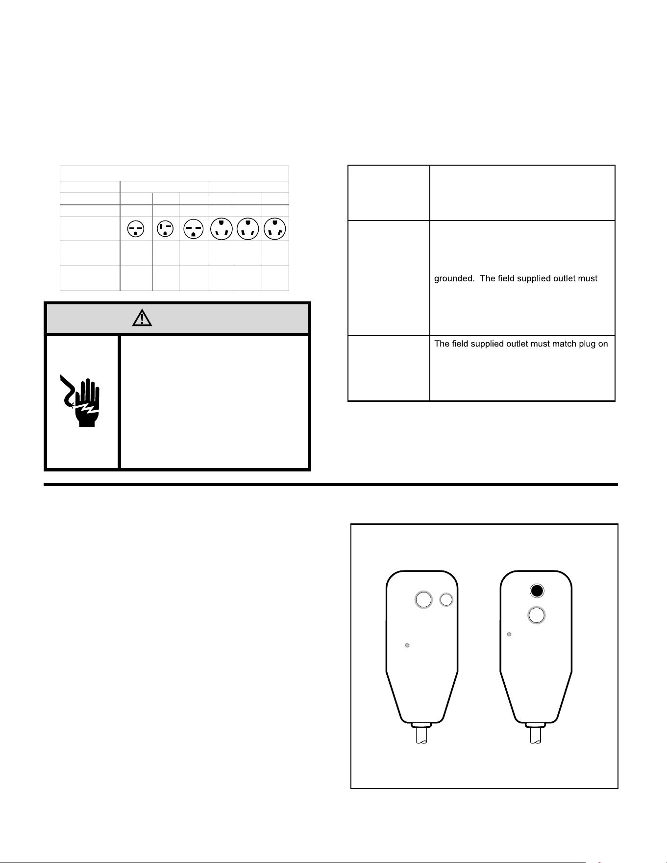
Electrical Data
GN I NRA W
15/20A LCDI Device 30A LCDI Device
TEST BEFORE EACH USE
NO TTUB TESER SSERP . 1
2. PLUG LCDI INT O POWER
E LCA TP ECER
, NO T TUB TS ET SSERP . 3
RESET BUTTON SHOULD
POP UP
4. PRESS , N O TTUB TSET
FOR USE
DO NOT T SET EVOBA F I ESU
SL I AF
WHEN GREEN LIGHT IS ON
IT IS WORKING PROPERLY
RESET
TEST
GN I NRA W
TEST BEFORE EACH USE
NO TTUB T ESER SSERP . 1
2. PLUG LCDI INT O POWER
E L CA T PECER
, NO T TUB TS ET SSERP . 3
RESET BUTTON SHOULD
POP UP
, NO T TUB TS ET SSERP . 4
FOR USE
DO NOT T SET EVOBA F I ESU
SL I AF
WHEN GREEN LIGHT IS ON
IT IS WORKING PROPERLY
RESET
TEST
FRP014
FUSE/CIRCUIT
BREAKER
Use ONLY type and size fuse or HVAC/R
circuit breaker indicated on unit’s rating
plate. Proper current protection to the unit
is the responsibility of the owner. NOTE: A
time delay fuse is provided with 265V units.
GROUNDING
Unit MUST be grounded from branch circuit
through service cord to unit, or through
separate ground wire provided on per-
manently connected units. Be sure that
branch circuit or general purpose outlet is
match plug on service cord and be within
reach of service cord. Refer to Table 1 for
proper receptacle and fuse type. Do NOT
alter the service cord or plug. Do NOT use
an extension cord.
RECEPTACLE
service cord and be within reach of service
cord. Refer to Table 1 for proper receptacle
and fuse type. Do NOT alter the service
cord or plug. Do NOT use an extension
cord.
All Friedrich 230/208V PTAC units are shipped from the factory with a
Leakage Current Detection Interrupter (LCDI) equipped power cord. The
LCDI device meets the UL and NEC requirements for cord connected air
conditioners effective August 2004.
To test your power supply cord:
1. Plug power supply cord into a grounded 3 prong outlet.
2. Press RESET.
3. Press TEST ( listen for click; Reset button trips and pops out).
4. Press and release RESET (listen for click; Reset button latches
and remains in). Check that the green LED indicator is on. The
power supply cord is ready for operation.
NOTE: The LCDI device is not intended to be used as a switch.
Once plugged in the unit will operate normally without the need to reset
the LCDI device.
If the LCDI device fails to trip when tested or if the power supply cord is
damaged it must be replaced with a new supply cord obtained from the
product manufacturer, and must not be repaired.
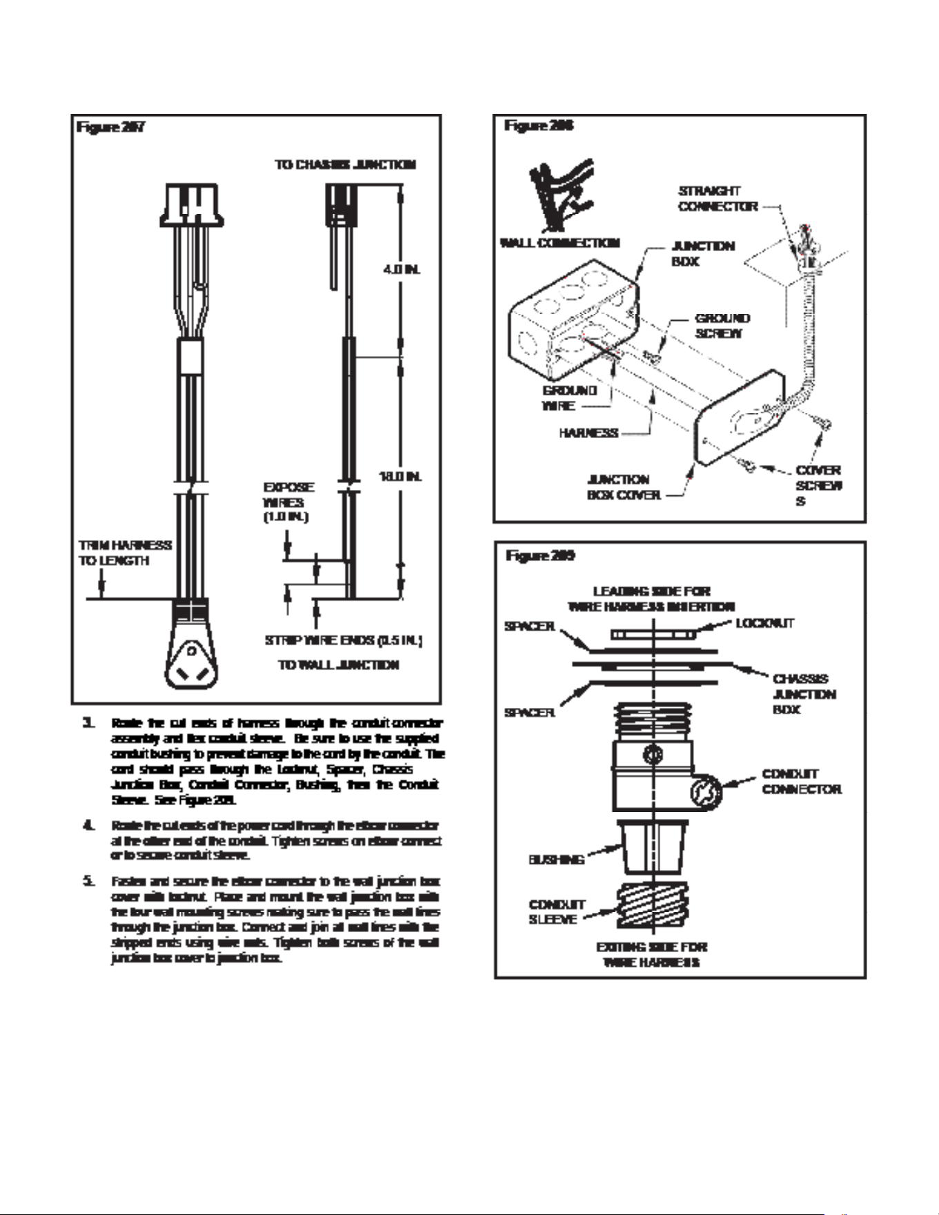
B. Power Cord Information (230/208V models only)
Figure 205
Typical LCDI Devices
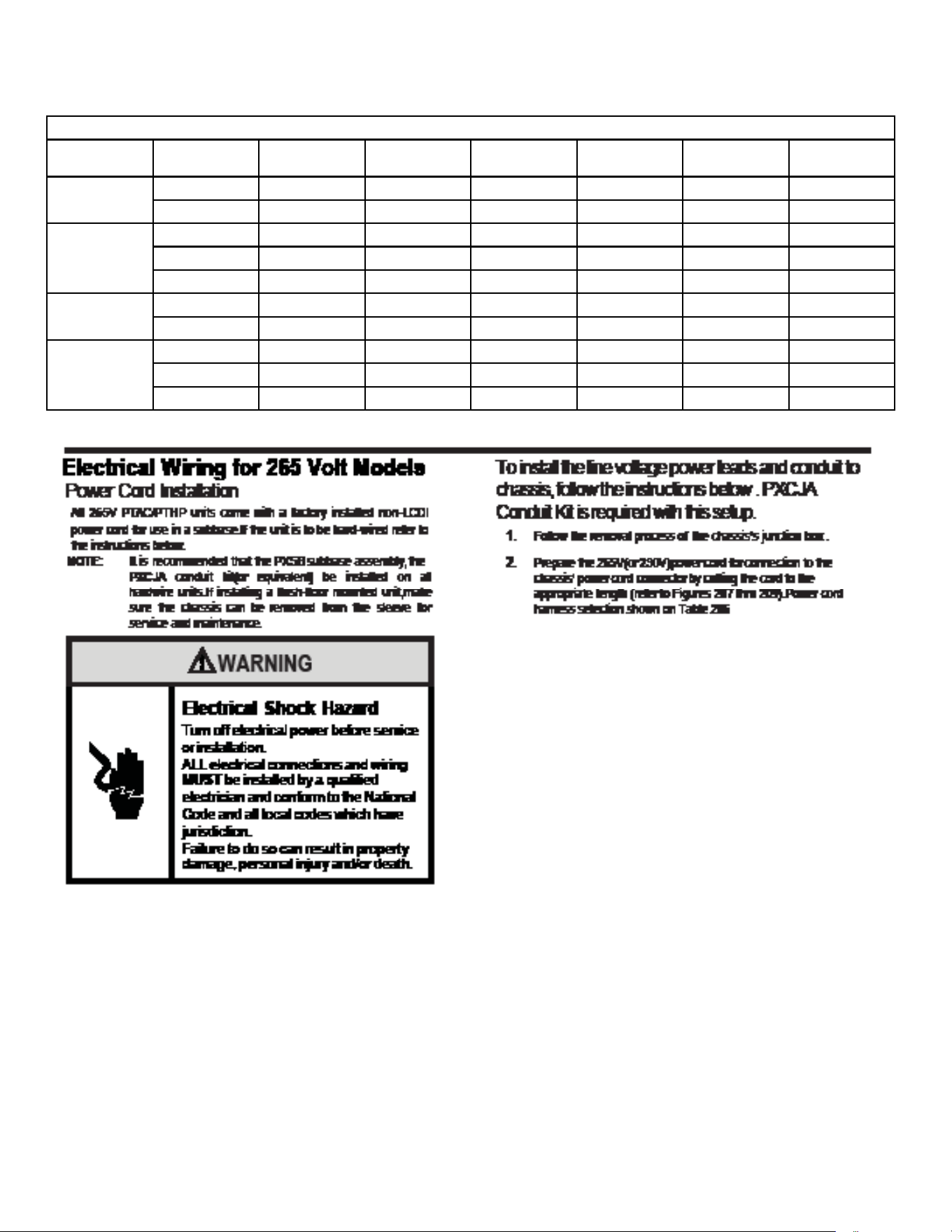
A. Electrical Rating Tables
All 230/208 volt units are equipped with LCDI power cords.
All 265 volt units are equipped with non-LCDI power cords.
NOTE: Use Copper Conductors ONLY. Wire sizes are per NEC, check local codes for overseas applications.
NOTE: Use on single dedicated circuit within specified amperage rating.
WARNING
Electrical Shock Hazard
Turn off electrical power before service
or installation.
ALL electrical connections and wiring
MUST be installed by a qualified
electrician and conform to the National
Code and all local codes which have
jurisdiction.
Failure to do so can result in property
damage, personal injury and/or death.
RECEPTACLES AND FUSE TYPES
Voltage 230V 265V
Amps
15 20 30 15 20 30
Heater Size
2.5 kW 3.5 kW 5.0 kW 2.5 kW 3.5 kW 5.0 kW
Receptacles
NEMA#
Receptacle
6-15R 6-20R 6-30R 7-15R 7-20R 7-30R
NEMA#
Plug
6-15P 6-20P 6-30P 7-15P 7-20P 7-30P
Table 204
16
SPECIFICATIONS
Electrical Data
TABLE 206
MODEL HEATER kW Power Cord Kit Voltage
BRANCH CKT
AMPS
MCA
Watts Receptacle
PVH09K 2.5(optional) PXPCFA23015 230/208 15
13.9 2500
NEMA 6-15r
3.5(default) PXPCFA23020 230/208 20
19.9 3600
NEMA 6-20r
PVH12K 1.5(optional) PXPCFA23015 230/208 15
13.9 2500
NEMA 6-15r
3.5(default) PXPCFA23020 230/208 20
19.9 3600
NEMA 6-20r
5.0(optional) PXPCFA23030 230/208 30
27.5 5000
NEMA 6-30r
PVH09R 2.5(optional) PXPCFA26515 265 15
12.0 2500
NEMA 7-15r
3.5(default) PXPCFA26520 265 20
16.8 3500
NEMA 7-20r
PVH12R 1.5(optional) PXPCFA26515 265 15
7.3 1500
NEMA 7-15r
3.5(default) PXPCFA26520 265 20
16.8 3500
NEMA 7-20r
5.0(optional) PXPCFA26530 265 30
23.8 5000
NEMA 7-30r
17
SPECIFICATIONS
Electrical Data

18
OPERATION
Function and Control
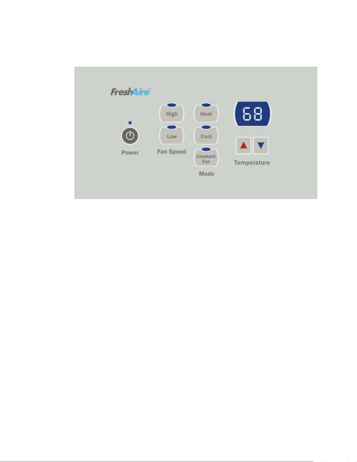
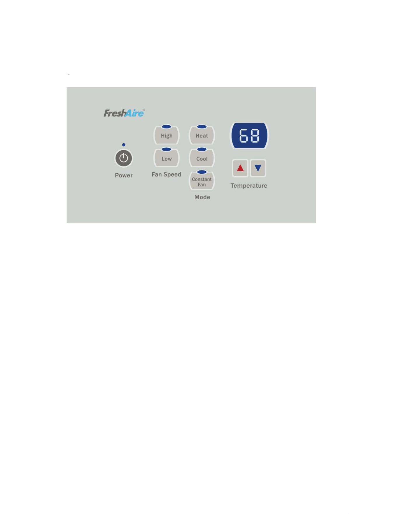
Buttons and Display
1) Buttons
There are ON/OFF, UP, DOWN, HEAT, COOL, CONSTANT FAN and fan speed of HIGH, LOW, AUTO buttons.
1. ON/OFF: Press to turn power on or off to the unit.
2. COOL, HEAT: choose the mode of operation
3. HIGH, LOW, AUTO: choose the fan speed.
4. UP, DOWN: Adjust the setting temperature , default: 60-90°F.
2) Dual 8 Digital Tube Display and LED
Two 8 digital tube and 7 LEDs (ON/OFF, HIGH, LOW, AUTO, HEAT, COOL, CONSTANT FAN)
1. Mode LED display: when the unit is running in a certain mode, the corresponding LED is lit up.
2. ON/OFF LED: at ON status, the LED is lit up.
3. CONSTANT FAN LED: when this function is enabled, the LED is lit up.
4. Fan speed LED: when the unit is running at HIGH, LOW or AUTO fan speed, the corresponding LED is lit up.
5. Dual 8 digital tube display: normally, it displays the indoor ambient temperature. When the UP/DOWN button is pressed it displays
the setting temperature. When some error occurs, it displays the ERROR CODE.
Temperature Definition
Indoor setting temperature (Ts)
Indoor ambient temperature (T1)
Indoor coil temperature (T2)
Outdoor coil temperature (T3)
Outdoor ambient temperature (T4)
Compressor discharge temperature (T5)
Indoor outlet air temperature (T6)
System Basic Function
Once the compressor starts, the compressor won’t stop with the change of the indoor temperature. Once the compressor stops, it can only
start after a 3 minute delay. (The compressor can stop immediately at the time of mode switch over, turning off the unit, adjusting setting
temperature and turning off from a function error.) Depending on the different ambient temperatures and setting temperatures, the
compressor runs at different frequencies to achieve the best energy savings and comfort. This is the advantage over traditional A/C
compressors.
1) Cooling Mode
Working conditions and process for cooling:
When Indoor ambient temperature ≥Indoor setting temperature +2°F, cooling turns on.
When Indoor ambient temperature ≤Indoor setting temperature -2°F, cooling turns OFF.
When Indoor setting temperature - 2°F<Indoor ambient temperature <Indoor setting temperature + 2°F, the unit keeps previous
running status.
Indoor fan control in cooling mode:
The indoor fan will run synchronously with cooling demand. During no demand period if the CONSTANT FAN button is turned off, it
will run for 30 seconds and then turn off..When CONSTANT FAN is ON, it will always be running.
Outdoor fan control in cooling mode:
The outdoor fan has two speeds, low and high. When Outdoor ambient temperature is above 80°F, the fan operates in high speed.
When Outdoor ambient temperature drops to 77°F the fan operates in low speed.
2) Heating Mode
Working conditions and process for heating:
When Indoor ambient temperature ≤Indoor setting temperature -2°F, the unit is running in heating mode. The heat pump or electric
heating will start depending on the ambient temperature condition
When Indoor ambient temperature ≥Indoor setting temperature + 4°F, the heating is turned OFF.
When Indoor setting temperature -2°F <Indoor ambient temperature <Indoor setting temperature + 4°F, the unit keeps at the
previous running status.
Electric heater does not work with heat pump at the same time.
When Outdoor ambient temperature >44°F , unit will run heat pump all the time.
When 32°F < Outdoor ambient temperature < 44°F, unit will run in electric heating mode to meet the first cycle demand. From the
second cycle on, heat pump will operate.
When Outdoor ambient temperature ≤32°F, the E-heater will operate exclusively.
During heat pump mode, once outdoor coil temperature freezes to 5°F, or any fault occurs, unit will switch over to electric heating
mode.
Outdoor fan control in heat pump mode:
When Outdoor ambient temperature is above 57°F, outdoor fan runs at low speed to lower the noise;
When Outdoor ambient temperature drops to 53°F, outdoor fan runs at high speed, in order to ensure the heating capacity.

19
OPERATION
Function and Control
Electric heating mode:
The unit is equipped with a universal E-heater, which contains two independent heating elements. The 20A heater incorporates a
2.5kW and a 1.0kW element. The 30A heater incorporates a 3.5kW and a 1.5kW element.
Power Cord Selection
Use the appropriate power cord for each heating configuration as shown in the table below.
Power Cord 15A 20A 30A
9K BTU Unit 2.5kW 3.5kW N/A
12k BTU Unit 1.5kW 3.5kW 5kW
Indoor fan control in heating mode:
The indoor fan will run synchronously with the heating demand. During no demand period, it will run for 30s (heat pump) or 1 min
(E-heating) after CONSTANT FAN button is turned off, then turns OFF. When CONSTANT FAN is ON, it will always run.
Defrost
In heat pump mode, if the compressor runs continuously for over 30 minutes and Outdoor coil temperature < 26°F, or runs
continuously for 90 minutes and Outdoor coil temperature <32°F the unit will enter defrost stage. Indoor fan will shut down. After the
defrosting cycle is finished, the unit turns to E-heating for the first cycle to heat up quickly.
3) Room Freeze Protection (AUTO HEATING)
This is valid only in standby mode. The dual 8 digital tube displays “L0”.
Entry condition: #5 DIP SWITCH is set to ON to enable the indoor freeze protection and the main board detects the indoor ambient
temperature is lower than 50°F(10°C) for 3 consecutive minutes.
Quitting condition: When indoor ambient temperature rises to 55 °F(13°C), the heating will stop.
4) Temperature Sensor Open Circuit or Short Circuit Protection
If the temperature sensor has an open circuit or a short circuit, the ERROR CODE will display on the digital tube. If the malfunction of
the temperature sensor is detected for 30 seconds, the unit will turn off.
5) Power cut protection
After power cut recovery, unit will have a time delay of 2 to 4 minutes to restart E-heating. The DC-inverter soft start compressor will
restart after 3 minutes.
6) Compressor and DC-inverter features
The DC-inverter compressor has a high efficiency rating and energy savings can be 30% to 80%. Operation voltage range is
160VAC~270VAC, making the unit operation more stable under a wider voltage range power input. With its soft start feature, power
surges can be avoided, and also lower the noise level. Without the frequent start-stop, room temperature will be more stable and
more comfortable.
The high performance IPM contains a PFC module and under heavy loading PF can be up to 99%, thus decreases EMI pollution to
power supply system, and also decreasing power surges.
The compressor driver chip is high performance, making the compressor more stable and reliable.
20
OPERATION
Function and Control
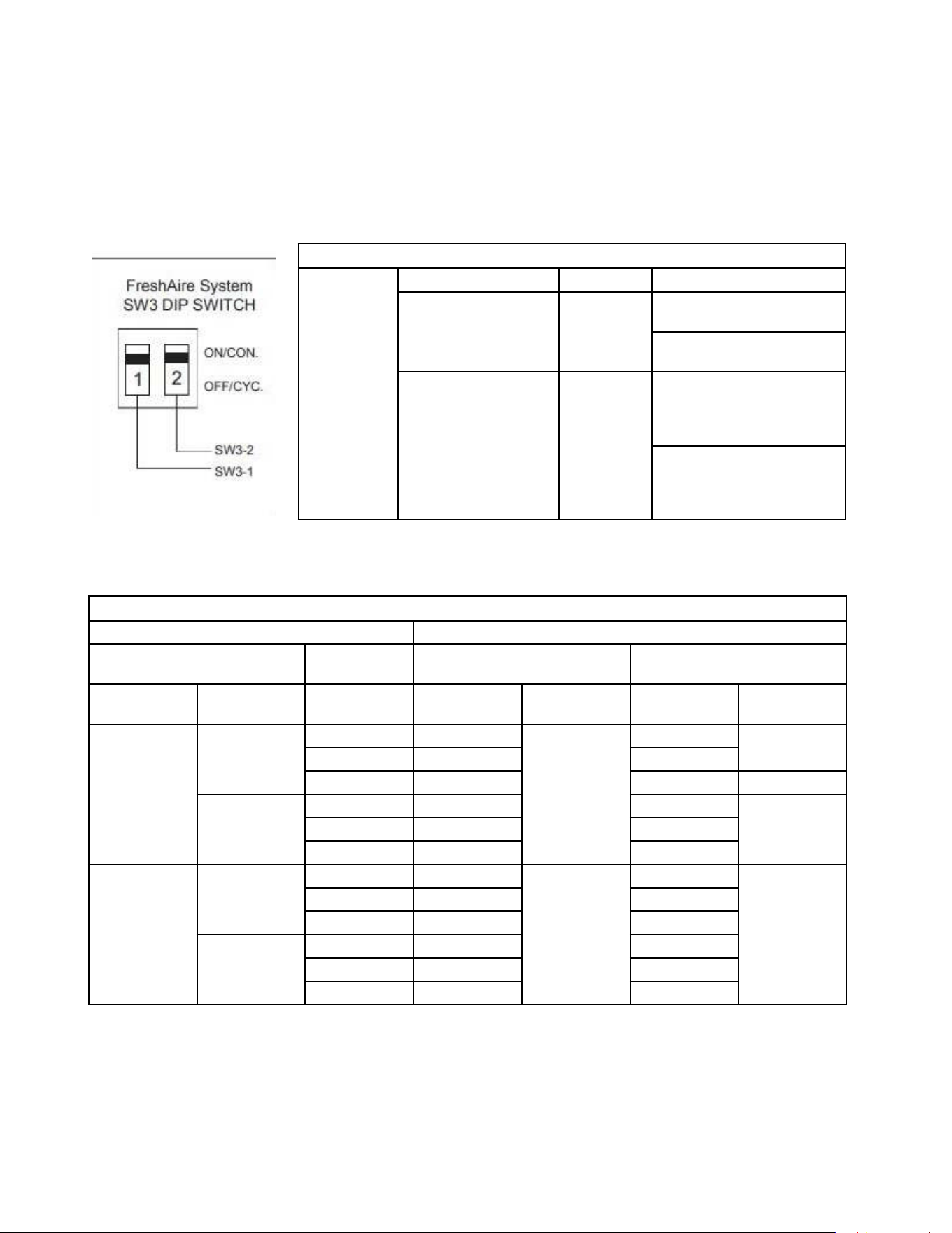
7) Smart fresh air system
The control logic as the below table 1 and table 2 , the DIP switch is SW3 on the main board.
DIP switch SW3 function
Freshaire
System
Engagement Method Mode Description
Sw3 Dip Switch 1 ON/ OFF FA fan runs only when Dip
Switch is set to "ON"
FA fan NEVER RUNS when Dip
Switch is set to "OFF"
Sw3 Dip Switch 2 Cycle/ Con-
tinuous
FA fan cycles On/ Off with
the unit indoor fan when Dip
Switch 1 is set to "ON" & Dip
Switch 2 is se to "Cycle"
"FA fan runs continuously
when Dip Switch 1 is set to
""ON"" & Dip Switch 2 is set to
""Continuous"""
Relationship Between Inputs and Outputs
INPUTS OUTPUT
FreshAir Mode 24V wall
Thermostat
In Demand No Demand
Enable Continuous ID Fan
Speed Selection
ID Fan
Operation
Fresh-Air Fan
Operation
ID Fan
Operation
Fresh-Air Fan
Operation
YES NO High High ON High ON
low low low
Auto Auto OFF OFF
YES High High High O N
low low low
Auto Auto low
NO NO High High OFF High OFF
low low low
Auto Auto OFF
YES High High High
low low low
Auto Auto OFF
21
OPERATION
Function and Control
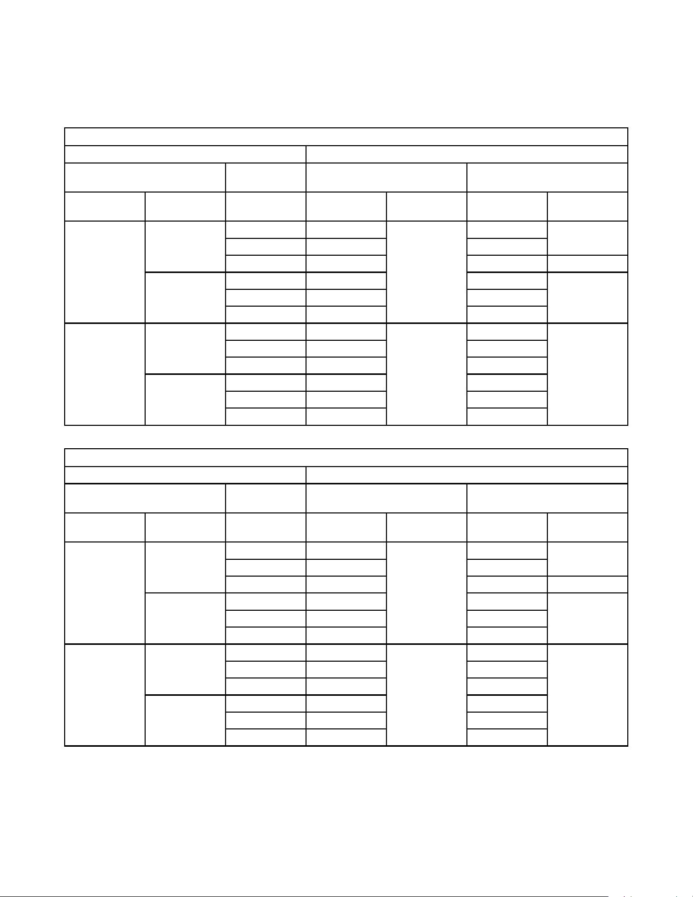
Relationship Between Inputs and Output by 24V Wall Thermostat
INPUTS OUTPUT
FreshAire Mode 24V wall
Thermostat
In Demand No Demand
Enable Continuous ID Fan
Speed Selection
ID Fan Operation Fresh-Air Fan
Operation
ID Fan Operation Fresh-Air Fan
Operation
YES NO High High ON High ON
low low low
Auto Auto OFF OFF
YES High High High O N
low low low
Auto Auto low
NO NO High High OFF High OFF
low low low
Auto Auto OFF
YES High High High
low low low
Auto Auto OFF
Relationship Between Inputs and Output by 12V Wall Thermostat
INPUTS OUTPUT
FreshAire Mode 12V wall
Thermostat
In Demand No Demand
Enable Continuous ID Fan
Speed Selection
ID Fan Operation Fresh-Air Fan
Operation
ID Fan Operation Fresh-Air Fan
Operation
YES NO High High ON High ON
low low low
Auto Low OFF OFF
YES High High High ON
low low low
Auto Low low
NO NO High High OFF High OFF
low low low
Auto Low OFF
YES High High High
low low low
Auto Low OFF
22
OPERATION
Function and Control
Advanced Functions
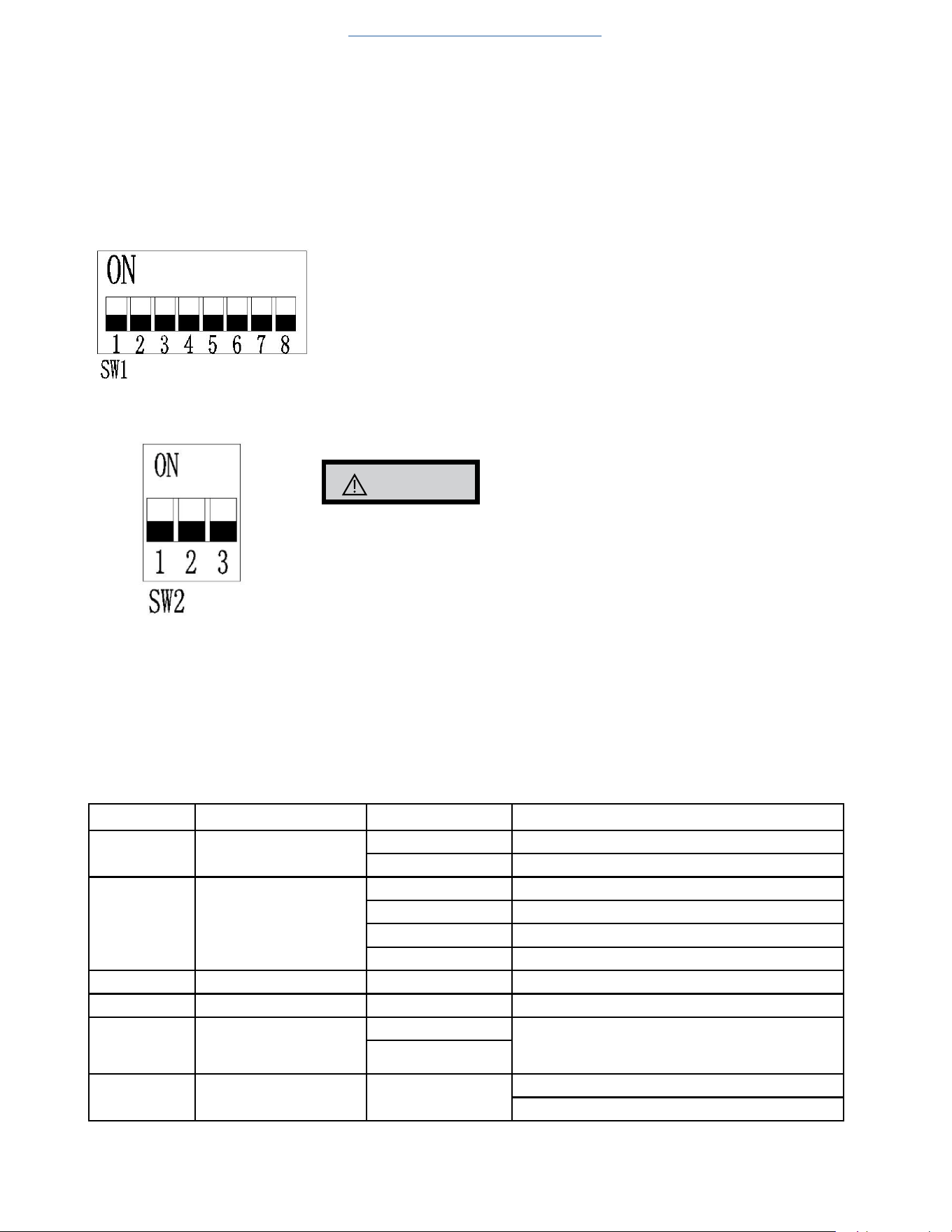
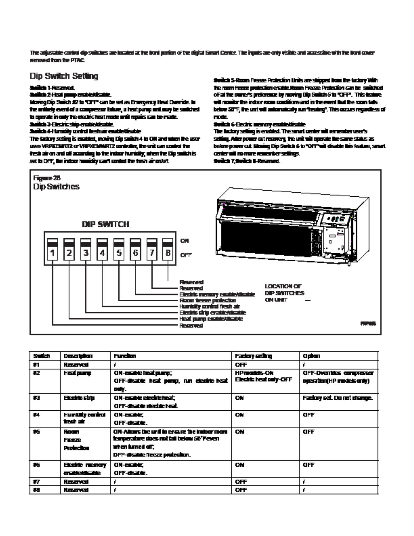
1) DIP Switch Function [after reprogramming, disconnect the power cord and wait 2 minutes for the electronic components (capacitors/
resistors) to cool down or bleed off. Then power up again to make changes effective]
1 Reserved
2 Heat pump
ON- valid; OFF-invalid
3 E-heater
ON- valid; OFF-invalid
4 Humidity Control & Fresh Air Activate ON
5 Room freeze protection
ON- valid; OFF- invalid
6 Auto-restart
ON- valid; OFF- invalid
7 Reserved
8 Reserved
CAUTION
SW2 DIP switch must be matched with the unit capacity, otherwise the compressor will fail
to operate correctly. Do not change dip switches on SW2!
Advanced Settings
Under OFF mode, hold [COOL] and [LOW] two keys at the same time continuously for 5 seconds. ‘d0’ will be displayed, indicating that the
system has entered the advanced operation status.
[COOL] key is used to switch parameter code and parameter value;
[+] or [-] keys are used to switch parameter code or set parameter value;
[ON/OFF] key is used to save and exit settings.
Menu NO. Function "Parameter value" Explanation
do Unit of temperature F Fahrenheit (default)
C Celsius
dl Control master p By control panel or IR remote thermostat(default)
r By 24V universal remote thermostat
rE By12V smart wired controller
rF VRPXEMRT2 and VRPXEMWRT2
d2 Max temperature setting d3 to 90°F The Min value is d2 (default 90°F)
d3 Min temperature setting 60°F to d2 The Max value is d3 (default 60°F)
d4 Indoor temperature cali-
bration
-9°C to 9°C If unit of temperature is changed, calibration should
be done again. If using the default value, it can be
ignored. (default 0°C/O°F)
-9°F to 9°F
d5 Temperature display
selection
O o r 1 0- displays room temperature (default ),
1- displays set point.
Return to Basic Troubleshooting
23
OPERATION
Function and Control
Advanced Settings Example
Setting target: d0(C), d1(r), d2(86°F), d3(64°F), d4(30°F), d5(1).
Step 1: hold [HEAT] and [FAN SPEED] two keys at the same time continuously for 5 seconds. Display:’d0’’
Step 2: short press [HEAT] key. Display: ‘F’
Step 3: short press [+] or [-] key. Display: ‘C’ (setting d0 has finished)
Step 4: short press [HEAT] key. Display:’d0’
Step 5: short press [+] key. Display:’d1’
Step 6: short press [HEAT] key. Display: ‘P’
Step 7: short press [+] or [-] key. Display: ‘r’ (setting d1 has finished)
Step 8: short press [HEAT] key. Display:’d1’
Step 9: short press [+] key. Display:’d2’
Step10: short press [HEAT] key. Display:’32’
Step11: short press [-] key twice. Display:’86’ (setting d2 has finished)
Step12: short press [HEAT] key. Display:’d2’
Step13: short press [+] key. Display:’d3’
Step14: short press [HEAT] key. Display:’16’
Step15: short press [+] key twice. Display:’64’ (setting d3 has finished)
Setp16: short press [HEAT] key. Display:’d3’
Step17: short press [+] key. Display:’d4’
Setp18: short press [HEAT] key. Display:’0’
Memory Function
The unit will run the same status from the last moment before power down.
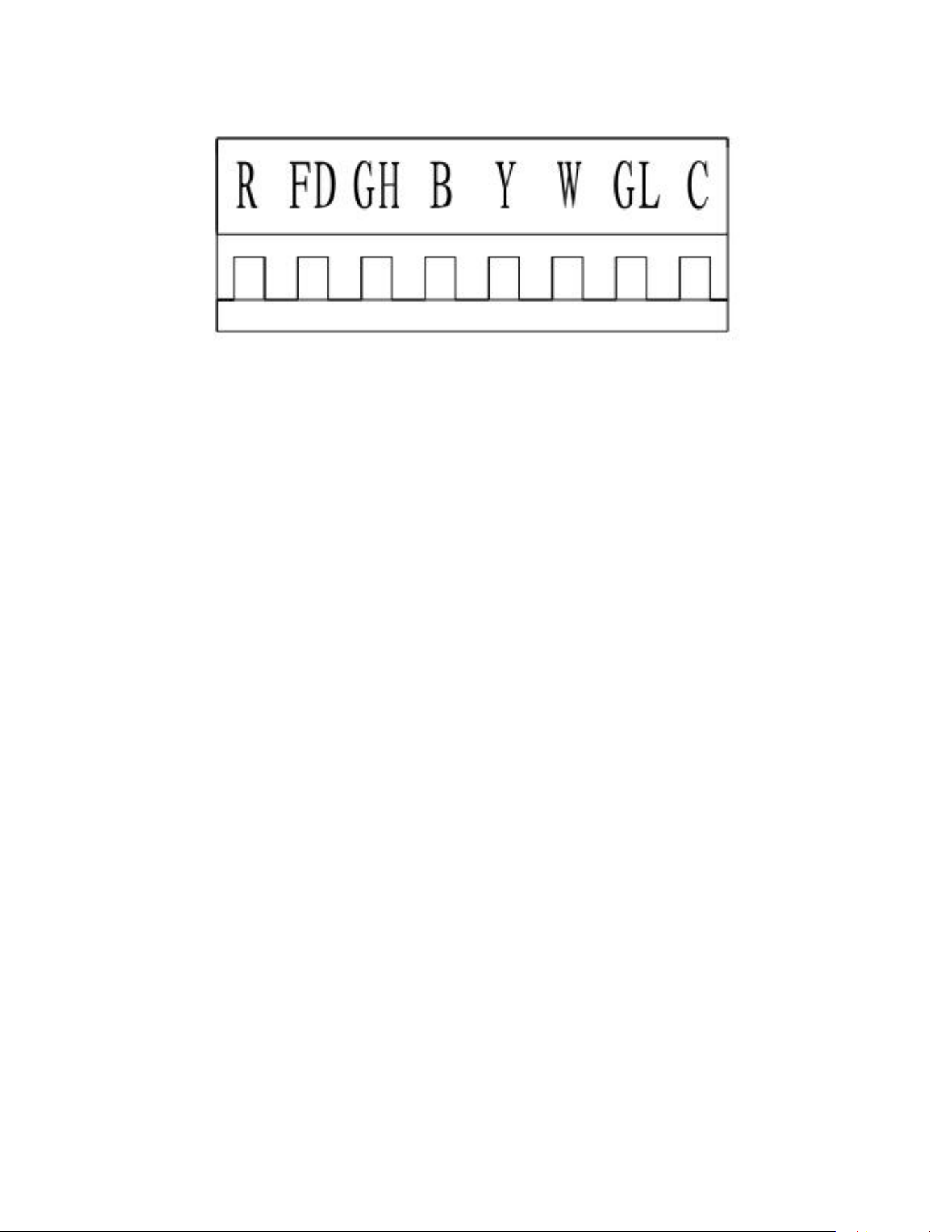
FD Control (front-desk control) & 24V REMOTE THERMOSTAT
The unit can be turned ON/OFF by front desk control switch. The control terminal is located on the remote thermostat interface, FD.
24
OPERATION
Function and Control
Control logic
(a). Turn ON unit: short R and FD then release one time within 5s.
(b). Turn OFF unit: short R and FD then release twice within 5s.
(c). Force unit shut down for one time: short R and FD short over 5s.
NOTE: After forcing unit shut down, you can turn on the unit again by control panel.
For the 24V remote thermostat compressor runs in different frequencies according to different temperature conditions and capacity
demands. You don’t need to change the wiring.
Protection Functions
To ensure the system running safely, electric control has following protections. For problem solving, please refer to TROUBLE SHOOTING sections.
1) Outdoor unit overload protection in COOLING mode
When condenser coil temperature exceeds the 140˚F, compressor decreases the operating frequency to 30Hz. If this protection is not
enough and condenser coil temperature reaches 149˚F, compressor will be turned off.
2) Evaporator Freeze protection (will not display error code)
When evaporator coil temperature drops to 1°C and lasts for 5 minutes, compressor and outdoor fan will stop,but indoor fan keeps
on running.
3) Compressor discharge overheat protection
When compressor discharge temperature reaches 226˚F, compressor will decrease operating frequency to 30Hz. If this protection is
not enough and discharge temperature reaches 239˚F, compressor will be turned off.
4) Evaporator overheat protection in HEAT PUMP mode
When evaporator coil temperature exceeds 140˚F, compressor decreases the operating frequency to 30Hz. If this protection is not
enough and evaporator coil temperature reaches 149˚F, compressor will be turned off. At this time the back-up electric heater will
be turned on.
5) Input over-current protection
When input current exceeds 8 amps, compressor will decrease the operating frequency to 30Hz. If this protection is not enough and
current reaches 9 amps, compressor will be turned off.
6) Compressor over-current protection.
When compressor operating current exceeds 7.5 amps, the compressor will be shut down.
7) IPM fault protection
When IPM faults, include overheat or over current, unit will be shut down and all outputs are shut down. Control panel displays the error
code.
8) Temperature sensor fault protection
Any temperature sensor faults will shut down unit. The error code will be displayed
.

25
OPERATION
Function and Control
9) Communication fault protection
If communication faults between indoor unit and outdoor unit for continuously 2 minutes, unit will shut down and display error code on
display panel.
10) Compressor starting fault
If compressor fails to start, it will try to restart after 3 minutes. Error code will not be displayed on display panel for the first 3 attempts to
restart. If the compressor fails to start on the 4th try, it will not attempt restart any more and an error code will occur.
11) DC-BUS overvoltage/undervoltage protection
If the unit senses the DC-BUS is overvoltage or undervoltage, the unit stops and an error code will occur. and be displayed on display panel.
12) EEPROM fault
When the unit is powered up, if system monitors the EEPROM chip fault (broken chip or incorrect data),
control panel displays error code and will not operate any more.
26
OPERATION
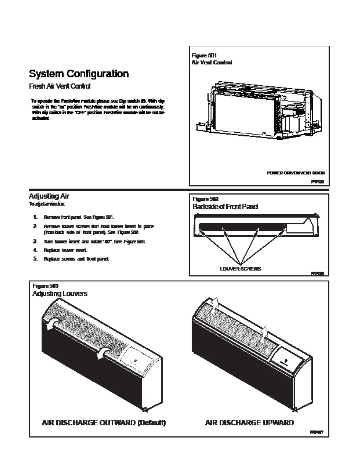
System Configuration Fresh Air Vent Control
27
OPERATION
System Configuration Fresh Air Vent Control
28
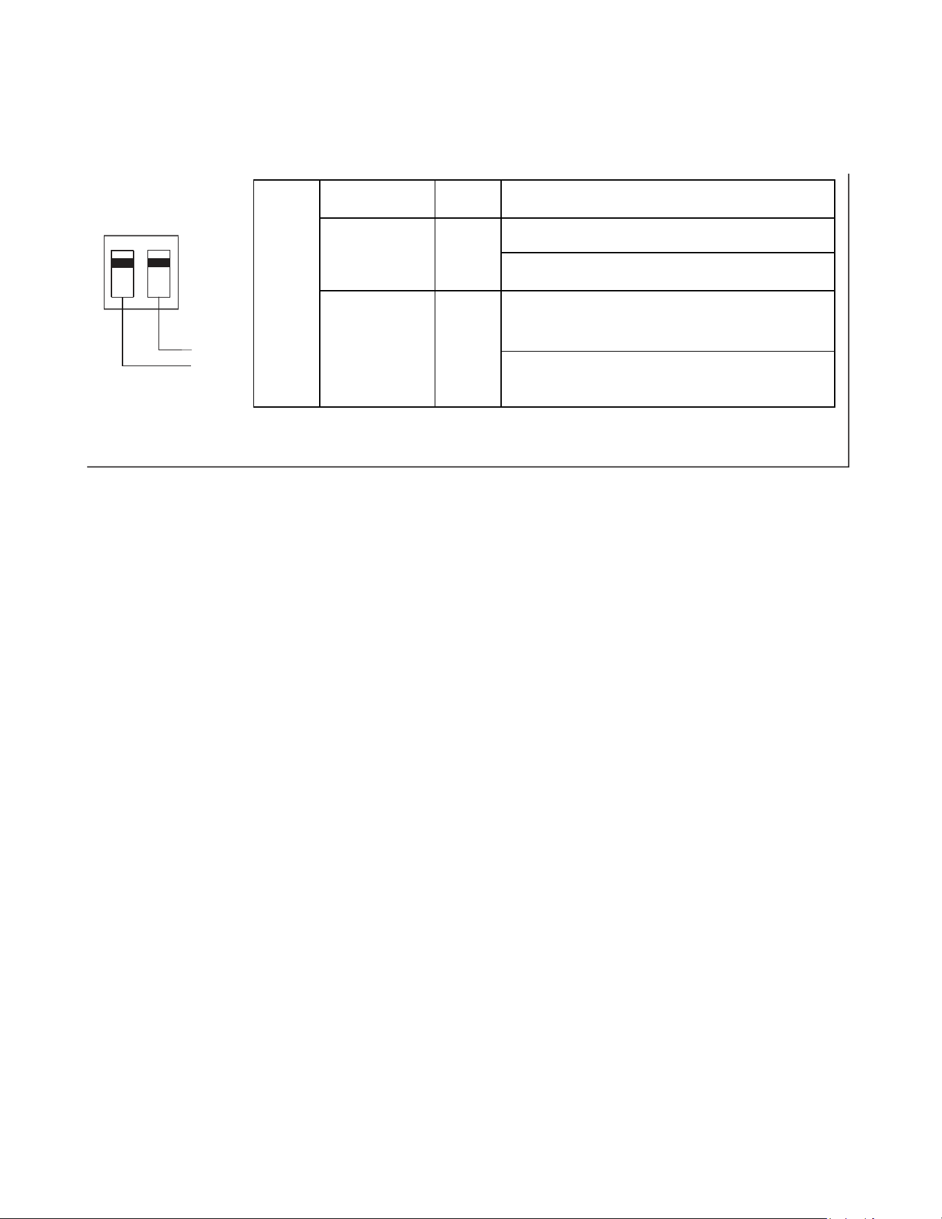
23
FreshAire
System
Engagement
Method
Mode Description
SW3-1 ON / OFF
Fresh-Air Fan runs only when Dip Switch is set to ‘ON’
Fresh-Air Fan NEVER RUNS when Dip Switch is set to
‘OFF’
SW3-2
Cycle /
Continuous
Fresh-Air Fan cycles On/Off with the Unit Indoor Fan
when SW3-1 is set to 'ON' & SW3-2 is set to 'OFF'
Fresh-Air Fan runs continuously when SW3-1 is set to
'ON' & SW3-2 is set to 'ON'
2
FreshAire System
SW3 DIP SWITCH
ON/CON.
1
OFF/CYC.
SW3-2
SW3-1
OPERATION
System Configuration Fresh Air Vent Control
29
24
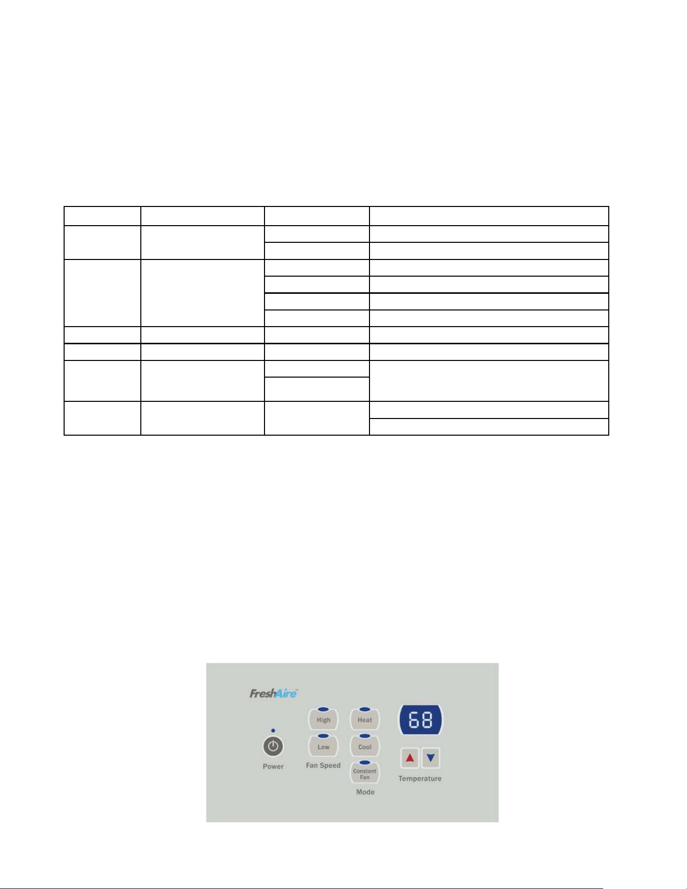
Digital Control Operation
Figure 29
Digital Control Panel
Cooling Mode
Emergency Heat Operation
FRP029
Pressing the “Cool” button after turn the unit on will put the unit into
cooling mode. Press “UP” or “DOWN” button to adjust the set point, the
unit will start the compressor and run appropriate frequency to maintain a
comfortable room temperature. The compressor will come on anytime that
the room temperature is 2℉above the set point. The fan will come on with
compressor.
Heating Mode
After turn on the unit, press the “Heat” button will put the unit into heating
mode.
Heat Pump Models (PVH)
When the “Heat” button is pressed initially the unit may call for electric
strips to bring the room to the set point. When the room temperature falls
2℉below the set point, the unit will turn on the compressor or electric
strip. The fan will run with compressor or electric strips. When the outdoor
ambient temperature falls below 32°F or outdoor coil temperature drops to
5℉, the unit will operate the electric strip instead of heat pump. During
heat pump mode, CPU detects the outdoor coil gets freeze, unit will go to
defrost. During the defrost operation (10min at most), there will be no
heating provide. After finishing defrost, electric heating will come on to
warm the room quickly.
In the event of a compressor failure in heat pump mode, the compressor
may be locked out to provide heat through the electric strip heater
automatically. This feature ensures that even in the unlikely event of a
compressor failure, the room temperature can be maintained until the
compressor can be serviced. If the unit still can’t run electric heater stably,
switch Dip switch 2 to OFF, it controls the emergency heat setting.
Constant Fan
Pressing the “Constant Fan” button will provide constant or cycle fan
operation in cooling or heating modes. The fan speed selection is
made by pressing either “High” or “Low” fan speed button.
OPERATION
Digital Control User Input Configuration
30
OPERATION
Settings- Detailed Configurations
This section is about how to set the unit operating parameter, include display temperature unit, Fahrenheit or Celsius, control master, temperature limit, temperature
calibration, display set point or room temperature.
Under OFF mode, hold [Cool] and [Low] two keys at the same time continuously for 5 seconds. This time displays ‘d0’, indicates that system has entered the senior
operation status.
[Cool] key is used to switch parameter code and parameter value;
[UP] or [DOWN] keys are used to switch parameter code or set parameter value; [Power] key is used to save
and exit settings.
Menu NO. Function "Parameter value" Explanation
do Unit of temperature F Fahrenheit (default)
C Celsius
dl Control master p By control panel
r By 24V universal remote thermostat
rE By 12V smart wired controller
rF VRPXEMRT2 and VRPXEMWRT2
d2 Max temperature setting d3 to 90°F The Min value is d2 (default 90°F)
d3 Min temperature setting 60°F to d2 The Max value is d3 (default 90°F)
d4 Indoor temperature calibra-
tion
-9°C to 9°C If unit of temperature is changed, calibration should be done
again. If using the default value, it can be ignored. (default
0°C/O°F)
-9°F to 9°F
d5 Temperature display selec-
tion
O o r 1 0- displays room temperature (default ),
1- displays set point.
One example:
Setting target:d0(C),d1(r), d2(88),d3(58),d4(-1),d5(1).
Step1: hold [Cool] and [Low] two keys at the same time continuously for 5 seconds. Display:’d0’
Step2: short press [Cool] key. Display: ‘F’(setting d0 has finished)
Step3: short press [Cool] key. Display:’d0’
Step4: short press [UP] key. Display:’d1’
Step5: short press [Cool] key. Display: ‘P’
Step6: short press [UP] or [DOWN] key. Display: ‘r’ (setting d1 has finished)
Step7: short press [Cool] key. Display:’d1’
Step8: short press [UP] key. Display:’d2’
Step9: short press [Cool] key. Display:’90’
Step10: short press [DOWN] key twice. Display:’88’ (setting d2 has finished)
Step11: short press [Cool] key. Display:’d2’
Step12: short press [UP] key. Display:’d3’
Step13: short press [Cool] key. Display:’60’
Step14: short press [UP] key twice. Display:’58’ (setting d3 has finished)
Step15: short press [Cool] key. Display:’d3’
Step16: short press [UP] key. Display:’d4’
Step17: short press [Cool] key. Display:’0’ (setting d4 has finished)
Step18: short press [Power] key to exit.

31
OPERATION
General Knowledge Sequence Of Refrigeration
A good understanding of the basic operation of the refrigeration system is essential for the service technician. Without this understanding, accurate
troubleshooting of refrigeration system problems will be more difficult and time consuming, if not (in some cases) entirely impossible. The refrigeration
system uses four basic principles in its operation which are as follows:
1. “Heat always flows from a warmer body to a cooler body.”
2. “Heat must be added to or removed from a substance before a change in state can occur”
3. “Flow is always from a higher pressure area to a lower pressure area.”
4. “The temperature at which a liquid or gas changes state is dependent upon the pressure.”
The refrigeration cycle begins at the compressor when a demand is received from the thermostat. Starting the compressor creates a low pressure
in the suction line which draws refrigerant gas (vapor) into the compressor. The compressor then “compresses” this refrigerant vapor, raising its
pressure and its (heat intensity) temperature.
The refrigerant leaves the compressor through the discharge line as a hot high pressure gas (vapor). The refrigerant enters the condenser coil where
it gives up some of its heat. The condenser fan moving air across the coil’s finned surface facilitates the transfer of heat from the refrigerant to the
relatively cooler outdoor air.
When a sufficient quantity of heat has been removed from the refrigerant gas (vapor), the refrigerant will “condense” (i.e. change to a liquid). Once the
refrigerant has been condensed (changed) to a liquid it is cooled even further by the air that continues to flow across the condenser coil.
The design determines at exactly what point (in the condenser) the change of state (i.e. gas to a liquid) takes place. In all cases, however, the
refrigerant must be totally condensed (changed) to a liquid before leaving the condenser coil.
The refrigerant leaves the condenser coil through the liquid line as a warm high pressure liquid. I
The liquid refrigerant next enters the metering device. The metering device is called a capillary tube. The purpose of the metering device is to “meter”
(i.e. control or measure) the quantity of refrigerant entering the evaporator coil.
In the case of the capillary tube this is accomplished (by design) through size (and length) of device, and the pressure difference present across the
device. Since the evaporator coil is under a lower pressure (due to the suction created by the compressor) than the liquid line, the liquid refrigerant
leaves the metering device entering the evaporator coil. As it enters the evaporator coil, the larger area and lower pressure allows the refrigerant
to expand and lower its temperature (heat intensity). This expansion is often referred to as “boiling” or atomizing. Since the unit’s blower is moving
indoor air across the finned surface of the evaporator coil, the expanding refrigerant absorbs some of that heat. This results in a lowering of the indoor
air temperature, or cooling.
The expansion and absorbing of heat cause the liquid refrigerant to evaporate (i.e. change to a gas). Once the refrigerant has been evaporated
(changed to a gas), it is heated even further by the air that continues to flow across the evaporator coil.
The particular system design determines at exactly what point (in the evaporator) the change of state (i.e. liquid to a gas) takes place. In all cases,
however, the refrigerant must be totally evaporated (changed) to a gas before leaving the evaporator coil.
The low pressure (suction) created by the compressor causes the refrigerant to leave the evaporator through the suction line as a cool low pressure
vapor. The refrigerant then returns to the compressor, where the cycle is repeated.
32
OPERATION
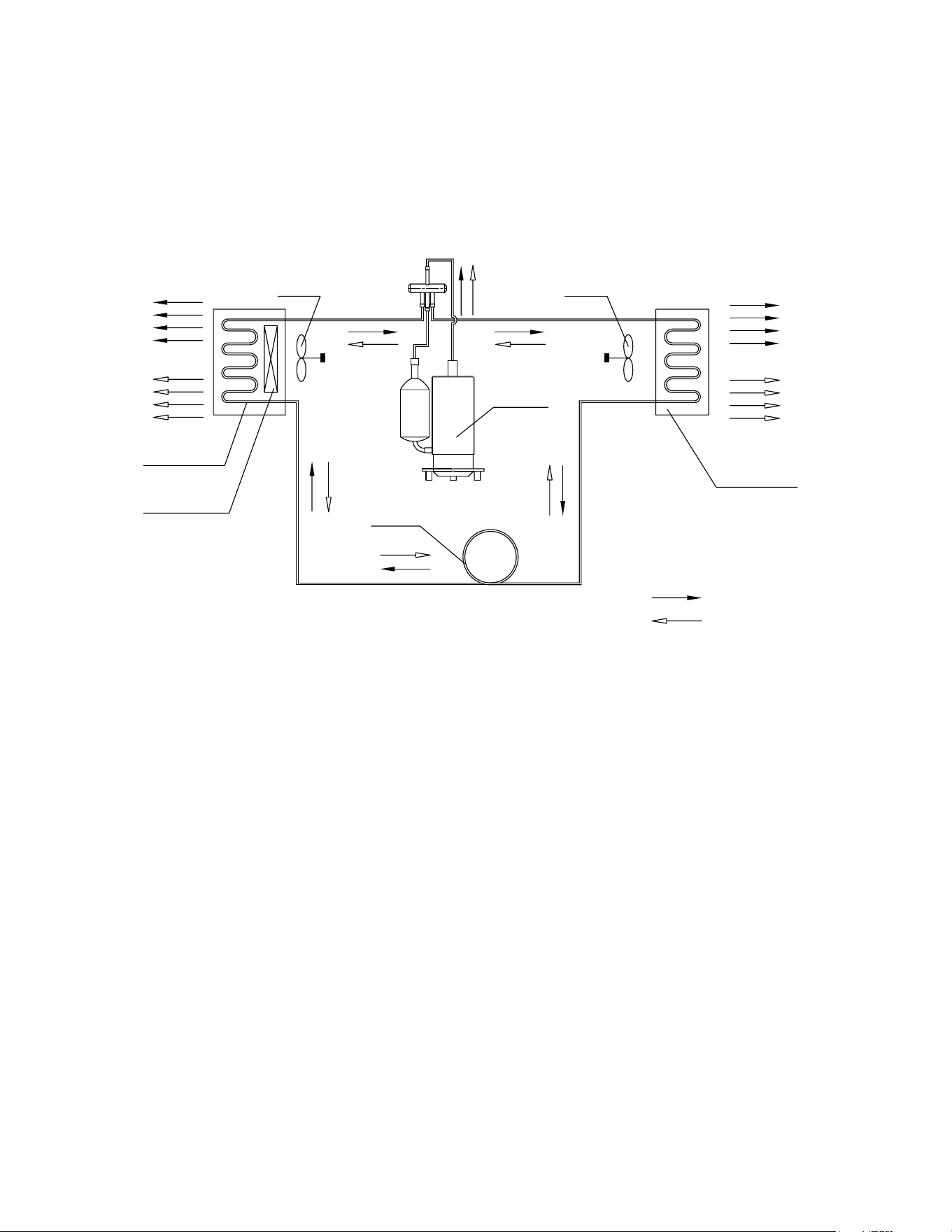
Refrigerant System Diagram
COOLED AIR
OUTDOOR COILS
HOT DISCHARGED AIR
CAPILLARY
AXIAL FAN
COMPRESSOR
HEATING MODE
COOLING MODE
NOTES:
REFRIGERANT FLOW DIRECTION
CENTRIFUGAL
OR CROSS FAN
HOT AIR
INDOOR COILS
ELECTRIC HEATER
COOLED AIR
Figure 301 (Sequence of Operation)

33
Coils & Chassis
NOTE: Do not use a caustic (alkaline) or acidic cleaning agent on coils or base pan. Use a biodegradable cleaning agent and de-greaser. The use of
harsh cleaning materials may lead to deterioration of the aluminum fins or the coil end plates.
The indoor coil and outdoor coils and base pan should be inspected periodically (annually or semi-annually) and cleaned of all debris (lint, dirt, leaves,
paper, etc.) as necessary. Under extreme conditions, more frequent cleaning may be required. Clean the coils with and base pan with a coil comb or soft
brush and compressed air or vacuum. A low pressure washer device may also be used; however, you must be careful not to bend the aluminum fin pack.
Use a sweeping up and down motion in the direction of the vertical aluminum fin pack when pressure cleaning coils.
NOTE: It is extremely important to insure that none of the electrical and/ or electronic parts of the unit get wet when cleaning. Be sure to cover all
electrical components to protect them from water or spray.
NOTE: When installed on or near sea coast environments, it recommended that all coils be cleaned at minimum biannually.
Decorative Front
Use a damp (not wet) cloth when cleaning the control area to prevent water from entering the unit, and possibly damaging the electronic control.
The decorative front and the cabinet can be cleaned with warm water and a mild liquid detergent. Do NOT use solvents or hydrocarbon based cleaners
such as acetone, naphtha, gasoline, benzene, etc.
The indoor coil can be vacuumed with a dusting attachment if it appears to be dirty. DO NOT BEND FINS. The outdoor coil can be gently sprayed with a
garden hose.
The air filter should be inspected weekly and cleaned if needed by vacuuming with a dust attachment or by cleaning in the sink using warm water and a
mild dishwashing detergent. Dry the filter thoroughly before reinstalling. Use caution, the coil surface can be sharp.
Fan Motor & Compressor
The fan motor & compressor are permanently lubricated and require no additional lubrication.
Wall Sleeve
Inspect the inside of the wall sleeve and drain system periodically (annually or semi-annually) and clean as required. Under extreme conditions, more
frequent cleaning may be necessary. Clean both of these areas with an antibacterial and antifungal cleaner. Rinse both items thoroughly with water and
ensure that the drain outlets are operating correctly. Check the sealant around the sleeve and reseal areas as needed.
Inspect for mold or mildew periodically. If present, ensure the sealing gasket around the unit is in good condition and not allowing outside air (or light)
through the gasket.
Blower Wheel / Housing / Condensor Fan / Shroud
Inspect the indoor blower and its housing, evaporator blade, condenser fan blade and condenser shroud periodically (yearly or bi-yearly) and clean of
all debris (lint, dirt, mold, fungus, etc.). Clean the blower housing area and blower wheel with an antibacterial / antifungal cleaner. Use a biodegradable
cleaning agent and degreaser on condenser fan and condenser shroud. Use warm or cold water when rinsing these items. Allow all items to dry
thoroughly before reinstalling them.
Electrical / Electronic
Periodically (at least yearly or bi-yearly) inspect all control components: electronic, electrical and mechanical, as well as the power supply. Use proper
testing instruments (voltmeter, ohmmeter, ammeter, wattmeter, etc.) to perform electrical tests. Use an air conditioning or refrigeration thermometer to
check room, outdoor and coil operating temperatures.
Air Filter
To ensure proper unit operation, the air filter should be cleaned at least monthly, and more frequently if conditions warrant. The unit must be turned off
before the filter is cleaned.
ROUTINE MAINTENANCE
34
INSTALLATION
PTAC Installation Recommendations
5
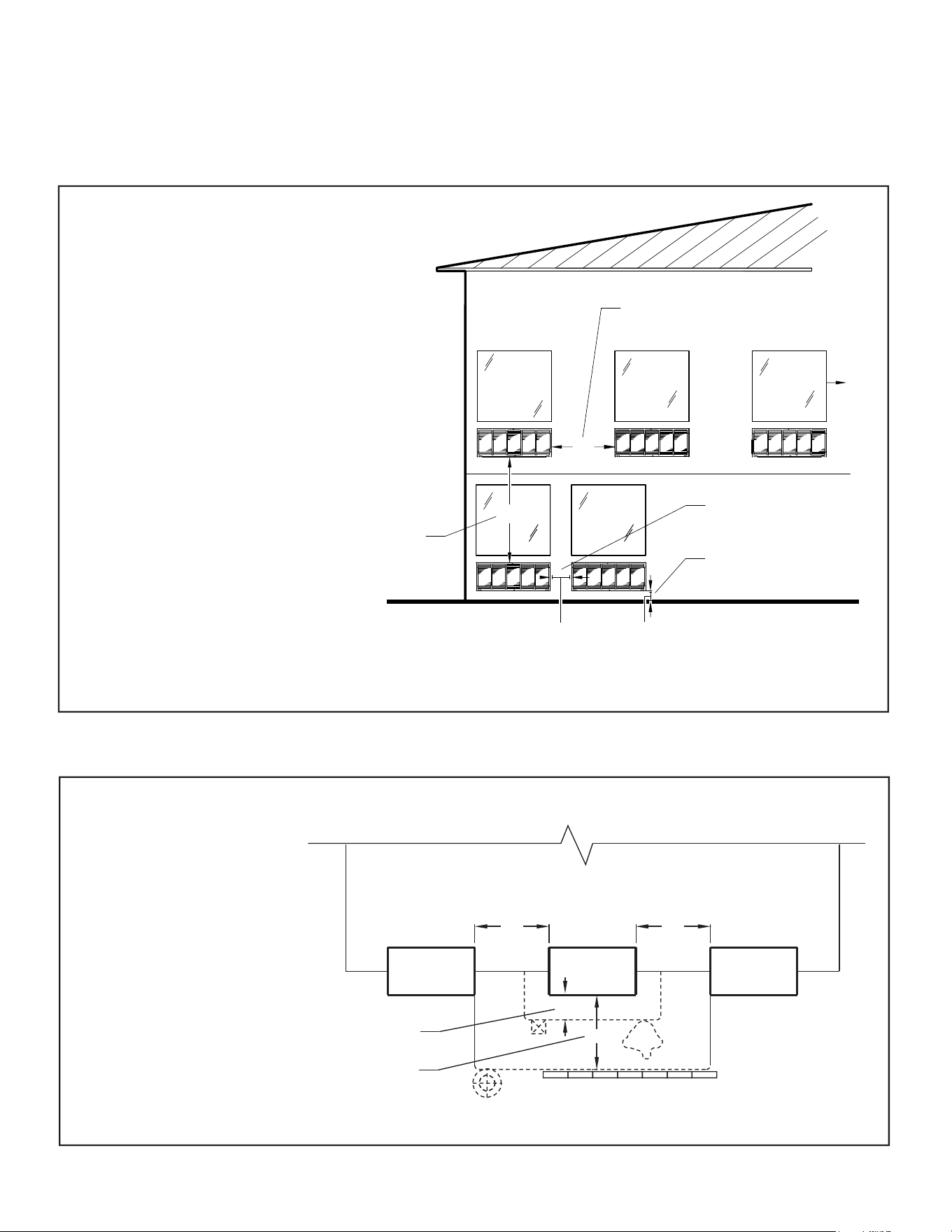
PTAC Installation Recommendations
For proper PTAC unit performance and maximum operating life refer to the minimum installation clearances
below:
Figure 1
PTAC units should be installed no
closer than 12" apart when two
units are side by side. If three or
more PTAC units are to operate
next to one another allow a
minimum of 36" between units.
Also,a vertical clearance of 60"
should be maintained between
units installed. In the interior of
the room the unit should be
located a minimum of 1/4" from the
floor and a minimum of 36"
from the ceiling.
FRP001
For PTACs on the ground floor or anytime obstructions are present, use the following guidelines:
Figure 2
• For minor obstructions
such as lamp poles or small
shrubbery a clearance of
12" from the outdoor louver
should be maintained.
TYPICAL BUILDING ( PLAN VIEW )
• For major obstructions such
as a solid fence, wall or
other heat rejecting device
like a condensing unit, a
minimum distance of 36"
should be kept.
PTAC
12" MINIMUM, MINOR
OBSTRUCTIONS
36" MIMUMUM, MAJOR
36"
POLE
PTAC
12"
36"
36"
SHRUB
PTAC
OBSTRUCTIONS
CONDENSING UNIT
FENCE OR WALL
FRP002
The above suggestions are for reference only and do not represent all possible installations.Please contact Friedrich for information regarding affects of other
installation arrangements.By following these simple recommendations you can be confident that your Friedrich PTAC will provide years of worry free operation.
THREE OR MORE PTACs
ADJACENT 36" MINIMUM
GROUND FLOOR PTACs
6" MINIMUM FROM GRADE
TWO ADJACENT PTACs
12" MINIMUM
TYPICAL
WINDOW
12"
6"
VIEW: OUTSIDE BUILDING ELEVATION
60" VERTICAL
MINIMUM
BETWEEN
PTACs
36"
60"
35
INSTALLATION
Wall Sleeve Installation Instructions (PDXWS)
6
Wall Sleeve Installation Instructions (PDXWSA)
NOTE: Insure that the unit is only installed in a wall structurally adequate to support the unit including the sleeve, chassis and accessories.If the sleeve
projects more than 8" into the room, a subbase or other means of support MUST be used. Please read these instructions completely
before attempting installation.
WARNING
Falling Object Hazard
Not following Installation Instructions for
mounting your air conditioner can result
in property damage, injury, or death.
NOTICE
DO NOT allow any pitch toward the inside.
Flashing on all 4 sides of the opening is recommended.
Potential property damage can occur if instructions are
not followed.
For Deep Wall Installation (Greater than 13
1/4")
See next page
The following instructions apply ONLY to walls less than 13 ¼" in depth.
1 The PXDR10 Drain Kit,(optional for new construction) see page 10
if applicable, must be installed before the wall sleeve is installed
into the wall.
2 The External Drain (for new construction or unit replacement) see
other page if applicable, must be installed before the wall sleeve
is installed into the wall.
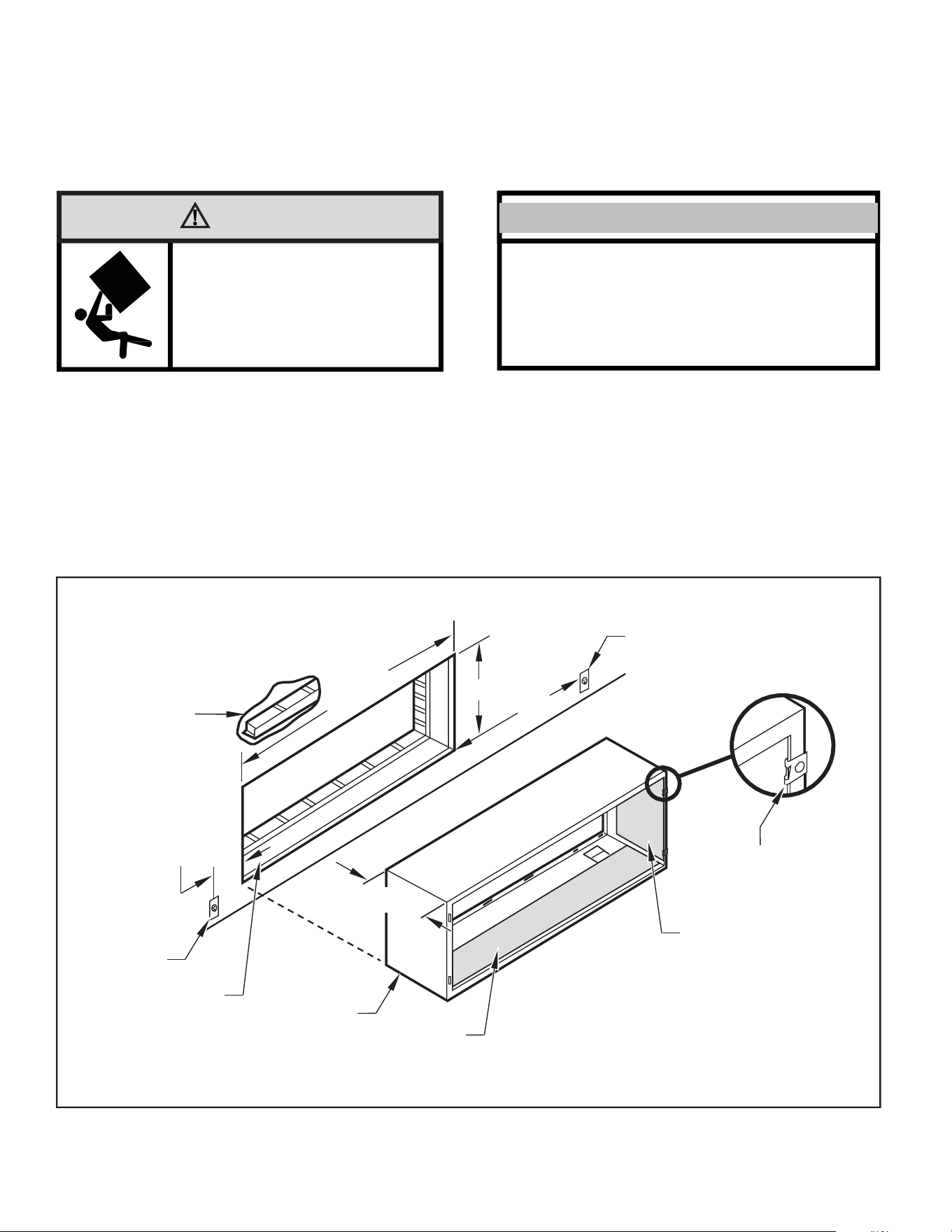
Figure 3
Typical Wall Sleeve Installation
3
From inside the building, position the wall sleeve in the opening and
push it into the wall until it protrudes at least ¼” on the outside
(See Figure 9,).
4 Position the wall sleeve with a slight tilt towards the outside to
facilitate condensate drainage. It should be level side-to-side and
the front should be ¼ bubble higher than the back.
ELECTRICAL
RECEPTACLE
LINTEL TO SUPPORT
MASONRY WALLS
42-¼"
MIN.
16-¼
"
60
"
MAX.
20
"
MAX.
13-¾
"
SMOOTH SIDE OF SCREW
CLIP FACING INTO ROOM
ELECTRICAL
RECEPTACLE
INSULATION
WALL OPENING
WALL SLEEVE
INSULATION
NOTE:
All 230/208V units are manufactured with a 60” power cord and all 265V units with a 18” power cord.
FRP003
36
INSTALLATION
Alternate Wall Installations
7
Figure 4
Panel Wall
Figure 6
Curtain Wall
WALL OR
WINDOW
1/4" MIN
PROJECTIO
N
CASE FLANGE
(BY OTHERS)
OPTIONAL SUBBASE
LEVELING SCREW
OPTIONAL SUBBASE
FRP004
LEVELING SCREW
FRP006
Figure 5
Frame and Brick Veneer
Figure 7
Block and Brick Veneer
1/4" MIN
PROJECTION
1/4" MIN
PROJECTION
WOOD FRAME
CONCRETE LINTEL
STEEL
LINTEL
13-3/4" MIN.
STEEL
LINTEL
11" MIN.
WITH SUBBASE
WITHOUT SUBBASE
OPTIONAL SUBBASE
LEVELING SCREW
FRP005
RECEPTACLE
FINISHED FLOOR
POWER SUPPLY CONDUIT
(SUPPLIED BY INSTALLER)
FRP007
NOTE: Follow all wall system manufacturer installation instructions. For sunrooms and modular buildings, adhere to their installation instructions for
supporting and sealing sleeve to their frames. All wall and window/wall installations must provide for proper drainage. In applications where the
drain holes on the PTAC wall sleeve are not exposed beyond the wall an internal drain system is recommended. It is the installer's responsibility
to ensure there is adequate drainage for the PTAC unit.
37
INSTALLATION
Alternate Wall Installations
8
13-¾
"
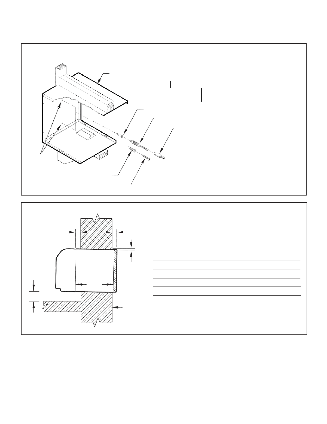
Figure 8
Wall Sleeve Attachment
WALL
SLEEVE
ALTERNATE
FASTENING METHODS
(Field Supplied)
WOOD SCREW
TOGGLE BOLT
NOTE: The Wall Sleeve must be
horizontally level (side-to-side)
and pitched 1/4 bubble to the
outside when installed in an
opening.
The mounting hole location
EXPANSION
ANCHOR BOLT
should be approximately 2-4”
from the top and bottom of the
sleeve.
MOUNTING
HOLES
PLASTIC ANCHORS
SCREWS
FRP008
Figure 9
Dimensions
A ¼" MIN.
A B C
Dimension* Allow
for wall
finishing
Allow
for floor
finishing
Allow
for proper
drainage
(Minimum) Min. Max.
(Front-to-Back)
C
No Accessories
¼" ¼"
---
---
With Subbase 1-¾" 3-½" 5"
---
With Lateral Duct ¾"
¼"
---
---
Wall Sleeve Tilt
B
--- --- ---
¼"
WALL
* If more than one accessory is to be used, use the maximum
dimension. If the wall thickness is more than 13-¾" - (A+ ¼"),
a sleeve extension must be used.
FRP009
38
INSTALLATION
Alternate Wall Installations
9
5. Drill two 3/16" holes through each side of the sleeve approximately
4" from top and 4" from bottom of sleeve. Screw four #10 x 1"
screws (included) or appropriate fasteners for your installation,
through the holes in the sides of the wall sleeve.
6. Apply sealant around the wall sleeve where it projects through the
inside and outside wall surfaces. Apply the sealant to the screw
heads or the tops of the fasteners used in Step #5.
7. If the chassis and exterior grille are to be installed later, leave the
weatherboard and center support in place, otherwise remove and
dispose of them. (See Figure 13, Page 12).
8. Provide a support lintel if the wall sleeve is installed in a concrete
or masonry wall (See Figure 10, Page 9).
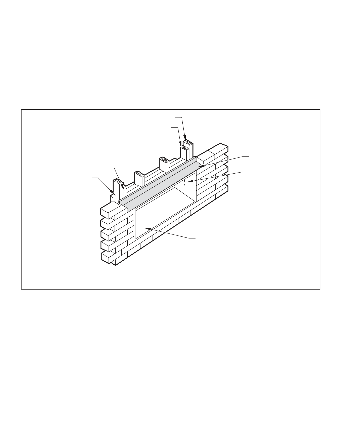
Figure 10
Lintel Installation
MAIN STUDS
JACK STUDS
JACK STUDS
MAIN STUDS
LINTEL
MOUNTING
SCREW HOLES
NO HOLES IN BOTTOM OF WALL
SLEEVE UNLESS DRAIN KIT IS USED
NOTE: Construct wall opening to comply with all applicable building codes.
FRP010
One-Piece Deep Wall Sleeve
Installation (PDXWSEXT)
If the wall is thicker than 13 1/4” a deep wall sleeve or wall sleeve extension
MUST be used. The deep wall sleeve may be special ordered through
your Sales Representative.
39
INSTALLATION
PXDR10 Drain Kit Installation
10
PXDR10 Drain Kit Installation
Instructions (optional for new
construction)
NOTE: Determine whether drain will be located within the wall, on the
indoor side, or will drain to the exterior of the building. Follow
appropriate instructions below depending on your particular
type of installation.
Internal Drain
NOTE: If installing an internal drain, you MUST install a drain kit on
the wall sleeve before the wall sleeve is installed.
1. Refer to Figure 11 and locate the drain within the “Preferred”
area of best drainage.Maintain at least a ½” clearance from the
embossed area.
2. Using the mounting plate with the ½” hole as a template, mark
and drill two, 3/16” mounting holes and a ½” drain hole in the
sleeve bottom.
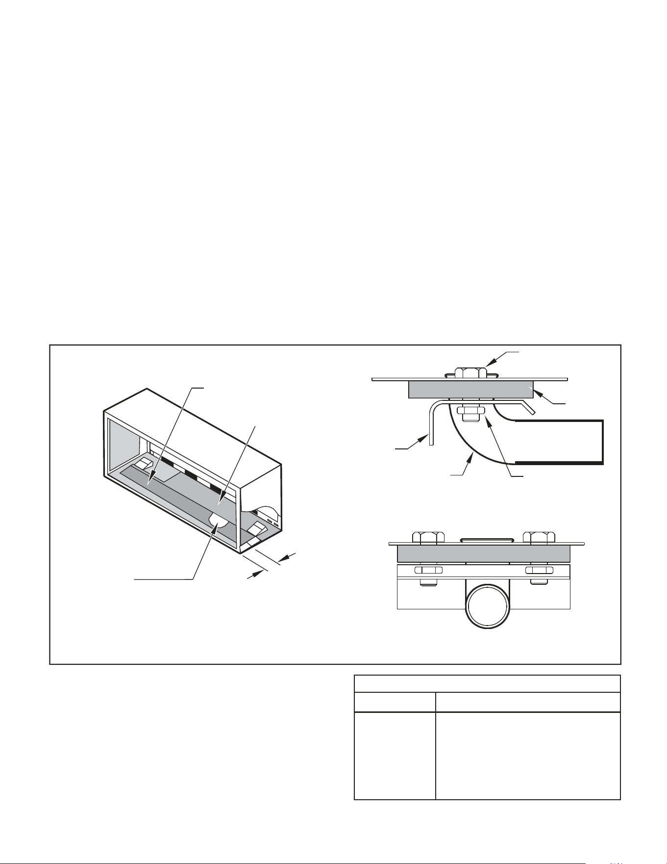
Figure 11
Drain Kit Location and Installation
OPTIONAL AREA
PREFERRED AREA-
NO FOAM INSULATION
3. Remove the backing from the gasket and mount it on the flat
side of the mounting plate (See Figure 12, Page 11). Insert the
drain tube through the hole in the gasket and mounting plate so the
tube flange will be against the wall sleeve.
4. Position the assembly beneath the drilled holes and secure it with
#10-24 x ½" machine screws and lock nuts provided. Seal the tops
of the screws with silicone caulking.
5. Use ½" I D copper tube, PVC pipe, or vinyl hose (obtained locally)
to connect the internal drain tube to the drain system in the building.
6. Referring to Figure 12, Detail A, Page 11, locate and assemble
the two cover plates and gaskets over the drain holes at the
rear of the wall sleeve. Attach them with the #10 sheet metal
screws provided. Make certain that the four overflow slots at
the rear of the wall sleeve are not blocked (See drawing of the
back of the sleeve Figure 12, Page 11).
7. If a deep wall extension (PDXWSEXT) is used, after installing the
field supplied flashing,caulk as required. Be sure to caulk around
the flashing and the wall sleeve where the hole was drilled for the
drain tube.
SCREW
WALL SLEEVE
GASKET
MOUNTING
PLATE
DRAIN TUBE
NUT
SIDE VIEW
IF THE DRAIN MUST BE
LOCATED IN THE OPTIONAL
AREA, THE FOAM INSULATION
MUST BE CUT AWAY AND
REMOVED TO ALLOW ACCESS
3"
TO THE DRAIN.
FRONT VIEW
FRP011
PXDR10
QUANTITY DESCRIPTION
2
COVER PLATES
1
MOUNTING PLATE
1
DRAIN TUBE
3
MOUNTING PLATE GASKET
4
#10 X ½” SHEET METAL SCREWS
2
#10-24 X ½ ” MACH. SCREWS
2
#10-24 X ½" LOCKNUTS
40
INSTALLATION
External Drain
11
External Drain (for new
construction or unit
replacement)
When using an external drain system, the condensate is removed through
either of two drain holes on the back of the wall sleeve. Select the drain
hole which best meets your drainage situation and install the drain kit.
Seal off the other with a cover plate.
Drain Tube Installation (See Figure 12)
1. Peel the backing tape off the gaskets and apply the sticky side
to one cover plate and one mounting plate as shown in Details
A and B.
2. Place the drain tube through the gasket and the mounting plate
with the flange toward the wall sleeve.
3. Attach the drain tube assembly to one of the two drain holes at the
rear of the wall sleeve. The large flange on the mounting plate is
positioned at the bottom of the sleeve facing toward the sleeve,
Detail B. When the drain tube is positioned at the desired angle,
tighten the screws.
Cover Plate Installation
4. Mount the foam gasket to the cover plate. Using two #10 x ½" sheet
metal screws (provided), attach the cover plate to the remaining
drain hole. Make certain the large flange on the plate is positioned
at the bottom of the sleeve.
5. Discard the additional cover plate, gasket, machine screws, and
locknuts.
NOTICE
If the wall sleeve has not been installed, the drain tube
must be rotated to a horizontal position until after the
sleeve is installed. Tighten the mounting plate screws
when the tube is in the proper position. Make certain that
the four overflow slots at the rear of the wall sleeve are not
blocked (See Figure 12).
When sealing the sleeve on the outside of the building, be
careful NOT to let the sealant block the two condensate
drain holes or the four overflow slots at the bottom flange
of the sleeve.
Potential property damage can occur if instructions are
not followed.
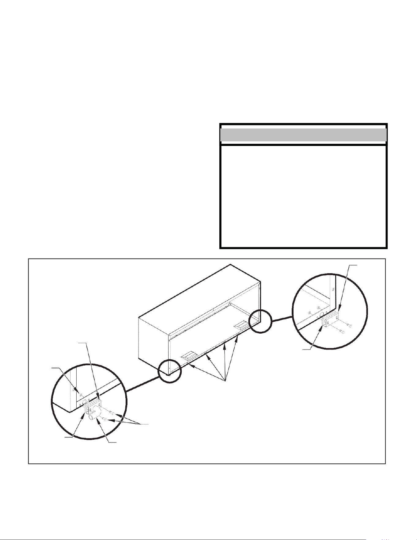
Figure 12
Drain Kit Installation
COVER
PLATE
NUT
MOUNTING
PLATE
FOAM
GASKET
DETAIL A
OVERFLOW
SLOTS
FOAM
GASKET
DETAIL B
SCREWS
½” O.D. TUBE
FRP012
NOTE: The large flange on the mounting plate is positioned at the bottom of the sleeve facing toward the sleeve. The drain tube must be rotated to a
horizontal position to allow for the wall sleeve to be installed into the wall. Once the wall sleeve is installed, return the drain tube to a downward
angle.
41
INSTALLATION
PXGA Standard Grille
12
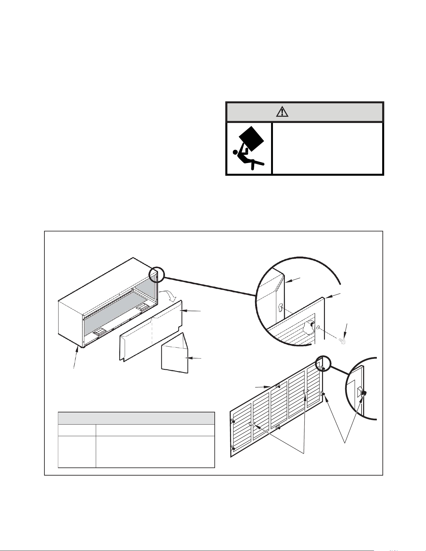
PXGA Standard Grille
Quantity
Description
1
6
6
Stamped Aluminum Grille
Plastic Grommets
#8 x –" Sheet Metal Screws
PXGAStandardGrille
Installation Instructions
1. Remove the center support and weatherboard if still installed in
the sleeve.
2. Insert six plastic grommets into the grille openings from the outside
of the grille as shown in Figure 13.
3. Insert two #8 x ⅜" sheet metal screws (provided) in the top two
outside edge plastic grommets, and tighten them half way into
the grommets.
4. Grasp the grille by the attached plastic handles. Position
it with the condensate drain knockouts facing down.
From inside the building, maneuver the grille through the wall
sleeve and pull toward you until the screw heads are inserted
into the keyhole slots at the top of the wall sleeve. Tighten the
two screws completely.
5. Insert the remaining screws into the remaining holes and tighten
securely.
WARNING
Falling Object Hazard
Not following Installation Instructions for
mounting your air conditioner can result
in property damage, injury, or death.
Figure 13
Standard Grille
WEATHERBOARD
CENTER SUPPORT
WALL
SLEEVE
STANDARD
GRILLE
#8 x 3/8”
SHEET METAL
SCREW
WALL SLEEVE
STANDARD GRILLE
PLASTIC GROMMETS
PLASTIC HANDLES
FRP013
42
INSTALLATION
PXGA Standard Grille
17
CAUTION
Unit Damage Hazard
Failure to follow this caution may result in equipment damage
or improper operation.
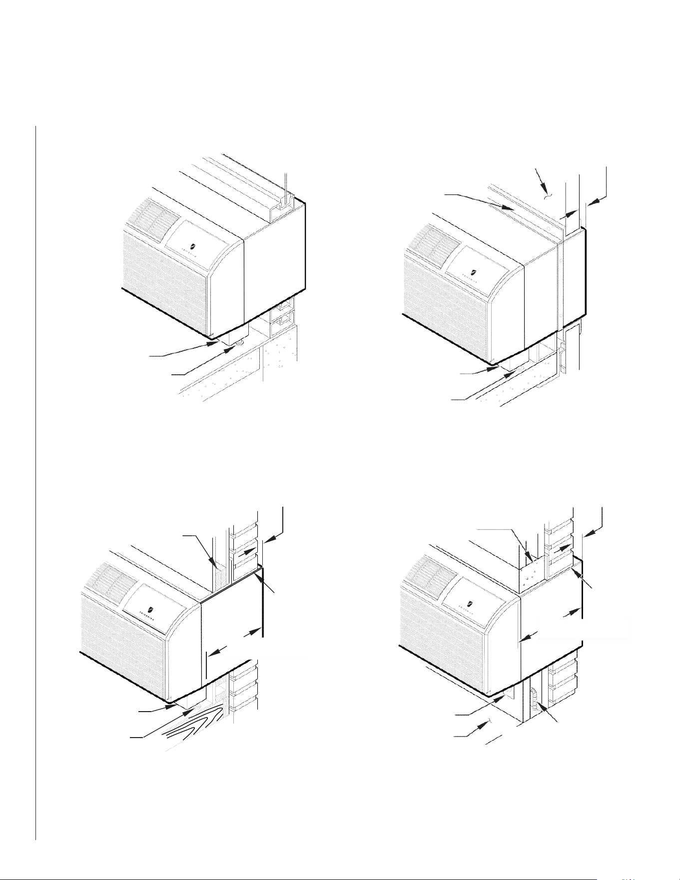
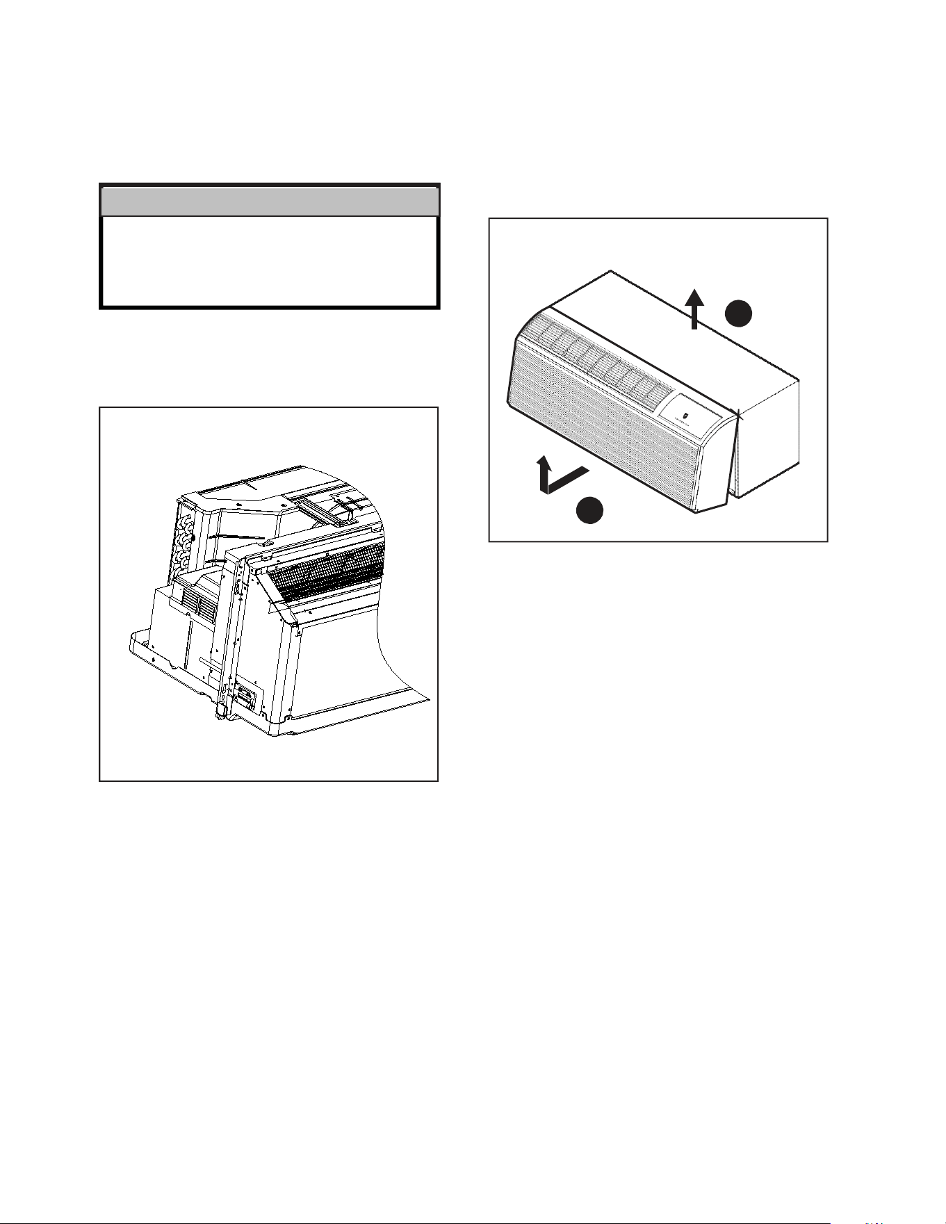
3. Carefully remove shipping tape from the front panel and power
vent door. See Figure 20.
Figure 20
Shipping Tape Location
Figure 21
Removing Front Panel
2
SHIPPING TAPE
FRP020
1
FRP021
4. Remove front panel,see Figure 21.
Pull out at the bottom to release it from the tabs (1). Then lift up (2).
NOTE: If the unit is mounted flush to the floor, the service cord MUST
be rerouted at the bottom of the front cover on the side closest
to the receptacle. A notch MUST be made in the front cover
side where the cord exits the unit. It is the responsibility of
the installer to create an exit notch.
43
INSTALLATION
Remote Control Thermostat Installation
44
INSTALLATION
Front Desk Control Terminal
27
Front Desk Control Terminal
(ONLY FOR UNIT CONTROL)
The Friedrich PV model PTAC has built-in provisions for connection to an
external switch to control power to the unit. The switch can be a central
desk control system.
For front desk control operation, connect one side of the normal open
switch to the R terminal and the other to the FD terminal.
The control logic as below:
(a). Turn ON unit: short R and FD then release for one time within 5s.
(b). Turn OFF unit: short R and FD then release for twice within 5s.
(c). Force unit shut down for one time: short R and FD short over 5s.
NOTE: After forced shut down, you can turn on the unit again by control
panel.
NOTE: The desk control system and switches must be field supplied.
Energy Management
Sometimes known as Front Desk Control, an input is provided so that the
unit can be manually disabled from a remote location. If the unit detects
24Vac on this input, it will automatically turn itself off.If no voltage is
detected on the input , the unit will run normally.
NOTE: It is the installer's responsibility to ensure that all control wiring
connections are made in accordance with the installation
instructions.Improper connection of the thermostat control
wiring and/or tamperingwith the unit's internal wiring can
void the equipment warranty.Other manufacturer's PTACs
and even older Friedrich models may have different control
wire connections.Questions concerning proper connections
to the unit should be directed to Friedrich.
WARNING
Electrical Shock Hazard
Turn off electrical power before service
or installation.
ALL electrical connections and wiring
MUST be installed by a qualified
electrician and conform to the National
Code and all local codes which have
jurisdiction.
Improper connection of the thermostat
control wiring and/or tampering with the
units internal wiring may result in property
damage, personal injury or death.
45
INSTALLATION
Final Inspection & Start-up Checklist
28
Final Inspection & Start-up
Checklist
Inspect and ensure that all components and accessories have been
installed properly and that they have not been damaged during the
installation process.
Check the condensate water drain(s) to ensure they are adequate for
the removal of condensate water, and that they meet the approval of
the end user.
Ensure that all installations concerning clearances around the unit
have been adhered to.Check to ensure that the unit air filter, indoor
coil, and outdoor coil are free from any obstructions.
Ensure that the entire installation is in compliance with all applicable
national and local codes and ordinances that have jurisdiction.
Secure components and accessories, such as the chassis, decorative
front cover and control door.
Start the unit and check for proper operation of all components in
each mode of operation.Instruct the owner or operator of this units
operation, and the manufacturer’s recommended routine maintenance
schedule.
NOTE: A log for recording the dates of maintenance and/or service
is recommended.
Present the owner or operator of the equipment with the Installation
& Operation manual, all accessory installation instructions, and the
name, address and telephone number of the Authorized Friedrich
Warranty Service Company in the area for future reference if
necessary.
Routine Maintenance
To ensure proper unit operation and life expectancy the following mainte-
nance procedures should be performed on a regular basis.
WARNING
Electrical Shock Hazard
Unplug Unit or turn off electrical power
to unit prior to performing maintenance
procedures
Failure to do so can result in electrical
shock or death
Front Panel Air Filter
To ensure proper unit operation, the air filters should be cleaned at least
monthly, and more frequently if conditions warrant.The unit must be
turned off before the filters are cleaned.
To remove the air filters,filter grasp the top of the filters and lift out of the
front cabinet.Reverse the procedure to reinstall the filters.
Clean the filters with a mild detergent in warm water, and allow them to
dry thoroughly before reinstalling.
Fresh Air Filter
The fresh air filter should be cleaned or replaced after 3 months of use
for maximum effectiveness The unit must be turned off before the filters
are replaced.
To replace the fresh air filters,drag the unit from wall sleeve and pull the
tape sticked to fresh air filter.
Coils & Chassis
NOTE: Do not use a caustic coil cleaning agent on coils or base pan.
Use a biodegradable cleaning agent and degreaser.The use of harsh
cleaning materials may lead to deterioration of the aluminum fins or the
coil end plates.
The indoor coil and outdoor coils and base pan should be inspected pe-
riodically (annually or semi-annually) and cleaned of all debris (lint, dirt,
leaves, paper, etc ) as necessary. Under extreme conditions, more frequent
cleaning may by required.Clean the coils and base pan with a soft brush
and compressed air or vacuum.A pressure washer may also be used,
however, you must be careful not to bend the aluminium fin pack.Use a
sweeping up and down motion in the direction of the vertical aluminium
fin pack when pressure cleaning coils.
NOTE: It is extremely important to insure that none of the electrical
and/or electronic parts of the unit get wet. Be sure to cover all electrical
components to protect them from water or spray.
Decorative Front
The decorative front and discharge air grille may be cleaned with a mild
soap or detergent.Do NOT use solvents or hydrocarbon based cleaners
such as acetone, naphtha, gasoline, benzene, etc , to clean the decorative
front or air discharge grilles.
Use a damp (not wet) cloth when cleaning the control area to prevent
water from entering the unit, and possibly damaging the electronic control.
Fan Motor & Compressor
The fan motor & compressor and are permanently lubricated, and require
no additional lubrication.
Wall Sleeve
Inspect the inside of the wall sleeve and drain system periodically (annually
or semi-annually) and clean as required.
Under extreme conditions, more frequent cleaning may be necessary.
Clean both of these areas with an antibacterial and antifungal cleaner.
Rinse both items thoroughly with water and ensure that the drain outlets
are operating correctly. Check the sealant around the sleeve and reseal
areas as needed.
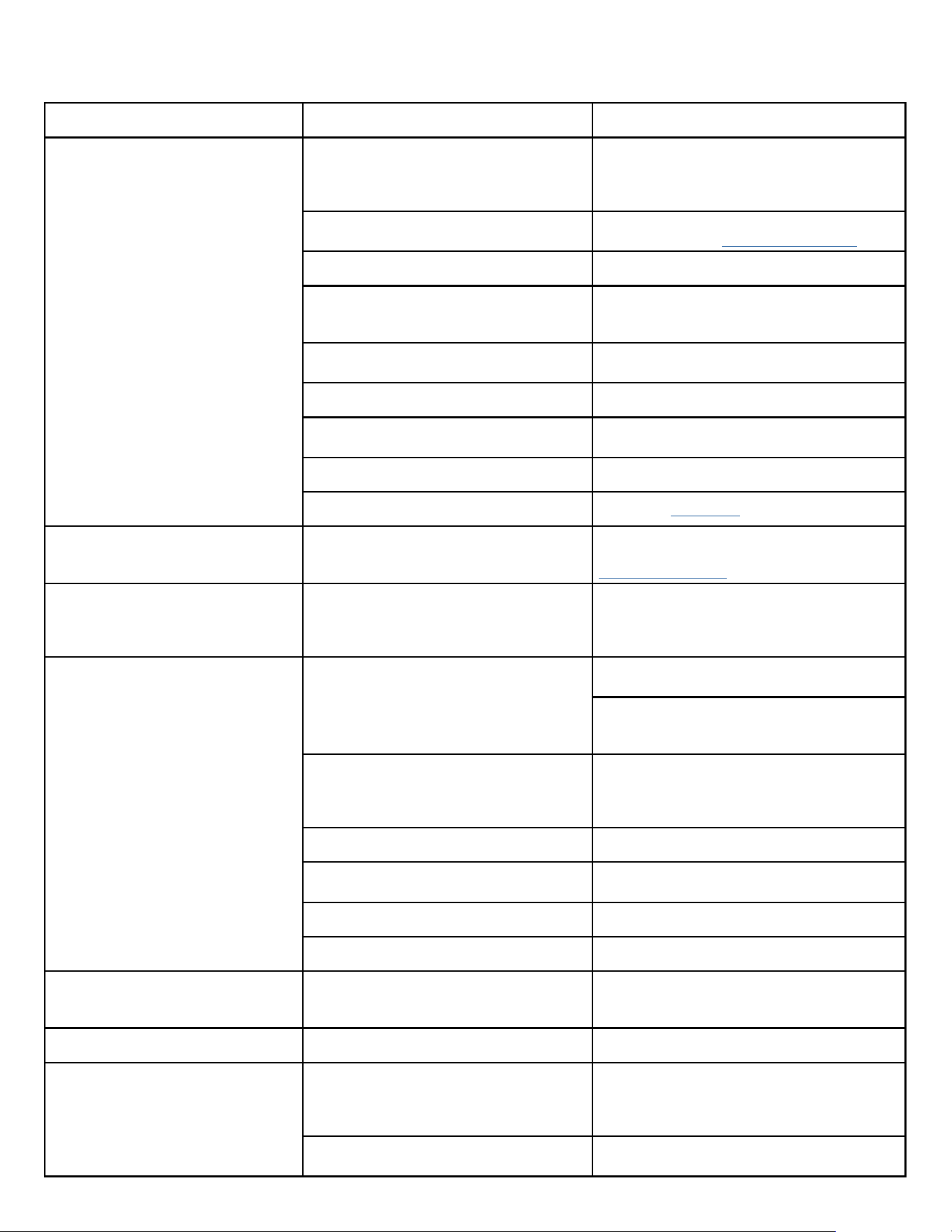
46
TROUBLESHOOTING
Basic Troubleshooting
Malfunction Possible Reasons Solution
Start Failure
Unit does not have power; Power line damaged
or power not available.
"Check the indicator LED on the LCID power head,
it should be lit up, if not, push the RESET button,
if still no voltage, but power grid has output, you
need to change the power cord."
Power cord protection trip.
Check the power cord for damage, push the RESET
button. If not solved, replace the power cord.
Power cord isn’t plugged in correctly. Plug in cord correctly.
PCB fuse is broken.
Check if any load (in fan, out fan, reversing valve,
power transformer) has a short circuit. Eliminate
the error and replace the fuse with the same type.
Bad contact between main board and control
panel.
Check the contact wires, make sure all contact
well.
Compressor delay start. It’s normal, compressor will start after 3 minutes
Power fail protection.
When power on, because of auto-restart, unit will
delay starting in 120~240s
Unit in protection mode. Please check the ERROR CODE
Main board or Control panel is bad. Replace the main board or control panel
Control panel does not work
When the unit is switched to 24V remote
thermostat or 12V smart controller, the control
panel will not be functioning.
If you need to use control panel to take control,
you need to switch the control master. See the
ADVANCED SETTINGS section.
Indoor fan/outdoor fan does not function
or runs slowly
Fan is locked by something or the power wires
are poorly connected; fan capacitor is poorly
connected; fan capacitor is out of service life.
Disconnect the power cord, check whether the fan
can run smooth by hand or other tools, whether
motor wire is connected well. If fan has slow
running speed replace capacitor.
Not cooling/heating adequately
Something is blocking the indoor/outdoor air
outlet.
Make sure that there are no obstacles at the
indoor/outdoor air outlet.
Make sure that the grill is suitable for the unit,
inappropriate grill will cause the compressor to
fault; make sure that the grill has more than 70% .
Set unsuitable temperature.
Set higher/lower temperature by the control
board. NOTE: temperature setting restriction
will restrict the setting temperature. See the
ADVANCED SETTINGS section.
Indoor air filter is dirty. Should clean the filter at least every month.
Room is hot/cold.
Let unit run a little longer that room temperature
will be lower/higher.
Heat leakage between indoor and outdoor. Block the leakage place.
Indoor coil not cold/heat. Charge the refrigerant.
Unit has noise
"Some moving parts of the unit are loose
causing bad vibration.
Something in the air way."
Make sure that all moving parts are assembled
well, and nothing is in the air way.
Bad smell when heating The dust on the E-heater is heating. The bad smell will disappear a little later.
Outlet temperature is not always cooling/
heating
Outlet temperature is not high enough when
heating by heat pump.
When outdoor ambient temp is low, the heat pump
will not be able to offer enough heat. Soon after
that, the E-heater will come on to heat.. Possible
Maintenance is required.
Fan stops when cooling/heating.
It is normal when the CONSTANT FAN is OFF. You
can enable the CONSTANT FAN.
Figure 711
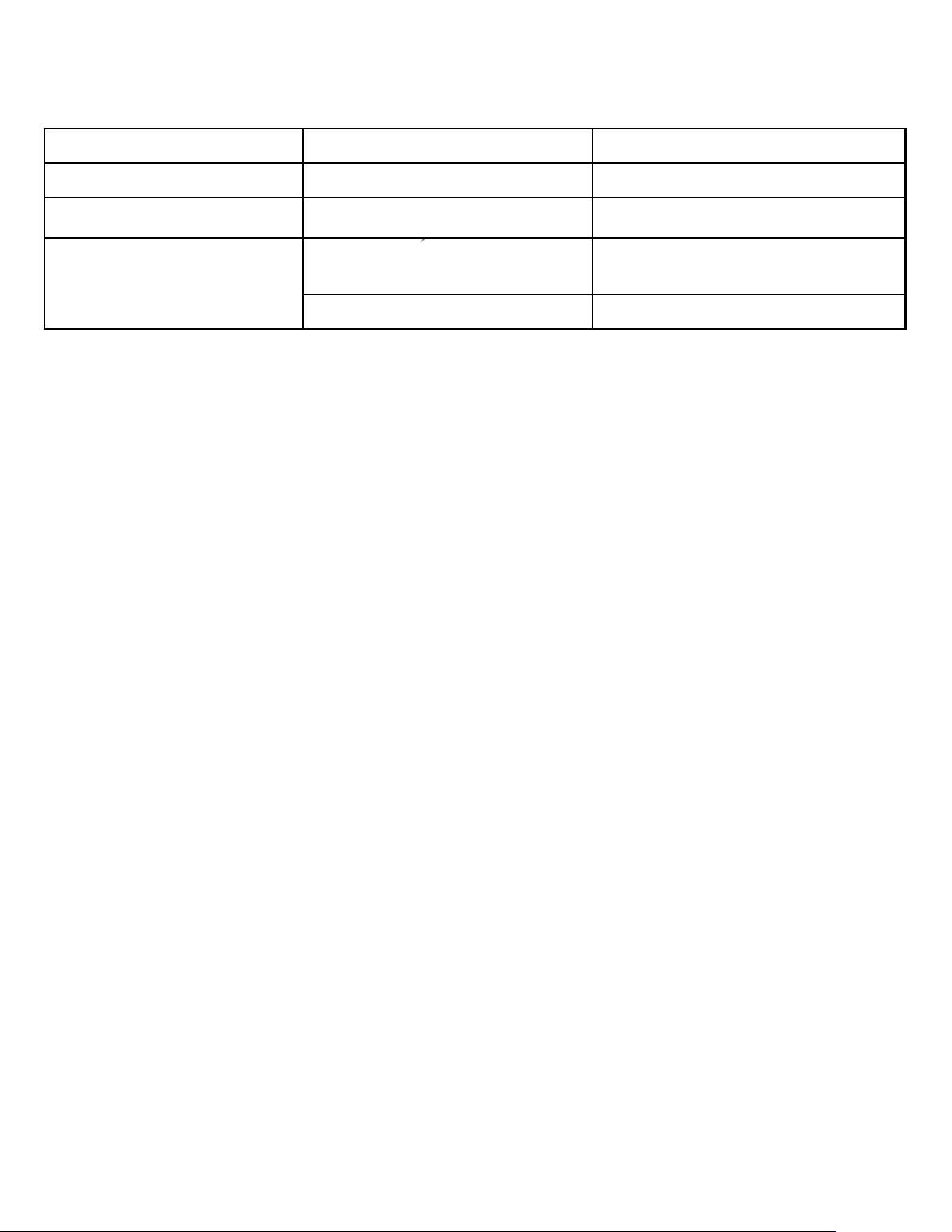
47
TROUBLESHOOTING
Basic Troubleshooting
Figure 711
Malfunction Possible Reasons Solution
Water dripping outdoors. Drain pipe kit not installed. Install the drain pipe kit.
Water dripping indoors. Wall sleeve is not installed correctly.
Install the wall sleeve according to the installation
manual.
Indoor coil freeze
Outdoor temperature is too low in cooling
mode.
When outdoor temperature is drop to 55°F (12.8°)
or below, it will cause that indoor coil to freeze.
Open the fresh air door, and running at fan mode.
Filter is dirty. Clean the filter to recover the normal air flow
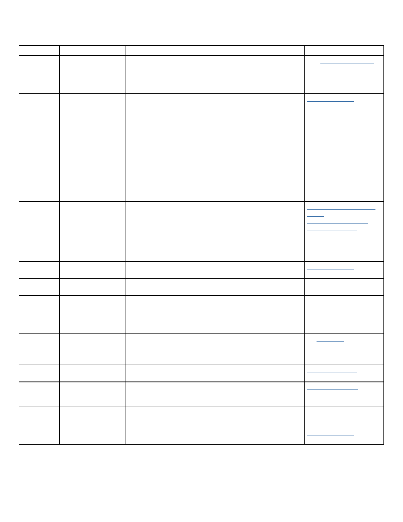
48
TROUBLESHOOTING
Error code and solutions
ERROR CODE Meaning Solutions Click link for reference
E1 Communication Error
between Power,
IPM, Main, & or
Display electronic
boards+B2:C14
Check all Communication Cables; MOD_Com, MB_Com, Display_com&
Power Relay_com.
See “Unit does not operate”
in troubleshooting section”
E2 Indoor Temp Sensor
Open/Shorted
Check if properly connected.
Check resistance values.
Check for loose wires/broken wires in Molex connectors.
Check Thermistors
E3 Indoor Evaporator Coil
Sensor Open/Shorted
Check if properly connected.
Check resistance values.
Check for loose wires/broken wires in Molex connectors.
Check Thermistors
E4 Indoor Supply Air
Sensor Open/Shorted or
Overheating of electric
heater
Check if properly connected.
Check resistance values.
Check for loose wires/broken wires in Molex connectors.
Check for Over Heating.
Check for low air flow or no air flow due to evap coil clog.
Evap fan motor compromised, Fan Capacitor compromised, blower
wheel compromised.
Heater relays compromised.
Check Thermistors
Check Heater control
E5 IPM Board in protection
mode
Check if compressor wiring is incorrect, IPM PCB compromised,
Power PCB compromised, or if compressor compromised.
Check for airflow obstructions.
Check CN 13 on Power PCB for 15VDC at pins 1 and 2.
Check compressor coil resistance. Check IPM PCB for arcing or odors
of overheating.
Check and monitor power supply stability and ensure proper NEC
code grounding at the main breaker and power supply.
Remove IPM PCB (Inverter
Board)
Power PCB Identification
Compressor Checks
Remove Power PCB
E6 Outdoor Temp Sensor
Open/Shorted
Check if properly connected, check resistance values, check for loose
wires/broken wires in Molex connectors.
Check Thermistors
E7 Outdoor Condenser Coil
Sensor Open/Shorted
Check if properly connected, check resistance values, check for loose
wires/broken wires in Molex connectors.
Check Thermistors
E8 Communication failure
to wall controller
Check all connectors between PTAC and wall controller are properly
connected. Shutdown unit, and then remove power plug from wall
or open fuse/ circuit breaker. Wait 3 or 4 minutes and then reapply
power and restart the unit. If E8 error persists, contact Friedrich
Technical Support at (1-800-541-6645). for further assistance.
EC Compressor attempted
to start but failed to
start
Check Dip Switch SW2 on Main Board is correct for the BTU of the unit
model.
Check Compressor wiring is properly connected.
Check compressor for Short/Ground, Check IPM Board.
See Operation section for
details on dip switches
Compressor Checks
EH EEPROM Error Replace Main Board, Check for compromised electrical wires to Main
Board
Replace Main Board
EF 30 amp power cord
installed on PVH09 (230
or 265 volt) Not Allowed
Replace the power cord to 15A or 20A supply cord as required. See
Accessory section.
Replace Power Cord
P1 Cooling or Heating
overload
Check for low air flow or no air flow due to evaporator or condenser
coil blocked with debris.
Evap/Cond motor fan motor compromised, Fan Capacitors
compromised, blower wheel/fan blade compromised.
Check Resistance values for indoor and Outdoor coil thermistors.
Check indoor fan motor
Check outdoor fan motor
Check Fan Capacitors
Check Thermistors
Figure 712
49
TROUBLESHOOTING
Error code and solutions
Figure 712
ERROR CODE Meaning Solutions Click link for reference
P2 IPM Over Heat or Over
Current Protection
invoked
Check for low air flow or no air flow due to evaporator or condenser
coil blocked with debris.
Evap/Cond motor fan motor compromised, fan Capacitors
compromised, blower wheel/fan blade compromised.
Check Dip Switch SW2 on Main Board is correct for the BTU of the unit
model.
Check Compressor wiring is properly connected, Check compressor
for Short/Ground, Check IPM PCB.
See Operation section for
details on dip switches.
Check indoor fan motor
Check outdoor fan motor
Check Fan Capacitors
Check Compressor
Check IPM PCB
P4 Compressor Discahrge
Over Heat Protection
invoked
Check for low air flow or no air flow due to evaporator or condenser
coil blocked with debris.
Evap/Cond motor fan motor compromised, Fan Capacitors
compromised, blower wheel/fan blade compromised.
Check Dip Switch SW2 on Main Board is correct for the BTU of the unit
model
Check Compressor wiring is properly connected, Check compressor
for Short/Ground, Check IPM Board,
See Operation section for
details on dip switches.
Check indoor fan motor
Check outdoor fan motor
Check Fan Capacitors
Check Compressor
Check IPM PCB
P7 DC Over/Under
Supply Power Voltage
Protection invoked
Check for low air flow or no air flow due to evaporator or condenser
coil blocked with debris.
Indoor blower/ outdoor fan compromised, fan capacitors
compromised. Blower wheel/ fan blade compromised.
Check dip switch SW2 on main pcb is correct for the BTU of the model.
Check compressor wiring is properly connected. Check compressor
for short. Check IPM PCB.
Check Power Supply is within the required power supply tolerances
of +/- 10%
Check and monitor power supply stability and ensure proper NEC
code grounding at the main breaker and power supply.
See Unit does not Operate
Check indoor fan motor
Check outdoor fan motor
Check Fan Capacitors
Check Compressor
Check IPM PCB
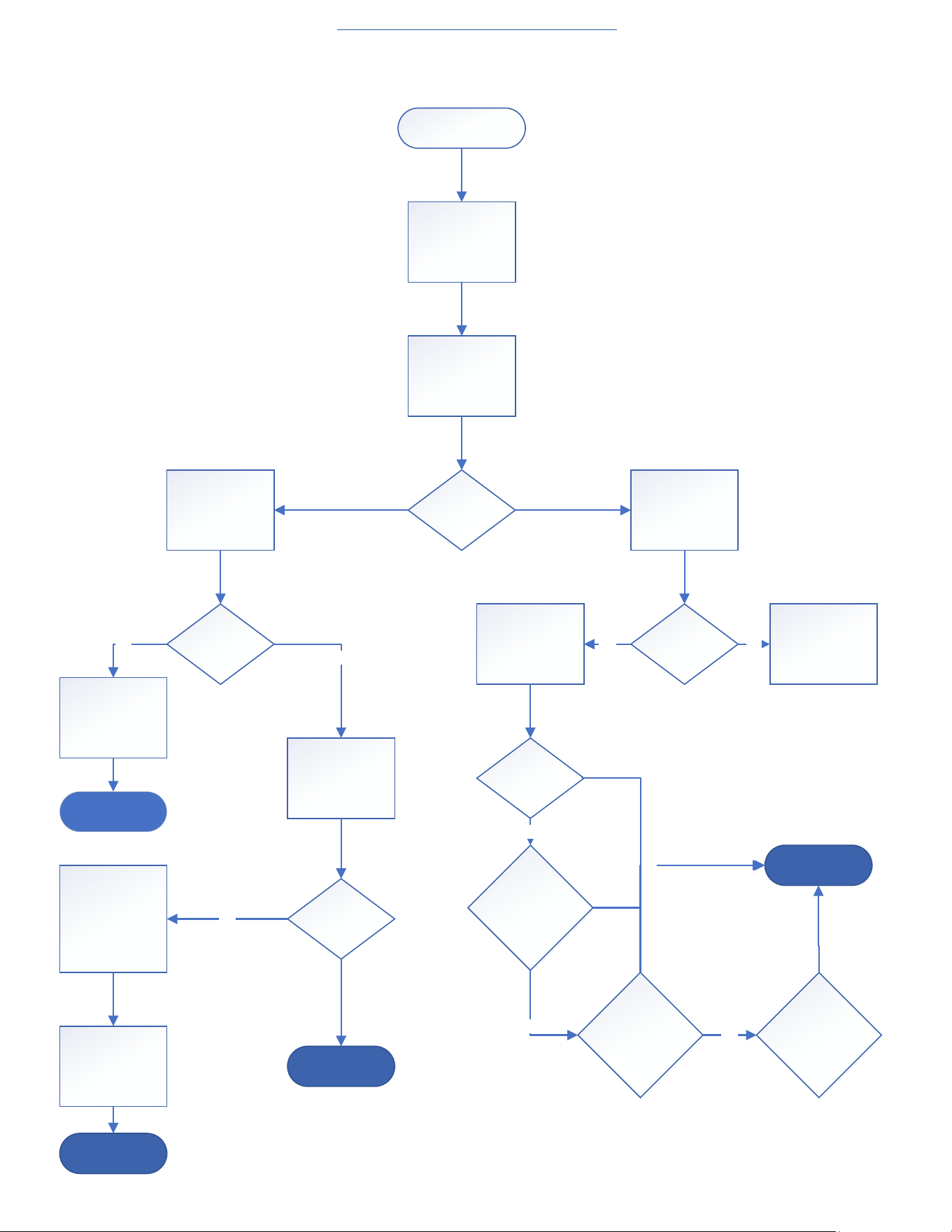
50
TROUBLESHOOTING
Unit Does Not Operate
Unit Does Not O perate
Remove Front Panel
(Figure 501)
Open Electrical Box
(Figure 505)
Check L1 and L2 for
line voltage
(220-265v) on
Power PCB
Che ck L CDI Unit
power supply cord
for tripped circuit
Trace back source
power to tripped
breaker or open
fuse
Is L ine voltage
Present
Check the fuses on
the power PCB for
continuity with multi
meter
Is power Cord
tripped
Reset cord and test
uni t for prope r
operation
Does Power c ord
trip again
Check power cord
in cludi ng power
board L1 and L2
conne ction for
proper connection
or damage
Correct power
supply connections
or replace Power
cord
YES
NO
YES
End Pro ces s
End Pro ces s
En d Pro ces s
Is the fuse openReplace f use
Go to Next page and
continue
troubleshooting
YES NO
Re tes t unit
Does fuse blow
again?
Replace Power PCB
and Rete st
Does fuse blow
again?
Replace IPM PCB
and Retest
Does fuse blow
again?
Replac e M ain PCB
END PROCESS
YES
YES
YES
NO
Figure 713
Return to Error Codes and Solutons
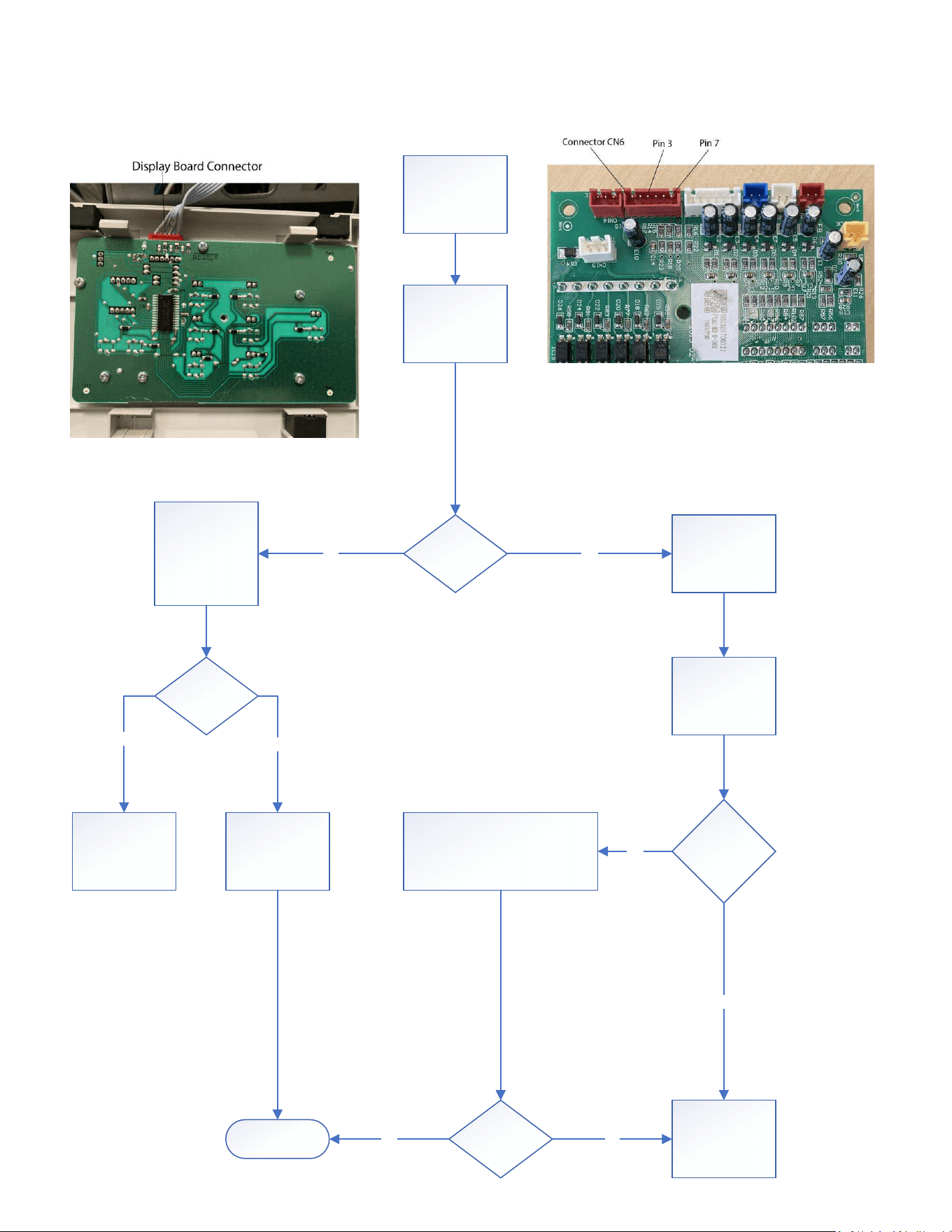
51
TROUBLESHOOTING
Unit Does Not Operate
Disconnect Display
Connector CN6 on
top of Main PCB
Set multi meter do
read low voltage DC
and pl ace Mult i
Meter leads on pins
3 and 7.
Is Fluctuating
0-6Vdc Present?
Set mul ti me ter to
read continuity.
Check all wires on
disp lay board
conne ctor c able to
CN6 plug for pin to
pin continuity.
Are any wi re s
showing open
(OL)?
Replace Dis play
Boa rd
Replace Connector
cable
Che ck al l wi ring and
comms cable
conne ctors fr om
Main PCB to the
Power PCB
Ensure all
conne ctors are
und ama ged, fully
connected and fully
engaged.
Fix any issues
Reference wiring diagram (figure
801) Main PCB Diagram (Figure 709)
Power PCB Diagram (Figure (710)
Any loose,
damaged, or
disconnected
c onne ct ors?
Is Fluctuating
0-6Vd c Pre sent?
NO YES
YES
YES
END PROCESS YES
No
Continue
troubleshooting
No
NO
Figure 713
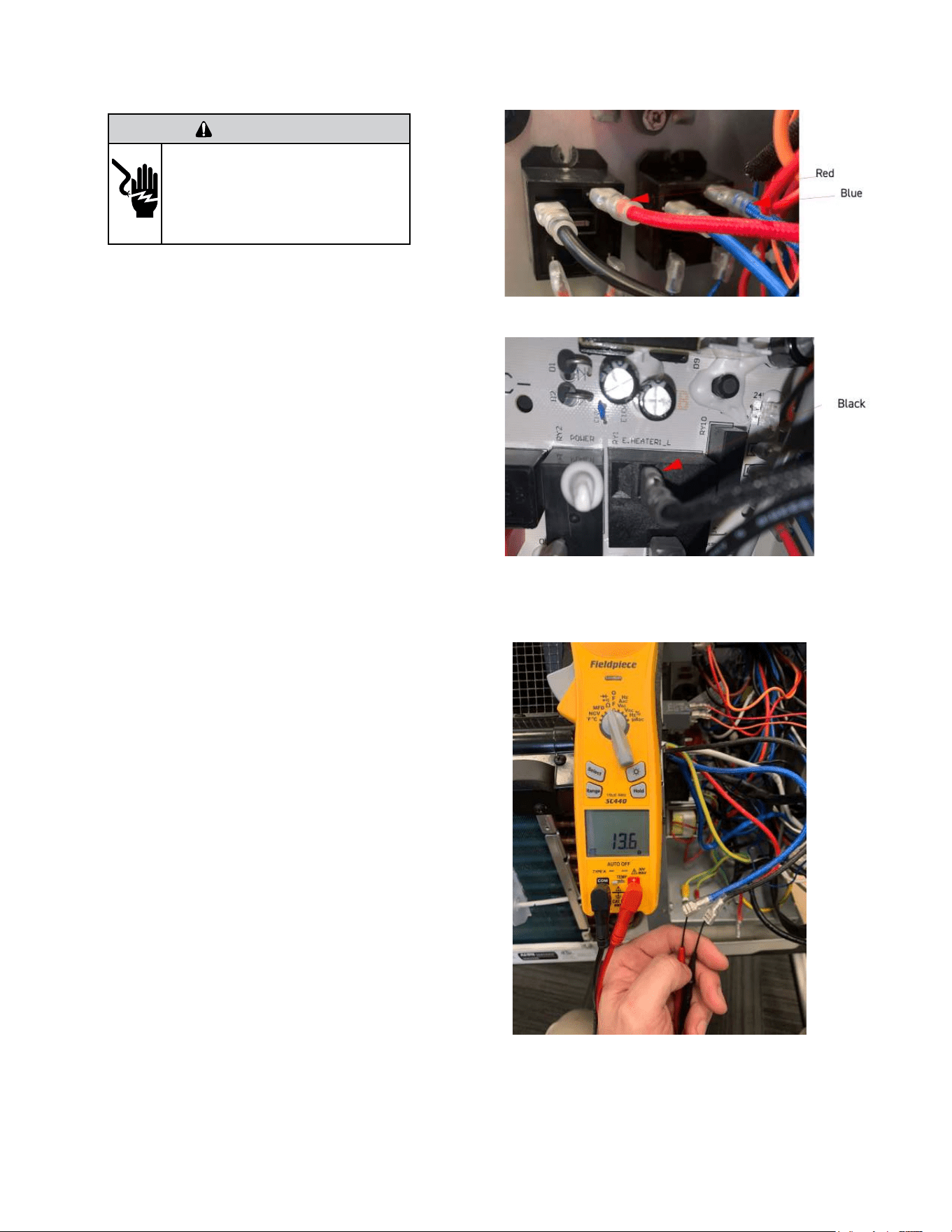
52
TROUBLESHOOTING
Check Heater Coil
The unit is equipped with a universal E-heater, which contains two
independent heating elements. Two limit switches are incorporated
into the heater assembly. The primary opens at 160°F and closes at
130°F. The secondary’s open temp is 221°F. They can not be replaced
independently. If they are found to be faulty the entire heater assembly
must be replaced as a unit. The 9K BTU unit incorporates a 2.5 kW and
a 1.0 kW element. The 12K BTU unit incorporates a 3.5 kW and a 1.5 kW
element.
Gain Access to Main PCB (logic) board
1. Remove front panel (Figure 501).
2. Remove User Interface (Figures 502 thru 504).
3. Open electrical Control Box (Figure 505)
4. Disconnect Red and Blue wires from the Heater relays (Figure 714)
5. Disconnect black wire from Power PCB (Figure 715)
Testing The Heating Element
Testing of the elements can be made with an ohmmeter across the
terminals after the 3 heater wires have been disconnected.
Readings should always been taken when coil is cold.
The 9K BTU unit incorporates a 2.5 kW and 1.0 kW heater coils.
1) Check 2.5 kW coil
Blue (Heater Common) to Black (Heater 1)
230v = ohms +-3%
265v = ohms +- 3%
2) Check 1.0 kW coil
Blue (Heater Common) to Red (Heater 2)
230v = ohms +-3%
265v = ohms +- 3%
The 12K BTU unit incorporates a 3.5 kW and 1.5 kW heater coils.
1) Check 3.5 kW coil
Blue (Heater Common) to Black (Heater 1)
230v = ohms +-3%
265v = ohms +-3%
2) Check 1.5 kW coil
Blue (Heater Common) to Red (Heater 2)
230v = ohms +-3%
265v = ohms +-3%
If a reading is open or out of tolerance replace the heater assembly.
Reconnect wires and operate heat to place electric heater in demand-
See sequence of operation for details.
Check 230/265v at output terminals on heater relays. If 230/265 volts is
present and heater element does not operate correctly, replace heater
assembly. If 230/265 volts in not present, proceed to figure 717 (Check
electric heater control)
Figure 716 (Check Heater Coil Resistance)
Figure 714 (Check Heater Coil Resistance)
Figure 715 (Check Heater Coil Resistance)
WARNING
ELECTRIC SHOCK HAZARD
Turn off electric power before service or
installation. Extreme care must be used, if it
becomes necessary to work on equipment with
power applied.
Failure to do so could result in serious injury or
death.
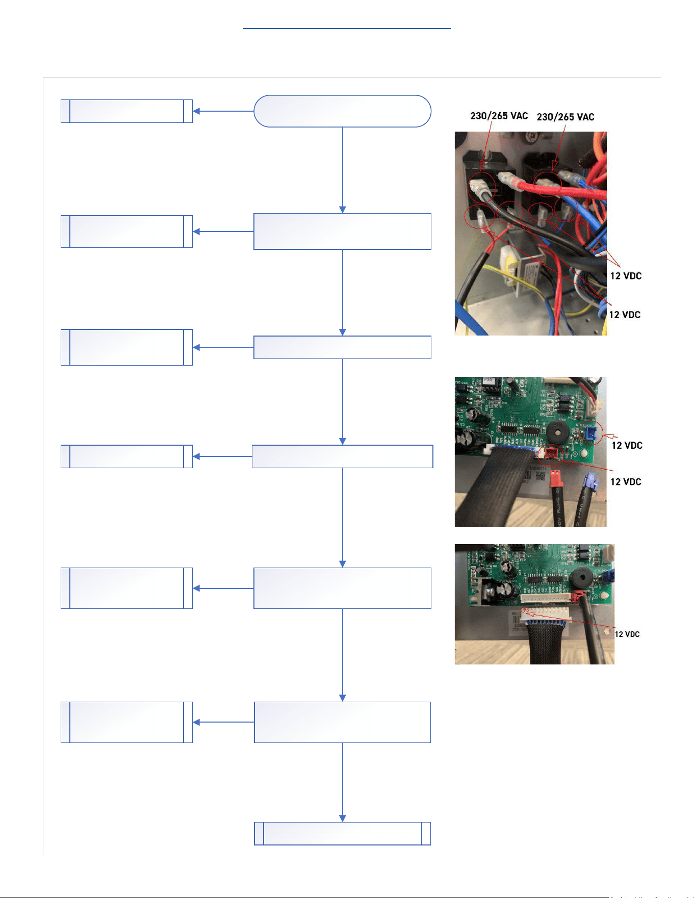
53
TROUBLESHOOTING
Check Electric Heater Control
Figure 717
Return to Error Codes and Solutions
Check Heater Assembly.
Refer to Figures 714-716 on previous page.
Does Heater Assembly check good?
Check for 12 vdc at heater relays.
Is 12 VDC Present?
Check CN2 and CN21 on Main PCB for 12 vdc.
Is 12 VDC Present?
Check for consistent 12-14 vdc at power relay
connector on main PCB. Monitor voltage for a few
minutes to ensure voltage does not drop off.
Is 12 VDC Present?
Replace Heater Assembly.
Check for 230/265v across relay 1 black and relay 2
blue wire on com terminals.
Is 230/265 present?
Check line voltage connec�ons at
line block. Repair as required.
Replace Relays as required.
Replace or repair cables.
Replace Main PCB.
Check for con�nuity end to end on power relays
cable.
Does Cable check good?
Replace Power relays cable.
Replace Power PCB.
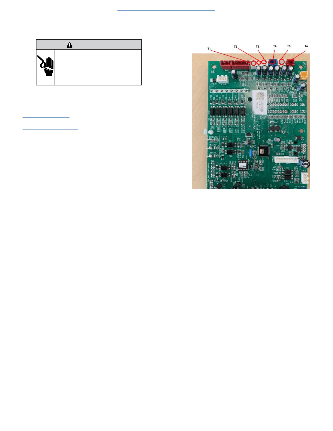
54
TROUBLESHOOTING
Check Thermistors
Gain Access to Main PCB (logic) board
1. Remove front panel (Figure 501).
2. Remove User Interface (Figures 502 thru 504).
3. Open electrical Control Box (Figure 505).
4. Using a multi-meter ohm across applicable pins for the sensor you
are checking.
5. Refer to thermistor charts in Appendix for resistance and temperature
deviation.
5k Indoor ambient temperature (T1) Figure 719
5k Indoor coil temperature (T2) Figure 719
5k Outdoor coil temperature (T3) Figure 719
5k Outdoor ambient temperature (T4) Figure 719
50k Compressor discharge temp (T5) Figure 720
5k Indoor outlet air temperature (T6) Figure 19
6. Replace sensor if open or if resistance values deviate by more than
10% of the listed values.
Figure 719 (Thermistor Connections on Main PCB)
Figure 718
Return to Error Codes and Solutons
WARNING
ELECTRIC SHOCK HAZARD
Turn off electric power before service or
installation. Extreme care must be used, if it
becomes necessary to work on equipment with
power applied.
Failure to do so could result in serious injury or
death.
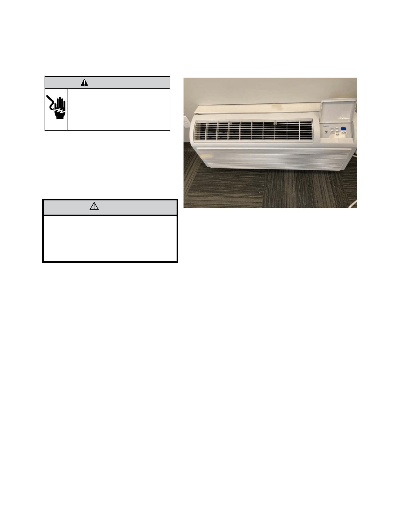
55
UNIT DISASSEMBLY AND COMPONENT REPLACEMENT
Remove Chassis
The Front Panel needs to be removed prior to any repair or
troubleshooting procedures.
1. Front panel is removed by lifting up and rotating back
and down.
2. Remove 4 mounting screws and slide unit out of sleeve.
Figure 501 (Chassis Removal)
CAUTION
Unit weighs approximately 120 pounds.
Use caution when removing to prevent
personal injury or damage to the equipment.
WARNING
ELECTRIC SHOCK HAZARD
Turn off electric power before service or
installation. Extreme care must be used, if it
becomes necessary to work on equipment with
power applied.
Failure to do so could result in serious injury or
death.
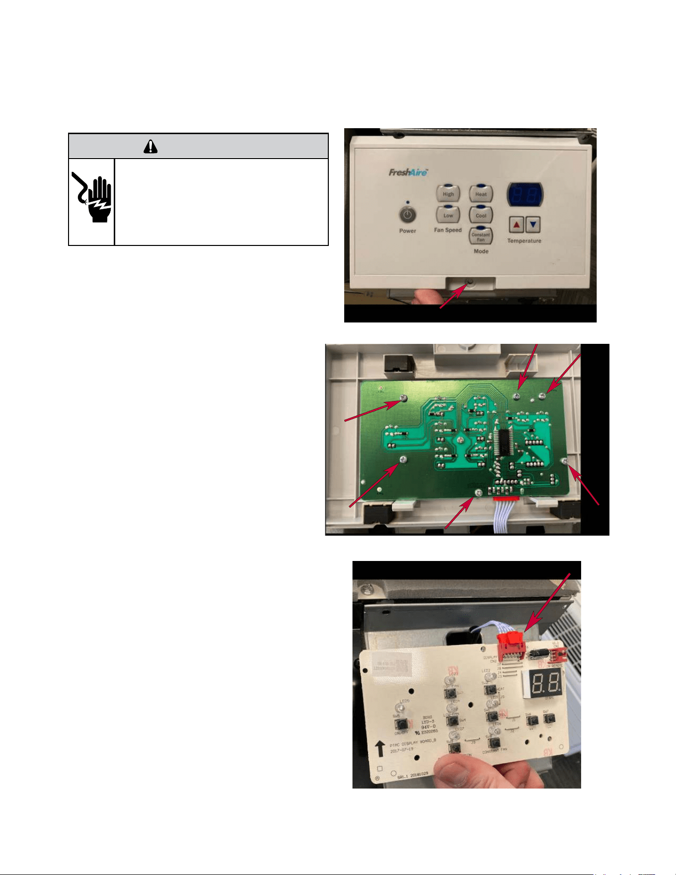
56
UNIT DISASSEMBLY AND COMPONENT REPLACEMENT
Remove User Interface
1. Remove 1 screw securing User Interface to
the control box. (Figure 502)
2. Remove 6 screws attaching display board to
user interface. (Figure 503)
3. Disconnect plug. (Figure 504)
Figure 502 (User Interface Removal)
Figure 503 (User Interface Removal)
Figure 504 (User Interface Removal)
WARNING
ELECTRIC SHOCK HAZARD
Turn off electric power before service or
installation. Extreme care must be used, if it
becomes necessary to work on equipment with
power applied.
Failure to do so could result in serious injury or
death.
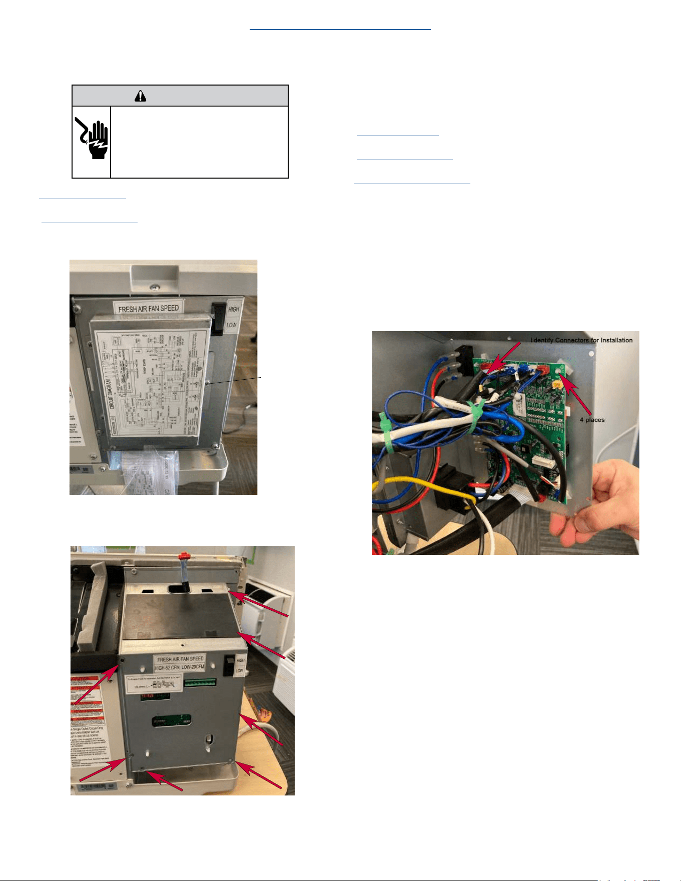
57
UNIT DISASSEMBLY AND COMPONENT REPLACEMENT
Open Electrical Control Box
1. Remove front panel (Figure 501).
2. Remove User Interface (Figures 502 thru 504).
3. Remove fireproof cover. (See figure 505.1)
Remove screw
(3 places)
Figure 505.1
4. Remove 7 screws.(Figure 505)
Figure 505.2
5. Unhinge electrical box.
Remove Main PCB (logic) Board
1.
Remove front panel (Figure 501).
2. Remove User Interface (Figures 502 thru 504).
3. Open electrical Control Box (Figure 505).
4. Snip wire ties to loosen wire bundles. (Figure 506).
NOTE: It is a good practice to take pictures of the wiring
connections to facilitate reinstallation.
5. Disconnect wire connectors from Main PCB (logic) board one at a
time. Identify plugs for reinstallation.
6. Remove 4 standoffs by pinching tip and applying slight upwards
pressure to the board.
Figure 506
WARNING
ELECTRIC SHOCK HAZARD
Turn off electric power before service or
installation. Extreme care must be used, if it
becomes necessary to work on equipment with
power applied.
Failure to do so could result in serious injury or
death.
Return to Basic Troubleshooting
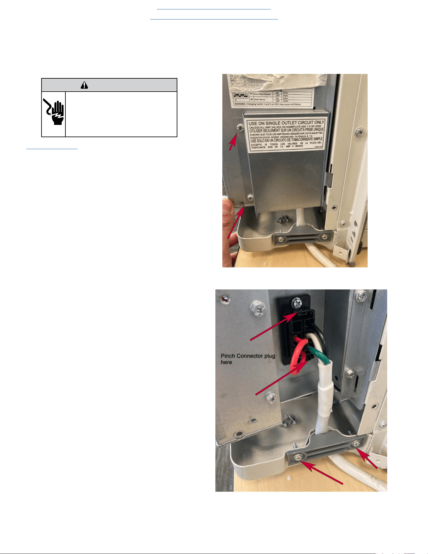
58
UNIT DISASSEMBLY AND COMPONENT REPLACEMENT
Remove Power Cord
1. Remove front panel (Figure 501).
1. Remove power cord access panel located on right side of
control box(2 screws) Figure 507)
2. Pinch retainer clips on top and bottom of power cord plug
to disconnect (Figure 508).
3. Remove cord grommet (2 screws).
Figure 507 (Remove Power Cord)
Figure 508 (Remove Power Cord)
WARNING
ELECTRIC SHOCK HAZARD
Turn off electric power before service or
installation. Extreme care must be used, if it
becomes necessary to work on equipment with
power applied.
Failure to do so could result in serious injury or
death.
Return to Basic Troubleshooting
Return to Error Codes and Solutions
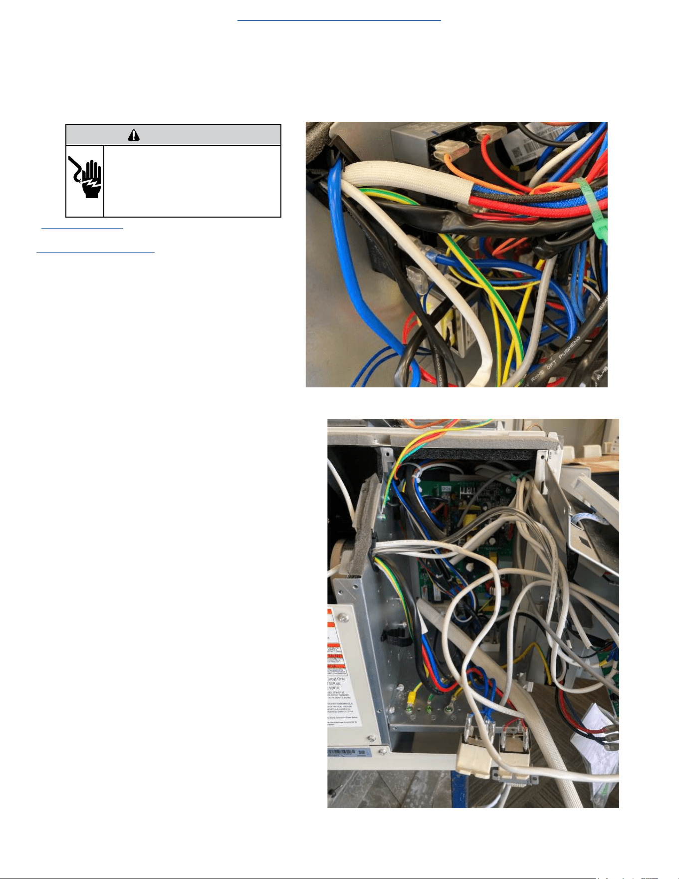
59
UNIT DISASSEMBLY AND COMPONENT REPLACEMENT
Remove Power PCB
1. Remove front panel (Figure 501).
3. Open electrical Control Box (Figure 505).
4. Snip wire ties to loosen wire bundles (Figure 509).
NOTE: It is necessary to unmount components to gain
access for Power PCB removal.
5. Remove 1 capacitor, 2 heater board relays, and 1 trans-
former but DO NOT disconnect connections (Figure 510).
NOTE: It is a good practice to take pictures of the
wiring connections to facilitate reinstallation.
6. Disconnect wire connectors from Power PCB (Power
Board) one at a time. and identify plugs for reinstallation .
7. Remove Power PCB (Power Board) (4 screws).
Figure 509 (Remove Power PCB)
Figure 510 (Remove Power PCB )
WARNING
ELECTRIC SHOCK HAZARD
Turn off electric power before service or
installation. Extreme care must be used, if it
becomes necessary to work on equipment with
power applied.
Failure to do so could result in serious injury or
death.
Return to Error Codes and Solutions
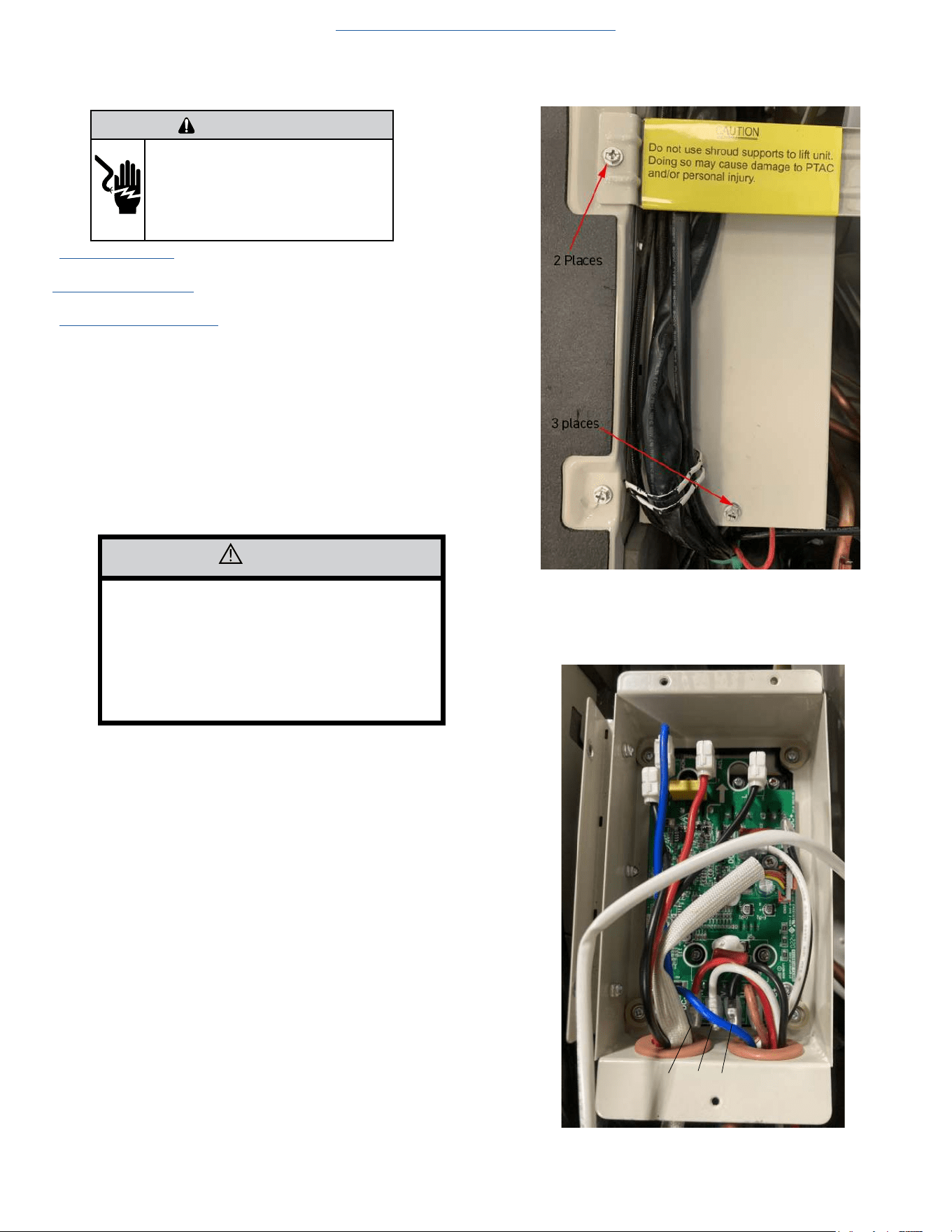
60
UNIT DISASSEMBLY AND COMPONENT REPLACEMENT
Remove IPM PCB (Inverter Board)
1. Remove front panel (Figure 501).
2. Remove User Interface (Figures 502 thru 504).
3. Open electrical Control Box (Figure 505).
4. Disconnect CN 13 from the Power PCB.
5. Remove Chassis from Wall (Figure 501).
6. Remove shroud support (2 screws) (Fig 512).
7. Remove IPM PCB Cover (3 screws) (Fig 512).
NOTE: It is a good practice to take pictures of the wiring
connections to facilitate reinstallation.
8. Disconnect all wires. (Fig 513)
8) Remove 4 mounting screws (Figure 513).
Figure 512 (Remove IPM PCB)
Figure 513 (Remove IPM PCB)
CAUTION
IPM PCB is attached to a heavy heat sink with
thermal paste or a thermal mat which is
required to dissipate heat from the IPM PCB.
Use care when removing.
PCB needs to drop down through housing.
It can fall and be damaged if care is not taken.
Return to Error Codes and Solutons
W V U
WARNING
ELECTRIC SHOCK HAZARD
Turn off electric power before service or
installation. Extreme care must be used, if it
becomes necessary to work on equipment with
power applied.
Failure to do so could result in serious injury or
death.
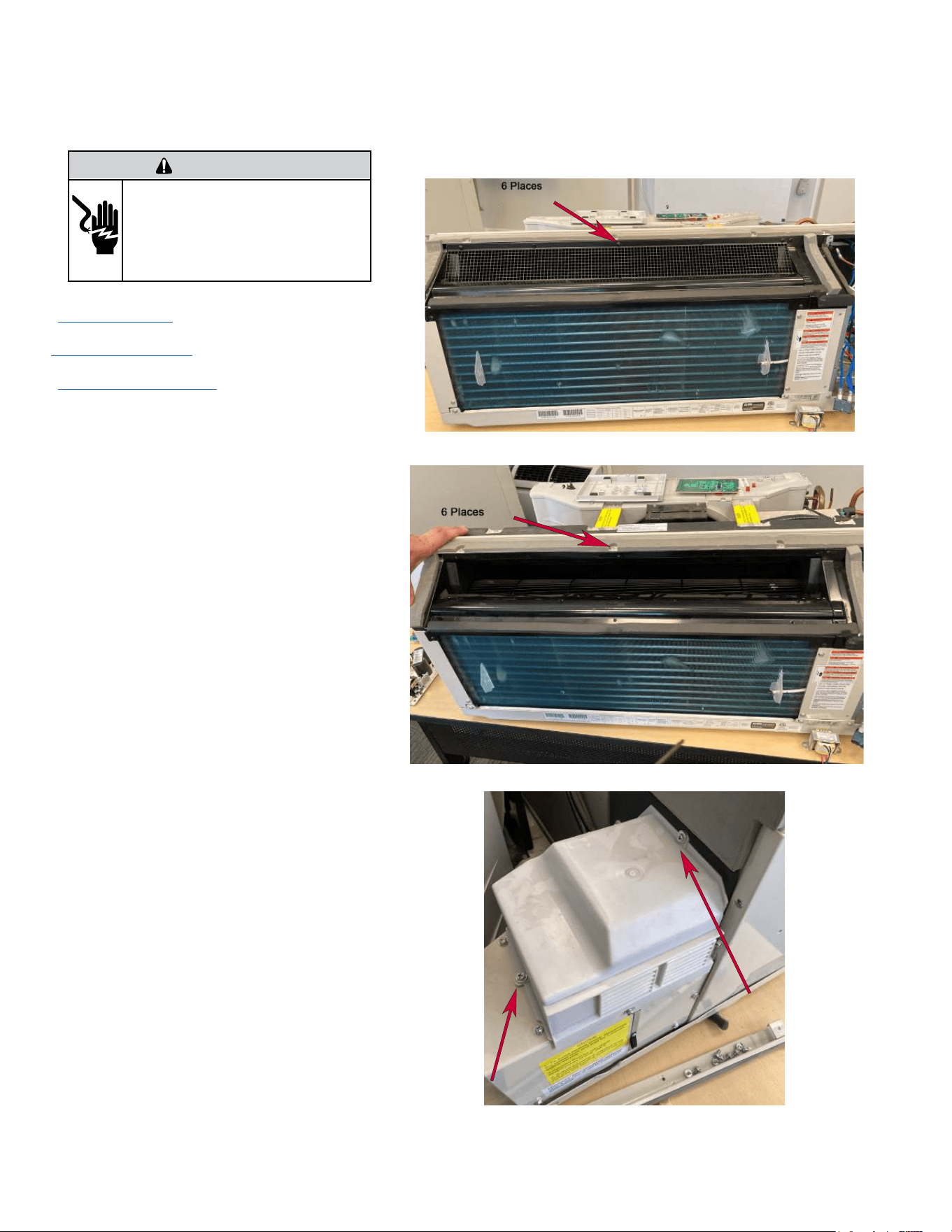
61
UNIT DISASSEMBLY AND COMPONENT REPLACEMENT
Remove Blower Wheel
WARNING
ELECTRIC SHOCK HAZARD
Turn off electric power before service or
installation. Extreme care must be used, if it
becomes necessary to work on equipment with
power applied.
Failure to do so could result in serious injury or
death.
1. Remove front panel (Figure 501).
2
. Remove User Interface (Figures 502 thru 504).
3.
Open electrical Control Box (Figure 505).
4. Remove indoor fan guard (6 screws) (Figure 514).
5. Remove top air guide (6 screws) (Figure 515).
6. Remove fresh air intake housing (2 screws) (Figure 516).
Figure 514 (Remove Indoor Fan Guard)
Figure 515 (Remove Top Guide)
Figure 516 (Remove Fresh Air Housing)
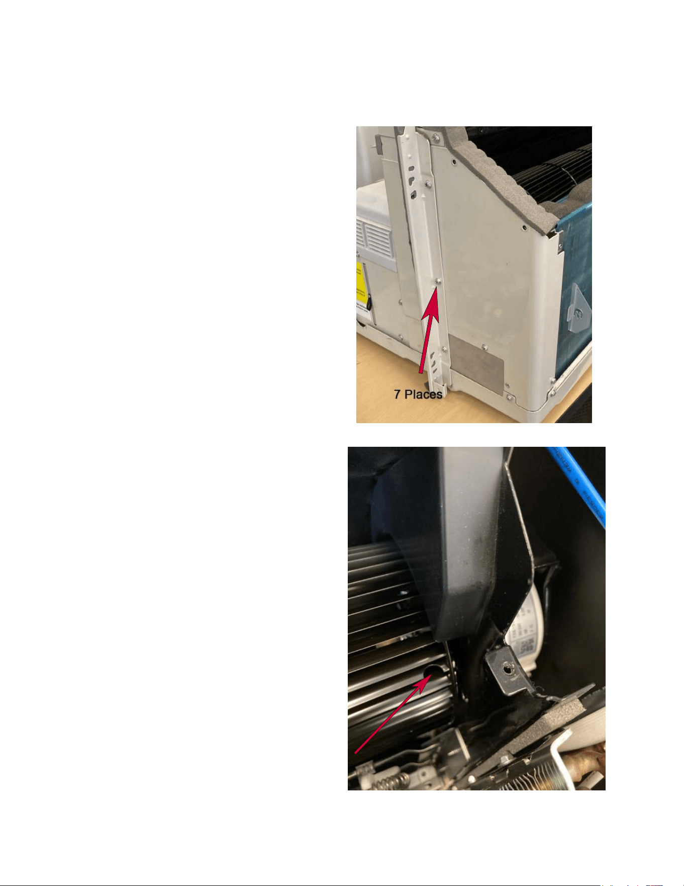
62
UNIT DISASSEMBLY AND COMPONENT REPLACEMENT
Remove Blower Wheel (Continued)
9. Remove left panel (7 screws) (Figure 517).
10. Loosen set screw (DO NOT REMOVE) from blower
motor shaft. (Figure 518).
NOTE: Set screw is a 2.5 mm “Allen Head” screw.
Figure 517 (Remove Left Panel)
Figure 518 (Blower Wheel Set Screw)
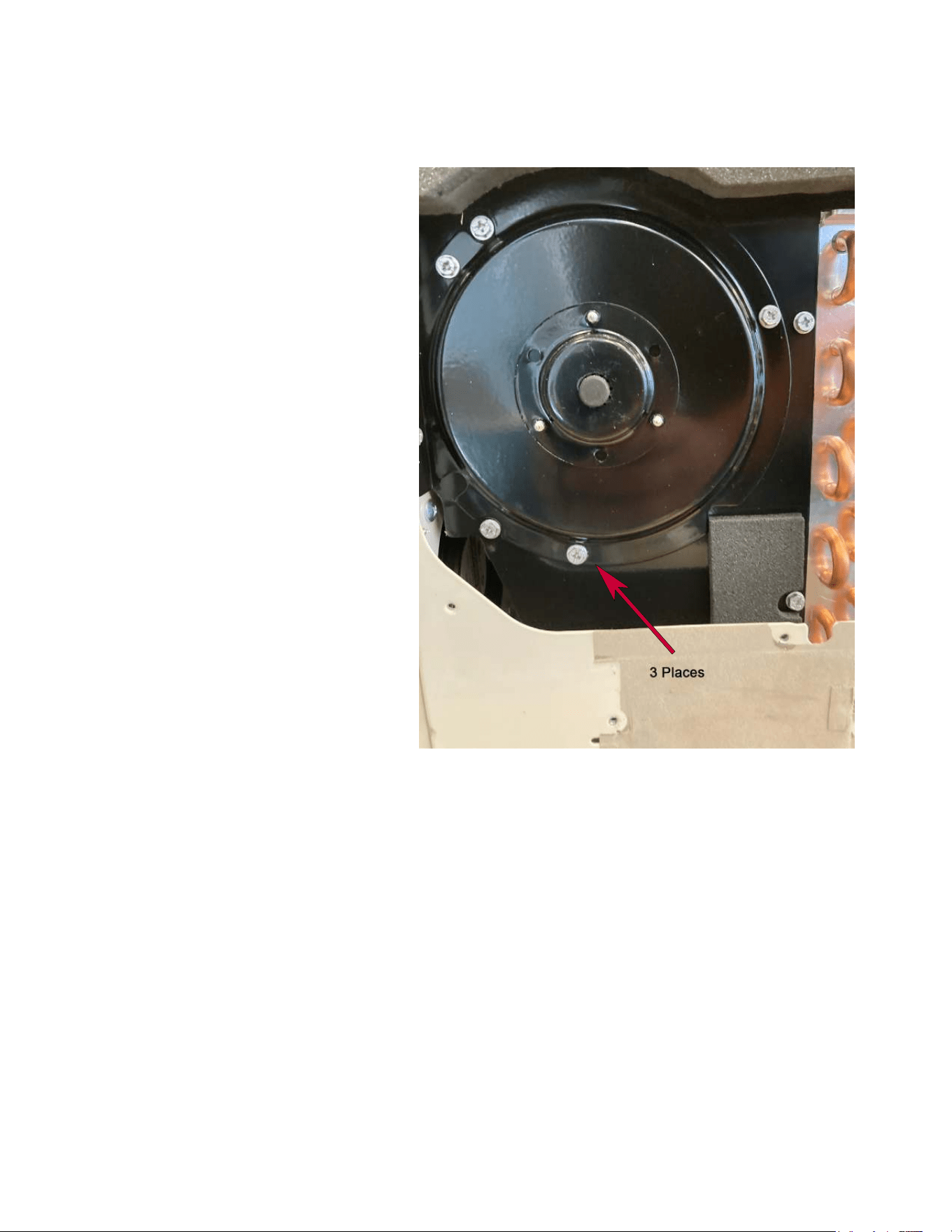
63
UNIT DISASSEMBLY AND COMPONENT REPLACEMENT
Remove Blower Wheel (Continued)
11. Remove blower end plate (3 screws)(Figure 519).
12. Slide blower assembly out of left side of unit.
Figure 519 (Blower End Plate)
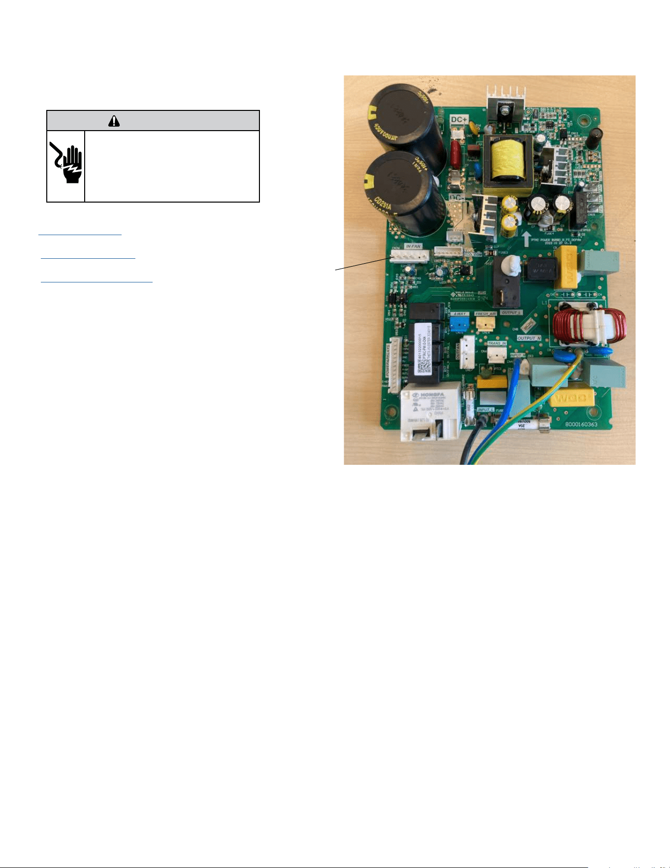
64
Figure 520 (Disconnect Indoor Blower Connector)
UNIT DISASSEMBLY AND COMPONENT REPLACEMENT
Remove Blower Wheel Motor
1. Remove front panel (Figure 501).
2. Remove User Interface (Figures 502 thru 504).
3. Open electrical Control Box (Figure 505).
4. Snip wire ties to loosen wire bundles. (Figure 521)
NOTE: It is a good practice to take pictures of the
wiring connections to facilitate reinstallation.
5. Disconnect indoor blower connector on Power PCB (Power
Board). (Figure 520).
6. Disconnect Indoor blower capacitor connector (Figure
521).
WARNING
ELECTRIC SHOCK HAZARD
Turn off electric power before service or
installation. Extreme care must be used, if it
becomes necessary to work on equipment with
power applied.
Failure to do so could result in serious injury or
death.
Indoor Fan
Motor
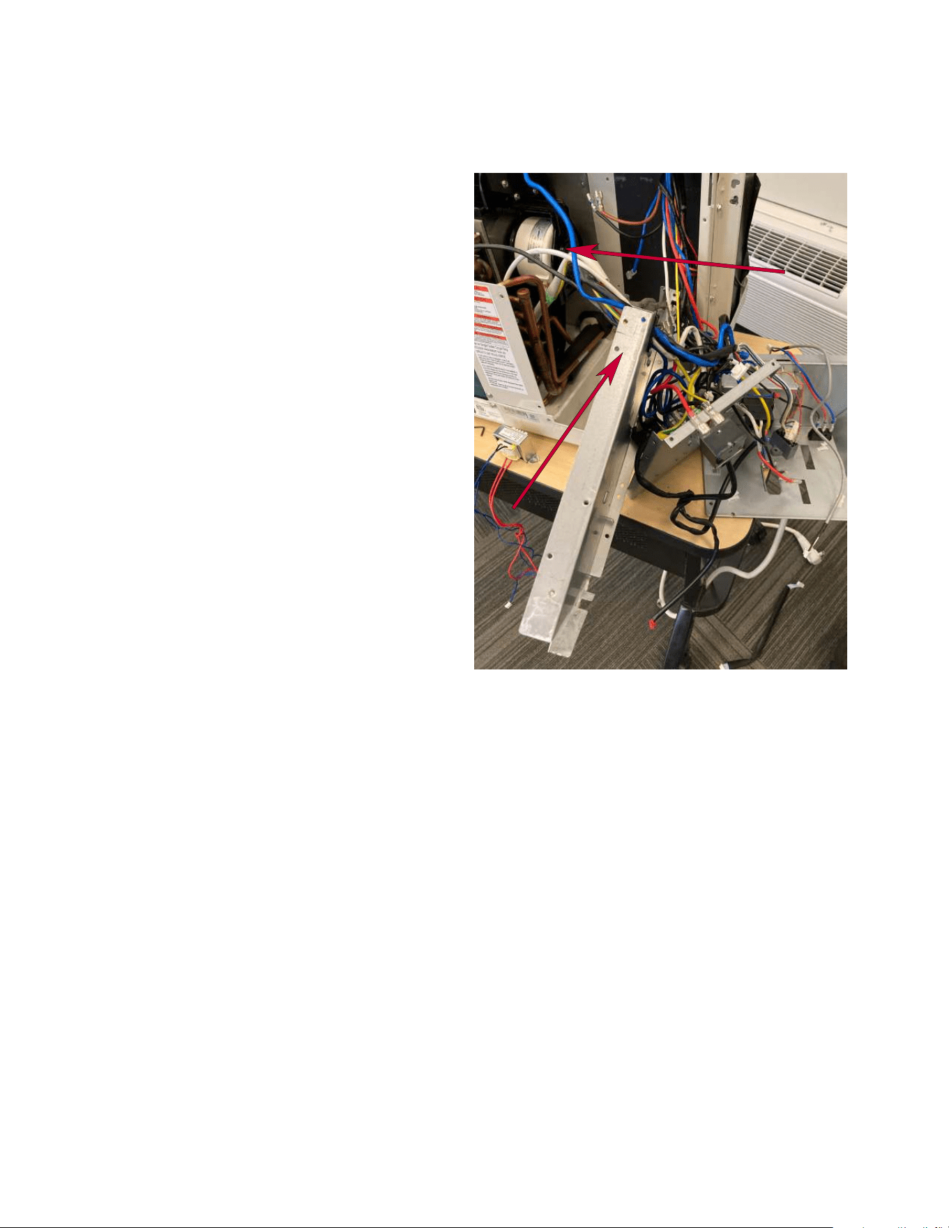
65
UNIT DISASSEMBLY AND COMPONENT REPLACEMENT
Remove Blower Wheel Motor (Continued)
Figure 522 (Remove Indoor Blower Motor Bracket)
7. Remove mounting screws from electrical box rear and
side covers and slide out of way to facilitate blower motor
replacement (Figure 522).
8. Remove fan motor bracket (3 screws).
9. Remove motor.
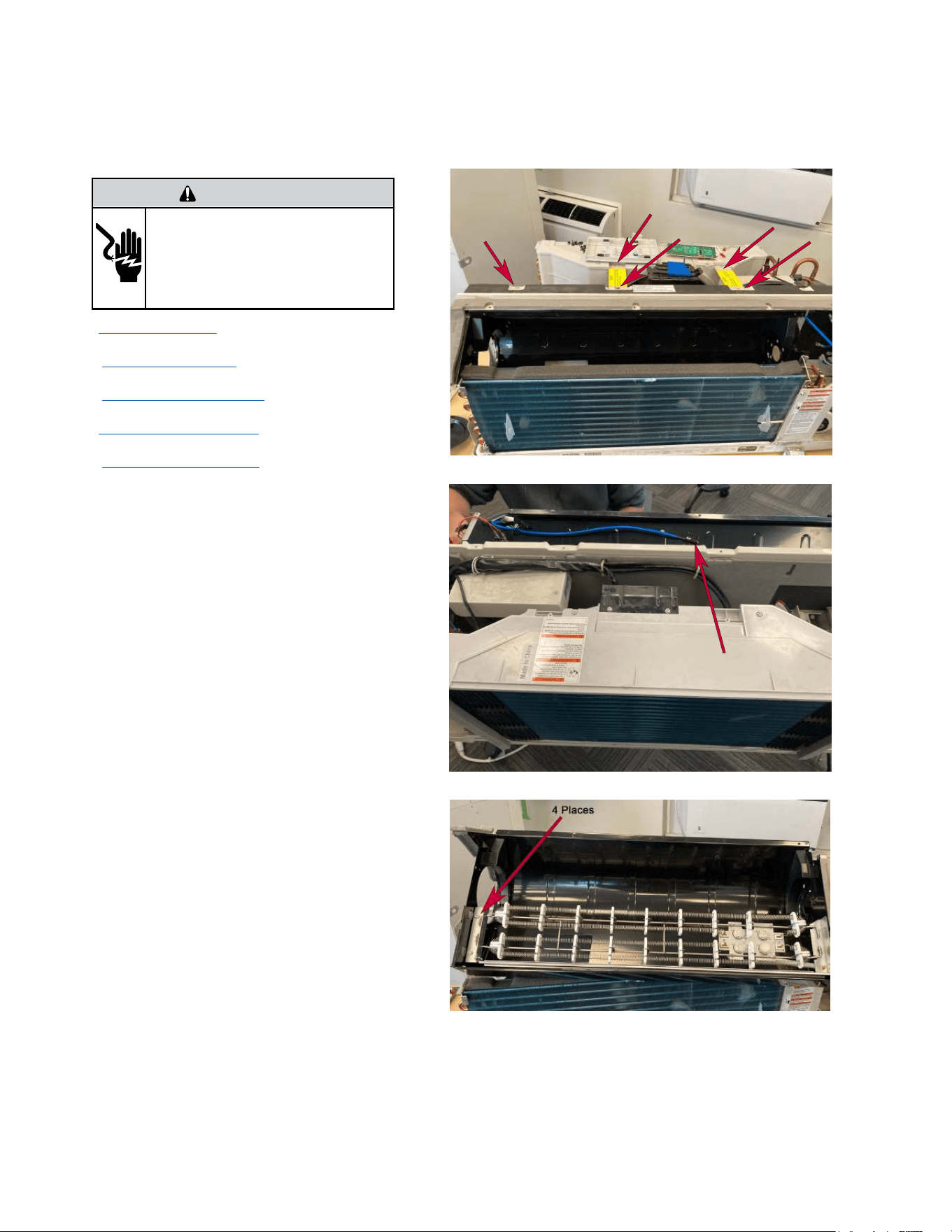
66
UNIT DISASSEMBLY AND COMPONENT REPLACEMENT
Remove Heating Element
WARNING
ELECTRIC SHOCK HAZARD
Turn off electric power before service or
installation. Extreme care must be used, if it
becomes necessary to work on equipment with
power applied.
Failure to do so could result in serious injury or
death.
1. Remove front panel (Figure 501).
2. Remove User Interface (Figures 502 thru 504).
3. Open electrical Control Box (Figure 505).
4. Remove Chassis from Wall (Figure 501)
4. Remove indoor fan blower (Figures 514 thru 519).
5. Remove top support bracket (12 screws) (Figure
523)
6. Disconnect blower housing sensor from blower
housing (Figure 524).
7. Disconnect Indoor motor capacitor wiring and
power connector at Power PCB.
8. Disconnect power leads from heater relays.
9. Disconnect heater ground wire.
10. Remove indoor blower housing (4 screws).
11. Remove heater element assembly from housing
(4 screws).
Figure 523 (Remove Top Support Bracket)
Figure 524 (Remove Blower Housing Sensor)
Figure 525 (Remove Heater Element)
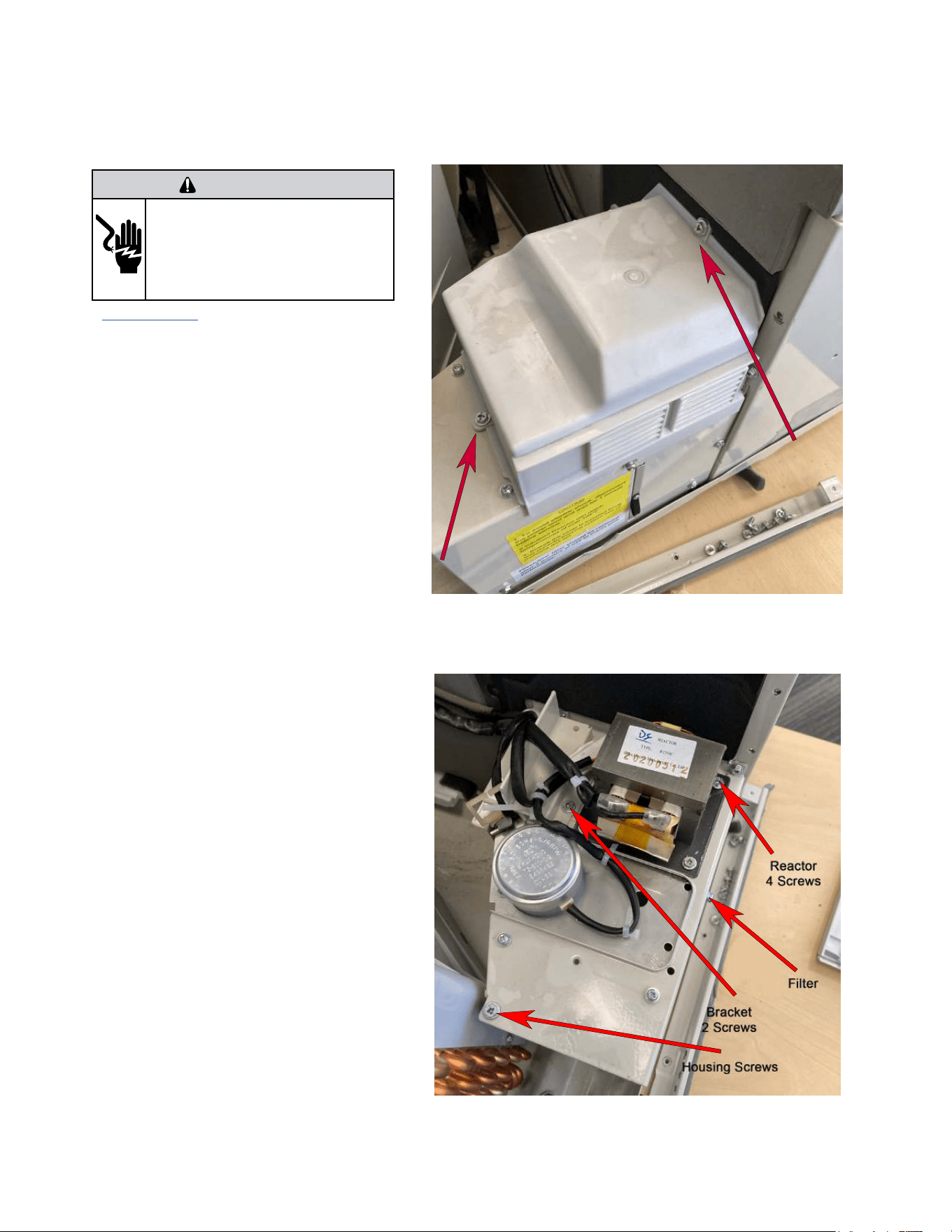
67
UNIT DISASSEMBLY AND COMPONENT REPLACEMENT
Remove Fresh air Components
WARNING
ELECTRIC SHOCK HAZARD
Turn off electric power before service or
installation. Extreme care must be used, if it
becomes necessary to work on equipment with
power applied.
Failure to do so could result in serious injury or
death.
1. Remove Chassis From wall. (Figure 501).
2. Remove Fresh air Cover (Figure 526).
3. Cut wire ties as required.
4. Remove 4 screws from reactor and unplug 2 termi-
nal wires (Figure 527).
5. Remove bracket (2 screws).
6. Remove freshair filter by sliding out.
7. Remove all screws from fresh air housing.
Figure 526 (Remove Fresh Air Housing)
Figure 527 (Remove Fresh Air brackets)
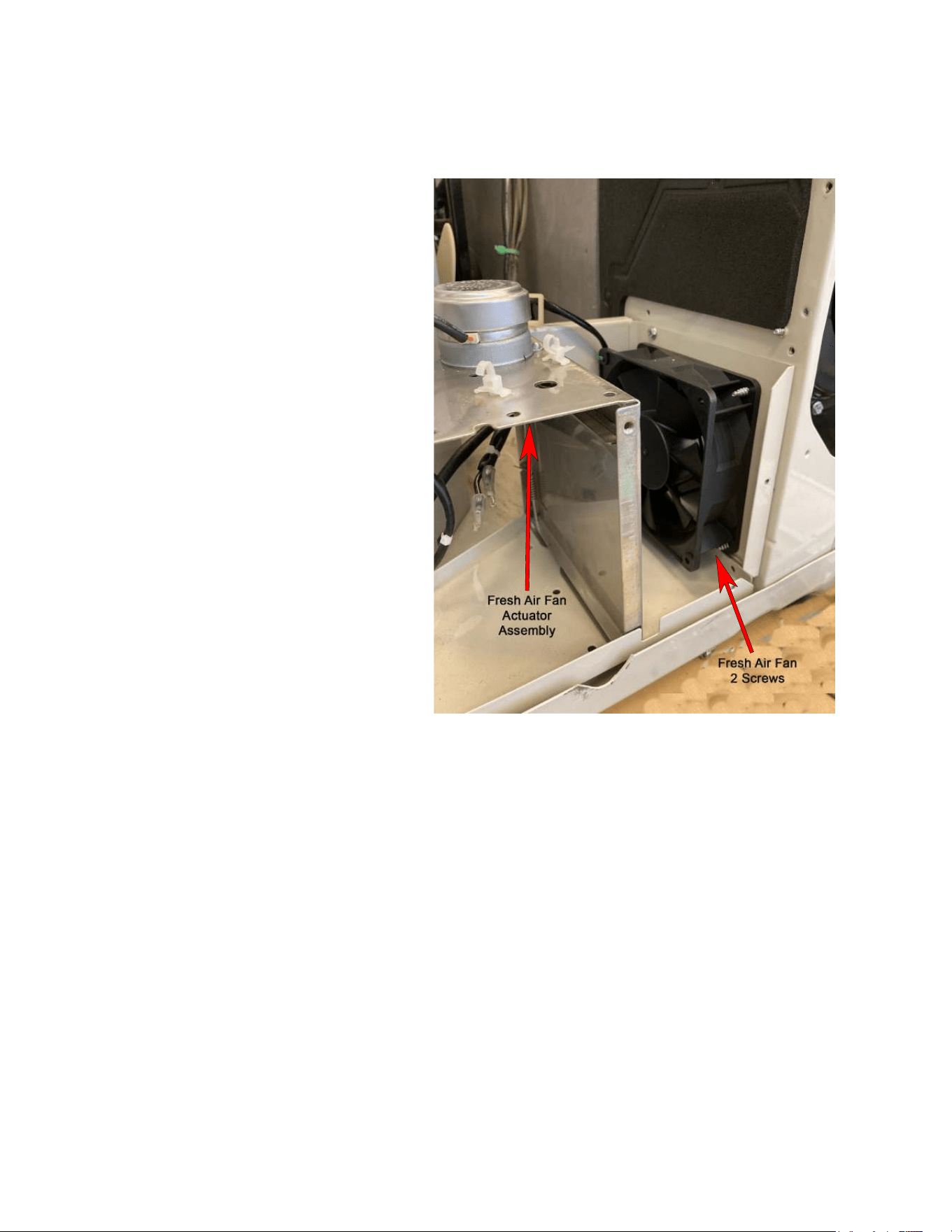
68
8) Remove fresh air actuator assembly (1 screw).
9) Remove fresh air fan assembly ( 2 screws).
UNIT DISASSEMBLY AND COMPONENT REPLACEMENT
Remove Fresh air Components (Continued)
Figure 528 (Remove Fresh Air Actuator and Fan)
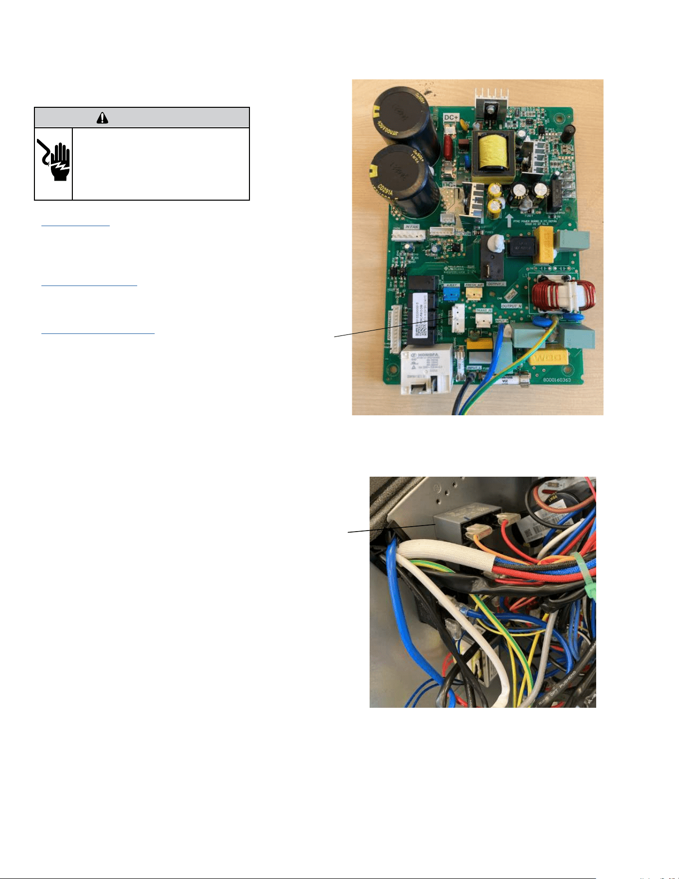
69
UNIT DISASSEMBLY AND COMPONENT REPLACEMENT
Remove Outdoor Fan
1. Remove Chassis from wall (Figure 501).
2. Remove front panel (Figure 501). (Not required for
Blade replacement)
3. Remove User Interface (Figures 502 thru 504). Not
required for Blade replacement)
4. Open electrical Control Box (Figure 505). Not
required for Blade replacement)
5. Cut wire ties as required. Not required for Blade
replacement)
6. Disconnect outdoor blower connector on
power panel. (Figure 529). Not required for Blade
replacement)
7. Disconnect Outdoor blower capacitor connector
(Figure 530). Not required for Blade replacement)
WARNING
ELECTRIC SHOCK HAZARD
Turn off electric power before service or
installation. Extreme care must be used, if it
becomes necessary to work on equipment with
power applied.
Failure to do so could result in serious injury or
death.
Figure 529 (Disconnect Outdoor Fan Connector)
Figure 530 (Disconnect Outdoor Fan Capacitor)
Outdoor
Fan
Capacitor
Outdoor
Fan
Connector
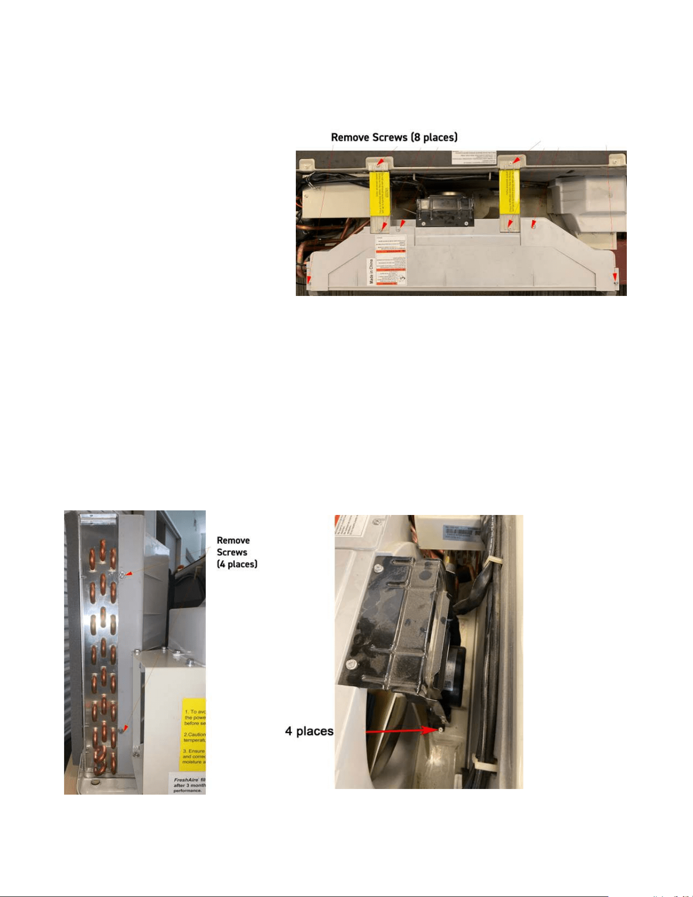
70
UNIT DISASSEMBLY AND COMPONENT REPLACEMENT
Remove Outdoor Fan (Continued)
8. Remove Brackets and Shrouds (12 screws)(Figure
531 and 532).
9. Remove Mounting screws (4 places) (Figure 533).
Figure 531 (Remove Brackets and Shroud)
Figure 532 (Remove Brackets and Shroud) Figure 533 (Remove Mounting bolts)
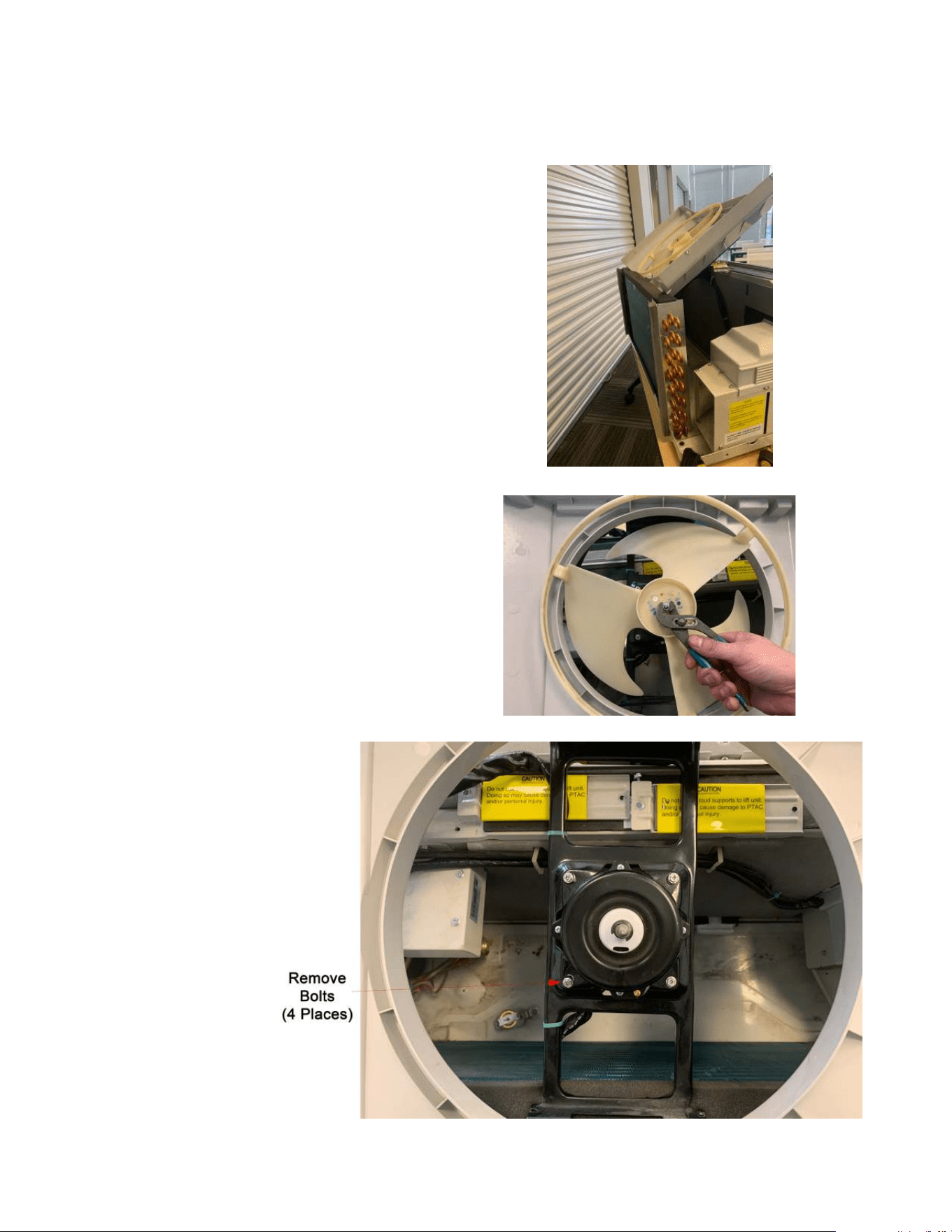
71
UNIT DISASSEMBLY AND COMPONENT REPLACEMENT
Remove Outdoor Fan (Continued)
10. Pull up and remove fan housing (Figure 534).
11. Remove shaft nut and fan blade (Figure 535).
12. Remove motor (4 places) (Figure 536).
Figure 534 (Remove Assembly)
Figure 535 (Remove fan blade)
Figure 536 (Remove Fan Motor)
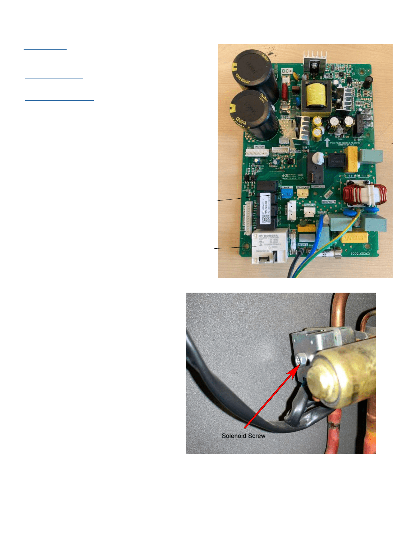
72
UNIT DISASSEMBLY AND COMPONENT REPLACEMENT
Remove Reversing valve Solenoid
1. Remove Chassis from wall (Figure 501).
2. Remove front panel (Figure 501).
3. Remove User Interface (Figures 502 thru 504).
4. Open electrical Control Box (Figure 505).
5. Cut wire ties as required.
6. Disconnect connector from Power PCB (Power Board) cn
16 and 17 and feed wire through control box housing (Figure
537).
8. Remove 1 bolt and separate solenoid from valve (Figure
539).
Figure 537 (Disconnect Solenoid Connector)
Figure 539 (Remove solenoid)
Reversing Valve
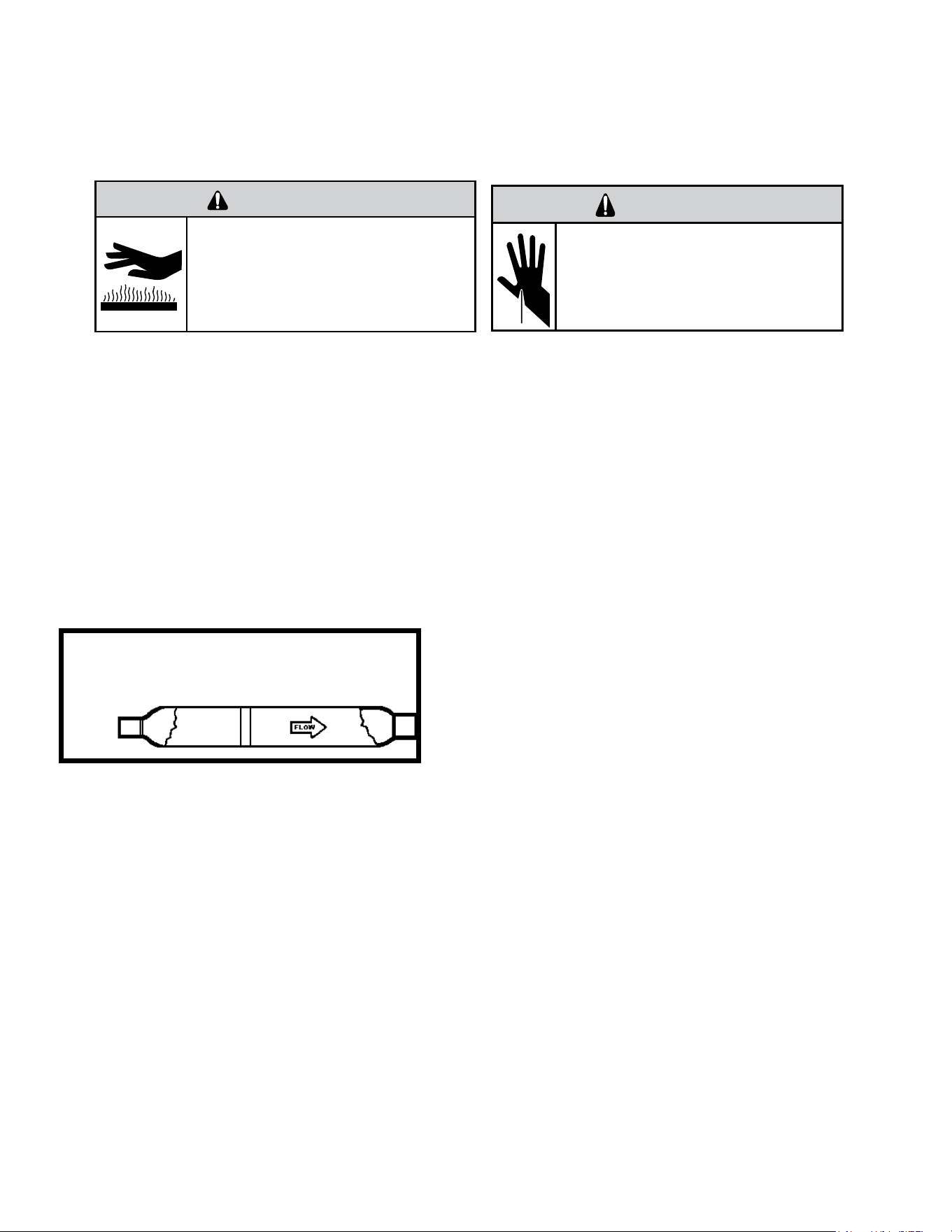
73
Metering Device - Capillary Tube Systems
All units are equipped with capillary tube metering devices. Checking for restricted capillary tubes.
1. Connect pressure gauges to unit.
2. Start the unit in the cooling mode. If after a few minutes of operation the pressures are normal, the check valve and the cooling capillary are not
restricted.
3. Switch the unit to the heating mode and observe the gauge readings after a few minutes running time. If the system pressure is lower than
normal, the heating capillary is restricted.
4. If the operating pressures are lower than normal in both the heating and cooling mode, the cooling capillary is restricted.
Check Valve
A unique two-way check valve is used on the reverse cycle heat pumps. It is pressure operated and used to direct the flow of refrigerant to the proper
capillary tube during either the heating or cooling cycle.
NOTE: The slide (check) inside the valve is made of teflon. Should it become necessary to replace the check valve, place a wet cloth around the valve
to prevent overheating during the brazing operation.
CHECK VALVE OPERATION
In the cooling mode of operation, high pressure liquid enters the check valve
forcing the slide to close the opposite port (liquid line) to the indoor coil. Refer to
refrigerant flow chart. This directs the refrigerant to the cooling capillary tube to
the indoor coil.
In the heating mode of operation, high pressure refrigerant enters the check
valve from the opposite direction, closing the port (liquid line) to the outdoor
coil. The flow path of the refrigerant is then to the heating capillary to the
outdoor coil.
Failure of the slide in the check valve to seat properly in either mode of operation
will cause flooding of the cooling coil. This is due to the refrigerant bypassing the
heating or cooling capillary tube and entering the liquid line.
COOLING MODE
In the cooling mode of operation, liquid refrigerant from condenser (liquid line)
enters the cooling check valve forcing the heating check valve shut. The liquid refrigerant is metered through cooling capillary tubes to evaporator.
(Note: liquid refrigerant will also be directed through the heating capillary tubes in a continuous loop during the cooling mode).
HEATING MODE
In the heating mode of operation, liquid refrigerant from the indoor coil enters the heating check valve forcing the cooling check valve shut. The liquid
refrigerant is metered through the heating capillary tubes to outdoor coils. (Note: liquid refrigerant will also be directed through the cooling capillary
tubes in a continuous loop during the heating mode).
COMPONENT TESTING
Hermetic Components Check
BURN HAZARD
Proper safety procedures must be followed,
and proper protective clothing must be worn
when working with a torch.
Failure to follow these procedures could
result in moderate or serious injury.
WARNING
WARNING
CUT/SEVER HAZARD
Be careful with the sharp edges and corners.
Wear protective clothing and gloves, etc.
Failure to do so could result in serious injury.
One-way Check Valve
(Heat Pump Models)
Figure 701 (Check Valve)
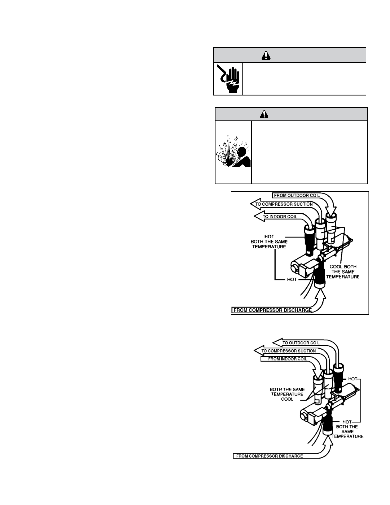
74
COMPONENT TESTING
Reversing Valve Description And Operation
A reversing valve is a component of a heat pump that changes the direction of
refrigerant flow, allowing the system to function in both heating and cooling
modes.
It consists of a pressure-operated, main valve and a pilot valve actuated by a
solenoid plunger. The solenoid is energized during the heating cycle only.
The single tube on one side of the main valve body is the high-pressure inlet to
the valve from the compressor. The center tube on the opposite side is connected
to the low pressure (suction) side of the system. The other two are connected
to the indoor and outdoor coils. Small capillary tubes connect each end of the
main valve cylinder to the “A” and “B” ports of the pilot valve. A third capillary
is a common return line from these ports to the suction tube on the main valve
body. Four-way reversing valves also have a capillary tube from the compressor
discharge tube to the pilot valve.
The plunger assembly in the main valve can only be shifted by the pressure
differential between the high and low sides of the system. The pilot section of the
valve opens and closes ports for the small capillary tubes to the main valve to
cause it to shift.
Checking the Reversing Valve
NOTE: System operating pressures must be near normal before valve can shift. NOTE: You
must have normal operating pressures before the reversing valve can shift.
Run the unit in the heating mode then disconnect one of the wires at the reversing valve
and the valve should shift to cooling mode. If valve does not shift - replace the valve(verify
the unit is properly charged before replacing valve.) For a stuck valve diagnosis run in the
cooling mode and check the temp difference between the suction line from the evaporator
and the common suction line at the compressor, if there is more than a 3 ˚F difference then
change the valve.
Checking The Reversing Valve Solenoid
The solenoid coil is an electromagnetic type coil mounted on the reversing valve and is
energized during the operation of the compressor in the heating cycle.
1. Turn off high voltage electrical power to unit.
2. Unplug line voltage lead from reversing valve coil.
3. Check for electrical resistance through the coil. If the coil is open replace the coil.
4. Check from each lead of coil to the copper liquid line as it leaves the unit or the ground
lug. There should be no continuity between either of the coil leads and ground; if there is,
coil is grounded and must be replaced.
5. If coil tests okay, reconnect the electrical leads.
6. Make sure coil has been assembled correctly.
NOTE: Do not start unit with solenoid coil removed from valve, or do not remove coil after
unit is in operation. This will cause the coil to burn out.
Figure 702 (Reversing Valve in Heating Mode)
WARNING
ELECTRIC SHOCK HAZARD
Disconnect power to the unit before
servicing. Failure to follow this warning
could result in serious injury or death.
WARNING
HIGH PRESSURE HAZARD
Sealed Refrigeration System contains refrigerant
and oil under high pressure.
Proper safety procedures must be followed,
and proper protective clothing must be worn
when working with refrigerants.
Failure to follow these procedures could
result in serious injury or death.
Figure 703 (Reversing Valve in cooling mode)
75
COMPONENT TESTING
Compressor Checks
Overloads
The compressor is equipped with either an external or internal overload which senses both motor amperage and winding temperature. High motor
temperature or amperage heats the overload causing it to open, breaking the common circuit within the compressor. Heat generated within the
compressor shell, usually due to recycling of the motor, is slow to dissipate. It may take anywhere from a few minutes to several hours for the
overload to reset.
Checking the Overloads
External Overloads
With power off, remove the leads from compressor terminals. If the compressor is hot, allow the overload to cool before starting check. Using an
ohmmeter, test continuity across the terminals of the external overload. If you do not have continuity; this indicates that the overload is open and must
be replaced.
Internal Overloads
The overload is embedded in the motor windings to sense the winding temperature and/or current draw. The overload is connected in series with the
common motor terminal.
Should the internal temperature and/or current draw become excessive, the contacts in the overload will open, turning off the compressor. The
overload will automatically reset, but may require several hours before the heat is dissipated.
Checking the Internal Overload
1. With no power to unit, remove the leads from the compressor terminals.
2. Using an ohmmeter, test continuity between terminals C-S and C-R. If no continuity, the compressor overload is open and the compressor must be
replaced.
WARNING
ELECTRIC SHOCK HAZARD
Turn off electric power before service or
installation.
All electrical connections and wiring MUST be
the National Electrical Code and all local codes
which have jurisdiction.
Failure to do so can result in personal injury or
death.
BURN HAZARD
Proper safety procedures must be followed,
and proper protective clothing must be worn
when working with a torch.
Failure to follow these procedures could
result in moderate or serious injury.
WARNING
Return to Error Codes and Solutons
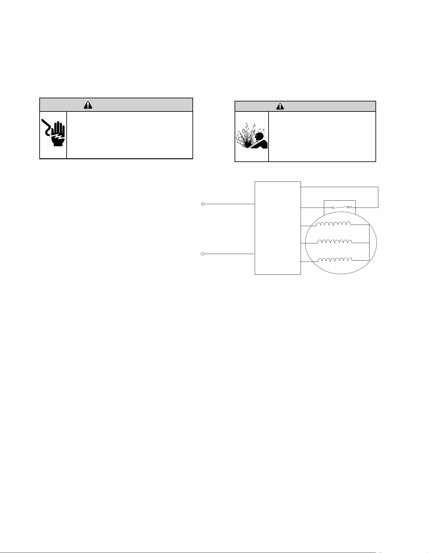
76
WARNING
ELECTRIC SHOCK HAZARD
Turn off electric power before service or
installation. Extreme care must be used, if it
becomes necessary to work on equipment with
power applied.
Failure to do so could result in serious injury or
death.
WARNING
HIGH PRESSURE HAZARD
Sealed Refrigeration System contains refrigerant
and oil under high pressure.
Proper safety procedures must be followed,
and proper protective clothing must be worn
when working with refrigerants.
Failure to follow these procedures could
result in serious injury or death.
Figure 705 (Compressor Windings)
COMPONENT TESTING
Compressor Checks
DC
INVERTER
&
R U( )
S V( )
CONTR OLLER
T W( )
POWER
OVERLOAD PROT ECTION
Gain access to compressor and IPM PCB (Inverter Board) by
removing chassis from wall.
1) Disconnect terminals R(U), S(V), and T(W) from the
compressor.
Resistance Test.
2) Set Ohm meter to the lowest scale and check continuity
between pins R(U), S(V), and T(W).
At room temperature (70°- 95°F) the resistance should
be approximately 2.2 ohms. The Ohm values will change
significantly at different temperatures. This does not indicate
that the compressor windings are faulty. A reading of open
(infinity), or a significant difference in the resistance between
the windings does indicate that the compressor windings are
faulty.
3) Check for continuity from between pins R(U) to ground,
S(V) to ground, and T(U) to ground)
The compressor windings are faulty if the there is continuity
from the compressor windings to ground.
4) Common signs compressor is faulty:
• Compressor motor lock.
• Discharge pressure value approaches static pressure
value .
• Compressor motor winding abnormality.
Note:
• Don’t put a compressor on its side or turn over.
• Assemble the compressor quickly after removing the
plugs. Prolonged exposure will damage the internal
components of the compressor
• Ensure wiring is correct before operating. Reverse op-
eration will permanently damage the compressor.
• Electric Reactor
Common Problems:
• Sound abnormality
• Runs in a sporadic rhythm.
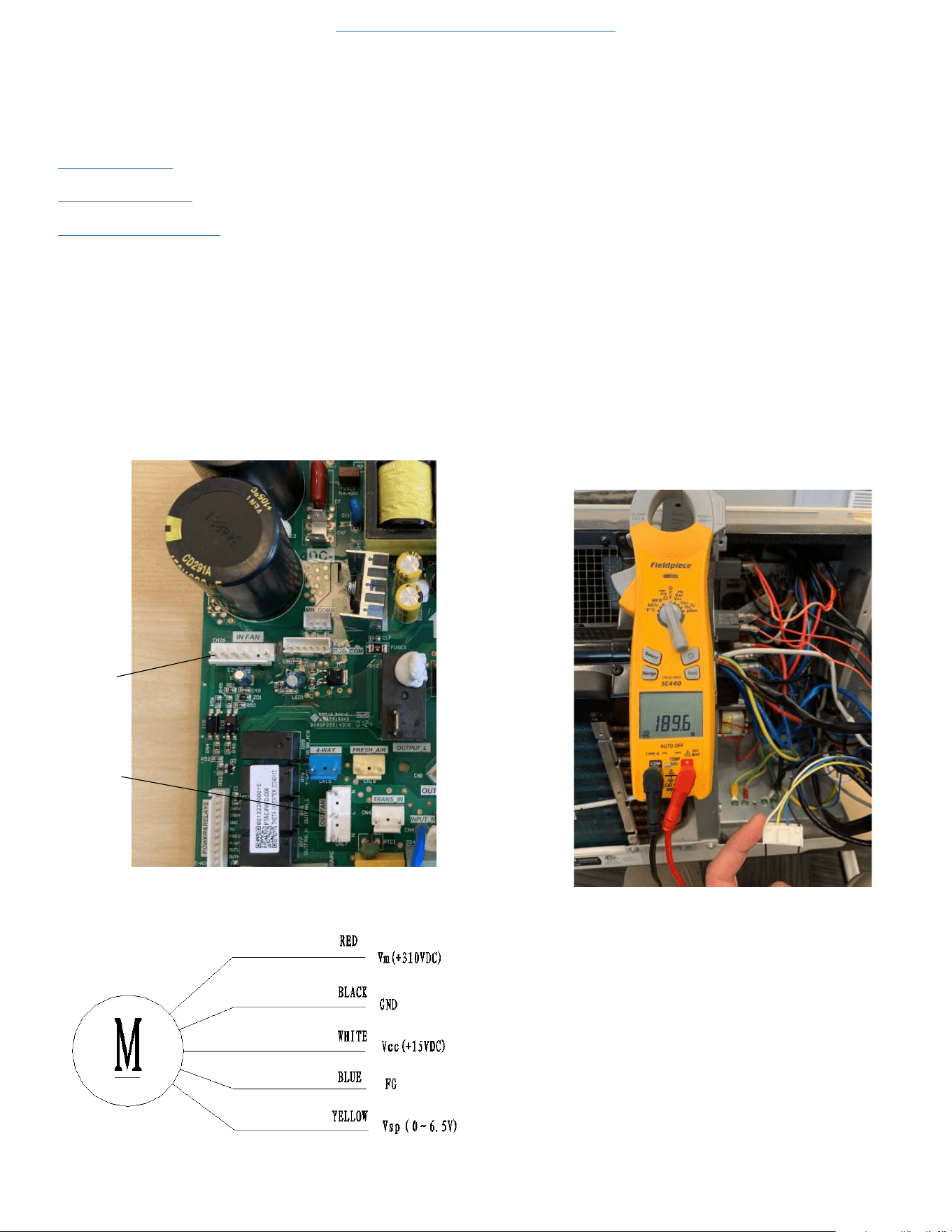
77
COMPONENT TESTING
Check Indoor and Outdoor Fan Motors
Gain Access to the Power PCB (Power Board).
1. Remove power from the unit.
2.
Remove front panel (Figure 501).
3. Remove User Interface (Figures 502 thru 504).
4. Open electrical Control Box (Figure 505).
5. Test Indoor Fan Motor
a. On Power PCB, disconnect Indoor fan connector. (See figure
706.1)
b. Resistance Test.
Test the resistance of the main winding. The indoor fan motor is
faulted if the resistance of main winding is 0 (short circuit)or ∞
open circuit.
c. DC Voltage test
Manually rotate indoor fan motor slowly for several revolutions,
and measure voltage “YELLOW” and “GND” on motor. The volt-
age repeats 0V DC and 5V DC.
Figure 706.1
Figure 706.2
6. Test Outdoor Fan motor.
a. Restore power to unit.
b. Place unit in cooling mode and ensure demand for cooling.
The outdoor fan has two speeds, low and high. When T4 is above
80°F, the fan operates in high speed.
When T4 drops to 77°F the fan operates in low speed.
c . Check voltage between Neutral and High, or low.
Line voltage (200-300 VAC) should be present.
If no voltage is present check cable and resistance values on
motor.
d. Remove power from the unit
e. Disconnect Outdoor fan motor connector from Power PCB. See
figure 706.1
f. Check for continuity between pins on fan plug connector.
N-H = 189.6 ohms +-10%
N-M = 216.2 ohms+-10%
N-L = 240.6 ohms +-10%
Figure 707
Return to Error Codes and Solutons
Indoor DC Fan Motor
Outdoor DC Fan Motor
Indoor Fan
Motor
Outdoor Fan
Motor
78
COMPONENT TESTING
Check Outdoor Fan Motor Capacitor
Gain Access to the Power PCB (Power Board).
1. Remove front panel (Figure 501).
2. Remove User Interface (Figures 502 thru 504).
3. Open electrical Control Box (Figure 505).
WARNING
RISK OF ELECTRIC SHOCK
Unplug and/or disconnect all electrical power
to the unit before performing inspections,
maintenances or service.
Failure to do so could result in electric shock,
serious injury or death.
NOTE: Many motor capacitors are internally fused. Shorting the terminals will blow the fuse, ruining the capacitor. A 20,000 ohm 2 watt resistor can
be used to discharge capacitors safely. Remove wires from capacitor and place resistor across terminals.
1. Disconnect leads to capacitor that you are checking.
2. Bleed down capacitor with 2 watt resistor.
3. Set multi-meter to diode check setting.
4. Check Resistance across capacitor terminals by placing the red lead on the run terminal and the black lead on the common terminal. (The meter will
send a small charge into the capacitor)
5. The meter should show a certain amount of resistance initially and then increase in resistance as the charge in the capacitor dissipates until infinity
is reached.
6. If the meter shows continuity, or does not bleed back down to infinity, the capacitor is shorted and should be replaced.
7. If the meter initially shows infinity the capacitor is open and should be replaced.
Check Capacitance values in micro Farads using capacitor analyzer.
1. Indoor fan capacitor should read 1.5 uf.
2. Outdoor fan capacitor should read 3.0 uf.
Return to Error Codes and Solutons
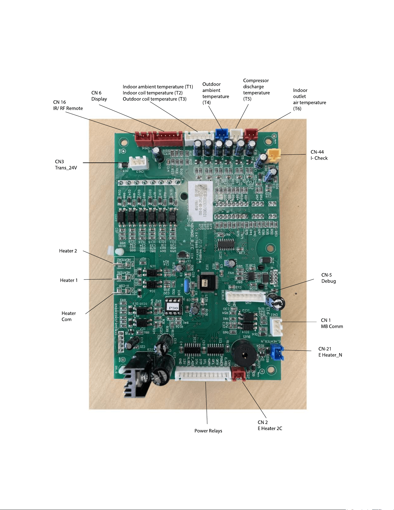
79
COMPONENT TESTING
Main PCB (logic) Board Connector Identification
Figure 709 (Main PCB (logic) Board)
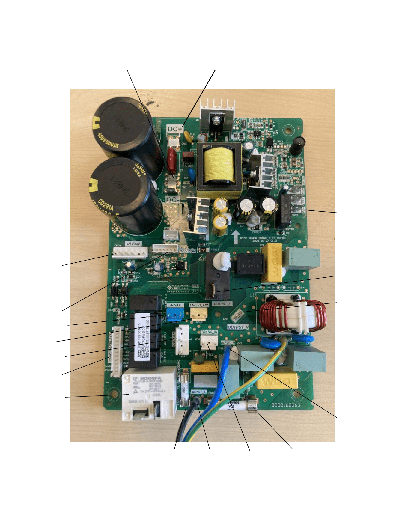
80
COMPONENT TESTING
Power PCB (Power Board) Connector Identification
Figure 710 (Power PCB (Power Board)
Return to Error Codes and Solutons
DC Bus Lines (positive)DC Bus Lines (negative))
MB Com
Mod Com
Indoor Fan
Motor
Power Relays
Electric
Heater
Relay
Reversing Valve
Fresh Air
Fan Door Motor
Fuse
Fuse
Transformer
Fresh Air Fan +
Fresh Air Fan Low
Fresh Air Fan High
L (L1) Output
N (L2) Output
N (L2) Input
L (L1) Input
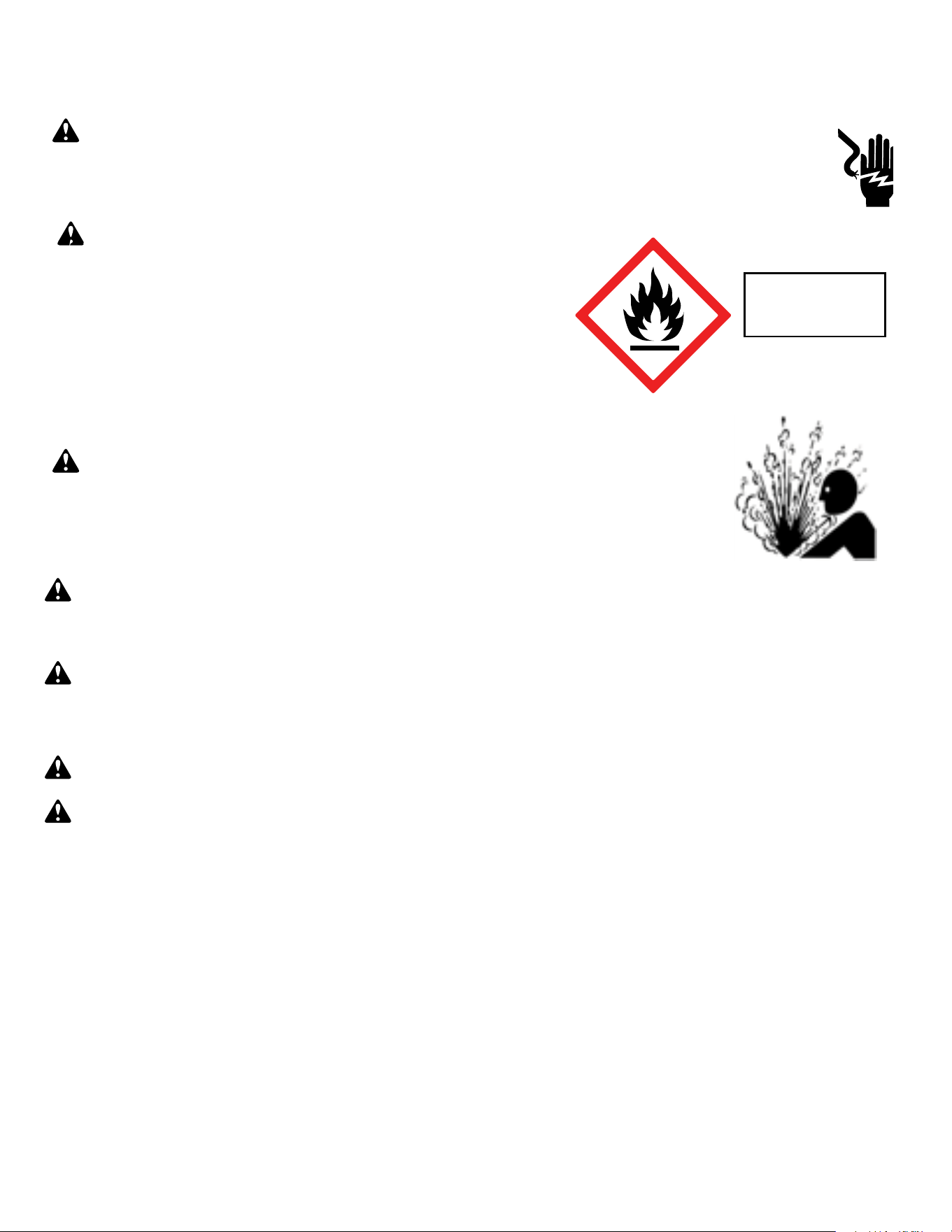
81
Warning: Prior to beginning work on systems containing FLAMMABLE REFRIGERANTS, safety checks are necessary to ensure that the risk of
ignition is minimized.
NOTICE: Individuals working on these units must be EPA 608 Certified along with A2L Refrigerant Training.
Warning: Refrigerant 32 cannot be used as a retrofit for R-410A refrigerant. The mixing of refrigerant across classes is prohibited. R-32 Is not a
drop in replacement for R-410A.
General Work Area: All maintenance staff and others working in the installation area shall be instructed on the nature of work being carried out. Work in
confined spaces as defined by the Occupational Safety And Health Administration shall be avoided.
Warning: Job site should be examined for safety hazards such as flammable vapors, ignition sources, ventilation and confined spaces. Create a
safe perimeter with barriers and signs designating a flammable area.
Warning: Work shall be undertaken under a controlled procedure so as to minimise the risk of a flammable gas or vapor being present while
the work is being performed.
Check for presence of refrigerant:
• The area shall be checked with an appropriate refrigerant detector prior to and during work, to ensure the technician is aware of potentially toxic
or flammable atmospheres.
• Ensure that the leak detection equipment being used is suitable for use with all applicable refrigerants, i.e. non-sparking, adequately sealed or
intrinsically safe.
• Under no circumstances shall potential sources of ignition be used in the searching for or detection of refrigerant leaks. A halide torch (or any other
detector using a naked flame) shall not be used.
• The following leak detection methods are deemed acceptable for all refrigerant systems:
1. Electronic leak detectors may be used to detect refrigerant leaks but, in the case of FLAMMABLE REFRIGERANTS, the sensitivity may not
be adequate, or may need re-calibration. (Detection equipment shall be calibrated in a refrigerant-free area.) Ensure that the detector is not a
potential source of ignition and is suitable for the refrigerant used. 2. Leak detection fluids are also suitable for use with most refrigerants but the
use of detergents containing chlorine shall be avoided as the chlorine may react with the refrigerant and corrode the copper pipe-work.
If a leak is suspected, all flame sources shall be removed/extinguished.
If a leakage of refrigerant is found which requires brazing, all of the refrigerant shall be recovered from the system per EPA guidelines.
Presence of fire extinguisher: If any hot work is to be conducted on the refrigerating equipment or any associated parts, a class ABC Rated fire extinguishing
equipment shall be available to hand. Have a class ABC Rated fire extinguisher adjacent to the charging area.
WARNING: Electrical Shock Hazard
Disconnect all power to the unit before starting maintenance. All electrical connections and wiring MUST be installed by a qualified
electrician and conform to all codes which have jurisdiction. Failure to do so can result in property damage, severe electrical
shock or death.
WARNING: This Product uses R-454B Refrigerant
Do not use means to accelerate the defrosting process or to clean, other than those
recommended by the manufacturer.
When not installed, the appliance shall be stored in a room without continuously
operating ignition sources (for example: open flames, an operating gas appliance or
an operating electric heater.
Do not pierce or burn.
Be aware that refrigerants may not contain an odor.
WARNING:
Refrigeration System under High pressure
Do not puncture, heat, expose to flame or incinerate. Only certified refrigeration technicians should service this
equipment. R454B systems operate at higher pressures than R22 equipment. Appropriate safe service and
handling practices must be used.
Refrigerant
Safety Group
A2L
R-32 SEALED SYSTEM REPAIR
General Information

82
Warning:
No ignition sources: No person carrying out work in relation to a REFRIGERATING SYSTEM which involves exposing any pipe work shall use any sources
of ignition in such a manner that it may lead to the risk of fire or explosion. All possible ignition sources, including cigarette smoking, should be kept
sufficiently far away from the site of installation, repairing, removing and disposal, during which refrigerant can possibly be released to the surrounding
space. Prior to work taking place, the area around the equipment is to be surveyed to make sure that there are no flammable hazards or ignition risks.
Ventilated Area: Ensure that the area is in the open or that it is adequately ventilated before accessing the refrigerant in the system or conducting any hot
work. A degree of ventilation shall continue during the period that the work is carried out. The ventilation should safely disperse any released refrigerant
away from the work area or external to building envelope.
During Repairs To Sealed Components: All power must be removed from the equipment being worked on prior to any removal of sealed covers, etc. If
it is absolutely necessary to have an electrical supply to equipment during servicing, then a constant leak detector shall be located at the most critical
point to warn of a potentially hazardous situation.
Checks And Repairs To Electrical Devices:
• Repair and maintenance to electrical components shall include initial safety checks and component inspection procedures. If a fault exists that could
compromise safety, then no electrical supply shall be connected to the circuit until it is satisfactorily dealt with. If the fault cannot be corrected
remove power supply to unit. DO NOT OPERATE.
• Initial safety checks shall include:
•That capacitors are discharged: this shall be done in a safe manner to avoid possibility of sparking;
•That no live electrical components and wiring are exposed while charging, recovering or purging the system;
•Verify unit is properly grounded.
• Particular attention shall be paid to the following to ensure that by working on electrical components, the casing is not altered in such a way that the
level of protection is affected. This shall include damage to cables, excessive number of connections, terminals not made to original specification,
damage to seals, incorrect fitting of glands, etc.
• Ensure that the apparatus is mounted securely.
• Ensure that seals or sealing materials have not degraded to the point that they no longer serve the purpose of preventing the ingress of flammable
atmospheres. Replacement parts shall be in accordance with the manufacturer’s specifications.
•
The following is a list of important considerations when working with R-32 equipment:
• R-32 pressure is similar to R-410A and approximately 60% higher than R-22 pressure.
• R-32 cylinders must not be allowed to exceed 125˚F, they may leak or rupture.
• R-32 must never be pressurized with a mixture of compressed air, it may become MORE flammable.
• Servicing equipment and components must be specifically designed for use with R-32 and dedicated to prevent contamination.
• Manifold sets must be equipped with gauges capable of reading 750 psig (high side) and 200 psig (low side), with a 500-psig low-side retard.
• Gauge hoses must have a minimum 750-psig service pressure rating.
• Recovery cylinders must have a minimum service pressure rating of 400 psig, (DOT 4BA400 and DOT BW400 approved cylinders).
• POE (Polyol-Ester) lubricants must be used with R-32 equipment.
• To prevent moisture absorption and lubricant contamination, do not leave the refrigeration system open to the atmosphere for extended periods
of time.
• If unit refrigerant is low, recover the refrigerant, evacuate, and recharge unit to nameplate amount.
• If there is any amount of refrigerant in the system charge from the low side.
• Always charge by liquid inverted.
NOTE: Sealed system repairs to cool-only models require the installation of a liquid line drier.
NOTE: Sealed system repairs to models with a heat pump require the installation of a suction side drier.
Verify with tool manufacturers that all tools used during this repair are non-sparking and can be used with A2L Refrigerants.
No halide torches for leak testing.
Refrigerant monitors or detectors must be used to detect refrigerant in the work area.
• R-32 A2L Refrigerant Recovery System.
• Vacuum Pump rated for A2L refrigerant (capable of 300 microns or less vacuum.)
• Nitrogen bottle with purging and pressurizing capabilities up to 550 psi.
• Oxy/ Acetylene torch or similar equipment utilized for brazing.
• Non-Sparking (Not Halide)Electronic Leak Detector rated for detecting A2L refrigerant.
• Digital refrigerant scale
R-32 SEALED SYSTEM REPAIR
General Information
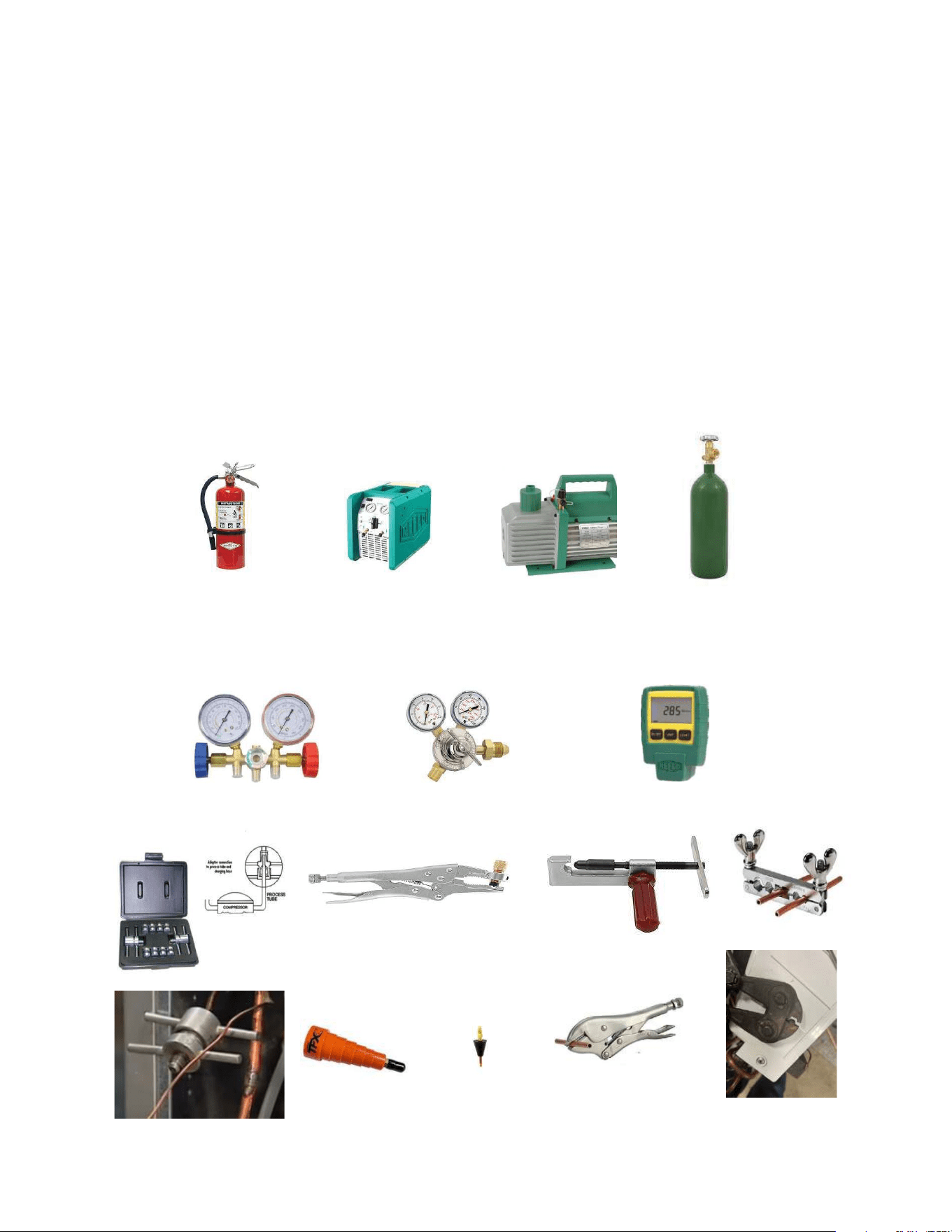
83
• Refrigeration Gauges rated for A2L Refrigerants with temp scales for R-32 refrigerant.
• Gauge Manifold (Right handed threads).
• A2L compatible Vacuum Gauge capable of 300 microns or less.
• Nitrogen regulator for purging and testing, rated to 800 psi. (Capable of low psi flow)
• Pipe tubing cutter.
• Refrigerant recovery cylinder. (Flammable A2L label)
• Ventilation fan.
• Class ABC fire extinguisher.
• Process Tube adapter kit
• Recovery access tool.
• Purge hose fittings
• Pinch off and opening tools
R-32 SEALED SYSTEM REPAIR
Required Equipment
Process tube adapter kit
Pinch off and opening tools
Recovery access tool
Purge hose fittings
Recovery Machine
Vaccum Pump
Nitrogen
ABC Fire Extinguisher
Guage Manifold
Nitrogen Regulator
Vaccum Guage

84
R-32 SEALED SYSTEM REPAIR
Refrigerant Removal, Recovery, and Evacuation
NOTE: When accessing the refrigerant in the system to make repairs or for any other purpose, conventional procedures shall be used. However, for
FLAMMABLE REFRIGERANTS (R-32 is classified in the A2L group for mildly flammable refrigerants) it is important that best practice is followed since
flammability is a consideration. Follow all EPA 608 regulations and procedures along with AHRI 15 Best Practices for A2L refrigerants.
Warning: Ensure sufficient ventilation at the repair place.
Warning: Ensure there are no open flame sources or hot surfaces that exceed 1200˚F in the work area.
Warning: Discharge capacitors in a way that won’t cause any spark. The standard procedure to short circuit the capacitor terminals usually
creates sparks.
NOTICE: Ensure that the following precautions are taken prior to opening the sealed system.
• Verify Recovery machine is rated for A2L refrigerants.
• Mark the Job site inspection area as flammable work zone using appropriate signs.
• Utilize a Refrigerant leak detector or refrigerant monitor to sense the area for the presence of refrigerants.
• Disconnect all power supply to unit.
• Properly ground all equipment and hoses along with tank to prevent a static build up .
• Ensure adequate ventilation is provided for the job site.
• Do not mix A2L refrigerant Gages and hoses with other refrigerants.
• Keep exposure of refrigerant to Air to as minimum as possible (creates a dangerous condition).
• Under no circumstances is the mixing of refrigerants in the recovery cylinders allowed and should be strictly avoided at all times. Do not
introduce oxygen into any recovery cylinders.
1. Install a piercing valve to recover refrigerant from the sealed system. (Piercing valve must be removed from the system before recharging.)
2. Recover refrigerant to EPA sec. 608 standards. If a low charge is suspected weigh recovered refrigerant and compare to unit nameplate.
NOTE: DO NOT RECOVER TO A VACUUM PRIOR TO FLUSHING WITH NITROGEN. STOP RECOVERY AT 0-5 PSI.
3. Flush refrigerant out of system with a dry nitrogen purge, make sure you energize and de-energize all reversing valves and solenoid valves to release
any trapped refrigerant.(3-5minutes).
4. Perform an evacuation to 29.9 in. hg. and break vacuum with Dry Nitrogen.
5. Re-purge the unit for 3-5 mins or until the nitrogen flows out both process tubes.
6. Re-evacuate unit to 29.9 in. hg. and break vacuum with Dry Nitrogen.
8. Open the refrigerant circuit by cutting out components.
9. Cut off the crimp on the process tubes and install a 5/16 copper access fitting to the process tube.
Transportation
Be aware that local, state, and national codes exist that regulate the transportation of flammable gases. Be sure to become informed of the regulations and always stay
compliant.
85
R-32 SEALED SYSTEM REPAIR
Component Replacement/Brazing
• Warning: Ensure sufficient ventilation at the repair place.
Warning: Presence of fire extinguisher. If any hot work is to be conducted on the refrigerating equipment or any associated parts, have a ABC
class fire extinguisher available to hand.
Warning: No person carrying out work in relation to a REFRIGERATING SYSTEM which involves exposing any pipe work shall use any sources of ignition in
such a manner that it may lead to the risk of fire or explosion. All possible ignition sources, including cigarette smoking, should be kept sufficiently far away from the site
of installation, repairing, removing and disposal, during which refrigerant can possibly be released to the surrounding space. Prior to work taking place, the area
around the equipment is to be surveyed to make sure that there are no flammable hazards or ignition risks.
Warning: Ensure there are no open flame sources or hot surfaces that exceed 1200˚F in the work area.
NOTE: When brazing is required, the following procedures shall be carried out in the right order:
1. Remove and recover refrigerant, and evacuate the system. Refer to the refrigerant removal, recovery, and evacuation section of this manual.
Warning: Under no circumstances shall potential sources of ignition be used in the searching for or detection of refrigerant leaks. A halide torch (or any other
detector using a naked flame) shall not be used.
2. Perform a check of the work area for the presence of flammable refrigerant prior to brazing or performing any hot work. Use a non-Sparking (Not
Halide ) A2L certified Electronic Leak Detector rated for detecting R-32 refrigerant.
3. Re-pipe all repairs and install all components to sealed system.
4. Purge nitrogen through the unit. at approximately 2-3 psi through the duration of the brazing process. (Nitrogen must be purging through the unit while
any brazing is being performed.)
5. Pressure test unit to 550 psi minimum and hold pressure for 30 minutes minimum. Inspect for any leaks with a leak detection fluid and repair as
required. Repeat as required until system passes leak test.
6. Triple evacuate the unit to achieve a 500 micron level.
7. Pressurize nitrogen to 550 psi and leak test all connections with a leak detection fluid. Repair any leaks found.
8. Reassemble sealed enclosures accurately. If seals are worn, replace them.
9. Charge the system with the amount of refrigerant specified on the model nameplate. Refer to the refrigerant charging section of this manual for
charging procedures.
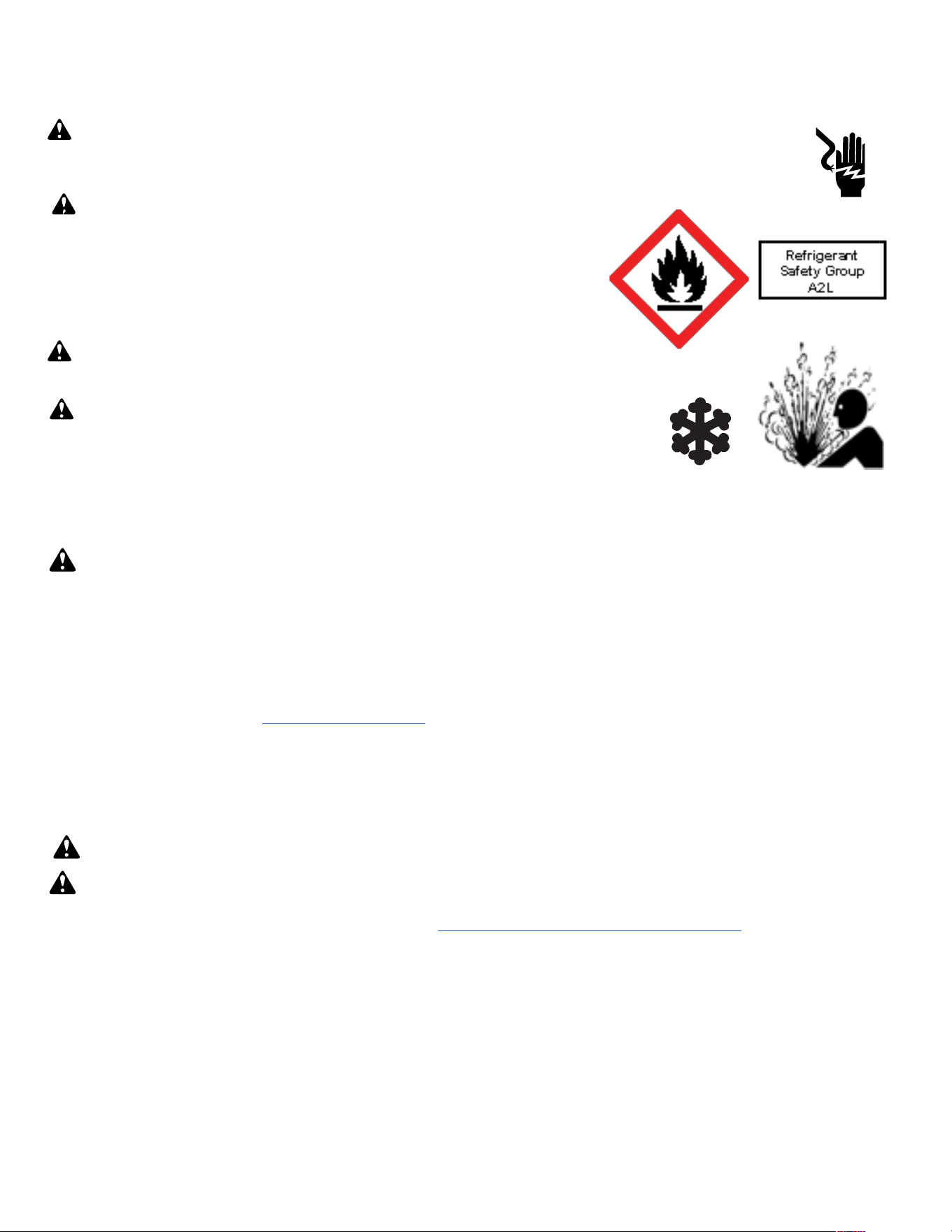
86
R-32 SEALED SYSTEM REPAIRS
Refrigerant Charging
NOTE: Always weigh in refrigerant based on the model nameplate.
Warning:
• Ensure that contamination of different refrigerants does not occur when using charging equipment.
• Hoses or lines shall be as short as possible to minimise the amount of refrigerant contained in them.
• Charge unit with refrigerant cylinder in the inverted position to obtain liquid refrigerant.
• Charge the unit according to the amount on the name plate matching the unit.
• Extreme care shall be taken not to overfill the REFRIGERATING SYSTEM.
• Prior to recharging a system, it shall be pressure-tested with the dry nitrogen.
NOTE: Because the refrigerant system is a sealed system, service process tubes will have to be installed. First install a line tap and recover
refrigerant from system. Refer to the Refrigerant removal section of this manual for procedures.
The acceptable method for charging the sealed system is the Weighed in Charge Method. The weighed in charge method is applicable to all units. It is
the preferred method to use, as it is the most accurate.
The weighed in method should always be used whenever a charge is removed from a unit such as for a leak repair, compressor replacement, or when
there is no refrigerant charge left in the unit. To charge by this method, requires the following steps:
• Warning: Ensure sufficient ventilation at the repair place.
Warning: Ensure there are no open flame sources or hot surfaces that exceed 1200˚F in the work area.
1. Recover Refrigerant in accordance with EPA regulations. (Refer to Refrigerant Removal, Recovery, and Evacuation Section).
NOTE: If a low charge is suspected weigh recovered refrigerant and compare to unit nameplate.
NOTE: Access valves must be removed after charging is complete to return this unit to a sealed system.
2. Weigh in the refrigerant charge with the proper quantity of R-32 refrigerant per model nameplate.
3. Crimp the process tube and solder the end shut.
4. Start unit, and verify performance.
NOTE: EPA Section 608 regulations require that if a system is charged with flammable refrigerant it must have red markings on the access ports
(Process tube).
WARNING: Electrical Shock Hazard
Disconnect all power to the unit before starting maintenance. All electrical connections and wiring MUST be installed by a qualified electrician
and conform to all codes which have jurisdiction. Failure to do so can result in property damage, severe electrical shock or death.
WARNING: This Product uses R-32 Refrigerant
Do not use means to accelerate the defrosting process or to clean, other than those recommended by the
manufacturer.
When not installed, the appliance shall be stored in a room without continuously operating ignition
sources (for example: open flames, an operating gas appliance or an operating electric heater.
Do not pierce or burn.
Be aware that refrigerants may not contain an odor.
WARNING:
Refrigeration System under High pressure
Do not puncture, heat, expose to flame or incinerate. Only certified refrigeration technicians should service this equipment. R32 systems
operate at higher pressures than R22 equipment. Appropriate safe service and handling practices must be used.
WARNING:
Freeze Hazard
Proper safety procedures must be followed, and all PPE must be utilized when working with liquid refrigerant. Failure to
comply could result in minor to moderate injury.
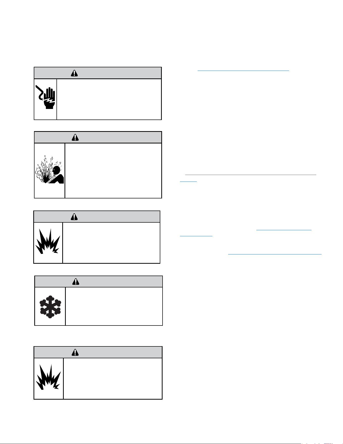
87
R-32 SEALED SYSTEM REPAIRS
Compressor Replacement
WARNING
ELECTRIC SHOCK HAZARD
Turn off electric power before service or
installation. Extreme care must be used, if it
becomes necessary to work on equipment with
power applied.
Failure to do so could result in serious injury or
death.
1. Be certain to perform all necessary electrical and refrigeration tests
to be sure the compressor is actually defective before replacing.
2. Recover all refrigerant from the system though the process tubes.
Refer to Refrigerant Removal, Recovery, and Evacuation Section of this
manual).
PROPER HANDLING OF RECOVERED REFRIGERANT ACCORDING TO
EPA REGULATIONS IS REQUIRED.
3. After all refrigerant has been recovered, cut and remove
compressor. Be certain to have both suction and discharge process
tubes open to atmosphere.
4. Carefully pour a small amount of oil from the suction stub of the
defective compressor into a clean container.
5. Using an acid test kit (one shot or conventional kit), test the oil for
acid content according to the instructions with the kit.
6. If any evidence of a burnout is found, no matter how slight, refer
to Compressor Replacement -Special Procedure in Case of Compressor
Burnout.
7. Install the replacement compressor.
CAUTION: Seal all openings on the defective compressor immediately.
Compressor manufacturers will void warranties on units received not
properly sealed. Do not distort the manufacturers tube connections.
8. Braze all connections. Refer to the Component Replacement/
Brazing section of this manual.
9. Charge system with proper amount of refrigerant per the model
nameplate. Refer to the Refrigerant charging section of this manual.
WARNING
EXPLOSION HAZARD
The use of nitrogen requires a pressure
regulator. Follow all safety procedures and
wear protective safety clothing etc.
Failure to follow proper safety procedures
could result in serious injury or death.
FREEZE HAZARD
Proper safety procedures must be followed,
and proper protective clothing must be worn
when working with liquid refrigerant.
Failure to follow these procedures could
result in minor to moderate injury.
CAUTION
WARNING
NEVER, under any circumstances,
liquid charge a rotary-compressor
through the LOW side. Doing so
would cause permanent damage to
the new compressor. Use a charging
adapter.
WARNING
HIGH PRESSURE HAZARD
Sealed Refrigeration System contains refrigerant
and oil under high pressure.
Proper safety procedures must be followed,
and PPE must be utilized
when working with refrigerants.
Failure to follow these procedures could
result in serious injury or death.
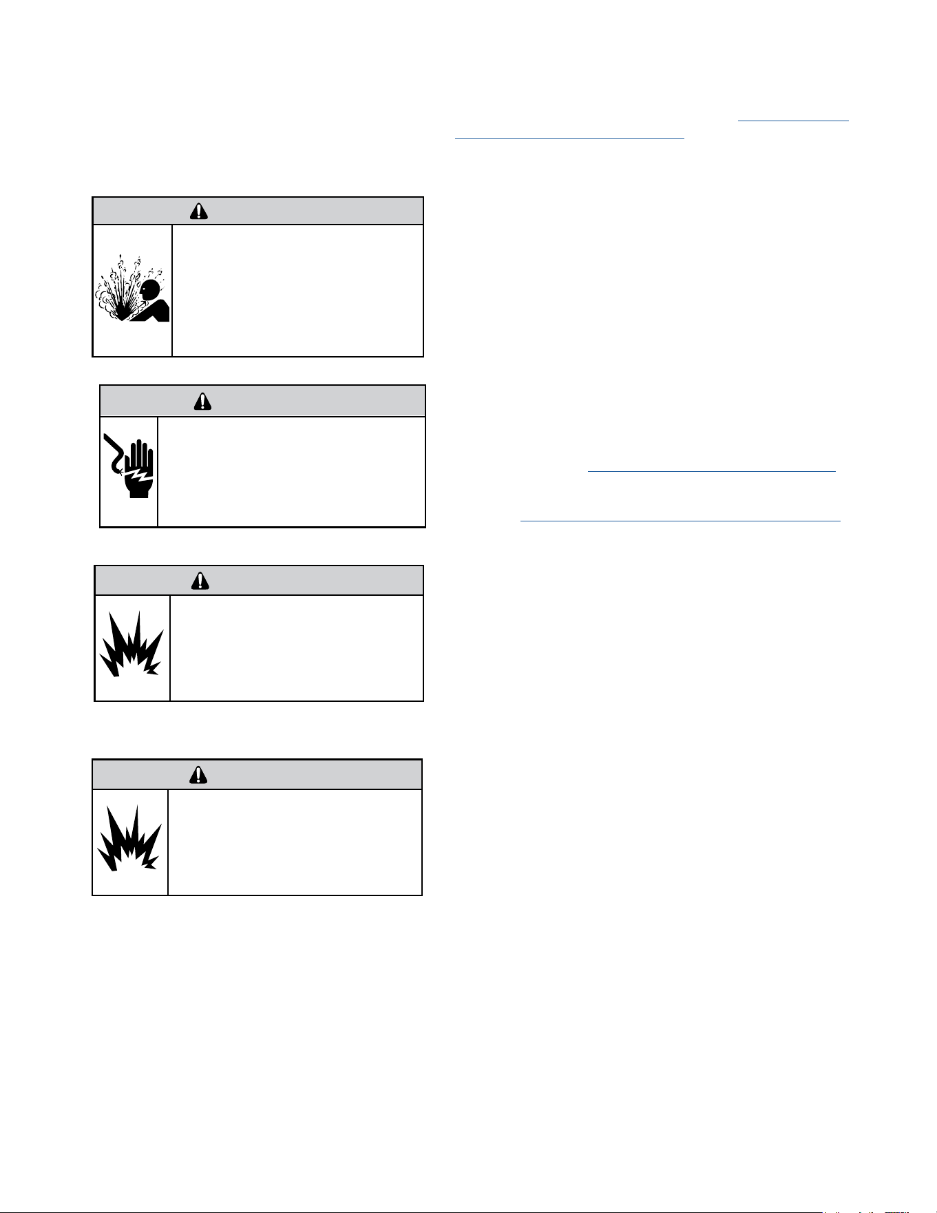
88
R-32 SEALED SYSTEM REPAIRS
Compressor Replacement -Special Procedure in Case of Compressor Burnout
WARNING
HIGH PRESSURE HAZARD
Sealed Refrigeration System contains refrigerant
and oil under high pressure.
Proper safety procedures must be followed,
and PPE must be utilized
when working with refrigerants.
Failure to follow these procedures could
result in serious injury or death.
WARNING
ELECTRIC SHOCK HAZARD
Turn off electric power before service or
installation. Extreme care must be used, if it
becomes necessary to work on equipment with
power applied.
Failure to do so could result in serious injury or
death.
WARNING
EXPLOSION HAZARD
The use of nitrogen requires a pressure
regulator. Follow all safety procedures and
wear protective safety clothing etc.
Failure to follow proper safety procedures
could result in serious injury or death.
1. Recover all refrigerant and oil from the system. Refer to Refrigerant
Removal, Recovery, and Evacuation Section of this manual.
2. Cut and remove compressor and capillary tube from the system.
CAUTION: Seal all openings on the defective compressor immediately.
Compressor manufacturers will void warranties on units received not
properly sealed. Do not distort the manufacturers tube connections.
3. Flush evaporator condenser and all connecting tubing with dry
nitrogen or equivalent. Use A2L approved flushing agent to remove all
contamination from system. Inspect suction and discharge line for carbon
deposits. Remove and clean if necessary. Ensure all acid is neutralized.
4. Reassemble the system, including a new capillary tube assembly and
strainers.
5. Install a dual port suction line drier on the common suction line and
remove when the pressure differential across the drier ports reaches 3
psi. or greater.
6. Braze all connections. Refer to the Brazing section of this manual.
7. Charge system with proper amount of refrigerant per the model
nameplate. Refer to the refrigerant charging section of this manual.
WARNING
NEVER, under any circumstances,
liquid charge a rotary-compressor
through the LOW side. Doing so
would cause permanent damage to
the new compressor. Use a charging
adapter.
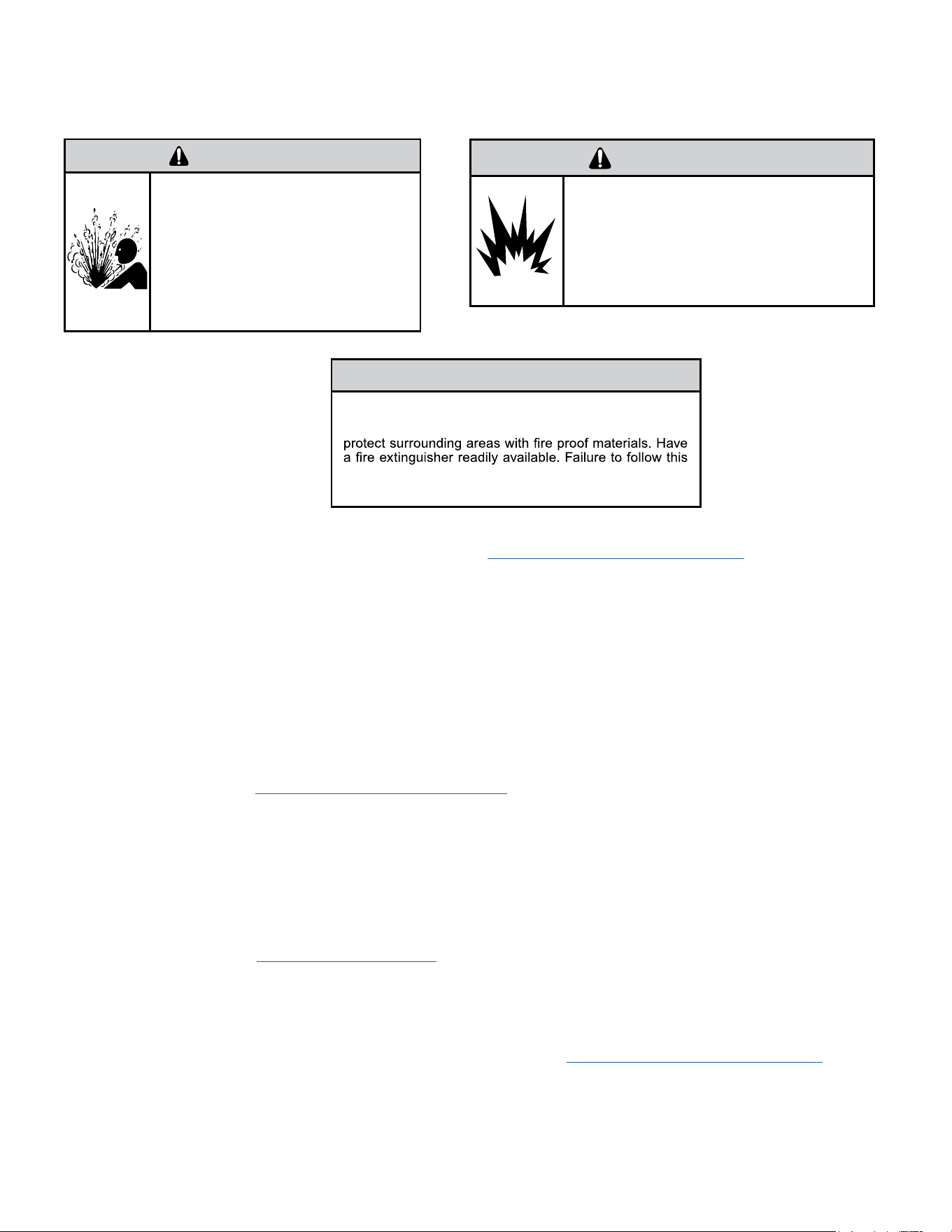
89
R-32 SEALED SYSTEM REPAIR
Replace The Reversing Valve
WARNING
HIGH PRESSURE HAZARD
Sealed Refrigeration System contains refrigerant
and oil under high pressure.
Proper safety procedures must be followed,
and PPE must be utilized
when working with refrigerants.
Failure to follow these procedures could
result in serious injury or death.
NOTICE
FIRE HAZARD
The use of a torch requires extreme care and proper
judgment. Follow all safety recommended precautions and
notice could result in moderate to serious property damage.
1. Recover all refrigerant from the system though the process tubes. Refer to Refrigerant Removal, Recovery, and Evacuation Section of this manual).
PROPER HANDLING OF RECOVERED REFRIGERANT ACCORDING TO EPA REGULATIONS IS REQUIRED.
2. Remove solenoid coil from reversing valve. If coil is to be reused, protect from heat while changing valve.
NOTE: When brazing a reversing valve into the system, it is of extreme importance that the temperature of the valve does not exceed 250°F at any
time.
Wrap the reversing valve with a large rag saturated with water. “Re-wet” the rag and thoroughly cool the valve after each brazing operation of the four
joints involved.
The wet rag around the reversing valve will eliminate conduction of heat to the valve body when brazing the line connection.
3. Cut all lines from reversing valve. Refer to the Brazing section of this manual.
4. Clean all excess braze from all tubing so that they will slip into fittings on new valve.
5. Remove solenoid coil from new valve.
6. Protect new valve body from heat while brazing with plastic heat sink (Thermo Trap) or wrap valve body with wet rag.
7. Fit all lines into new valve and braze lines into new valve.
8. Braze all connections. Refer to the Brazing section of this manual.
9. Pressurize with nitrogen to 550 psi and leak test all connections with a leak detection fluid. Repair any leaks found.
10. Once the sealed system is leak free, install solenoid coil on new valve.
11. Charge system with proper amount of refrigerant per the model nameplate. Refer to the refrigerant charging section of this manual.
WARNING
EXPLOSION HAZARD
The use of nitrogen requires a pressure
regulator. Follow all safety procedures and
wear protective safety clothing etc.
Failure to follow proper safety procedures
could result in serious injury or death.
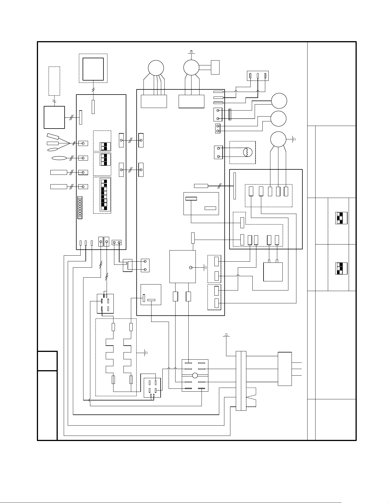
90
WIRING DIAGRAM
Figure 801
共 1 页
TOTAL SHEETS
第 1 页
NO.OF SHEETS
陈庆军
2023-12-06
张 倩
2023-12-06
刘 行
2023-12-06
黄金芳
2023-12-06
孙江浩
2023-12-06
郑兆权
2023-12-06
1:1
积研表002号
广东积微集团有限公司
GUANGDONG GIWEE GROUP CO.,LTD
技术要求
1. 外形尺寸:长、高 (±3mm),布满图纸居中打印;
2. 制件底色为白色,中文字体为黑体,英文字体为 ,图文黑白印刷;印刷内容
正确、不误字意,字迹清晰;
3. 表面光洁平整,无明显脏污,周边整齐,无毛边、刮痕、皱折、残缺、气泡等缺陷;不
允许存在明显的条杠;
有 RoHS2.0 指令要求的物料应符合企业标准 QG-J000.2002-2021《产品中限制使用
有害物质的技术标准(RoHS 指令)》。
材料:乳白PET+覆光膜
接线铭牌
CPT-DV12AGR4-PSA(D).PM-4
BK-BLACK WH-WHITE
BN-BROWN OR-ORANGE
RD-RED
YE/GN-YELLOW/GREEN
BL-BLUE GN-GREEN
1-Reserved
2-Heat pump
3-Electric heater
4-Humidity control fresh air
5-Freeze protect
SW2 MODEL TYPE SWITCH
6-Auto restart
7-Reserved
8-Reserved
9K 12K
INNER FAN CAPACITOR
SW1 FUNCTION(ON-Enable, OFF-Disable)
YE/GN
1 ON,2 OFF,3 OFF 1 OFF,2 ON,3 OFF
COLOR CODE
802022000219
SW3 FUNCTION GUIDANCE
OUTPUT_L
BK
WH
RD
POWER SUPPLY
BL
BK(BN)
U
V
W
E.HEATER2_L
T1
T2
T3
T4
RELAY2
BK(BN)
E.HEATER_N
RELAY1
485 PORT
WIRE
CONTROLLER
IR RECEIVER
3
YE/GN
T5
T6
DOOR
MOTOR
AIR
FAN
FRESH_AIR
1-Fresh Air Enable/Disable
2-Fresh Air CONTINUOUSLY
Running/CYCLES With Indoor Fan
RD
BL
24V FAN
RD
BK
HIGH
LOW
FRESH AIR
FAN SPEED
SWITCH
BL
RD
BK
BL
BL
COM
NO
1
0
4
8
2
6
6
2
8
4
0
1
COM
NO
EMI FILTER
INPUT_N
OUTPUT_N
ACN
ACL
DC-
DC+
L
DC+
L
DC+
DC-
REACTOR
U
V
W
COMP
IPM BOARD
MAINBOARD
POWER BOARD
TERMINAL BLOCK
INPUT_L
RELAY
4
3
MB_COMM
POWER&RELAYS
MB_COMM
DISPLAY
MOD_COM
CONTROL
POWER&RELAYS
INFAN
OUTFAN
INNER
OUTER FAN
SW2
SW3
ON
ON
1
2 3
1
2
RD
BL
BK
WH
BL
PANEL
BL
FAN
OUTER
FAN
BK
BK
BK(BN)
WH(BL)
GN(YE/GN)
RD
OR
E.HEATER1_L
BL
BK
BK
FUSE
FUSE
YE/GN
COM
NO
4-WAY
REVERSING VALVE
1
2 3
4
5 6
7
8
SW1
SW2
ON
1
2 3
SW2
ON
1
2 3
ON
H-COM
HEATER1
HEATER2
TRANS_IN
TRANS_24V
T5
6
3
12
6
22
IN
OUT
6
CIRCUIT DIAGRAM
Note2
Note2
RD
ELECTRIC HEATER2
FUSE
FUSE
ELECTRIC HEATER1
T1-T3
T4
TRANSFORMER
REMOTE THERMOSTAT
BK
2
Note1
Note1
BL
POWER CONNECTOR
YE/GN
BK
WH
2
BL
BK
RD
T6
2
JUMPER
Note3
Note3
BL
BK
RD
BL
RD
BK
CAPACITOR
DC-
FA+
FAL
FAH
EARTH
WARNING:
SWITCHES SW2 ARE FOBBIDEN TO CHANGE,
OTHERWISE UNIT WILL FAIL TO WORK AND MAY
BE DAMAGED !
V.0

91
APPENDIX
Interactive Parts Viewer
All Friedrich Service Parts can be found on our online interactive parts viewer.
Please click on the link below:
Interactive Parts Viewer
For Further Assistance contact Friedrich customer service at (1-800-541-6645).
Limited Warranty
Current warranty information can be obtained by referring to
https://www.friedrich.com/professional/support/product-resources
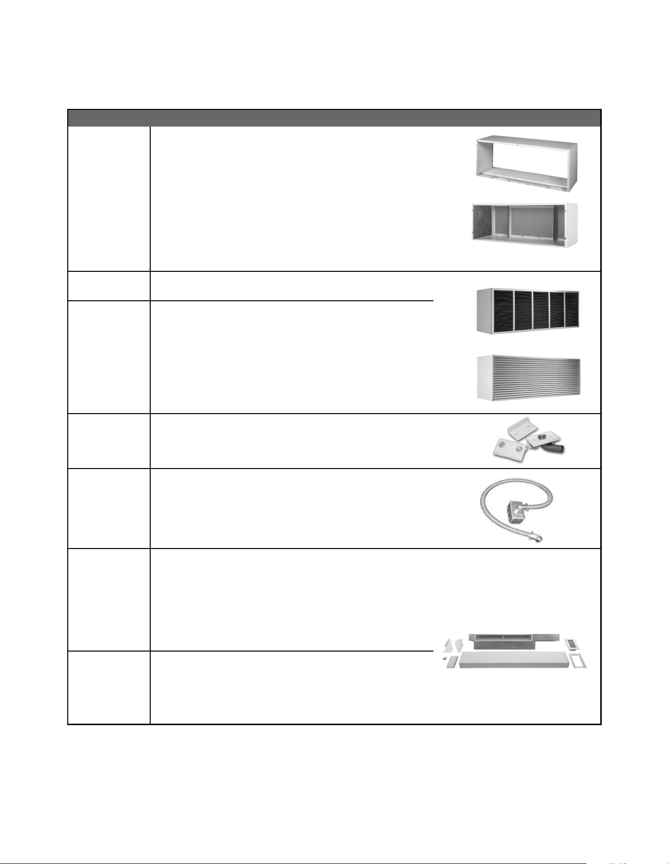
92
APPENDIX
ACCESSORIES
32
New Construction Accessories
PDXWSA
PDXWSEXT18
PDXWSEXT24
PDXWSEXT
WALL SLEEVE Galvanized zinc coated steel is prepared in an 11-
step process, then powder coated with a polyester nish and cured
in an oven for exceptional durability. The wall sleeve is insulated for
sound absorption and thermal efciency, 16" H x 42" W x 13
3
/4" D.
DEEP WALL SLEEVE For walls up to 17
1
/2" deep.
DEEP WALL SLEEVE For walls up to 23
1
/2" deep.
CUSTOM DEEP WALL SLEEVE One piece extended wall sleeve for walls
from 13
1
/4" to 25
1
/2" deep are available by special order.
PXGA
GRILLE Standard, stamped aluminium, anodized to resist chalking and
oxidation.
PXAA
PXBG
PXSC
ARCHITECTURAL GRILLES C on s i s t of h e av y - g a ug e 6 0 6 3 - T 5 a l um i n u m
alloy: 42" W x 16" H x 1
1
/8" D
PXAA – Clear, extruded aluminum
PXBG – Beige acrylic enamel
PXSC – Also available in custom colors.
PXDR10
CONDENSATE DRAIN KIT Attaches to the bottom of the wall sleeve for
internal draining of condensate or to the rear wall sleeve ange for external
draining. Recommended on all units to remove excess condensate.
Packaged in quantities of ten.
PXCJA
CONDUIT KIT WITH JUNCTION BOX Hard wire conduit kit with junct io n box
for 208/230V and 265V units (subbase not required). Kit includes a
means of quick disconnect for easy removal of the chassis. *Required
for 265V installations.
PDXDAA LATERAL DUCT ADAPTER Attaches to the Friedrich PTAC/PTHP unit to
direct up to 35% of the total airow to a second room. The unit-mounted
duct plenum features a front-mounted aluminum grille that has two
positions to provide the most optimal air direction. The air may be directed
to either the left or the right of the unit through the supplied 3
1
/2" H x 7" W x
47" L plenum. Plenum may be cut to length by the installer. Kit includes duct
plenum, front grille, 47" duct extension, duct discharge grille, duct end cap
and all necessary mounting hardware.
PDXDEA
LATERAL DUCT EXTENSION Additional 3
1
/2" H x 7" W x 47" L plenum
for use with the LATERAL DUCT ADAPTER. A maximum of 3 duct
extensions total may be used. Note: Ducted airow is reduced as duct
length is increased.
PXAA
PXGA
Deep wall sleeve PDXWSEXT18 shown with weather panel
PDXWSA
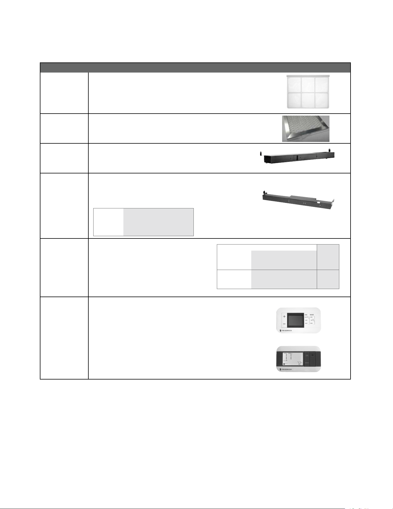
93
APPENDIX
ACCESSORIES
33
New Construction Accessories
PXFTA REPLACEMENT FILTER PACK These are original equipment return air
lters. They are reusable and can be cleaned by vacuuming, washing, or
blowing out, and are sold in convenient ten-packs. (Two lters per chassis).
PXFAFT10 REPLACEMENT FILTER PACK
Merv 8 lters. 10 pack. Each PTAC requires
1 lter.
PXSBA DECORATIVE SUBBASE Provide s unit suppor t for wall s les s than six inches
thick. Includes leveling legs, side filler panels and mounting brackets
for electrical accessories. Accepts circuit breaker, power disconnect
switch, or conduit kit.
PXSB ELECTRICAL SUBBASE Provides unit support for walls less than six inches
thick. Includes leveling legs, side ller panels, mounting brackets, a
plug-in receptacle and field-wiring access. The subbase also includes
electrical knockouts for a power disconnect switch or circuit breaker.
PXSB23020 Electrical Subbase - 230V 15 & 20A
PXSB23030 Electrical Subbase - 230V 30A
PXSB26515 Electrical Subbase - 265V 15A
PXSB26520 Electrical Subbase - 265V 20A
PXSB26530 Electrical Subbase - 265V 30A
PXPCFA POWER CORDS
Universal power cords enable properties to select the
appropriate heater size. Reference the adjacent table
for power cord options
*Cannot be used on PVH09K3FA.
RT7
RT7P
DIGITAL REMOTE THERMOSTATS
RT7 Wired single stage cool, single stage heat for PDE models or single
stage cool, dual stage heat for PDH model thermostat features high/low
fan speed switch. Thermostat is hard wired and can be battery powered or
unit powered. Features backlit display and multiple conguration modes.
For use on Friedrich PTACs and Vert-I-Paks.
RT7P Wired, programmable single stage cool, single stage heat for PDE
models or single stage cool, dual stage heat for PDH model thermostat
features high/low fan speed switch. Thermostat is hard wired and can be
battery powered or unit powered. Features backlit display and multiple
conguration modes. For use on Friedrich PTACs and Vert-I-Paks.
Length
PXPCFA23015 LCDI 230V 15A Cord - 2.5 kW 67 in.
PXPCFA23020 LCDI 230V 20A Cord - 3.5 kW 67 in.
PXPCFA23030* LCDI 230V 30A Cord - 5.0 kW 67 in.
PXPCFA26515 Non-LCDI 265V 15A Cord - 2.5 kW 27 1/2 in.
PXPCFA26520 Non-LCDI 265V 20A Cord - 3.5 kW 27 1/2 in.
PXPCFA26530* Non-LCDI 265V 30A Cord - 5.0 kW 27 1/2 in.
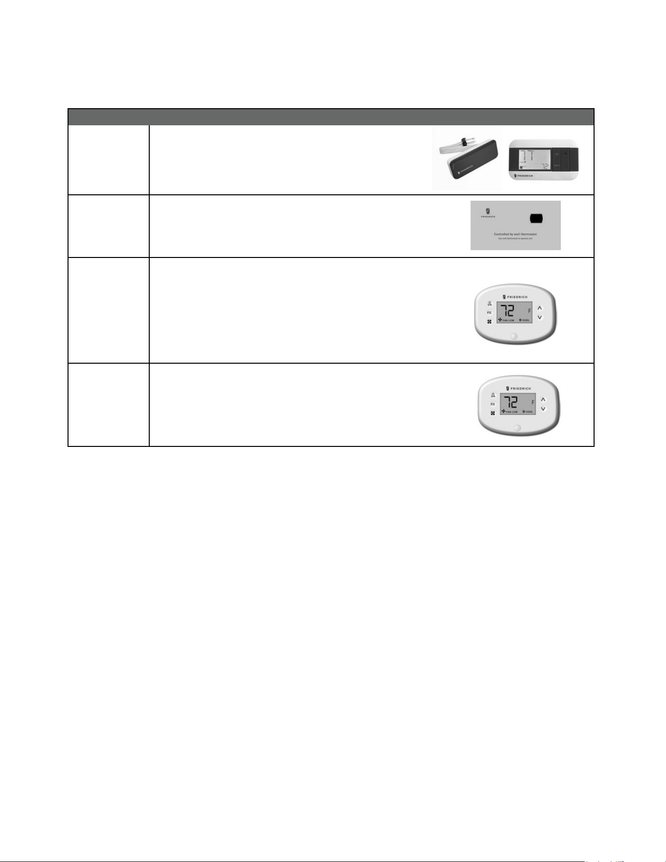
94
34
New Construction Accessories
WRT2 WIRELESS DIGITAL REMOTE THERMOSTAT Single stage cool, single
stage heat for PDE models or single stage cool, dual stage heat for PDH
model thermostat features high/low fan speed switch. Thermostat is
wireless and is battery powered. Features backlit display and multiple
conguration modes. For use on Friedrich PTACs and Vert-I-Paks.
PDXRTB REMOTE THERMOSTAT ESCUTCHEON KIT T hi s kit cont ains ten es c u tcheons
that can be placed over the factory control buttons when a remote wall
mounted thermostat is used. The escutcheon directs the guest to the wall
the rmo st at for ope rat io n and reta ins the LED w in do w to disp lay erro r code s
and diagnostic information.
EMRT2
EMWRT2
ENERGY MANAGEMENT THERMOSTATS
EMRT2
Wired thermostat with occupancy sensor.
EMWRT2
Wireless thermostat with occupancy sensor.
EMOCT EMRAF EMRHCF
Online connection kit. Remote access fee. Remote humidity control fee.
VRPXEMRT2
(Preferred
FreshAire
Thermostat)
VRPXEMWRT2
Wired and wireless thermostat and occupancy sensor 12v. Full inverter control.
Designed to maximize features and benets of FreshAire system.
Wireless wall controller and occupancy sensor-12v. Full inverter control.
Designed to maximize features and benets of FreshAire system.
*NOTE: The FreshAire PTAC must be paired with wall controller VRPXEMRT2 or VRPXEMWRT2 to operate as a fully variable speed unit.
When used with other compatible thermostats, the unit will operate at multiple speeds in either cooling or heating mode.
APPENDIX
ACCESSORIES
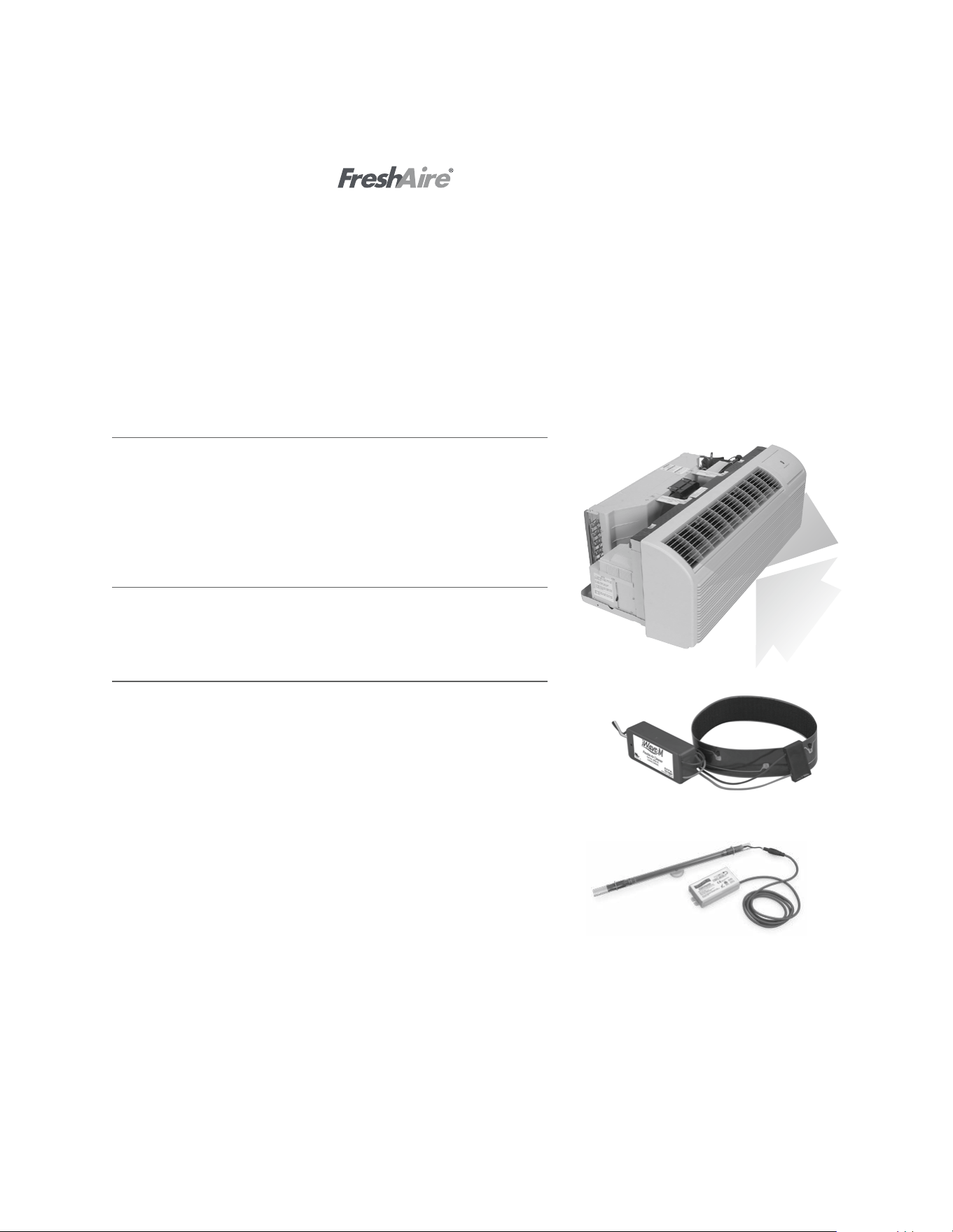
95
35
FreshAire
®
Make Up Air (MUA) & Filtration
Award-winning FreshAire MUA system helps achieve ASHRAE 62.1-2013 require-
ments, and brings up to 52 CFM of conditioned, MERV 8 filtered, outside air into
the space. Patented FreshAire technology uses the Precision Inverter compressor
and main cooling system to optimize temperature and humidity level of incoming
air while MERV 8 filtration traps particles and pollutants.
Standard on FreshAire PTAC
FreshAire
®
Purier APWM1
FreshAire Purifier by iWaves features needlepoint bi-polar ionization to address
any mold, bacteria, virus, allergens, and VOC's that may be in your air stream to
ensure delivery of healthy, clean, purified air.
Friedrich
®
UV UVT1
Germicidal UV light kits have been tested and certified for use on Friedrich
PTACs. The UV kit can be installed on the fan coil and is designed to disinfect
surfaces and the air as it circulates through the ventilation system. UV light can
kill airborne bacteria, viruses, mold, reduce maintenance costs and extend the
life of an HVAC system
Friedrich PTAC with
The COVID-19 global pandemic transformed the way the lodging industry meets the comfort and safety needs for guests.
As your room air experts, Friedrich remains committed to improving guest comfort and safety with our newest innovation,
FreshAire
®
IAQ solutions - a suite of indoor air quality accessories for use with Friedrich Air Conditioners, all with one dedicated purpose
- healthy indoor air. FreshAire® IAQ solutions incorporate ASHRAE-recommended protocol* to address indoor air quality and airborne
transmissions.
This suite of products include industry-leading air quality technologies such as MERV 13 filtration,UV germicidal light and bi-polar
ionization. Together, they represent a major leap forward in integrated HVAC air purification and rebuilding confidence for indoor
environments.
*Based on ASHRAE Guidance for Building Operations During the COVID-19 Pandemic
Return air
IAQ
APPENDIX
ACCESSORIES
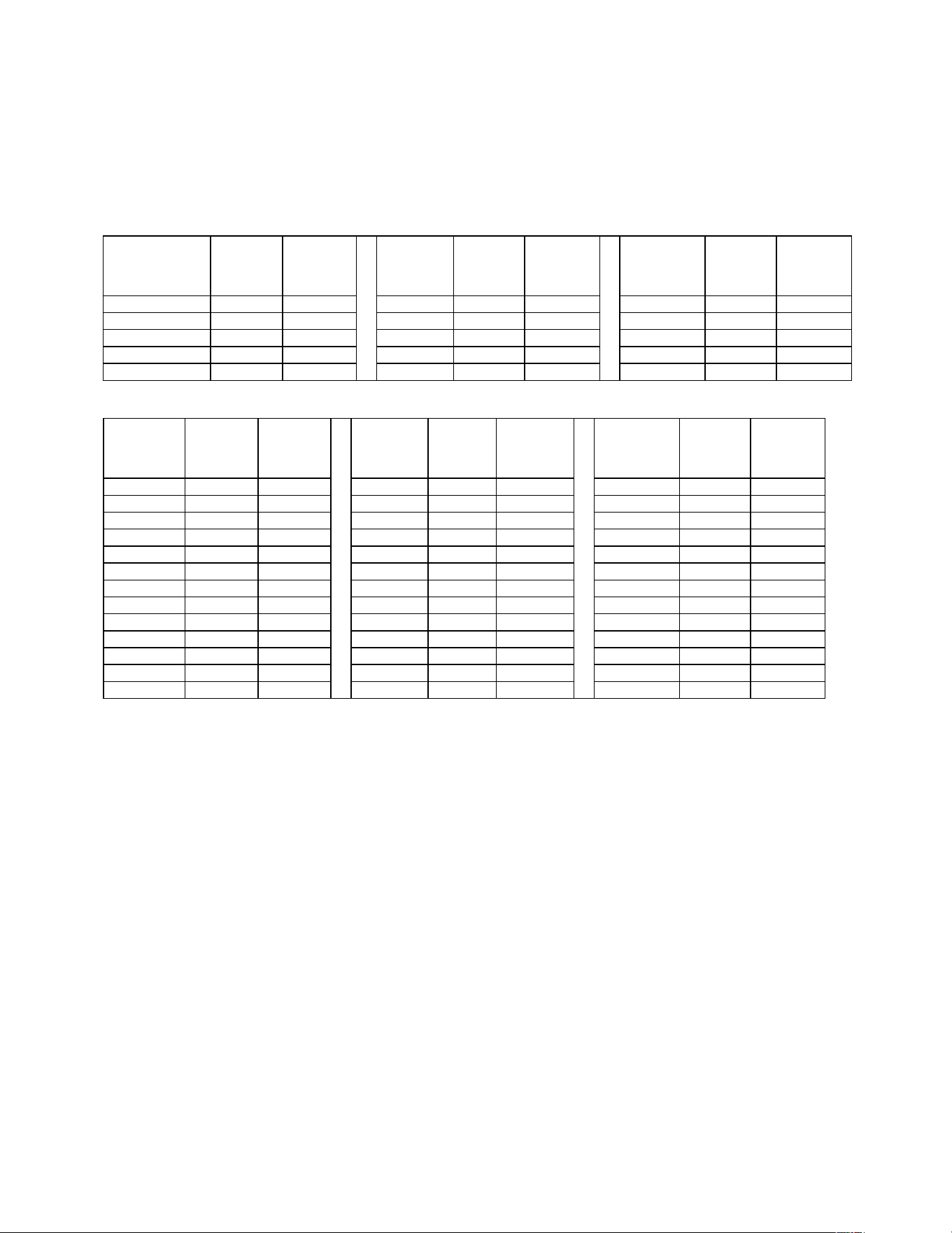
96
APPENDIX
Appendix 1 Reference Sheet of Celsius and Fahrenheit
Fahrenheit
display
temperature
(°F)
Fahrenheit
(°F)
Celsius(°C)
Fahrenheit
display
temperature
(°F)
Fahrenheit
(°F)
Celsius(°C)
Fahrenheit
display
temperature
(°F)
Fahrenheit
(°F)
Celsius(°C)
32/33 32 0 55/56 55.4 13 79/80 78.8 26
34/35 33.8 1 57/58 57.2 14 81 80.6 27
36 35.6 2 59/60 59 15 82/83 82.4 28
37/38 37.4 3 61/62 60.8 16 84/85 84.2 29
39/40 39.2 4 63 62.6 17 86/87 86 30
41/42 41 5 64/65 64.4 18 88/89 87.8 31
43/44 42.8 6 66/67 66.2 19 90 89.6 32
45 44.6 7 68/69 68 20 91/92 91.4 33
46/47 46.4 8 70/71 69.8 21 93/94 93.2 34
48/49 48.2 9 72 71.6 22 95/96 95 35
50/51 50 10 73/74 73.4 23 97/98 96.8 36
52/53 51.8 11 75/76 75.2 24 99 98.6 37
54 53.6 12 77/78 77 25
Conversion formula for Fahrenheit degree and Celsius degree: Tf=Tcx1.8+32
Set temperature
Ambient temperature
Fahrenheit
display
temperature
(°F)
Fahrenheit
(°F)
Celsius(°C)
Fahrenheit
display
temperature
(°F)
Fahrenheit
(°F)
Celsius
(°C)
Fahrenheit
display
temperature
(°F)
Fahrenheit
(°F)
Celsius
(°C)
61 60.8 16 69/70 69.8 21 78/79 78.8 26
62/63 62.6 17 71/72 71.6 22 80/81 80.6 27
64/65 64.4 18 73/74 73.4 23 82/83 82.4 28
66/67 66.2 19 75/76 75.2 24 84/85 84.2 29
68 68 20 77 77 25 86 86 30
97
Temp Resis Temp Resis Temp Resis Temp Resis Temp Resis
-33 130100 7 34252 47 10785 57 8275 97 3119
-32 125518 8 33209 48 10499 58 8063 98 3048
-31 121114 9 32202 49 10221 59 7857 99 2980
-30 116881 10 31228 50 9952 60 7657 100 2913
-29 112811 11 30288 51 9690 61 7462 101 2848
-28 108898 12 29378 52 9437 62 7273 102 2785
-27 105131 13 28499 53 9190 63 7090 103 2723
-26 101511 14 27650 54 8952 64 6911 104 2662
-25 98029 15 26828 55 8720 65 6738 105 2604
-24 94676 16 26034 56 8494 66 6569 106 2546
-23 91453 17 25266 57 8275 67 6406 107 2491
-22 88349 18 24523 58 8063 68 6247 108 2436
-21 85362 19 23805 59 7857 69 6092 109 2383
-20 82486 20 23110 60 7657 70 5942 110 2331
-19 79719 21 22437 61 7462 71 5796 111 2281
-18 77052 22 21787 62 7273 72 5654 112 2231
-17 74486 23 21158 63 7090 73 5515 113 2183
-16 72014 24 20548 64 6911 74 5381 114 2137
-15 69633 25 19959 65 6738 75 5251 115 2091
-14 67338 26 19388 66 6569 76 5124 116 2046
-13 65127 27 18836 67 6406 77 5000 117 2003
-12 62996 28 18301 68 6247 78 4880 118 1960
-11 60943 29 17783 69 6092 79 4763 119 1919
-10 58965 30 17282 70 5942 80 4649 120 1878
-9 57055 31 16796 71 5796 81 4538 121 1839
-8 55216 32 16325 72 5654 82 4431 122 1800
-7 53442 33 15870 73 5515 83 4326 123 1763
-6 51732 34 15428 74 5381 84 4224 124 1726
-5 50082 35 15001 75 5251 85 4125 125 1690
-4 48490 36 14586 76 5124 86 4028 126 1655
-3 46955 37 14184 77 5000 87 3934 127 1621
-2 45473 38 13795 48 10499 88 3842 128 1588
-1 44044 39 13418 49 10221 89 3753 129 1555
0 42664 40 13052 50 9952 90 3666 130 1524
1 41332 41 12698 51 9690 91 3582 131 1493
2 40047 42 12354 52 9437 92 3499 132 1462
3 38805 43 12021 53 9190 93 3419 133 1433
4 37607 44 11698 54 8952 94 3341 134 1404
5 36450 45 11384 55 8720 95 3265 135 1375
6 35332 46 11080 56 8494 96 3191 136 1348
137 1321 162 812 187 517 212 339 237 229
138 1294 163 797 188 508 213 334 238 226
139 1269 164 782 189 499 214 329 239 222
140 1244 165 768 190 491 215 323 240 219
APPENDIX
Appendix 2 Resistance Table of Thermistors (5K)
98
Temp Resis Temp Resis Temp Resis Temp Resis Temp Resis
141 1219 166 754 191 482 216 318 241 216
142 1195 167 740 192 474 217 313 242 212
143 1171 168 727 193 466 218 308 243 209
144 1148 169 713 194 458 219 303 244 206
145 1126 170 700 195 450 220 298 245 203
146 1104 171 688 196 443 221 294 246 200
147 1083 172 675 197 435 222 289 247 197
148 1062 173 663 198 428 223 285 248 194
149 1041 174 651 199 421 224 280 249 191
150 1021 175 640 200 414 225 276 250 189
151 1001 176 628 201 407 226 271
152 982 177 617 202 400 227 267
153 964 178 606 203 394 228 263
154 945 179 595 204 387 229 259
155 927 180 585 205 381 230 255
156 910 181 574 206 374 231 251
157 893 182 564 207 368 232 247
158 876 183 554 208 362 233 244
159 859 184 545 209 356 234 240
160 843 185 535 210 351 235 236
161 828 186 526 211 345 236 233
APPENDIX
Appendix 2 Resistance Table of Thermistors (5K) (Cont)

99
Temp. (°F) Resistance (kΩ) Temp. (°F) Resistance( kΩ) Temp. (°F) Resistance (kΩ) Temp. (°F) Resistance (kΩ)
-20.2 853.5 50 98 120.2 18.34 190.4 4.754
-18.4 799.8 51.8 93.42 122 17.65 192.2 4.609
-16.6 750 53.6 89.07 123.8 16.99 194 4.469
-14.8 703.8 55.4 84.95 125.6 16.36 195.8 4.334
-13 660.8 57.2 81.05 127.4 15.75 197.6 4.204
-11.2 620.8 59 77.35 129.2 15.17 199.4 4.079
-9.4 580.6 60.8 73.83 131 14.62 201.2 3.958
-7.6 548.9 62.6 70.5 132 4/5 14.09 203 3.841
-5.8 516.6 64.4 67.34 134.6 13.58 204.8 3.728
-4 486.5 66.2 64.33 136.4 13.09 206.6 3.619
-2.2 458.3 68 61.48 138.2 12.62 208.4 3.514
-0.4 432 69.8 58.77 140 12.17 210.2 3.413
1.4 407.4 71.6 56.19 141.8 11.74 212 3.315
3.2 384.5 73.4 53.74 143.6 11.32 213.8 3.22
5 362.9 75.2 51.41 145.4 10.93 215.6 3.129
6.8 342.8 77 49.19 147.2 10.54 217.4 3.04
8.6 323.9 78.8 47.08 149 10.18 219.2 2.955
10.4 306.2 80.6 45.07 150.8 9.827 221 2.872
12.2 289.6 82.4 43.16 152.6 9.489 222.8 2.792
14 274 84.2 41.34 154.4 9.165 224 3/5 2.715
15.8 259.3 86 39.61 156.2 8.854 226.4 2.64
17.6 245.6 87.8 37.96 158 8.555 228.2 2.568
19.4 232.6 89.6 36.38 159.8 8.268 230 2.498
21.2 220.5 91.4 34.88 161.6 7.991 231.8 2.431
23 209 93.2 33.45 163.4 7.726 233.6 2.365
24.8 198.3 95 32.09 165.2 7.47 235.4 2.302
26.6 199.1 96.8 30.79 167 7.224 237.2 2.241
28.4 178.5 98.6 29.54 168.8 6.998 239 2.182
30.2 169.5 100.4 28.36 170.6 6.761 240.8 2.124
32 161 102.2 27.23 172.4 6.542 242.6 2.069
33.8 153 104 26.15 174.2 6.331 244.4 2.015
35.6 145.4 105.8 25.11 176 6.129 246.2 1.963
37.4 138.3 107.6 24.13 177.8 5.933 248 1.912
39.2 131.5 109.4 23.19 179.6 5.746 249.8 1.863
41 125.1 111.2 22.29 181.4 5.565 251.6 1.816
42.8 119.1 113 21.43 183.2 5.39 253.4 1.77
44.6 113.4 114.8 20.6 185 5.222 255.2 1.725
46.4 108 116.6 19.81 186.8 5.06 257 1.682
48.2 102.8 118.4 19.06 188.6 4.904 258.8 1.64
APPENDIX
Appendix 2 Resistance Table of Thermistors (50K)(Compressor Discharge Sensor)

100
Friedrich Air Conditioning Co.
10001 Reunion Place, Suite 500 • San Antonio, Texas 78216
1-800-541-6645
www.friedrich.com
TECHNICAL SUPPORT
CONTACT INFORMATION
United Products Distributors Inc.
4030A Benson Ave
Halethorpe, MD 21227
888-907-9675
Shivani Refigeration & Air
Conditioning Inc.
2259 Westchester Ave.
Bronx, NY 10462
NEUCO Inc.
515 W Crossroads Parkway
Bolingbrook, IL 60440
312.809.1418
The Gabbert Company
6868 Ardmore
Houston, Texas 77054
713-747-4110
800-458-4110
Johnstone Supply of Woodside
27-01 Brooklyn Queens Expway
Woodside, New York 11377
718-545-5464
800-431-1143
Reeve Air Conditioning, Inc.
2501 South Park Road
Hallandale, Florida 33009
954-962-0252
800-962-3383
Total Home Supply
26 Chapin Rd Ste 1109
Pine Brook, NJ 07058
877-847-0050
https://www.totalhomesupply.com/
brands/Friedrich.html
APPENDIX
Friedrich Authorized Parts Depots