Model PDXWSEXT/EXT18/EXT24
94993000_00 Friedrich Air Conditioning Co. 1/8
10001 Reunion Place, Suite 500 / San Antonio, Texas 78216
(210) 546-0500 / (800) 541-6645 / www.friedrich.com
Installation Instructions
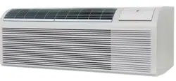
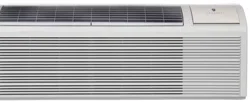
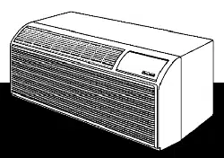
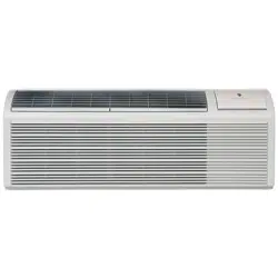
One-Piece Deep Wall Sleeve
For Use with Packaged Terminal Units
Please read these instructions completely before attempting installation.
NOTE: Ensure that the unit is only installed in a wall structurally adequate to support the unit including the sleeve,
chassis and accessories. If the sleeve projects more than 8” into the room, a subbase or other means of support
MUST be used.
Contents:
1. 4 #10x1 Sheet Metal Screws
2. 4 Nut, Speed U
3. 1 Weatherboard
Tools Required: Screwdriver
Step 1. The PXDR10 Drain Kit (optional for new construction), if applicable, must be installed
before the wall sleeve is installed into the wall. See Figure 6.
Step 2. The External Drain (for new construction or unit replacement), if applicable, must be
installed before the wall sleeve is installed in the wall. See Figure 7.
Step 3. From inside the building, position the wall sleeve in the opening and push it into the wall
until it protrudes at least ” on the outside. Do not allow sleeve to be pulled. See Figure 6.
Step 4. Position the wall sleeve with a slight tilt towards the outside to facilitate condensate
drainage. It should be level side-to-side and the front should be ” bubble than the back.
Step 5. Drill two 3/16” holes through each side of the sleeve approximately 4” from top and 4” from
bottom of sleeve. Screw four #10 x 1” screws (included) or appropriate fasteners for your
installation, through the holes in the sides of the wall sleeve.
Step 6. Apply sealant around the wall sleeve where it projects through the inside and outside wall
surfaces. Apply the sealant to the screw heads or the tops of the fasteners used in Step
#5.
Model PDXWSEXT/EXT18/EXT24
94993000_00 Friedrich Air Conditioning Co. 2/8
10001 Reunion Place, Suite 500 / San Antonio, Texas 78216
(210) 546-0500 / (800) 541-6645 / www.friedrich.com
Step 7. If the chassis and exterior grille are to be installed later, leave the weatherboard and center
support in place, otherwise remove and dispose of them.
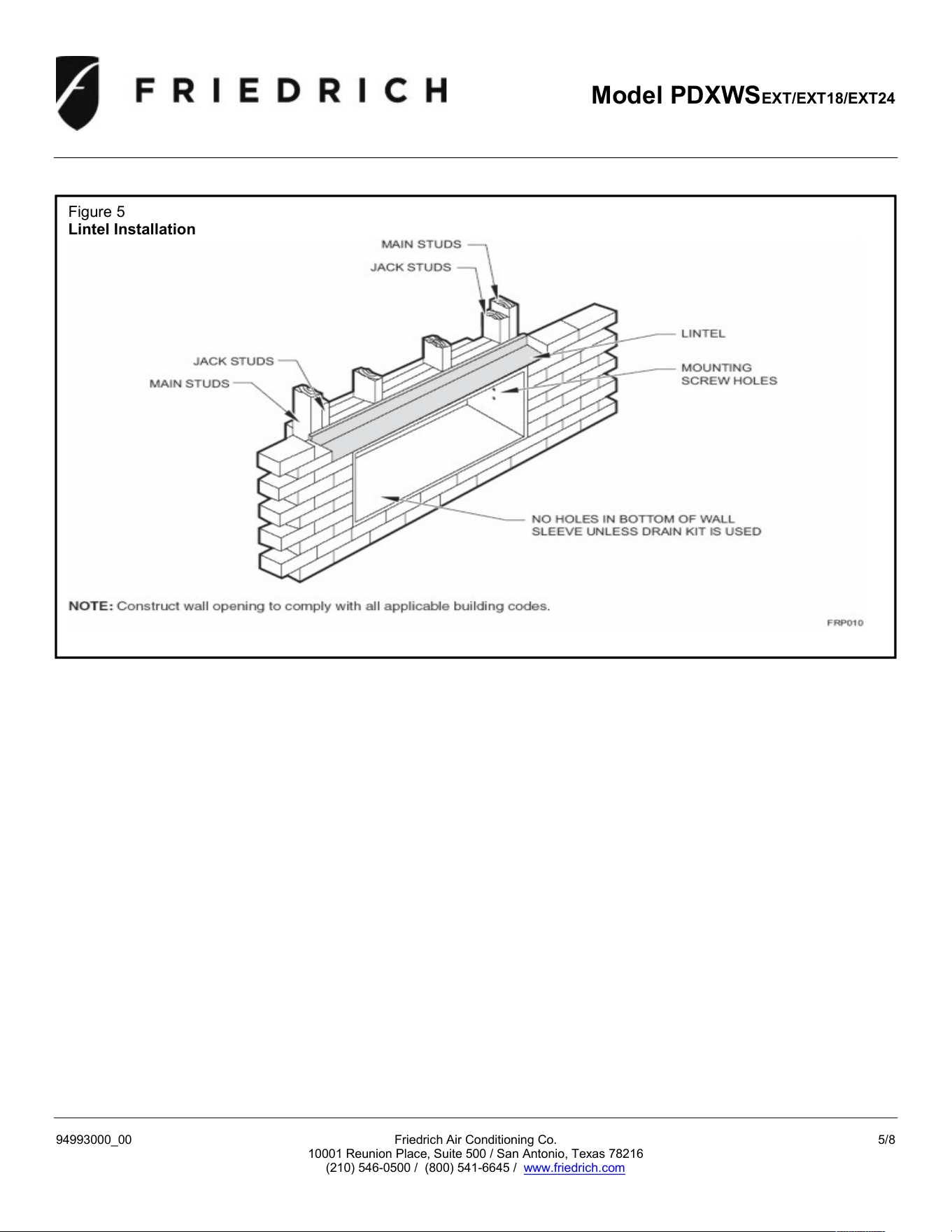
Step 8. Provide a support lintel if the wall sleeve is installed in a concrete or masonry wall. See
Figure 5.
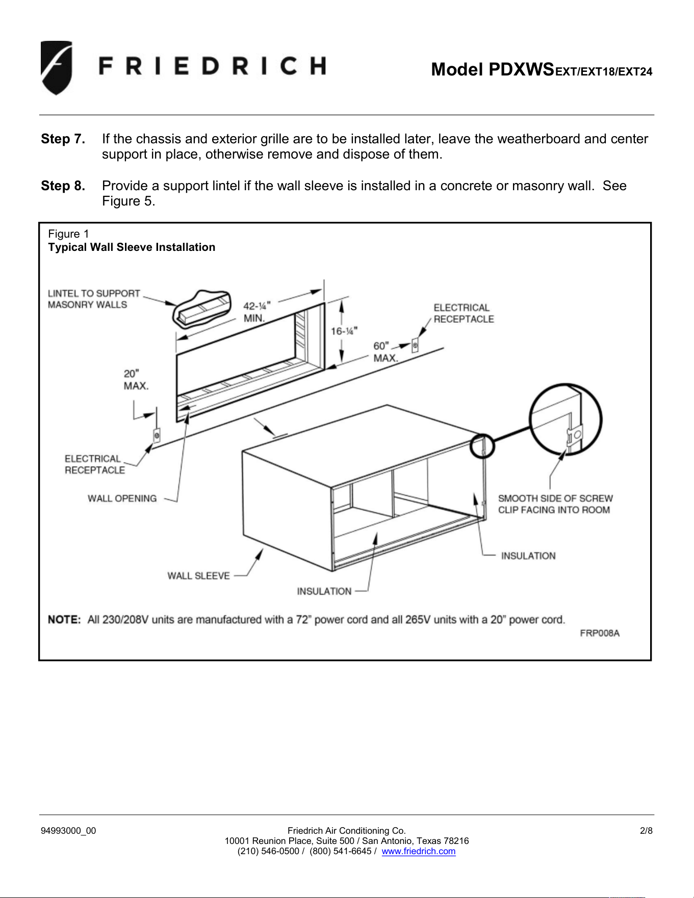
Figure 1
Typical Wall Sleeve Installation
Model PDXWSEXT/EXT18/EXT24
94993000_00 Friedrich Air Conditioning Co. 3/8
10001 Reunion Place, Suite 500 / San Antonio, Texas 78216
(210) 546-0500 / (800) 541-6645 / www.friedrich.com
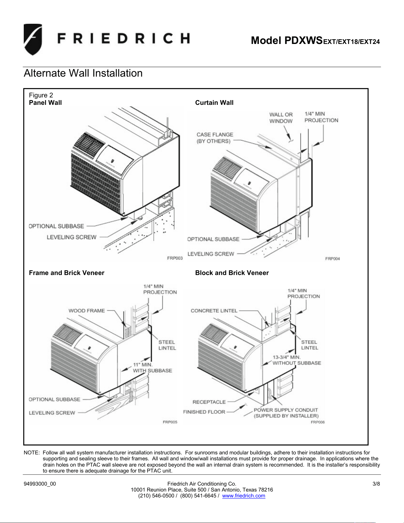
Alternate Wall Installation
NOTE: Follow all wall system manufacturer installation instructions. For sunrooms and modular buildings, adhere to their installation instructions for
supporting and sealing sleeve to their frames. All wall and window/wall installations must provide for proper drainage. In applications where the
drain holes on the PTAC wall sleeve are not exposed beyond the wall an internal drain system is recommended. It is the installer’s responsibility
to ensure there is adequate drainage for the PTAC unit.
Figure 2
Panel Wall Curtain Wall
Frame and Brick Veneer Block and Brick Veneer
Model PDXWSEXT/EXT18/EXT24
94993000_00 Friedrich Air Conditioning Co. 4/8
10001 Reunion Place, Suite 500 / San Antonio, Texas 78216
(210) 546-0500 / (800) 541-6645 / www.friedrich.com
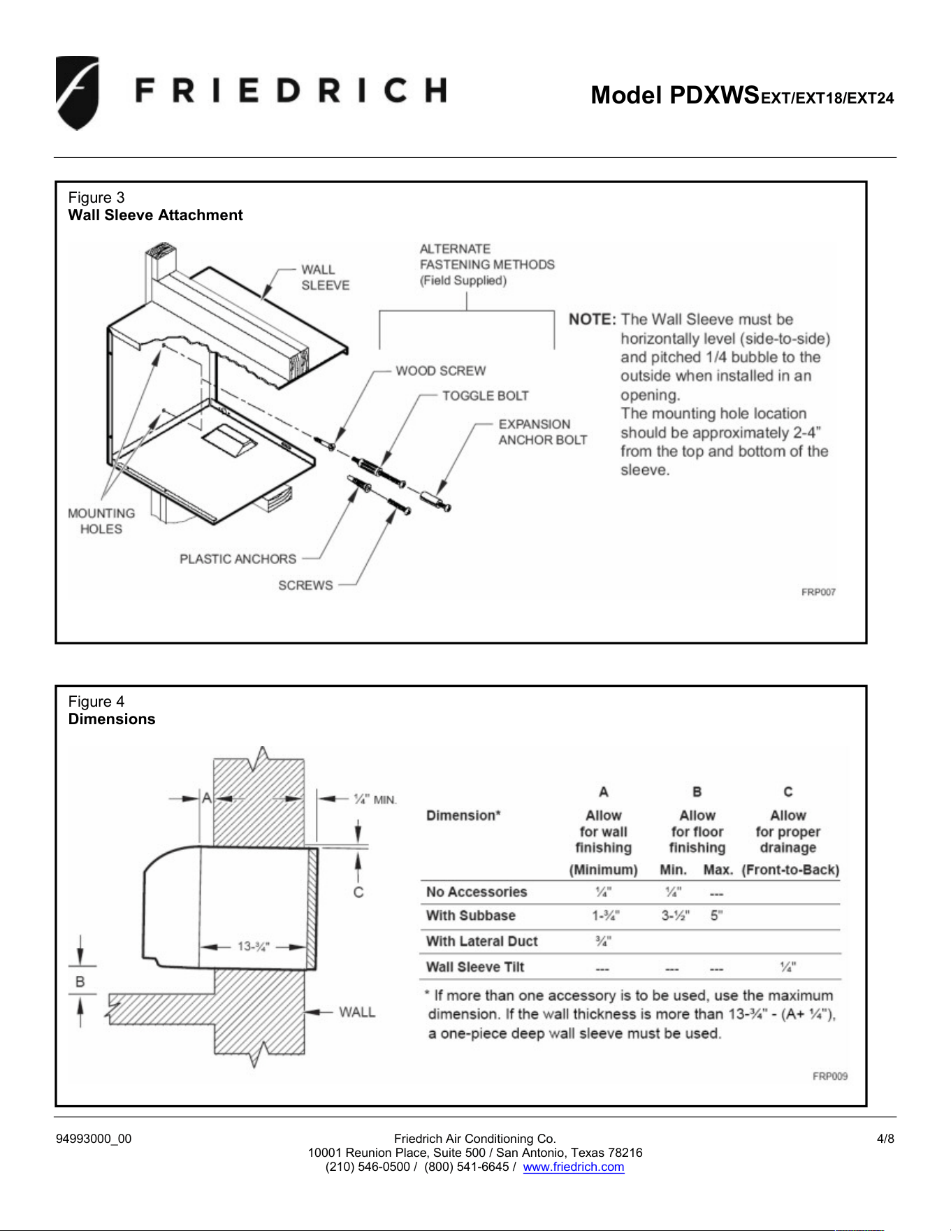
Figure 3
Wall Sleeve Attachment
Figure 4
Dimensions
Model PDXWSEXT/EXT18/EXT24
94993000_00 Friedrich Air Conditioning Co. 5/8
10001 Reunion Place, Suite 500 / San Antonio, Texas 78216
(210) 546-0500 / (800) 541-6645 / www.friedrich.com
Figure 5
Lintel Installation
Model PDXWSEXT/EXT18/EXT24
94993000_00 Friedrich Air Conditioning Co. 6/8
10001 Reunion Place, Suite 500 / San Antonio, Texas 78216
(210) 546-0500 / (800) 541-6645 / www.friedrich.com
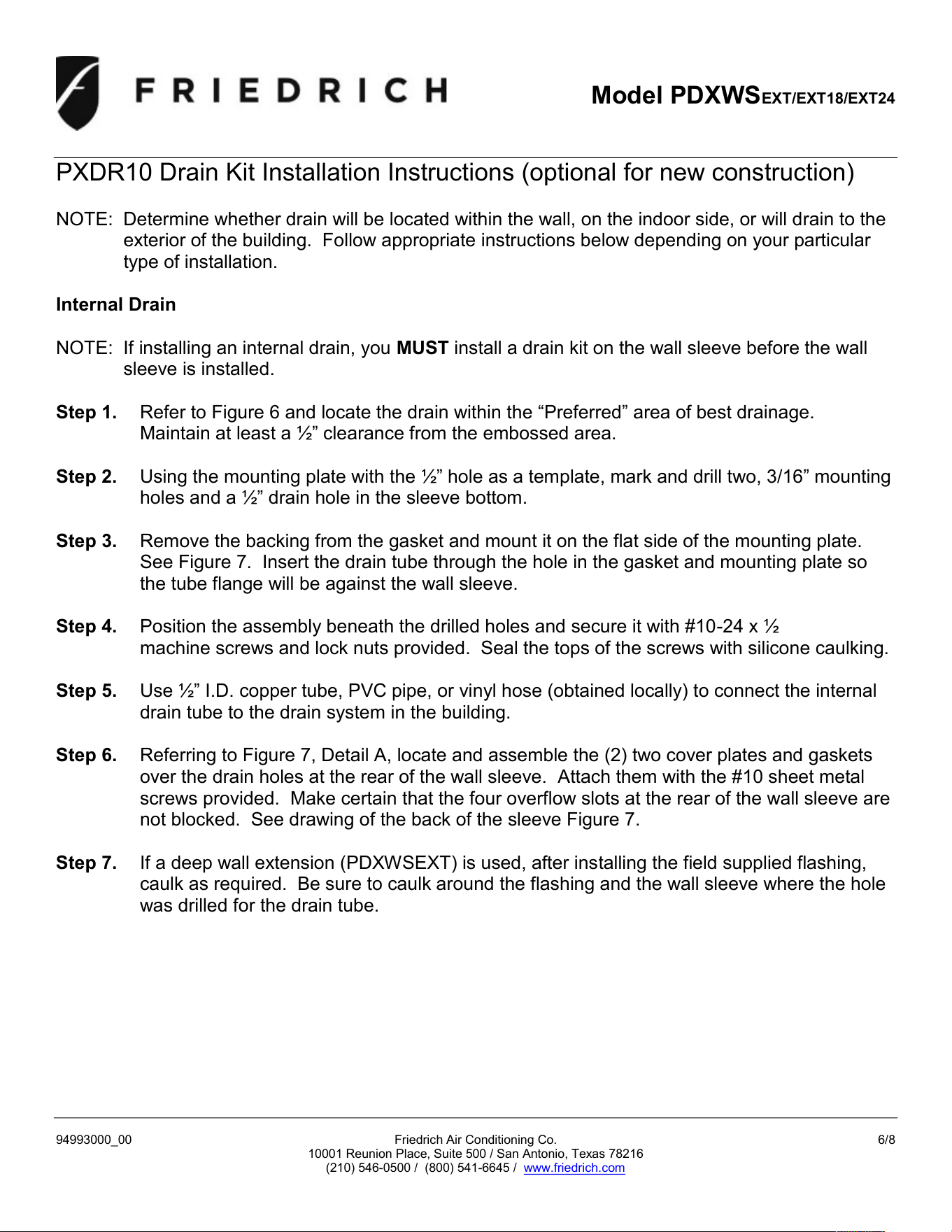
PXDR10 Drain Kit Installation Instructions (optional for new construction)
NOTE: Determine whether drain will be located within the wall, on the indoor side, or will drain to the
exterior of the building. Follow appropriate instructions below depending on your particular
type of installation.
Internal Drain
NOTE: If installing an internal drain, you MUST install a drain kit on the wall sleeve before the wall
sleeve is installed.
Step 1. Refer to Figure 6 and locate the drain within the “Preferred” area of best drainage.
Maintain at least a ” clearance from the embossed area.
Step 2. Using the mounting plate with the ” hole as a template, mark and drill two, 3/16” mounting
holes and a ” drain hole in the sleeve bottom.
Step 3. Remove the backing from the gasket and mount it on the flat side of the mounting plate.
See Figure 7. Insert the drain tube through the hole in the gasket and mounting plate so
the tube flange will be against the wall sleeve.
Step 4. Position the assembly beneath the drilled holes and secure it with #10-24 x ½
machine screws and lock nuts provided. Seal the tops of the screws with silicone caulking.
Step 5. Use ” I.D. copper tube, PVC pipe, or vinyl hose (obtained locally) to connect the internal
drain tube to the drain system in the building.
Step 6. Referring to Figure 7, Detail A, locate and assemble the (2) two cover plates and gaskets
over the drain holes at the rear of the wall sleeve. Attach them with the #10 sheet metal
screws provided. Make certain that the four overflow slots at the rear of the wall sleeve are
not blocked. See drawing of the back of the sleeve Figure 7.
Step 7. If a deep wall extension (PDXWSEXT) is used, after installing the field supplied flashing,
caulk as required. Be sure to caulk around the flashing and the wall sleeve where the hole
was drilled for the drain tube.
Model PDXWSEXT/EXT18/EXT24
94993000_00 Friedrich Air Conditioning Co. 7/8
10001 Reunion Place, Suite 500 / San Antonio, Texas 78216
(210) 546-0500 / (800) 541-6645 / www.friedrich.com
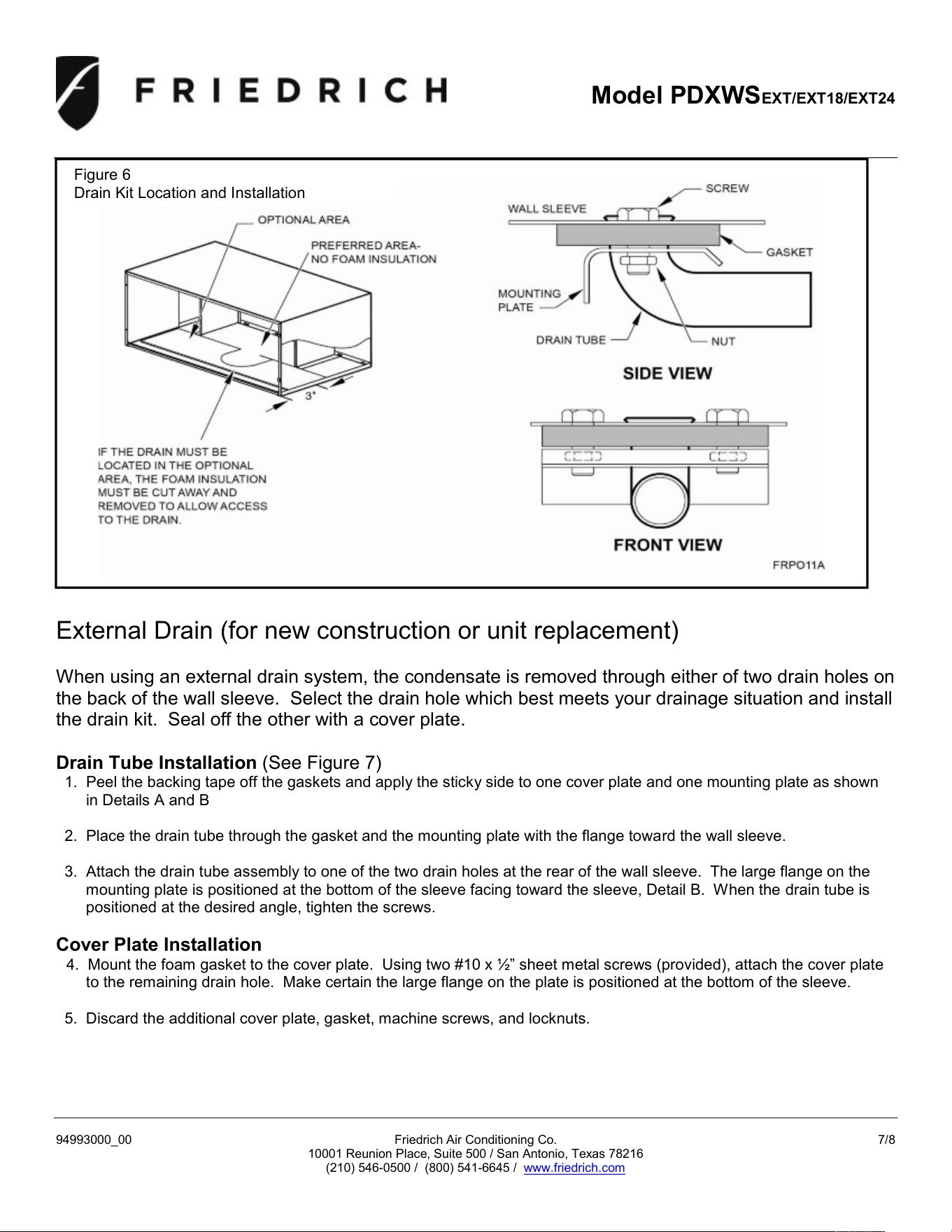
External Drain (for new construction or unit replacement)
When using an external drain system, the condensate is removed through either of two drain holes on
the back of the wall sleeve. Select the drain hole which best meets your drainage situation and install
the drain kit. Seal off the other with a cover plate.
Drain Tube Installation (See Figure 7)
1. Peel the backing tape off the gaskets and apply the sticky side to one cover plate and one mounting plate as shown
in Details A and B
2. Place the drain tube through the gasket and the mounting plate with the flange toward the wall sleeve.
3. Attach the drain tube assembly to one of the two drain holes at the rear of the wall sleeve. The large flange on the
mounting plate is positioned at the bottom of the sleeve facing toward the sleeve, Detail B. When the drain tube is
positioned at the desired angle, tighten the screws.
Cover Plate Installation
4. Mount the foam gasket to the cover plate. Using two #10 x ” sheet metal screws (provided), attach the cover plate
to the remaining drain hole. Make certain the large flange on the plate is positioned at the bottom of the sleeve.
5. Discard the additional cover plate, gasket, machine screws, and locknuts.
Figure 6
Drain Kit Location and Installation
Model PDXWSEXT/EXT18/EXT24
94993000_00 Friedrich Air Conditioning Co. 8/8
10001 Reunion Place, Suite 500 / San Antonio, Texas 78216
(210) 546-0500 / (800) 541-6645 / www.friedrich.com
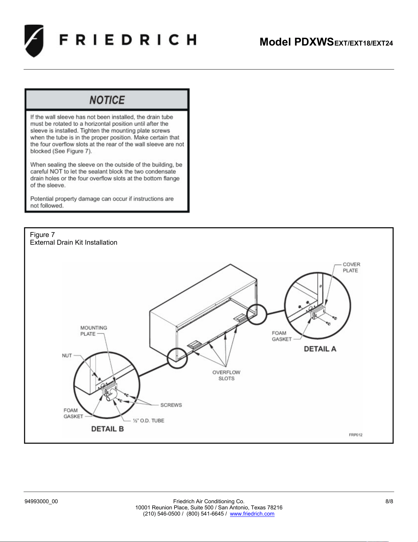
Figure 7
External Drain Kit Installation