Loading ...
Loading ...
Loading ...
920-087-04 (8-05)
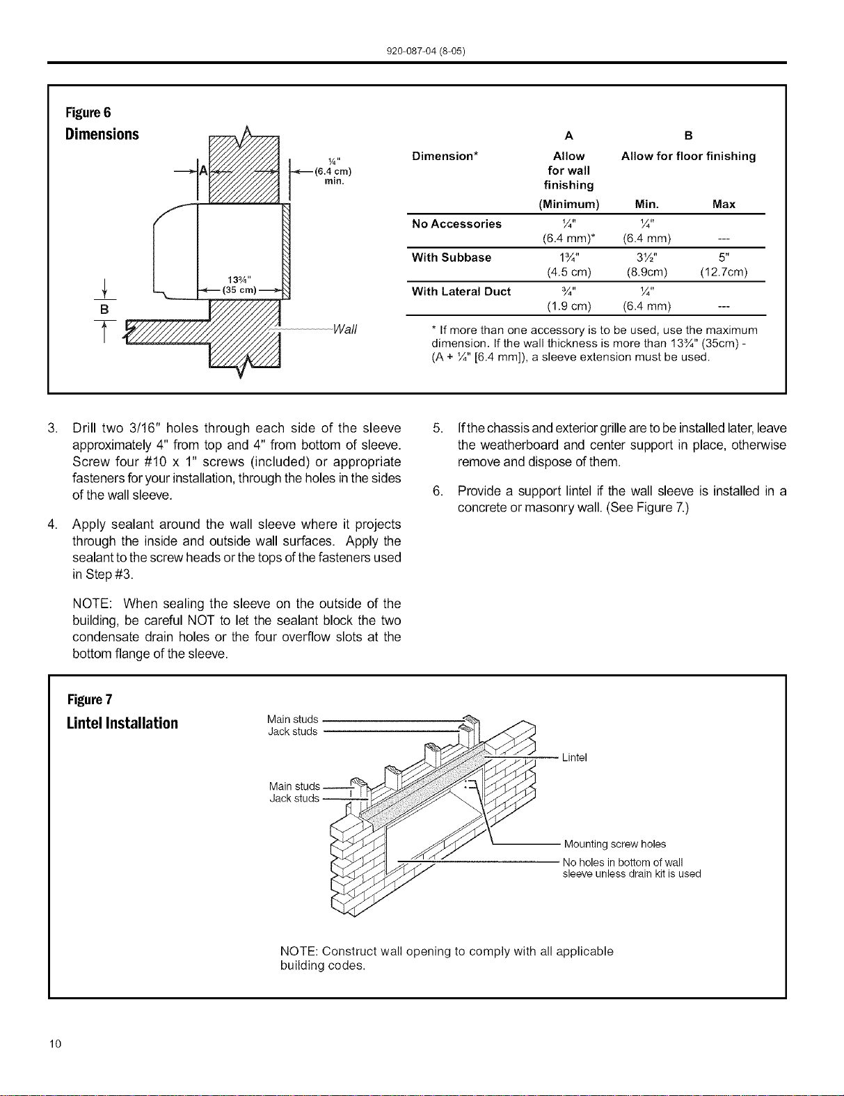
Figure6
Dimensions
B
T
(6.4 cm)
rain.
Wall
A B
Dimension* Allow Allow for floor finishing
for wall
finishing
(Minimum) Min. Max
No Accessories ¼" ¼"
(6.4 mm)* (6.4 mm) ---
With Su bbase 1¾" 3W' 5"
(4.5 cm) (8.9cm) (12.7cm)
With Lateral Duct ¾" ¼"
(1.9 cm) (6.4 mm) ---
* If more than one accessory is to be used, use the maximum
dimension. If the wall thickness is more than 13¾" (35cm) -
(A + ¼" [6.4 mm]), a sleeve extension must be used.
,
Drill two 3/16" holes through each side of the sleeve
approximately 4" from top and 4" from bottom of sleeve.
Screw four #10 x 1" screws (included) or appropriate
fasteners for your installation, through the holes in thesides
of the wall sleeve.
Apply sealant around the wall sleeve where it projects
through the inside and outside wall surfaces. Apply the
sealant to thescrew heads or the tops of thefasteners used
in Step #3.
NOTE: When sealing the sleeve on the outside of the
building, be careful NOT to let the sealant block the two
condensate drain holes or the four overflow slots at the
bottom flange of the sleeve.
Ifthechassis and exterior grilleareto be installed later,leave
the weatherboard and center support in place, otherwise
remove and dispose of them.
Provide a support lintel if the wall sleeve is installed in a
concrete or masonry wall. (See Figure 7.)
Figure7
LintelInstallation Mainstuds
Jack studs
Main
Lintel
Mounting screw holes
No holes in bottom of wall
sleeve unless drain kit is used
NOTE: Construct wall opening to comply with all applicable
building codes.
10
Loading ...
Loading ...
Loading ...