Loading ...
Loading ...
Loading ...
6
2 Hookup
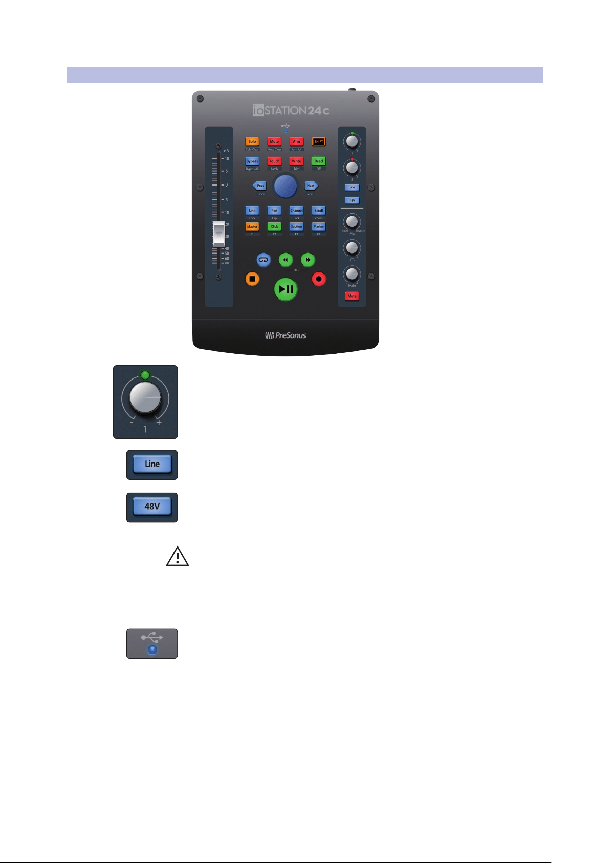
2.2 Top-Panel
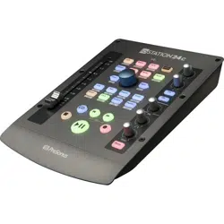
ioStation 24c Audio Interface and Production Controllers
Owner’s Manual
2.2 Top-Panel
Input Gain Controls. These knobs provide 80 dB of variable gain
for Mic and Instrument; 40 dB of range for Line (-20 to +20)
Clip Indicators. The red Clip LED will illuminate when your input signal reaches -0.5
dBFS. At this level, the signal will begin to overload the analog-to-digital converters
and exhibit signs of clipping. Use the gain controls to keep the signal below this level.
Line. Use the Line switch to toggle between instrument-level
and line-level sources. It will light up blue when selected; light off
indicates high-impedence instrument-level compatibility.
48V The ioStation 24c provides 48V phantom power for the microphone
inputs. Pressing the 48V button switches phantom power on and off
for all microphone inputs; the button will illuminate in blue when
phantom power is available on the microphone preamplifiers.
WARNING: Phantom power is only required for condenser microphones and can
severely damage some dynamic mics, especially ribbon mics. Therefore, switch
phantom power off when it is not required. Consult the user documentation
that came with your microphone before engaging phantom power.
XLR connector wiring for phantom power:
Pin 1 = GND Pin 2 = +48V Pin 3 = +48V
Sync LED. This light indicates if your ioStation 24c is in sync with your computer.
When no sync is available, this light will flash red.
Loading ...
Loading ...
Loading ...