Loading ...
Loading ...
Loading ...
ASSEMBLY
SPEED SELECT LEVER
1. Cut plastic tie securing speed select lever assembly to
the shifter bracket. (See Figure 7)
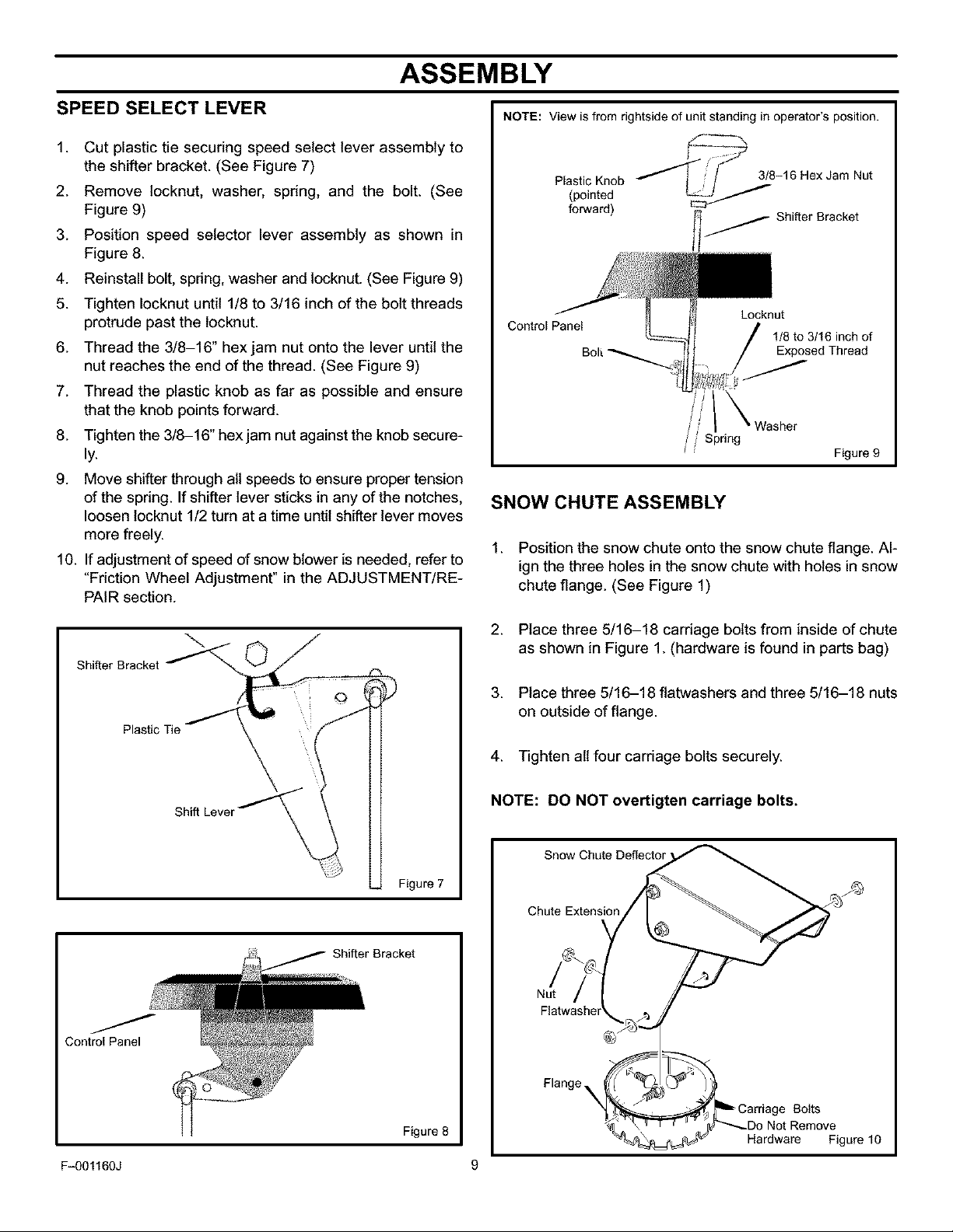
2. Remove locknut, washer, spring, and the bolt. (See
Figure 9)
3. Position speed selector lever assembly as shown in
Figure 8.
4. Reinstall bolt, spring, washer and locknut. (See Figure 9)
5. Tighten Iocknut until 1/8 to 3/16 inch of the bolt threads
protrude past the tocknut.
6. Thread the 3/8-16" hexjam nut onto the lever until the
nut reaches the end of the thread. (See Figure 9)
7. Thread the plastic knob as far as possible and ensure
that the knob points forward.
8. Tighten the 3/8-16" hex jam nut against the knob secure-
ly.
9. Move shifter through ait speeds to ensure proper tension
of the spring. If shifter lever sticks in any of the notches,
loosen locknut 1/2 turn at a time until shifter lever moves
more freely.
10. If adjustment of speed of snow blower is needed, refer to
"Friction Wheel Adjustment" in the ADJUSTMENT/RE-
PAIR section.
NOTE: View is from rightside of unit standing in operator's position.
stic oo
forward) Shifter Bracket
Control Panel
Locknut
1/8to3/16inchof
Exposed Thread
Figure 9
SNOW CHUTE ASSEMBLY
1. Position the snow chute onto the snow chute flange. Al-
ign the three holes in the snow chute with holes in snow
chute flange. (See Figure 1)
Shifter Bracket
Plastic Tie
Shift Lever
Figure 7
Shifter Bracket
Control Panel
Figure 8
2. Place three 5/16-18 carriage bolts from inside of chute
as shown in Figure 1. (hardware is found in parts bag)
3. Place three 5/16-18 flatwashers and three 5/16-18 nuts
on outside of flange.
4. Tighten all four carriage bolts securely.
NOTE: DO NOT overtigten carriage bolts.
Snow Chute Deflector
Chute Extension
Nut
Flange_
Bolts
Not Remove
Hardware Figure 10
Fq)O1160J 9
Loading ...
Loading ...
Loading ...