Loading ...
Loading ...
Loading ...
ASSEMBLY
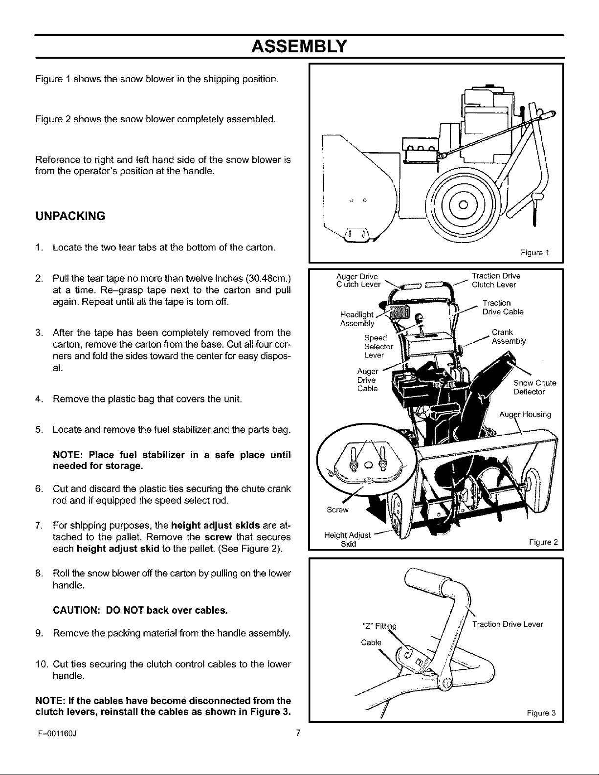
Figure 1 shows the snow blower in the shipping position.
Figure 2 shows the snow blower completely assembled.
Reference to right and left hand side of the snow blower is
from the operator's position at the handle.
UNPACKING
1. Locate the two tear tabs at the bottom of the carton.
2. Pull the tear tape no more than twelve inches (30.48cm.)
at a time. Re-grasp tape next to the carton and pull
again. Repeat until all the tape is torn off.
3. After the tape has been completely removed from the
carton, remove the carton from the base. Cut all four cor-
ners and fold the sides toward the center for easy dispos-
al.
4. Remove the plastic bag that covers the unit.
5. Locate and remove the fuel stabilizer and the parts bag.
NOTE: Place fuel stabilizer in a safe place until
needed for storage.
6. Cut and discard the plastic ties securing the chute crank
rod and if equipped the speed select rod.
7. For shipping purposes, the height adjust skids are at-
tached to the pallet. Remove the screw that secures
each height adjust skid to the pallet. (See Figure 2).
8. Roll the snow blower off the carton by pulling on the lower
handle.
CAUTION: DO NOT back over cables.
9. Remove the packing material from the handle assembly.
10. Cut ties securing the clutch control cables to the lower
handle.
NOTE: If the cables have become disconnected from the
clutch levers, reinstall the cables as shown in Figure 3.
Auger Drive
Clutch Lever
Headl
Assembly
Speed
Selector
Lever
Traction Drive
Traction
Drive Cable
Crank
Figure 1
Drive
Cable
Snow Chute
Deflector
_rHousing
Skid
Figure 2
"Z" Fit
Cable
Traction Drive Lever
Figure 3
Fq)01160J 7
Loading ...
Loading ...
Loading ...