
IMPORTANT: Read all instructions carefully before using this product.
Retain this owner’s manual for future reference.
The specifications of this product may vary from this photo, subject to
change without notice.
4158.1-120219
MyCloud Fitness App
Recumbent Bike


1
TABLE OF CONTENT
SERVICE ------------------------------------------------------------------------ 2
LABEL PLACEMENT --------------------------------------------------------- 3
IMPORTANT SAFETY GUIDELINES------------------------------------- 4
OVERVIEW DRAWING ------------------------------------------------------ 6
PARTS LIST --------------------------------------------------------------------- 7
HARDWARE & TOOLS PACK ---------------------------------------------- 9
ASSEMBLY ---------------------------------------------------------------------- 10
CONSOLE ---------------------------------------------------------------------- 21
ADJUSTMENTS ---------------------------------------------------------------- 24
TRANSPORTING-------------------------------------------------------------- 25
TROUBLE SHOOTING & MAINTENANCE ----------------------------- 26
WARRANTY -------------------------------------------------------------------- 27
PARTS REQUEST FORM --------------------------------------------------- 28

2
SERVICE
IMPORTANT: FOR NORTH AMERICA ONLY
For damaged or defective product, questions, replacement parts or any other service
support, please contact our customer service department by the below methods:
For The Best Service, please Email:
service@paradigmhw.com
Response Time: 1-2 Business Days
Emailing us with the information above will be the best method to receive a response during
peak business hours
Website:
www.paradigmhw.com
Toll-Free:
1-844-641-7921
(8:00 AM - 5:00 PM Pacific Standard Time, Monday thru Friday)
Response time may vary via calling
Please have the following information ready when requesting for service:
Your name
Phone number
Model number
Serial number
Part number
Proof of Purchase
For damaged or defective product please contact our customer service before returning to
the store.
Paradigm Health & Wellness, Inc.
1189 Jellick Ave.
City of Industry, CA 91748, USA
3
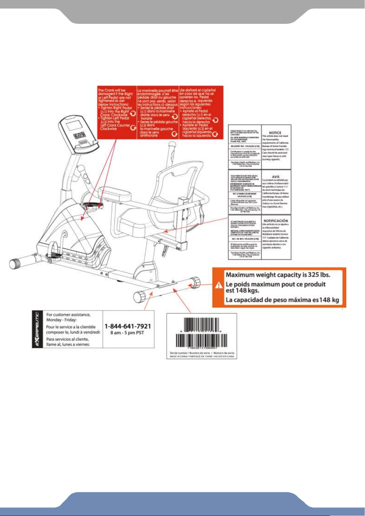
LABEL PLACEMENT

4
IMPORTANT SAFETY GUIDELINES
Read all instructions before using the equipment. When using the equipment, basic
precautions should always be followed. WARNING - To reduce the risk of injury to
persons, read and under the following:
1. Make sure your equipment is correctly assembled before you use it.
2. Be sure all screws, nuts, and bolts are tightened prior to use.
3. Before using this equipment, we recommend doing warm ups and stretching of the major muscle
groups.
4. Only one person should be using the equipment at a time.
5. Never operate this equipment if it is damaged, if it is not working properly, has been dropped, or
damaged. If a problem is encountered contact Customer Service before using the equipment
again.
6. Always use this equipment on a clear and level surface.
7. For household use only.
8. Do not use outdoors or near water.
9. Use this product only for its intended use as described in this manual. Do not use attachments not
recommended by the manufacturer.
10. Do not wear loose clothing when using the equipment.
11. Never drop or insert any object into any opening.
12. If at any time you feel faint, light-headed, or dizziness while operating the equipment, stop
exercising immediately. You should also stop exercising if you are experiencing pain or any
discomfort.
13. For any problems contact customer service. Servicing should be performed by an authorized
service representative. Our contact number is on the service page.
14. DO NOT pedal in reverse.
15. This product requires a minimum of 6 square feet of space for safe operation.
16. ASSEMBLE ALL HARDWARE IN THE ORDER THAT IS SHOWN IN THE ILLUSTRATIONS
17. Warning: - Risk of Personal Injury - Consult with your personal physician to see if this
exercise equipment is appropriate for you. This is especially important for people with pre-existing
health problems. Do not use this equipment without your physician's approval.
18. Warning: - Risk of Personal Injury – Do not allow children to use this machine.
19. Warning: - Risk of Personal Injury - Keep children under the age of 13 away from the
machine.
20. Warning: - Risk of Personal Injury – Keep body parts, hair, loose clothing, and jewelry
clear of all moving parts.
21. Warning: - Risk of Personal Injury - Do not attempt to service the unit yourself. Discontinue
use and contact customer service.
22. Warning: - To Reduce The Risk Of Personal Injury - Read And Understand All Read The
Instructions Before Using the Bike.

5
IMPORTANT SAFETY GUIDELINES
Talk to your Doctor before using the equipment if you have any of the following
conditions or ailments:
Pregnancy
Extreme obesity
Middle ear infection
Hiatus hernia or Ventral hernia
Glaucoma, retinal detachment or conjunctivitis
Use of anticoagulants including Aspirin in high doses.
Spinal injury, Cerebral Sclerosis, or acutely swollen joints
Heart or circulatory disorders for which you are being treated
High blood pressure, Hypertension, Recent stroke or Transient Ischemic attack
Bone weaknesses including Osteoporosis, Unhealed fractures, Modular pins, or surgically implanted
orthopedic supports.
Do not exceed the maximum rated weight (load):
The Maximum Weight Capacity for this product is 325lbs / 148kgs.
Retain this owner’s manual and keep the original purchase receipt
for future reference.
SAVE THESE GUIDELINES
6
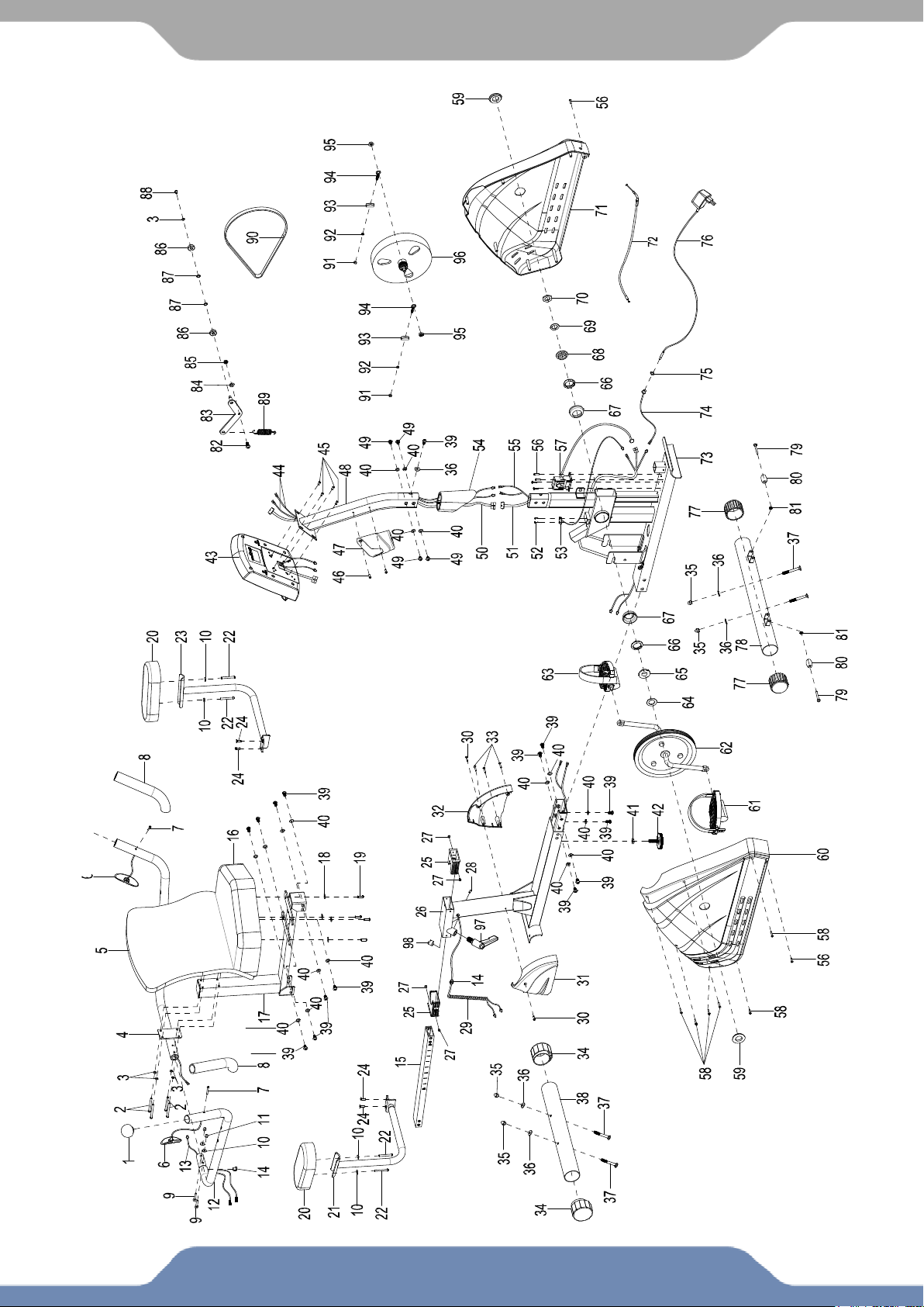
OVERVIEW DRAWING

7
PARTS LIST
No.
Description
Qty
No.
Description
Qty
1
Handrail End Cap Ø32x1.5
2
30
Phillips Self Tapping Screw
ST4.8x20
2
2
Hex Bolt M6x70
4
31
Right Decorate Cover Ø60
1
3
Flat Washer Ø6xØ12x1.0
5
32
Left Decorate Cover Ø60
1
4
Left Handrail Ø32x1.5x1085
1
33
Screw ST4.8x25
3
5
Backrest 465x465x135
1
34
Rear Stabilizer End Cap Ø60
2
6
Hand Pulse Sensor with Wire
L=1150 mm
2
35
Cap Nut M8
4
7
Screw ST4.2x30
2
36
Big Curve Washer Ø8xØ20x2.0
5
8
Handrail Foam Grip
Ø31xØ37x230
2
37
Carriage Bolt M8x70
4
9
Carriage Bolt M6x35
2
38
Rear Stabilizer Ø60x1.5x580
1
10
Big Curve Washer Ø6xØ16x1.5
6
39
Bolt M8x15
15
11
Cap Nut M6
2
40
Flat Washer Ø8xØ16x1.5
18
12
Right Handrail Ø32x1.5x929
1
41
Hexagon Nut M10xH5
1
13
Extension Hand Pulse Sensor
Wire L=200 mm
1
42
Adjustable Leveler M10
1
14
Wire Grommet Ø12.1
2
43
Console
1
15
Seat Sliding Tube 53x23x2
1
44
Extension Hand Pulse Sensor
Wire III L=650 mm
2
16
Seat 430x330x90
1
45
Hex Bolt M5x10
4
17
Back and Seat Support Bracket
53x23x2
1
46
Hex Bolt M5x15
2
18
Flat Washer Ø6xØ18x1.5
4
47
Bottle Holder
1
19
Hex Bolt M6x20
4
48
Front Post 70x30x1.5
1
20
Armrest 250x110x45
2
49
Hex Bolt M8x10
4
21
Right Handrail Support Tube
Ø25x1.5
1
50
Extension Sensor Wire I
L=600 mm
1
22
Hex Bolt M6x50
4
051
Extension Sensor Wire
L=600 mm
1
23
Left Handrail Support Tube
Ø25x1.5
1
052
Screw ST2.9x12
2
24
Hex Bolt M6x15
4
053
Sensor with Wire L=300 mm
1
25
Bushing
2
054
Front Post Cover
1
26
Rear Main Frame
1
055
Extension Hand Pulse Sensor
Wire II L=1200 mm
1
29
Extension Hand Pulse Sensor
Wire I L=1300 mm
1
056
Phillips Self Tapping Screw
ST4.2x20
6

8
PARTS LIST
No.
Description
Qty
No.
Description
Qty
58
Screw ST4.2x25
6
70
Hexagon Nut 7/8”
1
59
Cover Cap Ø40xØ25x10
2
71
Left Cover 672x83x448
1
60
Right Cover 672x79x448
1
72
Magnetic Brake Cable L=280
mm
1
61
Right Foot Pedal (YH-63X)
1
73
Front Main Frame 80x40x2
1
62
Crank with Belt Pulley Ø240
1
74
Power Supply Cable L=300 mm
1
63
Left Foot Pedal (YH-63X)
1
75
Hex Nut 1/2”
1
64
Washer Ø24xØ40x3.0
1
76
Adapter L=2000 mm
1
65
Bearing Nut I 15/16"
1
77
Front Stabilizer End Cap Ø60
2
66
Ball Bearing
2
78
Front Stabilizer Ø60x1.5x580
1
67
Bearing Cup
2
79
Hex Bolt M6x45
2
68
Bearing Nut II 7/8"
1
80
Transport Wheel Ø23xØ6x32
2
69
Washer Ø23xØ34.5x2.5
1
81
Nylon Nut M6
2
70
Hexagon Nut 7/8”
1
82
Hex Bolt M8x20
1
71
Left Cover 672x83x448
1
83
Idler Arm
1
72
Magnetic Brake Cable L=280 mm
1
84
Big Washer Ø8xØ20x2
1
73
Front Main Frame 80x40x2
1
85
Nylon Nut M8
1
74
Power Supply Cable L=300 mm
1
86
Bearing 6000-2Z
2
58
Screw ST4.2x25
6
87
Flat Washer Ø10xØ14x1.0
2
59
Cover Cap Ø40xØ25x10
2
88
Hex Bolt M6x10
1
60
Right Cover 672x79x448
1
89
Spring Ø17x80xØ2.5
1
61
Right Foot Pedal (YH-63X)
1
90
Belt PJ360 J6
1
62
Crank with Belt Pulley Ø240
1
91
Nut M6
2
63
Left Foot Pedal (YH-63X)
1
92
Spring Washer Ø6
2
64
Flat Washer Ø24xØ40x3.0
1
93
Tension Bracket
2
65
Bearing Nut I 15/16"
1
94
Adjustable Bolt M6x36
2
66
Ball Bearing
2
95
Nut M10x1.0x6
2
67
Bearing Cup
2
96
Flywheel Ø230
1
68
Bearing Nut II 7/8"
1
97
L Shape Knob M6x1.5
1
69
Flat Washer Ø23xØ34.5x2.5
1
9
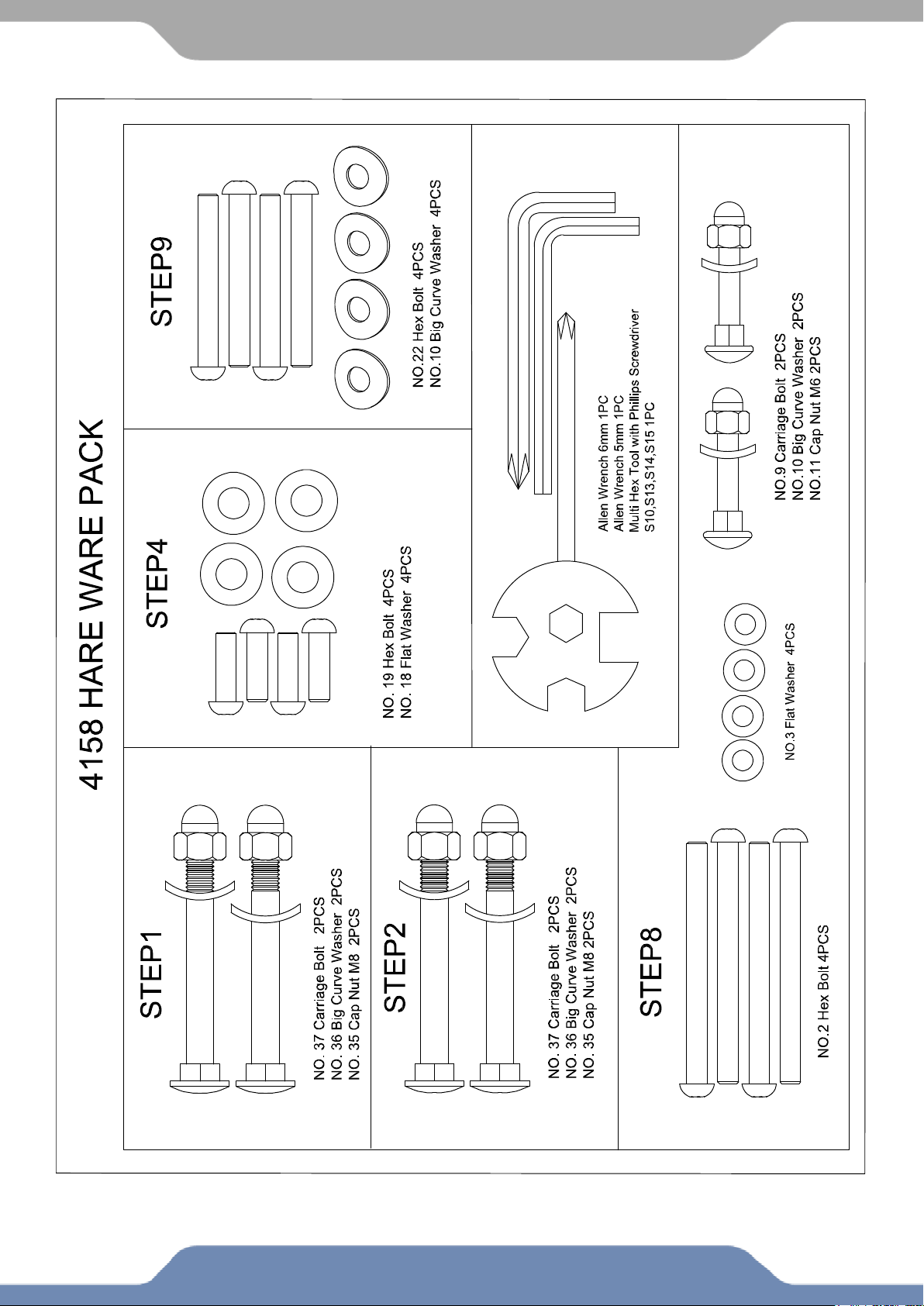
HARDWARE & TOOLS PACK
10
ASSEMBLY
Multi Hex Tool with Phillips Screwdriver
S10, S13, S14, S15 1PC
Tool:
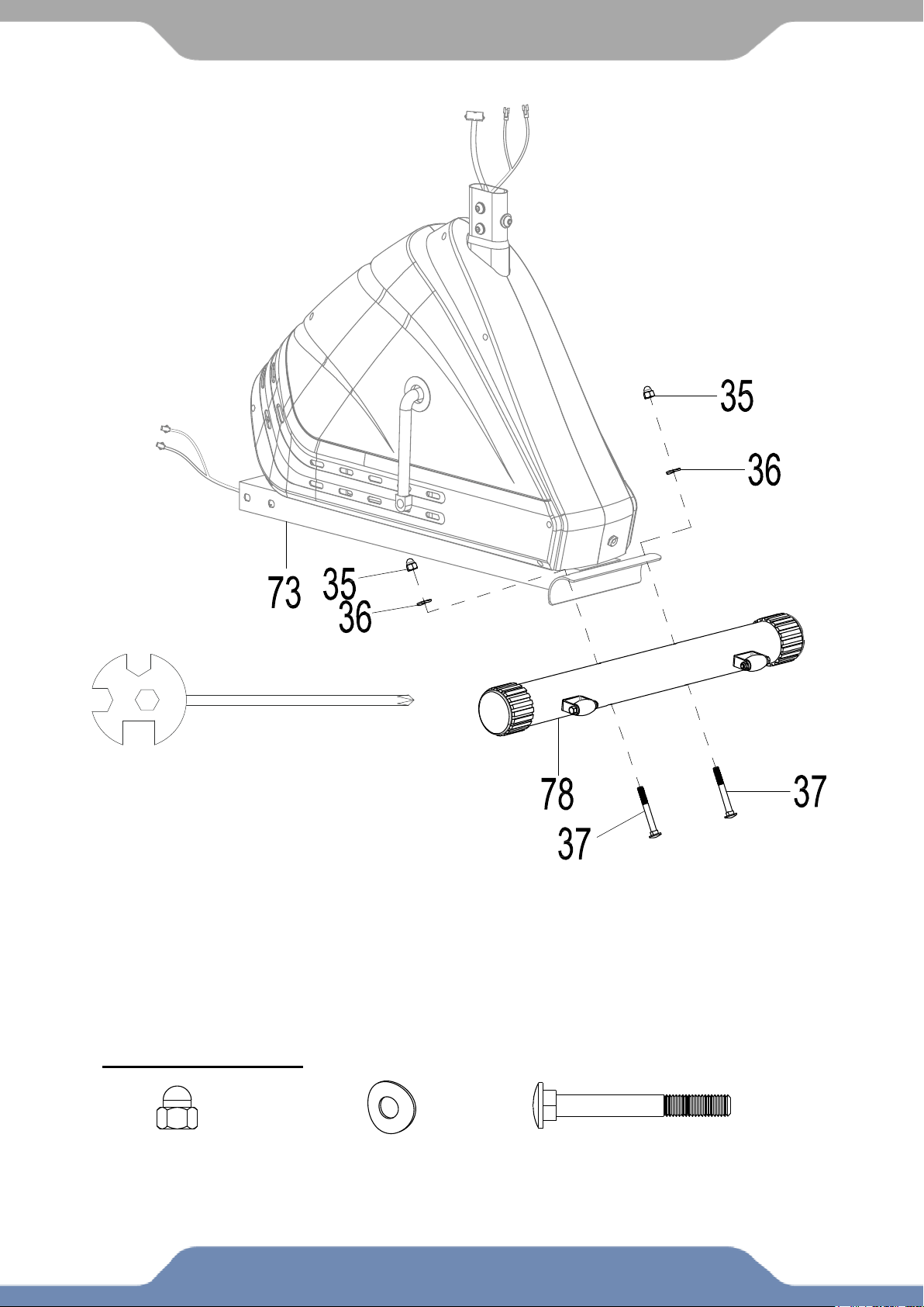
STEP 1
1a. Front Stabilizer Installation: Lift up the Front Main Frame (73), and align the Front
Stabilizer (78) onto the front curve of the Front Main Frame (73). Insert two Bolts (37)
into the Front Stabilizer (78), then on the threaded ends of the Bolts (37) attach two Big
Curve Washers (36) and two Cap Nuts (35). Hold the Front Stabilizer (78) to the Front
Main Frame (73) and use the Multi Hex Tool with Phillips Screwdriver provided to
tighten the Cap Nuts (35) until secure.
HARDWARE PACK:
(35) Cap Nut
2 PCS
(36) Big Curve Washer
2 PCS
(37) Carriage Bolt
2 PCS
11
ASSEMBLY
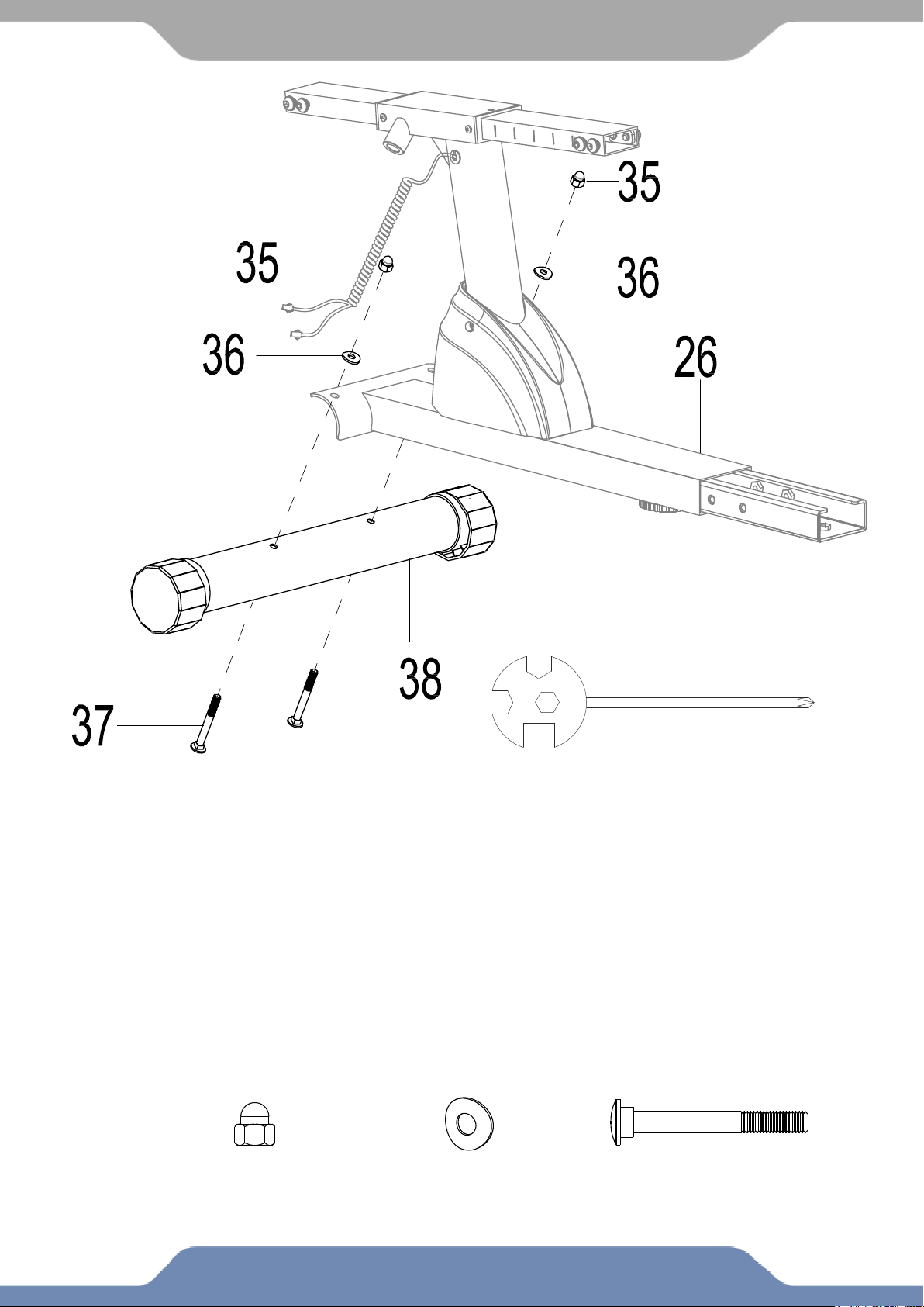
STEP 2
2a. Installing the Rear Stabilizer: Lift up the Rear Main Frame (26), and align the Rear Stabilizer
(38) onto the rear curve of the Rear Main Frame (26). Insert two Bolts (37) into the Rear
Stabilizer (38), then on the threaded ends of the Bolts (37) attach two Big Curve Washers (36)
and two Cap Nuts (35). Hold the Rear Stabilizer (38) to the Rear Main Frame (26) and use the
Multi Hex Tool with Phillips Screwdriver provided to tighten the Cap Nuts (35) until secure.
Hardware:
(35) Cap Nut
2 PCS
(36) Big Curve Washer
2 PCS
(37) Carriage Bolt
2 PCS
Tool:
Multi Hex Tool with Phillips Screwdriver
S10, S13, S14, S15 1PC
12
ASSEMBLY
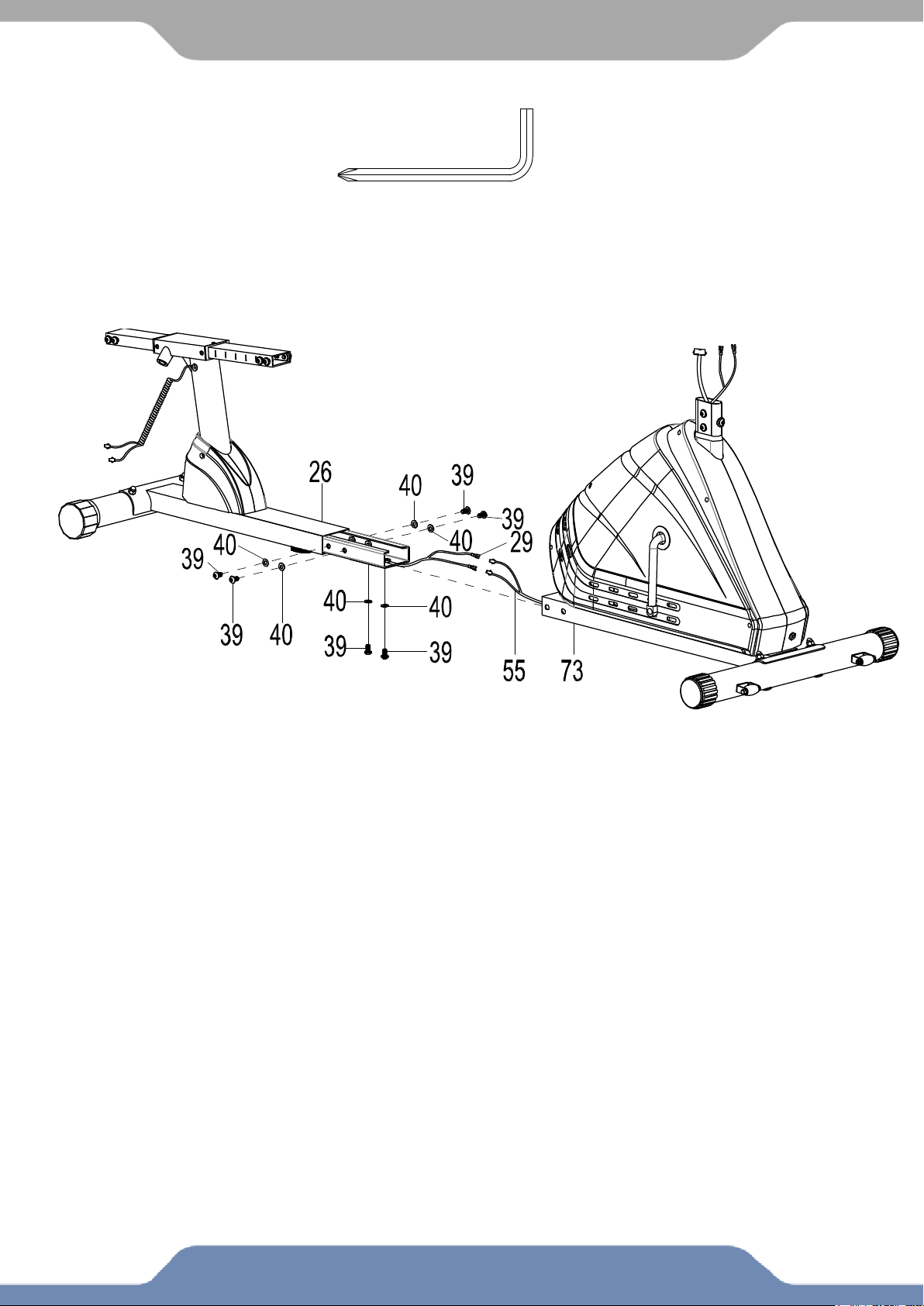
STEP 3
3a. Hardware Removal: Use the 6mm Allen Wrench with Phillips Screwdriver provided to
remove the six Hex Bolts (39) and the six Flat Washers (40) from the Rear Main Frame (26).
3b. Installing the Main Frame: Connect the Extension Hand Pulse Sensor Wire I (29) from the
Rear Main Frame (26) with the Extension Hand Pulse Sensor Wire II (55) from the Front Main
Frame (73). Insert the Rear Main Frame (26) into Front Main Frame (73). Make sure the wires
stay connected and are not pinched. Re-insert the six Hex Bolts (39) and the six Flat Washers (40)
into the Front Main Frame (73). Tighten the six Hex Bolts (39) using the 6mm Allen Wrench with
Phillips Screwdriver Provided.
Tool:
6mm Allen Wrench with
Phillips Screwdriver
1 PC
13
ASSEMBLY
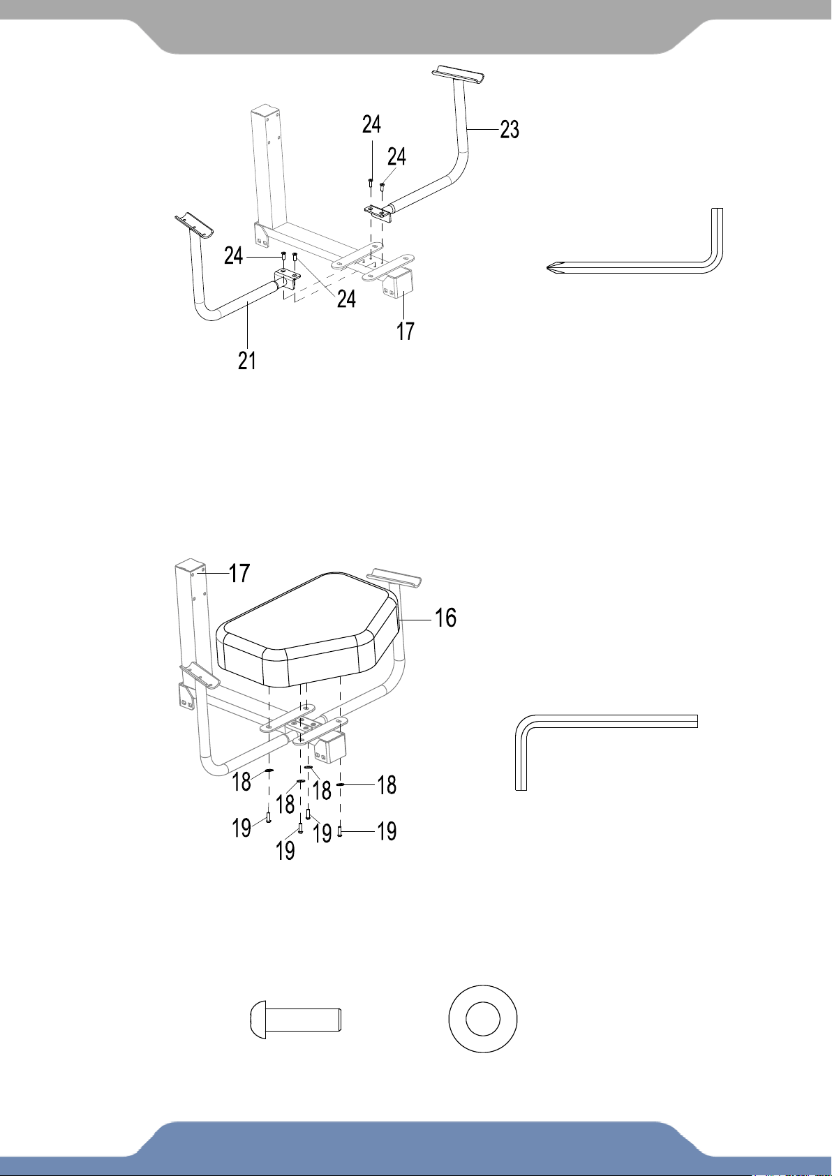
STEP 4
4.1 Hardware Removal: Use the Multi Hex Tool with Phillips Screwdriver to remove the four
Hex Bolts (24) from the Back and Seat Support Bracket (17).
4.2 Installing the Right/Left Handrail Support Tubes: Align the holes of the Right Handrail
Support Tube (21) and the Back and Seat Support Bracket (17). Re-insert two Hex Bolts (24)
into the Right Handrail Support Tube (21) and use the Multi Hex Tool with Phillips Screwdriver
provided to tighten until secure. Repeat the same assembly steps for the Left Handrail Support
Tube (23).
4.3 Installing the Seat: Align the holes of the Seat (16) and the Back and Seat Support
Bracket (17). Insert the four Hex Bolts (19) with four Flat Washers (18) into the Back and
Seat Support Bracket (17). Use the 5mm Allen Wrench provided to tighten the four Flat
Washers (18) and four Hex Bolts (19) until secure.
Tool:
6mm Allen Wrench with
Phillips Screwdriver
1PC
5mm Allen Wrench
1PC
Tool:
Hardware:
(19) Hex Bolt
4 PCS
(18) Flat Washer
4 PCS
14
ASSEMBLY
STEP 5
5.1 Hardware Removal: Use the 6mm Allen Wrench with Phillips Screwdriver to
remove the eight Hex Bolts (39) and the eight Flat Washers (40) from the Seat Sliding
Tube (15). Retain the hardware for Back and Seat Support Bracket installation. 5.2.
5.2 Installing the Back/Seat Support Bracket : Attach the Back and Seat Support
Bracket (17) onto the Seat Sliding Tube (15) using the eight Hex Bolts (39) and the eight
Flat Washers (40) that were previously removed. Tighten the Hex Bolts (39) with the 6mm
Allen Wrench with Phillips Screwdriver provided.
5.3 Installing the L-Shape Knob: Install the L-Shape Knob (97) and tighten it by
turning in a clockwise direction.
Tool:
6mm Allen Wrench with
Phillips Screwdriver
1PC
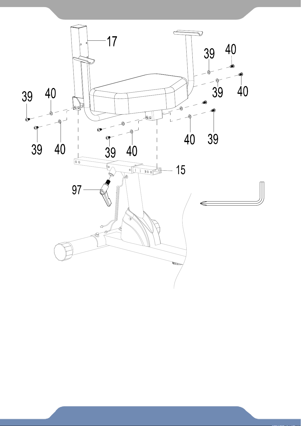
15
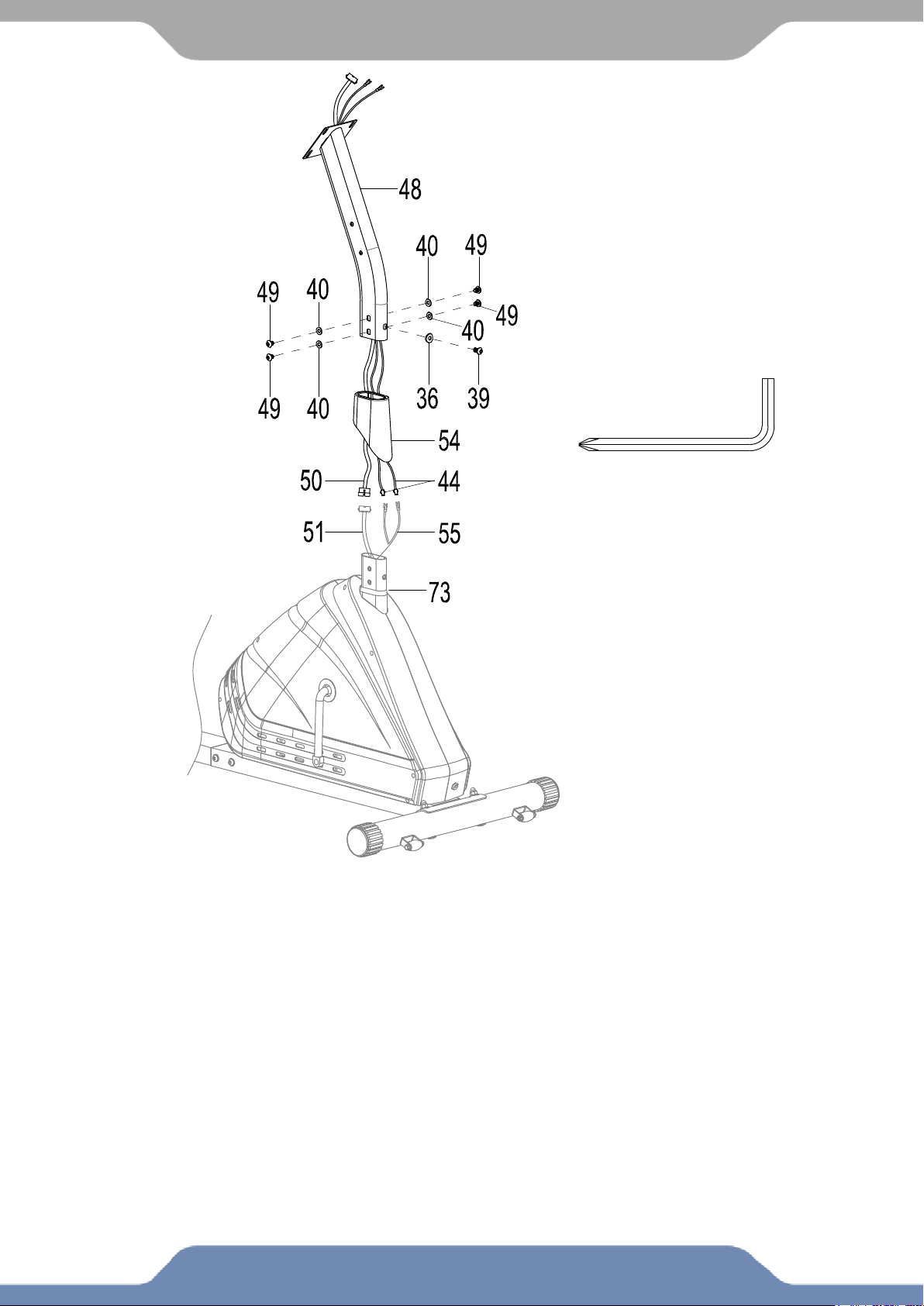
ASSEMBLY
STEP 6
6.1 Hardware Removal: Use the 6mm Allen Wrench with Phillips Screwdriver provided to
remove the four Flat Washers (40), four Hex Bolts (49), one Hex Bolt (39), and one Big Curve
Washer (36) from the tube of the Front Main Frame (73).
6.2 Installing the Front Post Cover: Slide the Front Post Cover (54) up on to the Front Post (48)
and keep it there. Connect the Extension Sensor Wire (51) to the Extension Sensor Wire I (50).
Connect the Extension Hand Pulse Sensor Wire II (55) to the Extension Hand Pulse Sensor
Wire III (44); make sure the wires are not pinched and stay connected. Place the Front Post (48)
onto the Front Main Frame (73).
6.3 Installing the Front Post: Insert the Front Post (48) onto the tube of the Front Main Frame
(73). Reinstall the previously removed hardware: four Flat Washers (40), four Hex Bolts (49), one
Hex Bolt (39), and one Big Curve Washer (36) and securely tighten the bolts using the 6mm
Allen Wrench with Phillips Screwdriver provided. Slide the Front Post Cover (54) down to cover the
hardware.
Tool:
6mm Allen Wrench with
Phillips Screwdriver
1PC
16
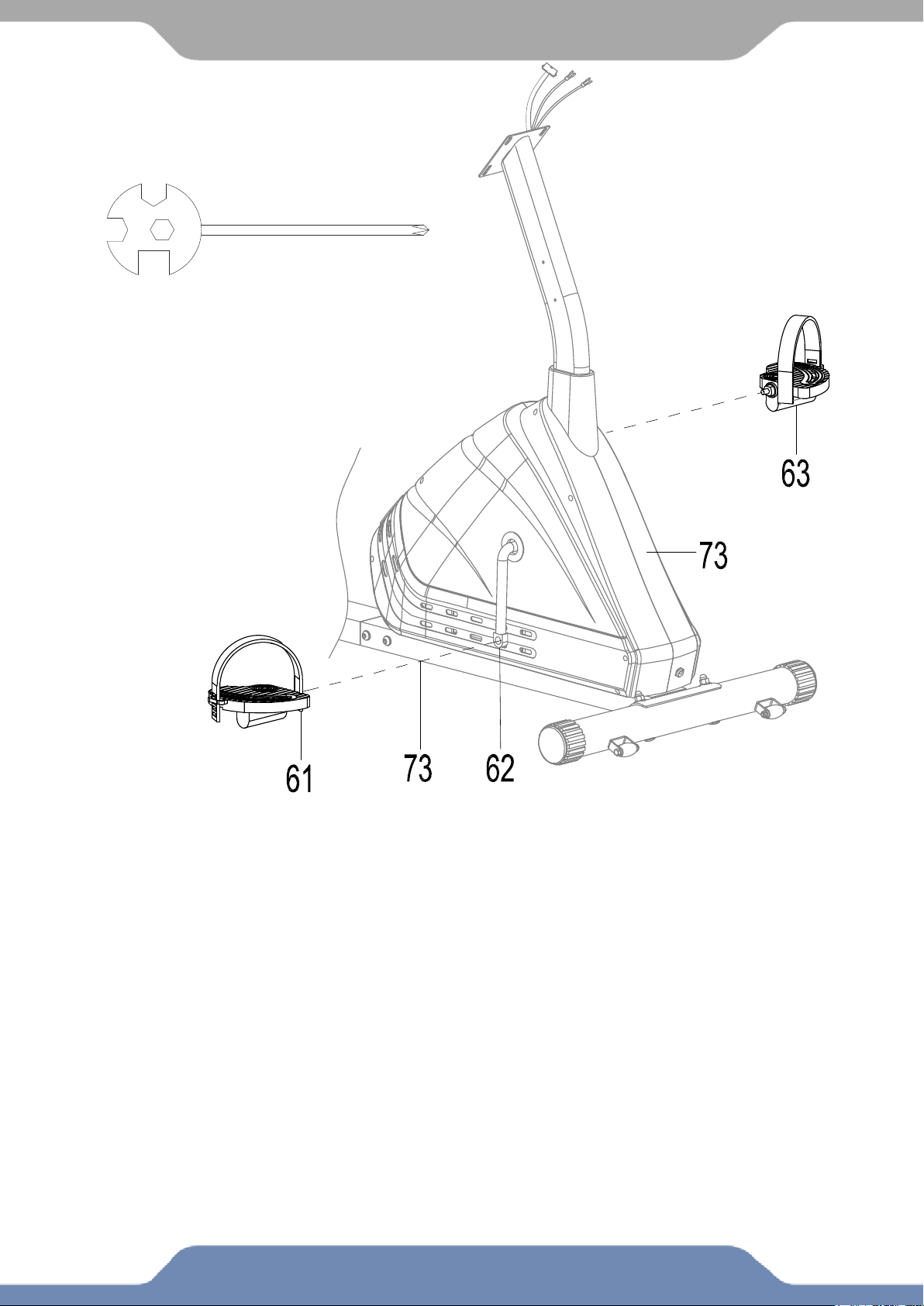
ASSEMBLY
NOTE: The Cranks, Pedal Shafts, and Foot Pedals are marked “R” for Right and “L” for Left.
STEP 7
7.1 Installing the Left and Right Foot Pedals:
Insert the Left Foot Pedal (63) into the threaded hole in the left side of the Crank (62). Turn
the Left Foot Pedal (63) by hand in a counter-clockwise direction until snug.
Note: DO NOT turn the pedal shaft in the clockwise direction, doing so will strip the
threads.
Tighten the Left Foot Pedal (63) using the Multi Hex Tool with Phillips Screwdriver
provided.
Insert the Right Foot Pedal (61) into the threaded hole in the right side of the Crank (62).
Turn the Right Foot Pedal (61) by hand in a clockwise direction until snug. Tighten the
Right Foot Pedal (61) with the Multi Hex Tool with Phillips Screwdriver provided
Tool:
Multi Hex Tool with Phillips Screwdriver
S10, S13, S14, S15 1PC
17
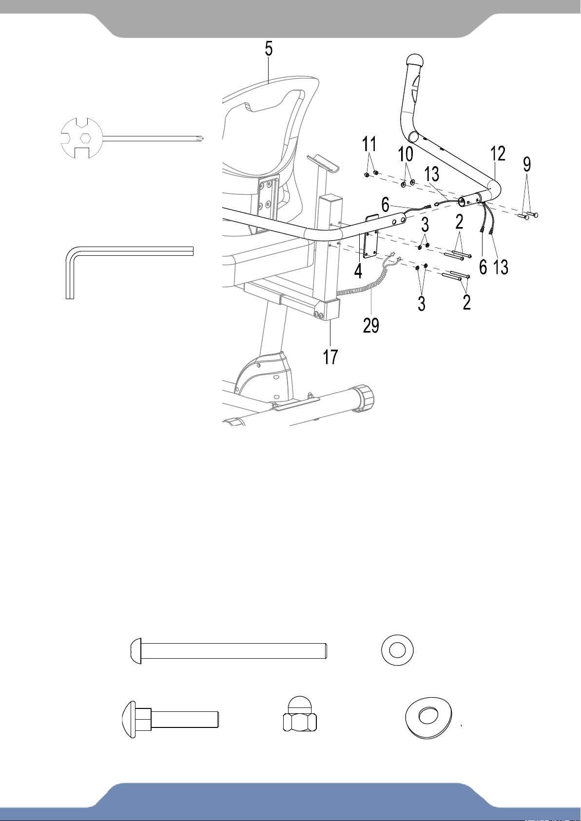
ASSEMBLY
STEP 8
8.1 Installing the Backrest: Attach the Backrest (5) and Left Handrail (4) onto the Back and
Seat Support Bracket (17), using four Hex Bolts (2) and four Flat Washers (3). Tighten the Hex
Bolts (2) using the 5mm Allen Wrench provided.
8.2 Connecting the Wires: Connect the Hand Pulse Sensor Wire (6) from the Left Handrail (4)
to the Extension Hand Pulse Sensor Wire (13) from the Right Handrail (12). Insert the Right
Handrail (12) into the Left Handrail (4) being careful not to pinch the wires. Secure the Left
Handrail (4) and Right Handrail (12) using two Carriage Bolts (9), two Big Curve Washer (10),
and two Cap Nuts (11). Tighten the Cap Nuts (11) using the Multi Hex Tool with Phillips
Screwdriver provided.
8.3 Connecting the Pulse Wire to the Frame: Connect the Extension Hand Pulse Sensor Wire
I (29) to the Hand Pulse Sensor Wire (6) and Extension Hand Pulse Sensor Wire (13).
Hardware:
(2) Hex Bolt
4 PCS
(9) Carriage Bolt
2 PCS
(10) Big Curve Washer
2 PCS
(11) Cap Nut
2 PCS
(3) Flat Washer
4 PCS
Tool:
Multi Hex Tool with
Phillips Screwdriver
S10, S13, S14, S15 1PC
5mm Allen Wrench
1PC
18
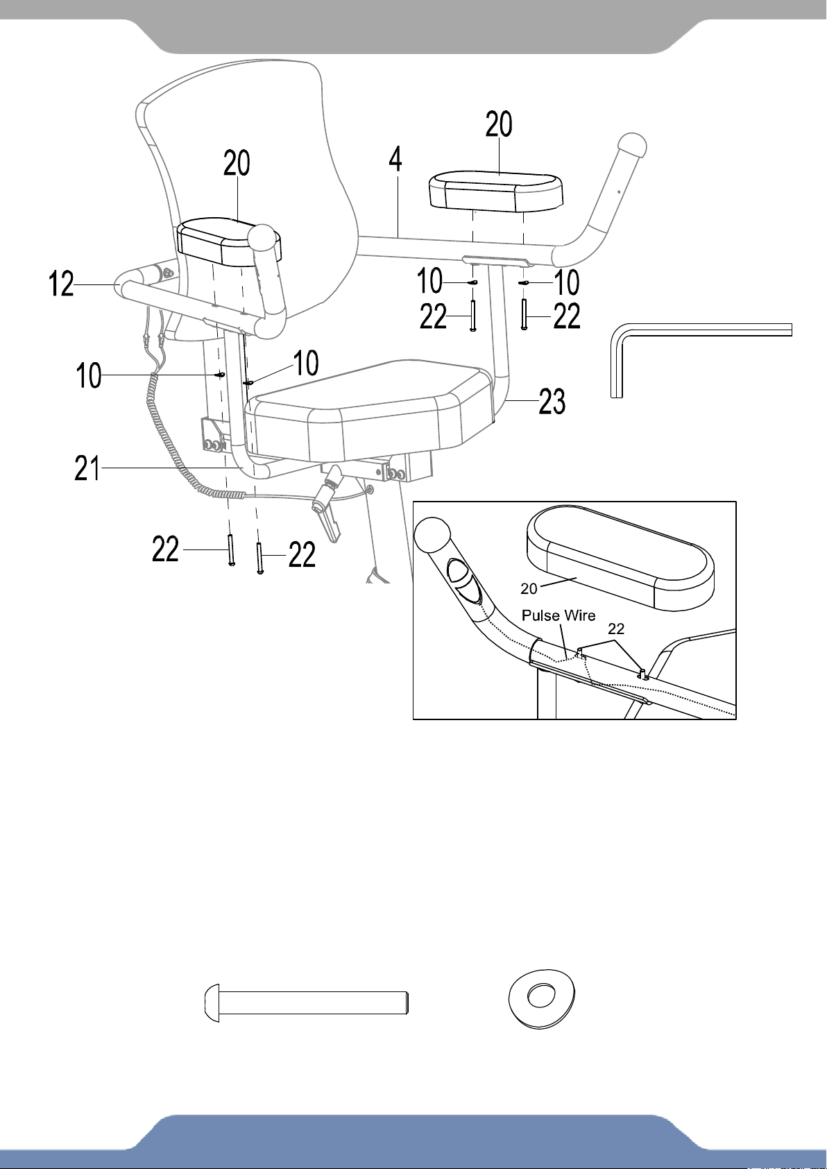
ASSEMBLY
STEP 9
Note: To prevent damaging the PULSE WIRE in the frame, make sure it is NOT pushed out when
inserting the Hex Bolts (35). See Fig. A
9.1 Installing the Armrest: Align the holes of the Armrest (20), the Right Handrail (12), and
the Right Hand Support Tube (21). Fasten the three parts together with two Hex Bolts (22)
and two Big Curve Washers (10). Use the 5mm Allen Wrench provided to tighten the two
Hex Bolts (22) and two Big Curve Washers (10) until firm and secure.
Repeat the step above for the second Armrest (20), the Left Handrail (4), and the Left
Handrail Support Tube (23).
5mm Allen Wrench
1PC
Tool:
Hardware:
(22) Hex Bolt
4 PCS
(10) Big Curve Washer
4 PCS
Fig. A
19
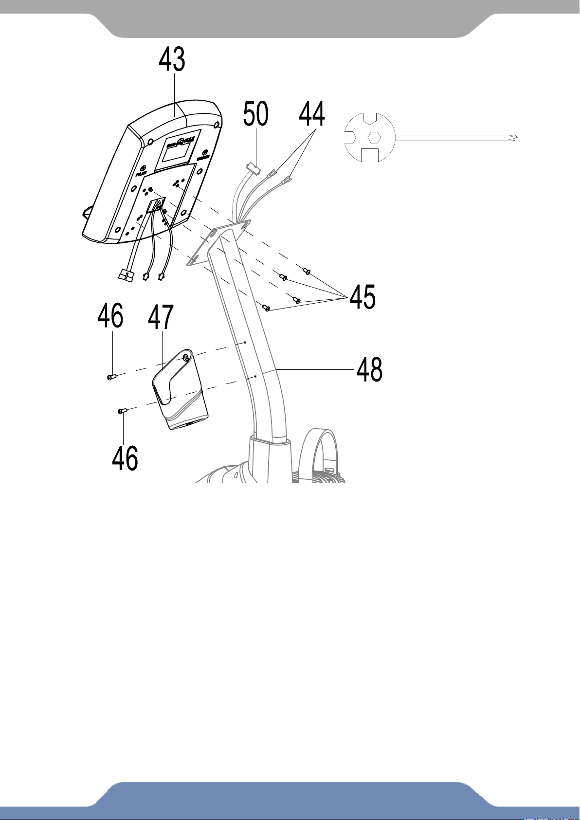
ASSEMBLY
STEP 10
10.1 Hardware Removal: Use the Multi Hex Tool with Phillips Screwdriver provided to remove
the four Hex Bolts (45) from the back of the Console (43). Use the Multi Hex Tool with Phillips
Screwdriver to remove the two Hex Bolts (46) from the right side of the Front Post (48)
10.2 Installing the Console: Connect the Extension Hand Pulse Sensor Wires III (44) and
Extension Sensor Wire I (50) to the wires at the rear of the Console (43). Carefully tuck the wires
into the Front Post (48). Attach the Console (43) onto the Front Post (48) with the four Hex Bolts
(45) that were previously removed. Tighten the Hex Bolts (45) using the Multi Hex Tool with
Phillips Screwdriver provided.
10.3 Installing the Bottle Holder: Attach the Bottle Holder (47) onto the Front Post (48) with two
Hex Bolts (46) that were previously removed. Tighten the bolts with the Multi Hex Tool with
Phillips Screwdriver provided.
Tool:
Multi Hex Tool with
Phillips Screwdriver
S10, S13, S14, S15 1PC
20
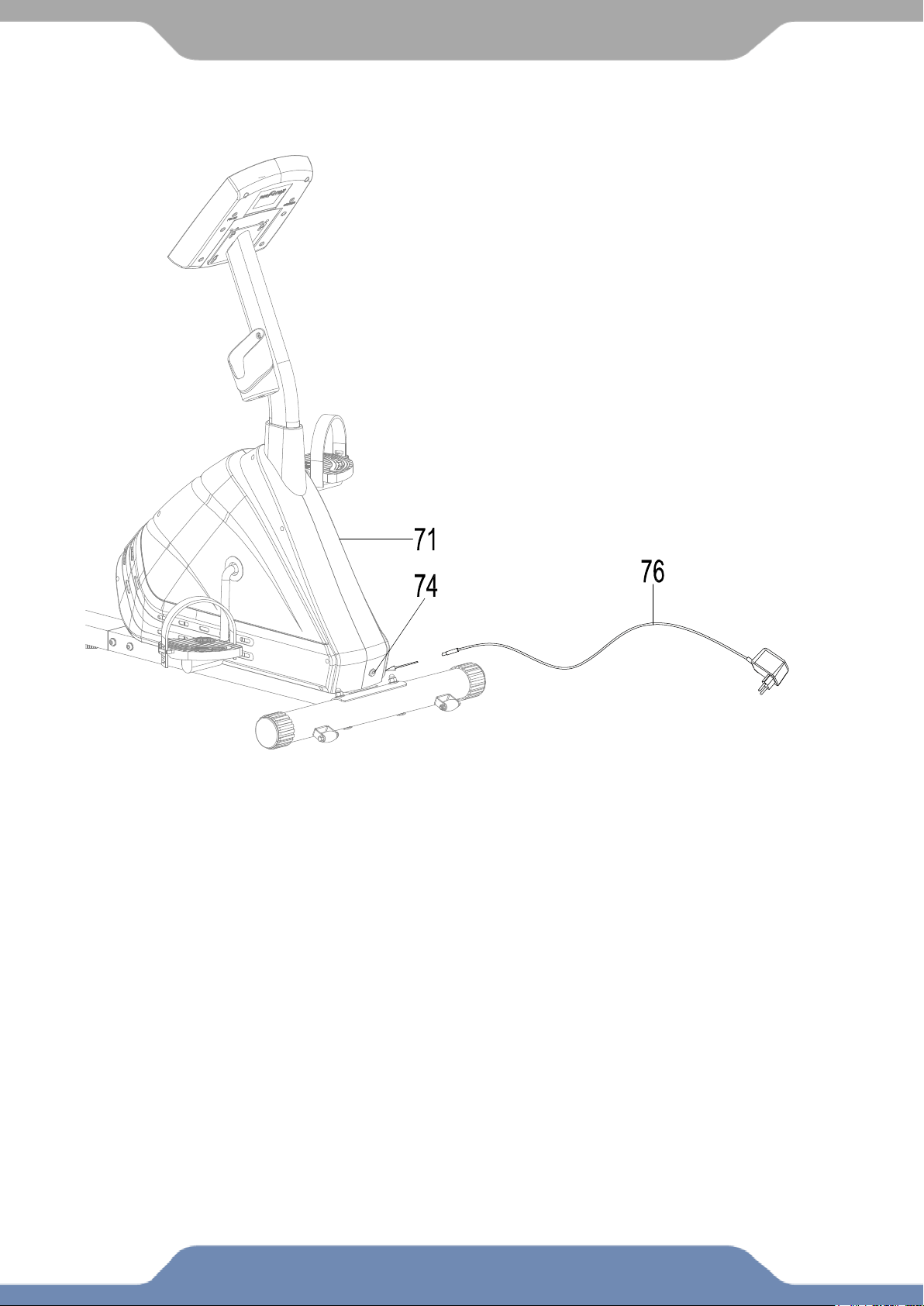
ASSEMBLY
STEP 11
11.1 Installing Adapter: Plug one end of the Adapter (76) into the power jack of the Power
Supply Cable (74) on the Left Cover (71). Before plugging in, make sure to carefully check the
specifications on the Adapter (76). Plug the other end of the Adapter (76) into the electrical wall
outlet.
Note: This bike can only be powered by a power adapter that is plugged into a wall outlet.
21
CONSOLE
Console Buttons:
START/STOP BUTTON:
1. Starts and Pauses a workout.
2. Holding the button for 3 seconds will reset the
console for a new workout.
UP & DOWN BUTTON:
1. Press to Increase or decrease the value of the
selected workout parameter when setting a
workout goal: TIME, DISTANCE, CALORIES.
2. Pressing during a workout will increase the
resistance load.
3. Pressing at the main screen will to
navigate through the training program modes
(Manual, Pre-set Programs, or User Program).
4. Press and hold both buttons at the main screen to change units from MILES to KM.
ENTER BUTTON:
1. Press to select the Goal option (TIME, DISTANCE, CALORIES) prior to starting a
workout.
RECOVERY BUTTON:
1. Press to enter into Recovery function when Console has the heart rate value.
2. The Recovery Scale is a range of F1 – F6, F1 signifies great fitness, and F6 signifies poor
fitness.
MODE BUTTON:
1. Press to switch displayed workout values RPM to SPEED, ODO to DIST, and WATT to
Calories during workout resistance during exercise.
ENTER:
1. Press the ENTER button to confirm the selection of training program modes (Manual, Pre-set
Programs, or User Program), and to Confirm Target goals.
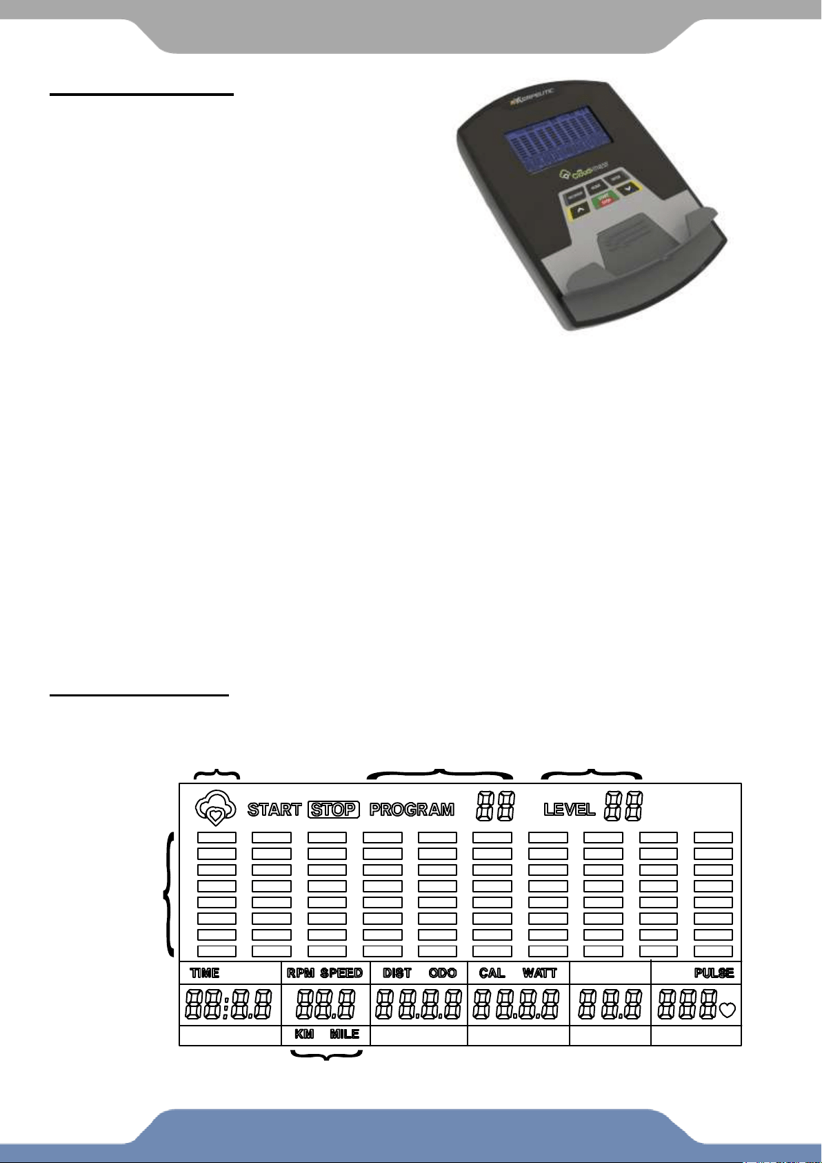
Console Display:
These are all the LCD tiles that may show while using the workout equipment.
Program Number
Resistance
APP Connection Icon
R
e
s
i
s
t
a
n
c
e
Distance Tracking Units
22
CONSOLE
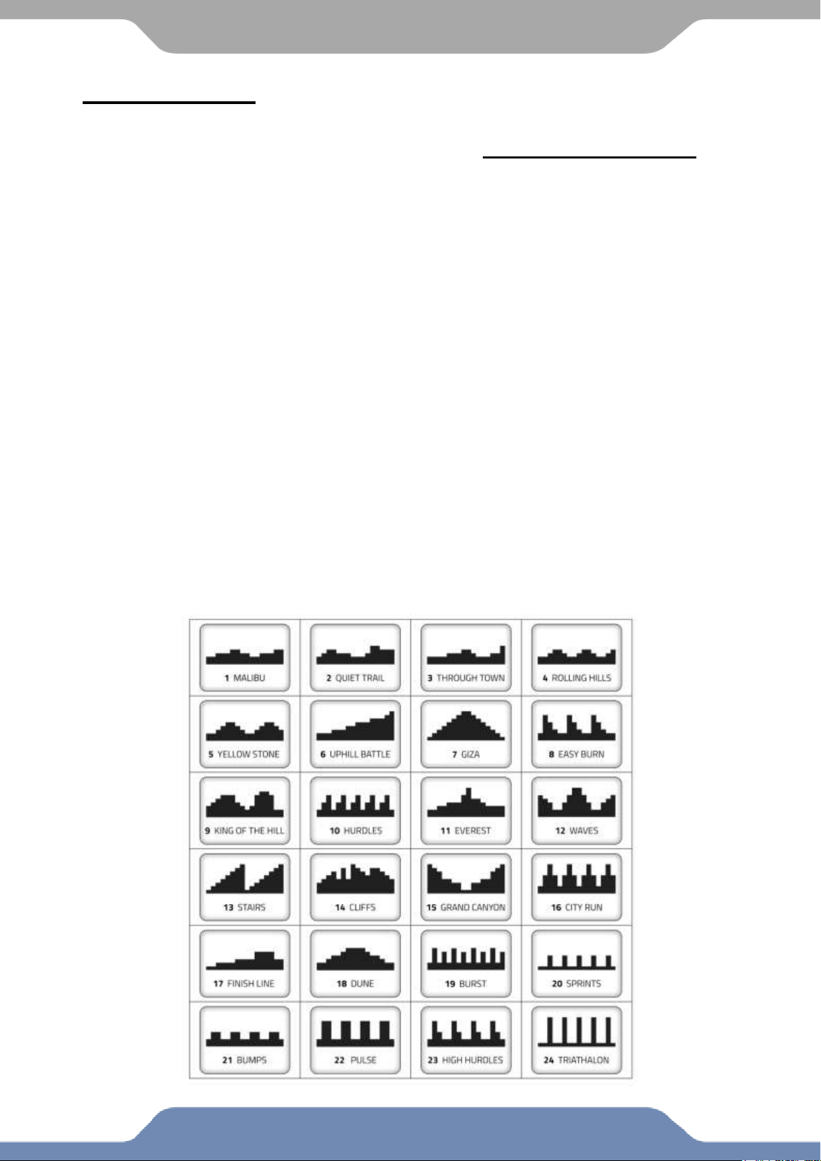
Profile Program:
The console has 24 Preset Program options to choose from to help
challenge you and meet your fitness goals. See the diagram below.
How to quick start a Program Profile: The first screen that appears when the
console is turned on is program profile P1. From this screen you can select any of the
other program profiles by using the UP or DOWN buttons. To start an immediate workout
press the START button once you have selected the desired program profile. Control the
resistance level by pressing the UP or DOWN arrow buttons.
The console can be set to count down a Workout Goal based on
TIME, DISTANCE, and CALORIES.
How to set a Workout Goal Program Profile: The first screen that appears when
the console is turned on is program profile P1. From this screen you can select any of the
other program profiles by using the UP or DOWN buttons. Pressing the ENTER button will
select the program profile on the screen. Next, the TIME goal parameter will flash. You
can assign a value from which the console will count down by using the UP or DOWN
buttons or press ENTER again to set a DISTANCE or CALORIE goal. Press the START
button to initiate your workout. When a goal is achieved the console will sound an alarm
and stop the workout.
Note 1: Multiple Workout Goals can be set. When one of the parameter reaches zero
the console will stop your workout. To continue your workout and reach the other
Workout Goals you have set, press the START button twice in order to resume.
Note 2: The FULL workout diagram will not display on the LCD screen during the
workout. The diagram will shift during the workout.
23
CONSOLE
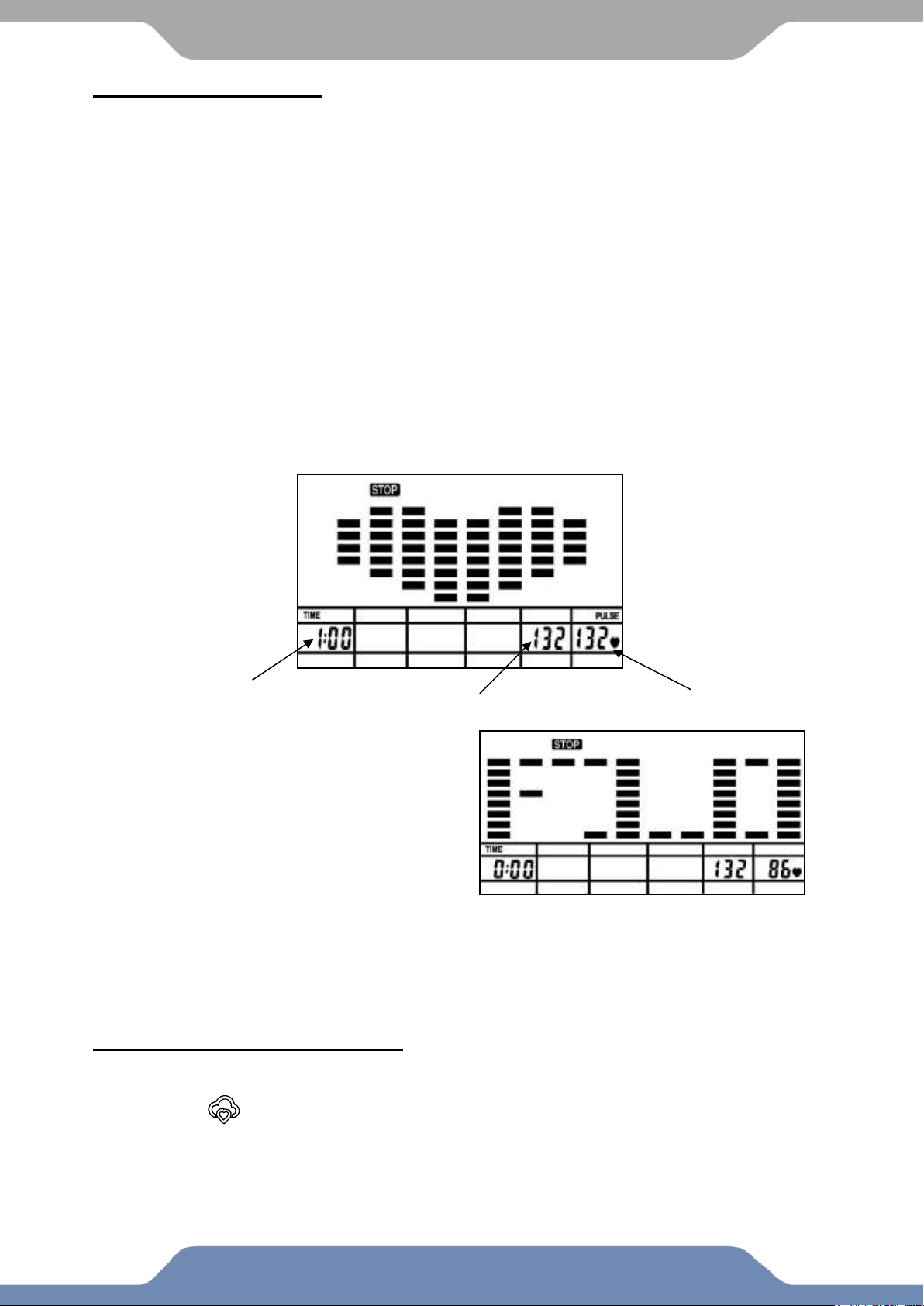
Recovery Program:
The Recovery Program gives you feedback about the rate at which you heart recovers
after a workout. The recovery rating is a value in which your personal fitness can be judged.
Your recovery rating is calculated by evaluating how large the difference is between your
peak heart rate at the end of a workout and your heart rate after 60 seconds of resting.
How it works: The larger the difference between your peak heartrate and your resting
heartrate after 60 seconds, the better your recovery rating. A fit person’s heart rate will
decrease faster and be scored closer to F1.
How to activate Recovery Program: After your workout stop pedaling and hold the
heart rate sensors so the console detects a pulse. Push the RECOVERY button. A large
heart will be displayed on the screen, along with your highest heart rate during the test, your
current heart rate, and the time remaining for the test. The test will last 60 seconds, hold the
heart rate sensors for the entire duration. Once the test is complete, the console will beep 3
times, and display your score. The two heart rate values (your highest heart rate and your
heart rate at the end of the test) will continue to be displayed on the lower right corner.
The fitness ranking
F1 – excellent fitness
F2 – good fitness
F3 – satisfactory fitness
F4 – minimal fitness
F5 – fitness needs improvement
F6 – fitness needs major improvement
Additional Console Notes:
1. The console will shut off after 20 minutes of inactivity.
2. The will show on the display when the APP is connected with the console.
a. The console buttons will not respond while the APP is connected. All
controls of the console needs to be done through the app.
Score screen: F1.0
Highest heart rate during
the test
Current heart rate
60 second countdown
Note: These ranking are for very basic fitness tracking, for more accurate health
information consult with your personal care physician.
24
ADJUSTMENT
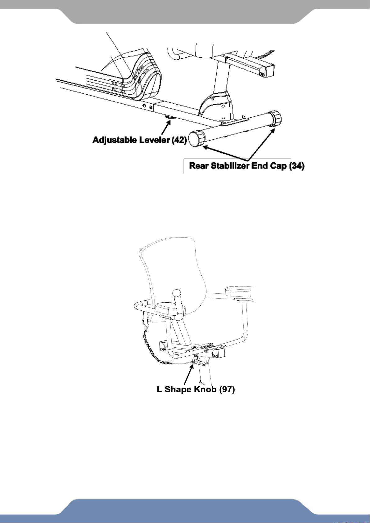
Adjusting the Rear Stabilizer End Cap and the Adjustable Leveler:
To prevent shaking during a workout adjust the Rear Stabilizer End Caps (34)
and the Adjustable Leveler (42) as needed to the level the Bike with the ground.
Adjusting the Seat Forward or Back
Turn the L Shape Knob (97) in a counter-clockwise direction until the seat can
slide freely. Position the seat to a comfortable position and lock the seat in place
by turning the L shape knob (97) clockwise until tightly secured.
25
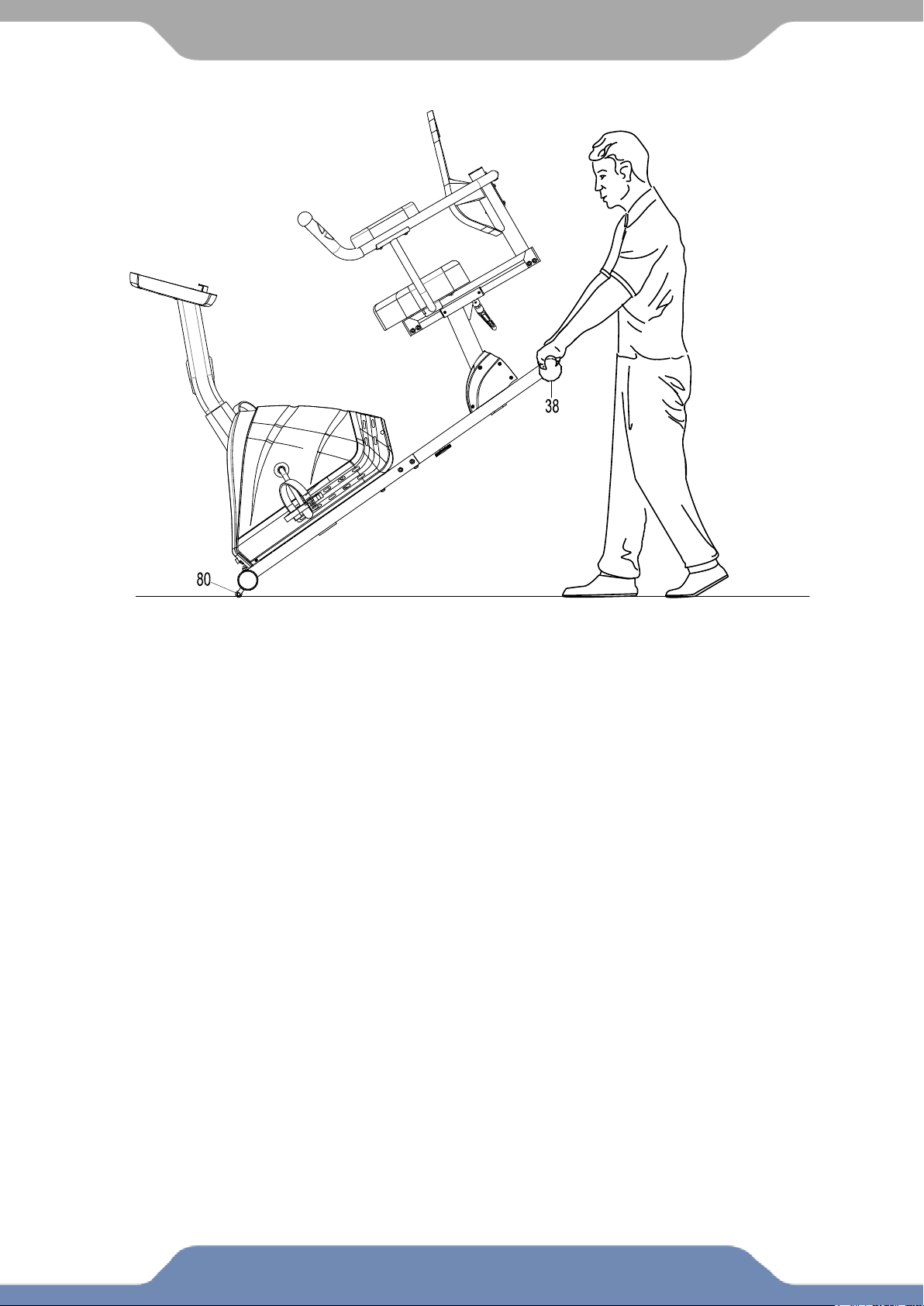
TRANSPORTING
Transporting the Bike
Hold the Rear Stabilizer (38) and lift up the machine until the Transport Wheel (80)
make contact with the floor. Push or pull the unit to the desired location, then gently
lower the Rear Stabilizer (38) to the ground.
STORAGE
Store the recumbent bike in a clean and dry environment away from children and pets.

26
TROUBLE SHOOTING & MAINTENANCE
TROUBLE SHOOTING:
PROBLEM: The recumbent bike wobbles when in use.
SOLUTION: Turn the Rear Stabilizer End Caps on the Rear Stabilizer or the Adjustable
Leveler on the bottom of the Rear Main Frame as needed to level the recumbent bike.
See the Adjustments Section.
PROBLEM: There is no display on the computer console.
SOLUTION: Remove the Computer and verify that the wires that come from the
Computer are properly connected to the wires that come from the Front Post.
SOLUTION: Unplug the AC adaptor, Wait 30 seconds and plug it back in.
PROBLEM: There is no heart rate reading or the heart rate reading is erratic or
inconsistent.
SOLUTION: Make sure that the wire connections for the Hand Pulse Sensors are
securely connected.
SOLUTION: Be sure to hold on to the Hand Pulse Sensors with two hand at all times.
This will ensure that the reading is accurate.
SOLUTION: Avoid gripping the hand pulse sensors too tightly. Try to maintain moderate
pressure while holding onto the hand pulse sensors.
PROBLEM: The recumbent bike makes a squeaking noise when in use.
SOLUTION: The bolts may be loose on the recumbent bike. Inspect all of the bolts and
tighten any loose bolts.
PROBLEM: Console displays E1
SOLUTION: Symptoms include an unusually loud noise coming from the Motor, which
means the Gears are NOT meshing correctly. Unplug the console and try reversing the
resistance and try again. If this fails then contact customer service.
PROBLEM: Console displays E2
SOLUTION: Check if the cables connected during assembly are correctly plugged in.
PROBLEM: Console shows KM instead of MILES for speed and distance
SOLUTION: Reset the console by pressing STOP for 3 seconds. Press and hold UP and
DOWN buttons for 3 seconds.
MAINTENANCE:
CLEANING
1. The recumbent bike can be cleaned with a soft clean damp cloth.
2. Do not use abrasives or solvents on the plastic parts.
3. Wipe your perspiration off the recumbent bike after each use.
4. Be careful not to get excessive moisture on the console display as this might cause
an electrical hazard or the electronics to fail.
5. Keep the recumbent bike, especially the computer console out of direct sunlight to
prevent screen damage.
6. Inspect that all assembly bolts, nuts, screws, and pedals on the machine are
thoroughly tightened every week. Tighten any loose parts.

27
WARRANTY
MANUFACTURER’S LIMITED WARRANTY
Paradigm Health & Wellness warrants to the original purchaser that this product is free from
defects in material and workmanship when used for the purpose intended, under the
conditions that it has been installed and operated in accordance with Paradigm’s Owner’s
Manual. Paradigm’s obligation under this warranty applies to the following:
COMPONENT LENGTH OF WARRANTY
Structural Frame 1 year
All Other Components 90 days
(computer display, electronics, upholstery, foam, ball bearings, pulleys, belts, cables, wires,
shocks, covers, tension, internal mechanism, wheels, pedals, knobs, accessories and
hardware)
Exclusions from Warranty Coverage:
Paradigm does not warrant against and is not responsible for, and no implied warranty shall be deemed to cover, any
product failure, product malfunction, or damages attributable to:
1. Improper installation and/or failure to abide by Paradigm’s installation guidelines;
2. Use of this product beyond normal home use, or in an application for which it was not designed;
3. Cosmetic items such as scratches, dents or discolorations;
4. Damage caused by normal wear and tear, vandalism, accidental or by animals;
5. Any act of Nature (such as fire, flooding, snow, ice, hurricane, earthquake, lightning or other natural disaster),
environmental condition (such as air pollution, mold, mildew, etc.), or staining from foreign substances (such as dirt,
grease, oil, etc.);
6. Normal weathering due to exposure to sunlight, weather and atmosphere which can cause colored surfaces to,
among other things, flake, chalk, accumulate dirt or stains.
7. Improper operation, alteration, handling, storage, abuse or neglect of the products.
Paradigm, using its sole discretion, will either repair or replace free of charge any part(s) proven to
be defective under normal home use. Any repair or replacement shall provide no new warranty
coverage, but shall retain only the remaining portion of the original product’s warranty. This
warranty is offered only to the original purchaser and is not transferable. Proof of original
purchase is required.
Ordering Replacement Parts
Replacement parts can be ordered by emailing our customer service department:
Service@paradigmhw.com
Open Daily 8:00 AM - 5:00 PM (PST).
When ordering replacement parts please have the following information ready:
1. Owner’s Manual
2. Model Number
3. Description of Parts
4. Part Number
5. Date of Purchase

28
PARTS REQUEST FORM
Paradigm Health & Wellness, Inc.
EMAIL THIS FORM WITH YOUR RECEIPT OF PURCHASE TO
Service@paradigmhw.com *
NAME:_____________________________________________________________________________________
ADDRESS:__________________________________________________________________________________
CITY:________________________ STATE:_____________ ZIP:_______________________________________
TELEPHONE: (Day)______________________________________________________________________
(Night)_____________________________________________________________________
SERIAL#:___________________________________________________________________________________
MODEL#:___________________________________________________________________________________
PURCHASE DATE:___________________________________________________________________________
PLACE OF PURCHASE:_______________________________________________________________________
“YOUR ORDER WILL BE PROCESSED WITHIN 3 BUSINESS DAYS”
This form can also be faxed to #: 626-810-2166
PART #
DESCRIPTION
QTY
