OWNER’S MANUAL
4318.2-021419
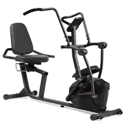
Elliptical
IMPORTANT: Read all instructions carefully before using this product. Retain this
owner’s manual for future reference. The specifications of this product may vary from
this photo and, subject to change without notice.

THIS PAGE WAS INTENTIONALLY LEFT BLANK


1
TABLE OF CONTENTS
SERVICE ------------------------------------------------------------------------ 2
IMPROTANT SAFETY GUIDELINES ------------------------------------- 3
PRODUCT SAFETY ---------------------------------------------------------- 4
OVERVIEW DRAWING ------------------------------------------------------ 6
PART LIST ----------------------------------------------------------------------- 7
HARDWARE PACK & TOOLS PACK-------------------------------------- 8
ASSEMBLY ---------------------------------------------------------------------- 9
CONSOLE-- -------------------------------------------------------------------- 19
ADJUSTMENTS --------------------------------------------------------------- 21
TRANSPORTING THE ELLIPTICAL-------------------------------------- 22
TROUBLE SHOOTING & MAINTENANCE ----------------------------- 23
WARRANTY -------------------------------------------------------------------- 24
PARTS REQUEST FORM --------------------------------------------------- 25

2
SERVICE
IMPORTANT: FOR NORTH AMERICA ONLY
For damaged or defective product, questions, replacement parts or any other service
support, please contact our customer service department by the below methods:
For The Best Service, please Email:
service@paradigmhw.com
Response Time: 1-2 Business Days
Emailing us with the information above will be the best method to receive a response during
peak business hours
Website:
www.paradigmhw.com
Toll-Free:
1-844-641-7921
(8:00 AM - 5:00 PM Pacific Standard Time, Monday thru Friday)
Response time may vary via calling
Please have the following information ready when requesting for service:
Your name
Phone number
Model number
Serial number
Part number
Proof of Purchase
For damaged or defective product please contact our customer service before returning to
the store.
Paradigm Health & Wellness, Inc.
1189 Jellick Ave.
City of Industry, CA 91748, USA
3
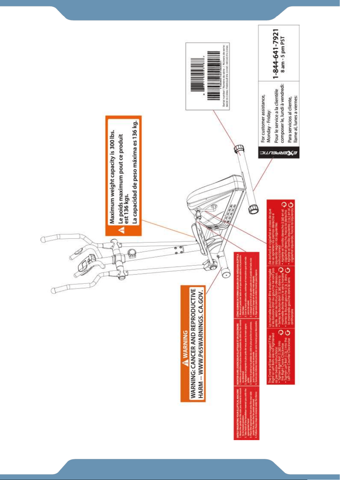
LABEL PLACEMENT

4
IMPORTANT SAFETY GUIDELINES
Read all guidelines before using this machine. When using this machine,
basic precautions should always be followed, including the following:
WARNING - To reduce the risk of injury to persons:
1. Make sure your equipment is correctly assembled before you use it.
2. Be sure all screws, nuts, and bolts are tightened prior to use.
3. Before using this equipment, we recommend doing warm ups.
4. Only one person should be using the equipment at a time.
5. Never operate this Equipment if it is damaged, if it is not working properly, has been dropped, or
damaged. If a problem is encountered contact Customer Service before using the equipment
again.
6. Always use this equipment on a clear and level surface.
7. For household use only.
8. Do not use outdoors or near water.
9. Use the machine only for its intended use as described in this manual. Do not use attachments not
recommended by the manufacturer.
10. Do not wear loose clothing when using the equipment.
11. Never drop or insert any object into any opening.
12. If at any time you feel faint, light-headed, or dizziness while operating the equipment, stop
exercising immediately. You should also stop exercising if you are experiencing pain or any
discomfort.
13. For any problems contact customer service. Servicing should be performed by an authorized
service representative. Our contact number is on the service page.
14. This product requires a minimum of 6 square feet of space for safe operation.
15. Be careful to always hold onto the handlebars when you’re mounting and dismounting.
16. Be careful to have the pedals at their lowest point when stepping off.
17. Hold onto the handlebars and use both the pedals in tandem to ensure a smooth, effective
workout.
18. Warning: - Risk of Personal Injury - Consult with your personal physician to see if exercise
equipment is appropriate for you. This is especially important for people with pre-existing health
problems. Do not use this equipment without your physician's approval.
19. Warning: - Risk of Personal Injury – Do not allow children to use this machine.
20. Warning: - Risk of Personal Injury - Keep children under the age of 13 away from the
machine.
21. Warning: - Risk of Personal Injury – Keep body parts, hair, loose clothing, and jewelry
clear of all moving parts.
22. Warning: - Risk of Personal Injury - Do not attempt to service the unit yourself. Discontinue
use and contact customer service.
23. Warning: - To Reduce The Risk Of Personal Injury - Read And Understand All Read The
Instructions Before Using This Machine
24. WARNING: CANCER AND REPRODUCTIVE
HARM--WWW.P65WARNINGS.CA.GOV.

5
The product weighs more than 44 lbs. It is heavily
recommended that at least 2 persons assemble.
IMPORTANT SAFETY GUIDELINES
Do not use this equipment if you have any of the following conditions or ailments:
Pregnancy
Extreme obesity
Middle ear infection
Hiatus hernia or Ventral hernia
Glaucoma, retinal detachment or conjunctivitis
Use of anticoagulants including Aspirin in high doses.
Spinal injury, Cerebral Sclerosis, or acutely swollen joints
Heart or circulatory disorders for which you are being treated
High blood pressure, Hypertension, Recent stroke or Transient Ischemic attack
Bone weaknesses including Osteoporosis, Unhealed fractures, Modular pins, or surgically implanted
orthopedic supports.
DO NOT EXCEED THE MAXIMUM RATED WEIGHT CAPACITY
The Maximum Weight Capacity for this product is 300 lbs/136 kgs.
RETAIN THIS OWNER’S MANUAL AND KEEP THE ORIGINAL
PURCHASE RECEIPT FOR FUTURE REFERENCE.
&
SAVE THESE GUIDELINES
!
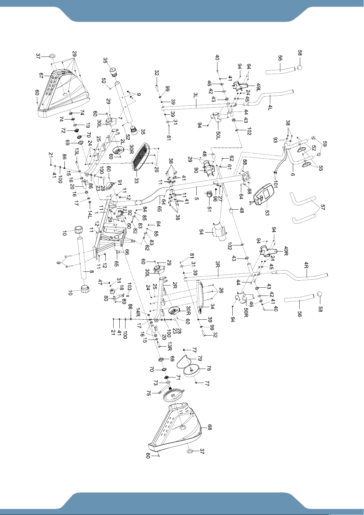
6
OVERVIEW DRAWING

7
PARTS LIST
No.
Description
Qty
No.
Description
Qty
1
Main Frame
1
27
Tension Cable 1800
1
2R
Right Foot Bar
1
28
Nut Cap S13
2
2L
Left Foot Bar
1
29
Self-Tapping Phillips Screw ST4.2*25
11
3L
Left Handrial Post
1
30L
Left Foot Bar Cover
2
3R
Right Handrail Post
1
30R
Right Foot Bar Cover
2
4L
Left Handrail Arm Ф32*1.5
1
31
Big Flat Washer Ф6*Ф18*1.5
3
4R
Right Handrail Arm Ф32*1.5
1
32
Boltφ15.8*62.5
2
5
Front Post
1
33
Left Pedal 395*150*65
1
6
Handlebar Ф25*1.5
1
34
Right Pedal 395*150*65
1
7
Front Stabilizer Ф60*1.5*480
1
35
Front Stabilizer End Cap
2
8
Rear Stabilizer
1
37
Crank Cover φ40*φ25*10
2
9
Carraige Bolt M8*70
4
38
Socket Hex Bolt S6-M8*15 全牙
10
10
Rear Stabilizer End Cap
2
39
Bushing φ14.2*φ10.2*10
4
11
Curve Washer φ20*φ8
12
40
Socket Hex Bolt S6 M8*20
2
12
Cap Nut M8
4
41
Spring Washer φ8
14
13L
Left Pedal Bolt
1
42
D Washer φ38*3
2
13R
Right Pedal Bolt
1
43
Bushing φ38,φ32,φ19,14
4
14L
Left Nylon Nut
1
44
Carriage Bolt M6*35
4
14R
Right Nylon Nut
1
45
Curve Washer Φ6
4
15
Wave Washer φ28*φ17*0.3
2
46
Big Flat Washer φ8
2
16
Bushing Ф24.5*Ф16*14
4
47
Phillips Screw M6*10
1
17
Spring Washer Ø20
2
48
Bushing φ32*φ16*5*φ50
2
18
Pressing Wheel
1
49R
Right Front Handlebar Cover
1
19
Flat Washer 7/8”
1
49L
Left Front Handlebar Cover
1
20
U-Shape Bracket
2
50R
Right Rear Handlebar Cover
1
21
Lock Nut M8
2
50L
Left Rear Handlebar Cover
1
23
Hex Bolt M8*45
2
51
Tension Control Knob
1
24
Lock Nut M6
10
52
Self-Tapping Phillips Screw ST4.2*20
4
25
Flat Washer Φ6
6
53
Console
1
26
Hex Bolt M6*40 L20
6
54
Rear Front Post Cover
1

8
PARTS LIST
No.
Description
Qty
No.
Description
Qty
55
Hand Pulse Sensor
2
81
Phillips Screw M6*15
2
56
Foam Grip φ31*φ37*480
2
82
Eye Bolt M6*36
2
57
Foam Grip φ27*φ33*360
2
83
U Shaped Bracket
2
58
Ball Cap
2
84
Hex Nut M6
2
59
Round Cap
2
85
Spring Washer Ø6
2
60
Self-Drilling Phillips Screw ST4.2*25
8
86
Bushing φ18*φ8*5
4
61
Curve Washer Ф20*Ф5.2
1
88
Phillips Screw M5*10
2
62
Phillips Screw M5*55
1
89
Socket Hex Bolt M8*10
1
64
Sensor Wire ⅠL=1100
1
90
Front Post Cover
1
65
Sensor Wire ⅡL=1600
1
91
Left Main Frame Cover
1
66
Self-Tapping Screw ST2.9*12
2
92
Right Main Frame Cover
1
67
Left Cover
1
93
Curve Washer φ16*φ8
2
68
Right Cover
1
94
Self-Tapping Phillips Screw ST4.2*15
8
69
Bearing Cup Ф51.5
2
96
Clip13.5*18*11.5
1
70
Ball Bearing
2
97
Screw ST4.2*20
2
71
Bushing 15/16”
1
98
Socket Hex Bolt M8*25
1
72
Bushing 7/8”
1
99
Spring Washer with External Teeth
φ10*φ18*1
2
73
Flat Washer φ34.5*φ23*2.5
1
100
Big Flat Washer φ25*φ8.2
4
74
Flat Hex Nut 7/8”
2
101
Hand Pulse Sensor Wire
2
75
Pulley with Crank 6.5″/Φ260
1
102
Wave Washer φ19*φ26*0.3
2
77
Flange Nut M10*1.0
2
103
Hex Bolt M8*25
1
78
Idle Wheel Ф230*40*32
1
79
Belt
1
80
Idle Wheel Bracket
1
9
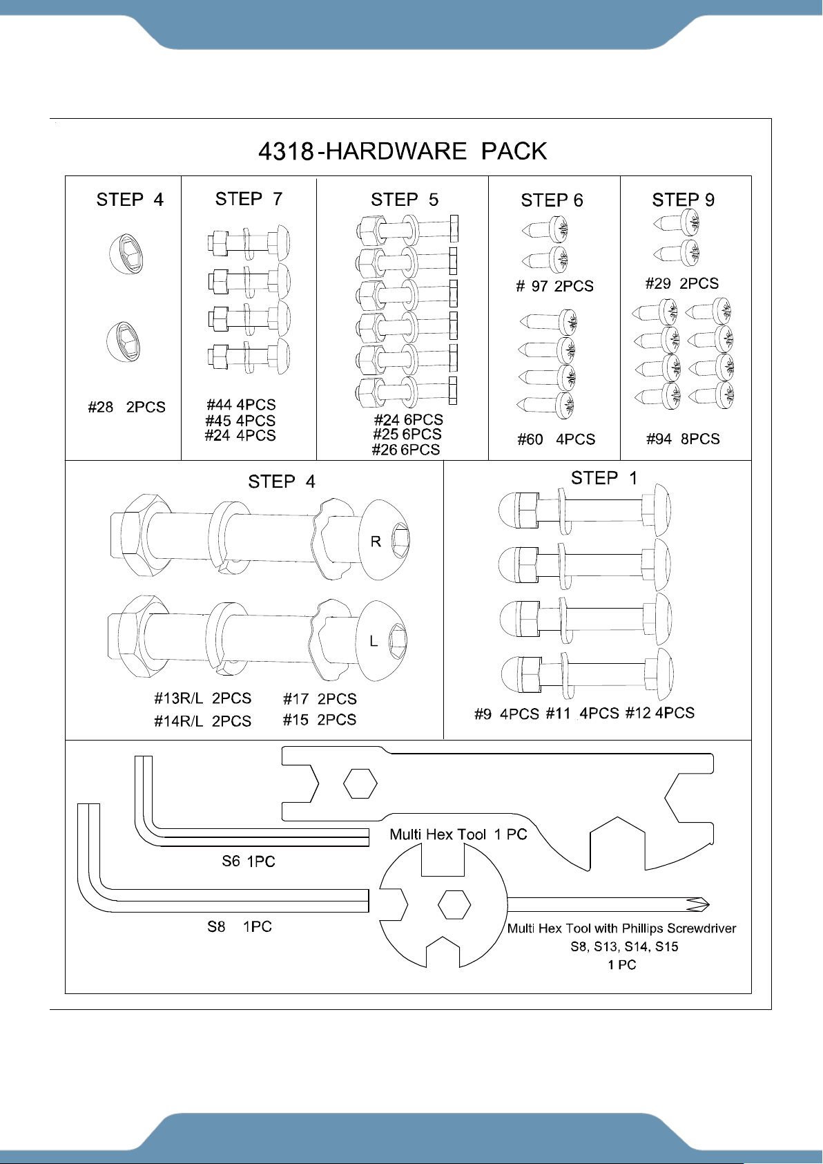
HARDWARE & TOOLS PACK
10
ASSEMBLY
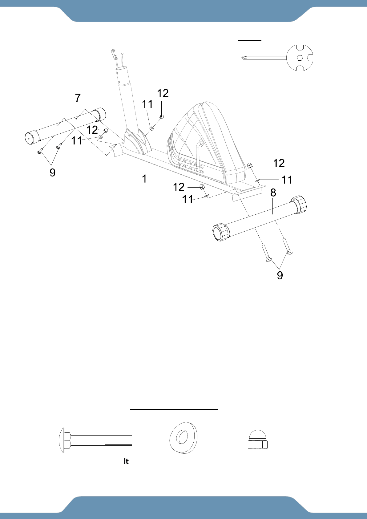
STEP 1
1a. Installing the Front Stabilizer – Align the Front Stabilizer (7) onto the front curve of
the Main frame (1). Make sure the transport wheels are positioned toward the front and
parallel to the floor. Install two Carriage Bolts (9) from the bottom, and on the other ends
of the bolts attach two Curve Washers (11) and two Cap Nuts (12). Use the Multi Hex
Tool with Phillips Screwdriver to tighten the Cap Nuts (12) until secure.
1b. Installing the Rear Stabilizer – Align and Install the Rear Stabilizer (8) onto the rear
curve of the Main frame (1) using two Carriage Bolts (9), two Big Curve Washers (11),
and two Cap Nuts (12). Securely tighten the Cap Nuts (12) with the Multi Hex Tool with
Phillips Screwdriver provided.
HARDWARE PACK
(9) Carriage Bolt
4 PCS
(11) Curve Washer
4PCS
(12) Cap Nut
4PCS
Multi Hex Tool with Phillips
Screwdriver
1 PC
TOOL
11
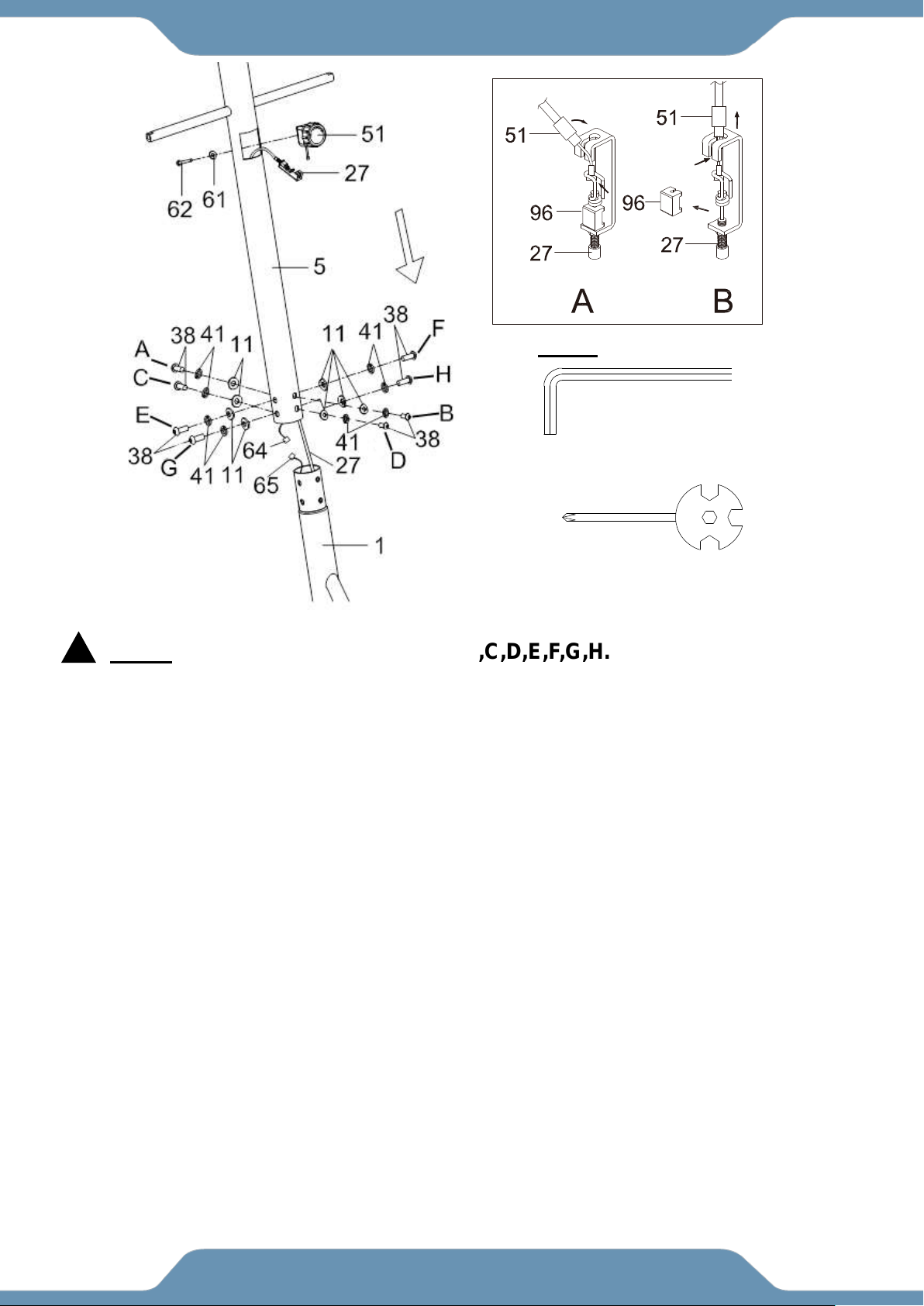
ASSEMBLY
MUST TIGHTEN IN SEQUENCE: A,B,C,D,E,F,G,H.
STEP 2
2a. Removing The Hardware From The Front Post – Use the 6mm Allen Wrench to remove
eight Socket Hex Bolts (38), eight Curve Washers (11), and eight Spring Washers (41) from the Main
Frame (1).
2b. Connecting The Console Wires – Insert the Tension Cable (27) into the Front Post (5) and pull it
out through the square hole on the top of the Front Post (5). Connect the Sensor Wires (64) and (65).
Make sure the wires stay connected.
2c. Installing The Front Post – Place the Front Post (5) onto the Main Frame (1). Reinstall the
previously removed hardware: eight Socket Hex Bolts (38), eight Curve Washers (11), and eight
Spring Washers (41) and securely tighten the bolts in sequence using the 6mm Allen Wrench
provided.
2d. Installing the Tension Control Knob –Remove the Phillips Screw (62) and Curve
Washer (61) from the back of the Tension Control Knob (51). Turn the Tension Control
Knob (51) to the highest tension setting. Attach the end of the resistance cable on the Tension
Control Knob (51) into the spring hook of the Tension Cable (27) (See Fig. A). Pull the
Resistance Cable of the Tension Control Knob (51) up and gently remove the Clip (96) (See
Fig. B). Install the Tension Control Knob (51) in to the Front Post (5) using the Phillips
Screw (62) and Curve Washer (61) previously removed. Then tighten with the Multi Hex tool
with Phillips Screwdriver provided.
6mm Allen Wrench 1PC
TOOL
!
Multi Hex Tool with Phillips Screwdriver
1 PC
Fig.
Fig.
12
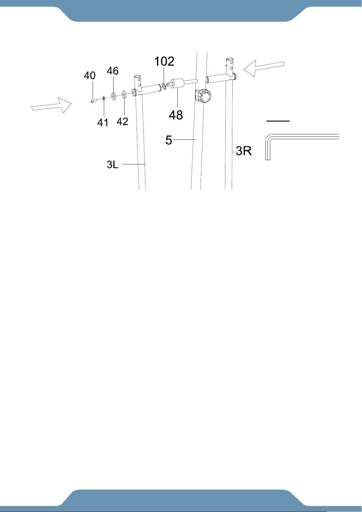
ASSEMBLY
STEP 3
3a. Removing The Hardware From The Front Post–Remove the Pre-Installed Hexagon Socket
Head Bolts (40), Spring Washers (41), Big Washers (46), Washers (42), and Wave Washers
(102) from the left and right horizontal posts on the Front Post (5).
3b. Installing The Left Handrail Post –Slide a Plastic Bushing (48) and a Wave Washer (102)
down the horizontal shaft on the left side of Front Post (5), and then attach the Left Handrail Post
(3L) onto the left horizontal post on the Front Post (5). Secure it using one Socket Hex Bolt (40),
one Spring Washer (41), one Big Washer (46), and one Washer (42) that was removed
previously. Tighten the Socket Hex Bolt (40) using the 6mm Allen Wrench provided.
3c. Installing The Right Handrail Post – Repeat the same assembly steps above for installing the
Right Handrail Post (3R) onto the right rod of the Front Post (5).
6mm Allen Wrench
1PC
TOOL
13
ASSEMBLY
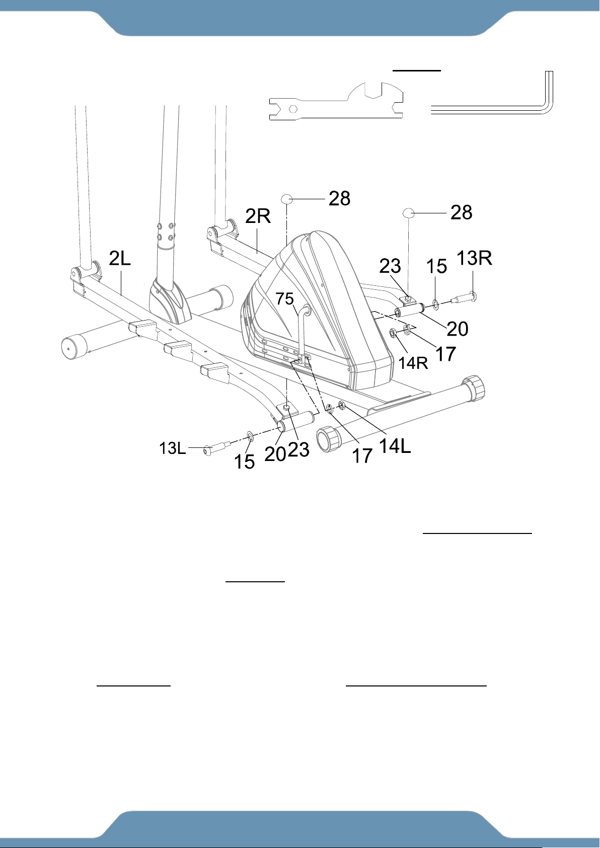
STEP 4
4a. Left Foot Bar Installation –Insert the Left Bracket Bolt (13L) along with a Wave Washer (15)
through the U Shaped Bracket (20) located on the back of the Left Foot Bar (2L). Secure the Left
Bracket Bolt (13L) to the Left side of the Crank (75) by turning the Bolt Counter-Clockwise.
Tighten the Left Bracket Bolt (13L) with the 8mm Allen Wrench provided. Next, install a Spring
Washer (17) and Left Nylon Nut (14L) on the remaining threads of the Left Bracket Bolt (13L).
Turn the Left Nylon Nut (14L) in a Clockwise direction, and then tighten using the 8mm Allen
Wrench and Multi Hex Wrech provided. Then place the Nut Cap (28) onto the Head of the Hex
Bolt (23).
4b. Right Foot Bar Installation – Repeat the above assembly steps to install the Right Foot Bar
(2R) into the Right Crank (75). When installing the Right Pedal Bolt (13R) turn the Right Pedal
Bolt (13R) CLOCKWISE and the Right Nylon Nut (14R) COUNTER-CLOCKWISE.
8mm Allen Wrench
1PC
TOOLS
Multi-Hex Wrench
1PC
14
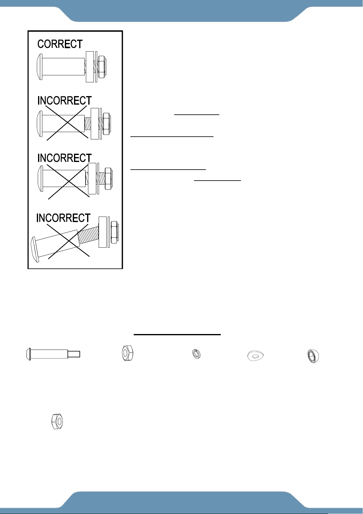
ASSEMBLY
NOTE: Look to Fig. C for the correct installation of the Pedal Bolts
.
Keep the bolt perfectly straight when the bolt goes through the
Foot
Bars, and is being screwed into the Crank correctly. If the bolt is
screwed into the crank at an angle, this may damage the
equipment.
Installing Right Pedal Bolt into Right Crank can only be done
by turning it CLOCKWISE. Installing the Left Pedal Bolt into the
Left Crank can only be done by turning
COUNTER-CLOCKWISE.
Installing the Right Nylon Nut can only be done by turning it
COUNTERLOCKWISE. Installing the Left Nylon Nut can only be
done by turning it CLOCKWISE.
HARDWARE PACK
(17) Spring Washer
2PCS
(15) Wave Washer
2PCS
(13R/L) Right / Left Pedal
Bolt 2PCS
(14R) Right Nylon Nut
1PC
(28) Nut Cap
2PCS
(14L) Left Nylon Nut
1PC
Fig. C
15
ASSEMBLY
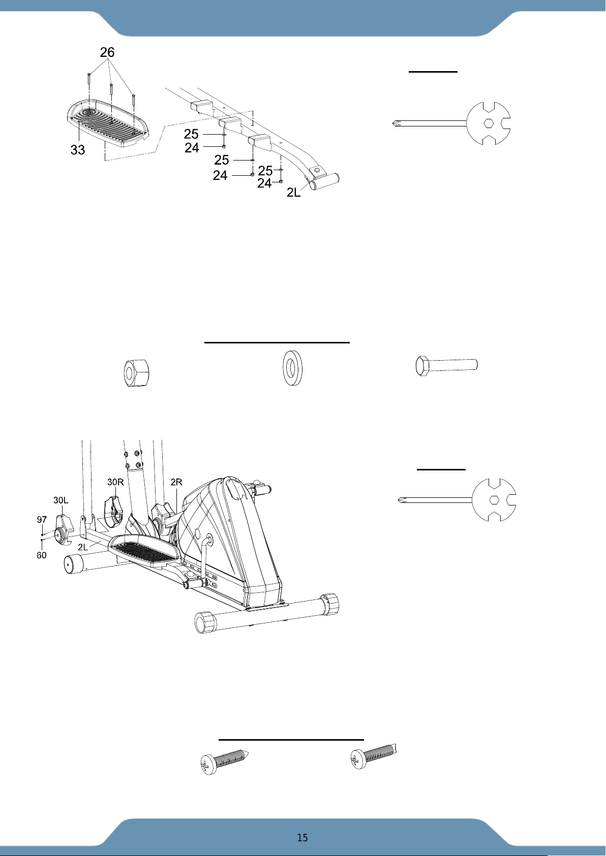
STEP 5
5a. Pedal Installation – Install the Left Pedal (33) onto the Left Foot Bar (2L) using three Bolts
(26), three Flat Washers (25) and three Lock Nuts (24). Tighten the Lock Nuts (24) using the
Multi Hex Tool with Phillips Screwdriver provided.
Repear the same step to attach the Right Pedal (34) to the Right Foot Bar (2R).
----------------------------------------------------------------------------------------------------------------------------------
STEP 6
6. Foot Bar Cover Installation - Attach the Left and Right Foot Bar Covers (30L,30R) onto the
Left Foot Bar (2L) using one Screw (97) and two Self-Drilling Phillips Screws (60). Tighten
using the Multi Hex Tool with Phillips Screwdriver provided.
*Repeat these steps for the Right Foot Bar (2R).
(24) Lock Nut
6 PCS
(25) Washer
6 PCS
(26) Bolt
6 PCS
HARDWARE PACK
Multi Hex Tool with Phillips Screwdriver
1 PC
Multi Hex Tool with Phillips Screwdriver
1 PC
(60) Self-Drilling Phillips Screw
4 PCS
(97) Screw
2PCS
HARDWARE PACK
TOOLS
TOOLS
16
ASSEMBLY
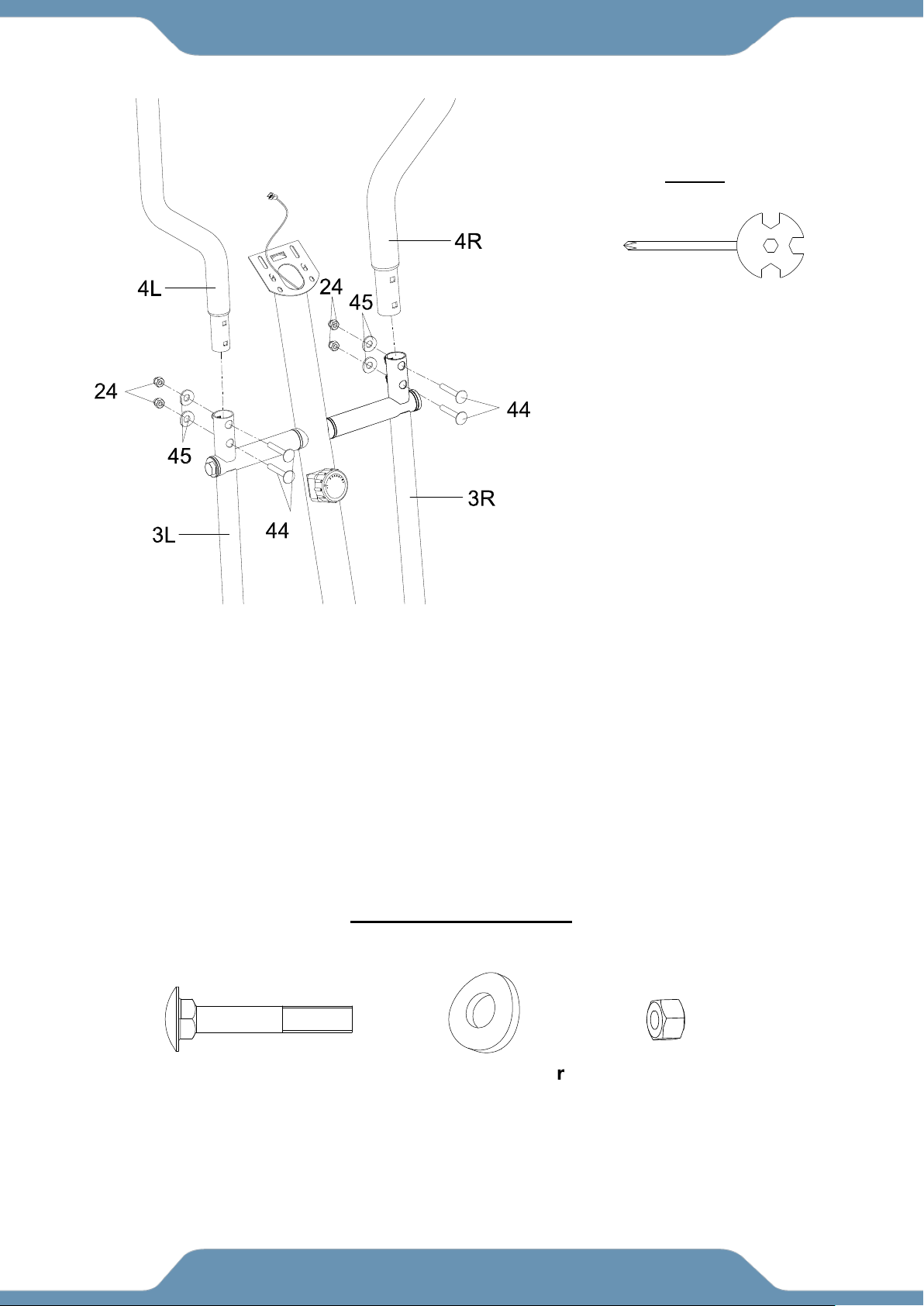
STEP 7
7a. Installing the Left Handrail Arm – Insert the Left Handrail Arm (4L) onto the Left Handrail
Post (3L) using two Carriage Bolts (44), two Curve Washers (45) and two Lock Nut (24). Tighten
the Lock Nut (24) using the Multi Hex Tool with Phillips Screwdriver provided.
7b. Installing the Right Handrail Arm – Insert the Right Handrail Arm (4R) onto the Right
Handrail Post (3R) using two Carriage Bolts (44), two Curve Washers (45) and two Lock Nut
(24). Tighten the Lock Nut (24) using the Multi Hex Tool with Phillips Screwdriver provided.
TOOL
HARDWARE PACK
(44) Carriage Bolt
4 PCS
(45) Curve Washer
4 PCS
(24) Lock Nut
4 PCS
Multi Hex Tool with Phillips Screwdriver
1 PC
17
ASSEMBLY
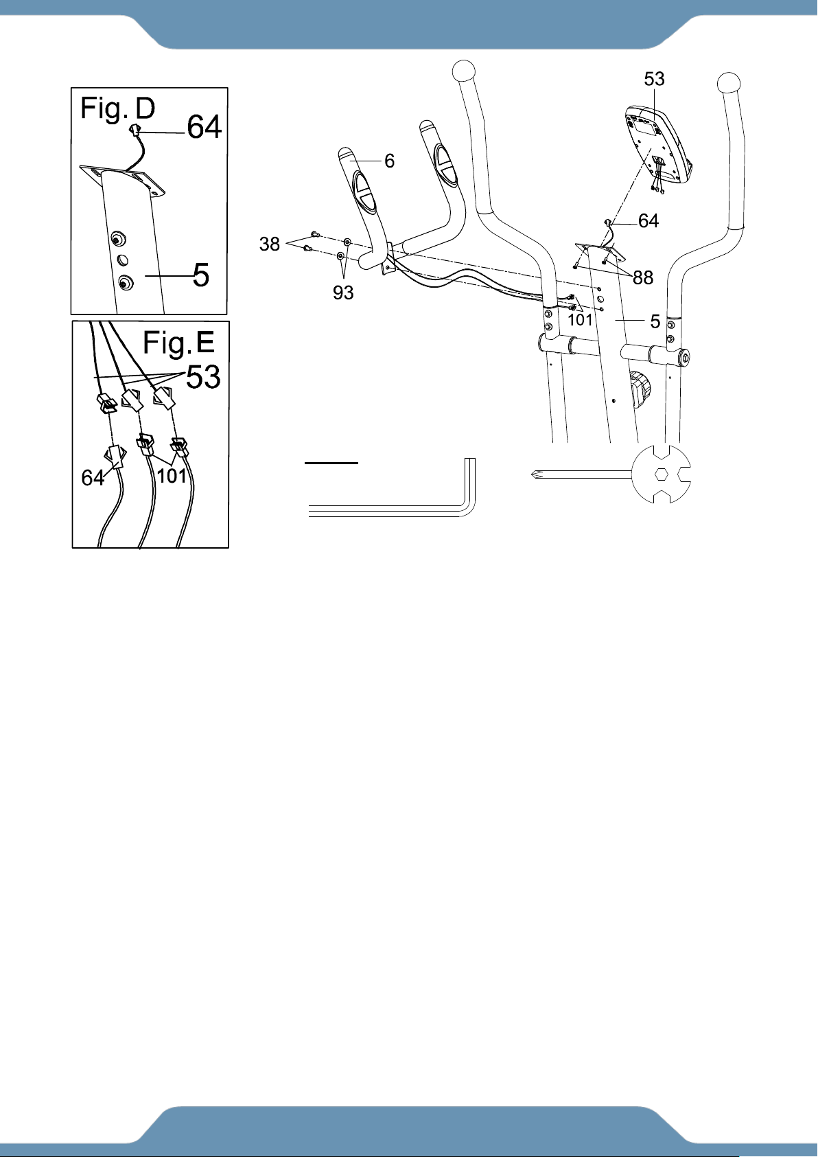
8a. Hardware Removal- Remove the two Phillips Screws (88) from the back of the Console (53).
Then remove the two Socket Hex Bolts (38) and two Curve Washers (93) from the Front Post (5).
8b. Console Installation - Insert the Hand Pulse Sensor Wires (101) from the Handlebar (6) into the
hole on the forward facing side of the Front Post (5), and pull them up, and out of the top end of the
Front Post (5). Connect the Hand Pulse Sensor Wires (101) to the Sensor Wires coming from the
back of the Console (53). Then connect the Sensor Wire I (64) to the connection Sensor Wire coming
from the back of the Console (53) (See Fig. E). Place the Console (53) onto the plate on the Front
Post (5) and secure it into place using the two Bolts (88) and tighten using the Multi Hex Tool with
Phillips Screwdriver provided.
8c. Handlebar Installation - Attach the Handlebar (6) onto the Front Post (5) using the two Bolts (38)
and two Curve Washers (93) that were previously removed. Then tighten using the 6mm Allen
Wrench provided.
6mm Allen Wrench
1PC
TOOL
Multi Hex Tool with Phillips
Screwdriver
1 PC
18
ASSEMBLY
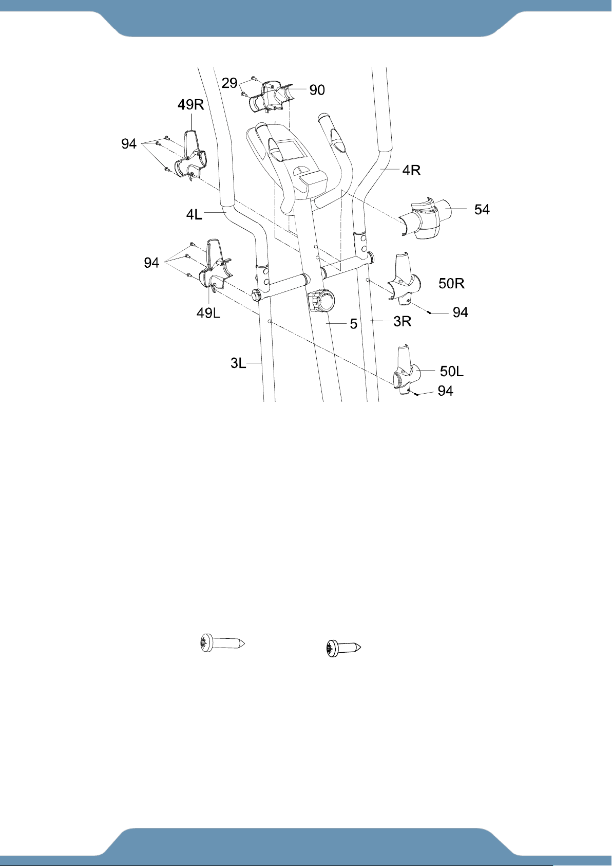
9a. Cover Installation - Attach the Front and Rear Front Post Covers (90, 54) onto the Front Post (5)
using two Self-Tapping Phillips Screws (29). Then, tighten using the Multi Hex Tool with Phillips
Screwdriver provided.
Attach the Left Front Handrail Post Cover (49L) and Left Rear Handrail Post Cover-B (50L) onto
the Left Handrail Post (3L) with four Screws (94) and tighten using the Multi Hex Tool with Phillips
Screwdriver.
*Repeat these steps for the Right Handrail Arm (3R).
(94) Self-Tapping
Phillips Screw
8 PCS
(29) Self-Tapping
Phillips Screw
2 PCS
Hardware:

19
CONSOLE
Button functions:
MODE: Press to change the current statistics being displayed TIME, DISTANCE,
CALORIES, ODOMETER.
Hold for 3 seconds to reset all the workout statistics to 0, except odometer.
RESET: Resets the current exercise values, as well as goal values.
Hold for 3 seconds to reset all the workout statistics to 0, except odometer.
Display functions:
SCAN Automatically switches through all the display functions every 6 seconds.
TIME Displays the time exercised.
SPEED Displays the current speed.
DISTANCE Displays the distance traveled during the current workout session.
CALORIES Displays the calories burned during the current workout session.
ODOMETER Displays the cumulative distance traveled from all workout sessions.
This data is a rough guide for comparison of different exercise sessions and should not
be used as a basis for medical treatment.
Set a goal value:
When an exercise goal has been set, the value (Time, Distance, or Calories) will
count down until the goal has been met.
Press SET to assign a value, and then start your workout.
You can also set a Target Heart Rate to keep up with during your workout.
CONSOLE
20
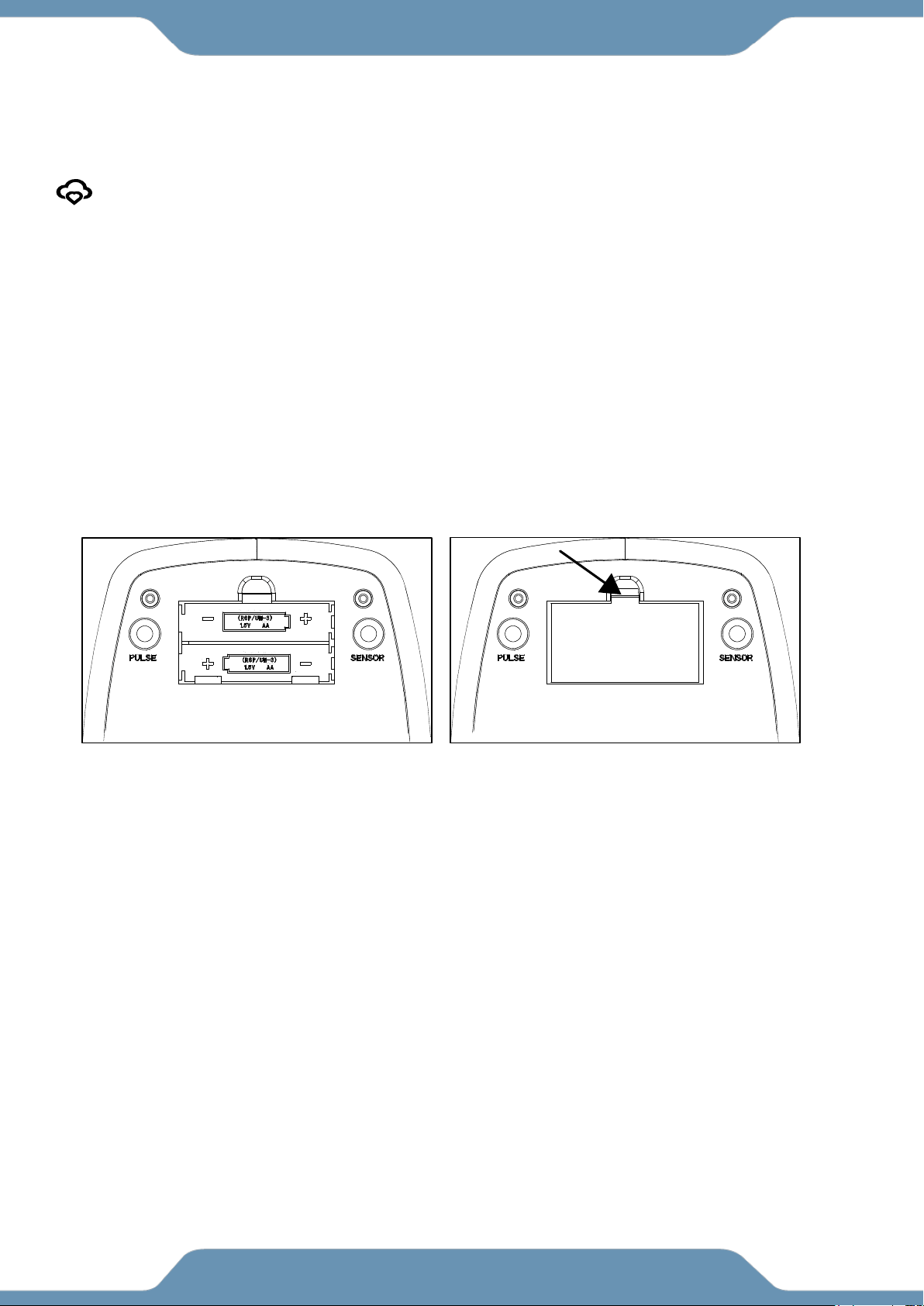
: The Mycloud Fitness logo will appear on the LCD when the APP is connected.
HOW TO INSTALL THE BATTERIES:
1. Remove the battery cover at the rear of computer.
2. Place two "SIZE-AA" batteries into the battery housing as shown in Fig. A.
3. Insure batteries are correctly positioned and battery springs are in proper
contact with batteries.
4. Re-install the battery cover, make sure to firmly press the battery clip into
the backside of the console as shown in Fig. B.
5. If the display is illegible or only partial legible, remove batteries and wait 15
seconds before reinstalling.
CONSOLE
21
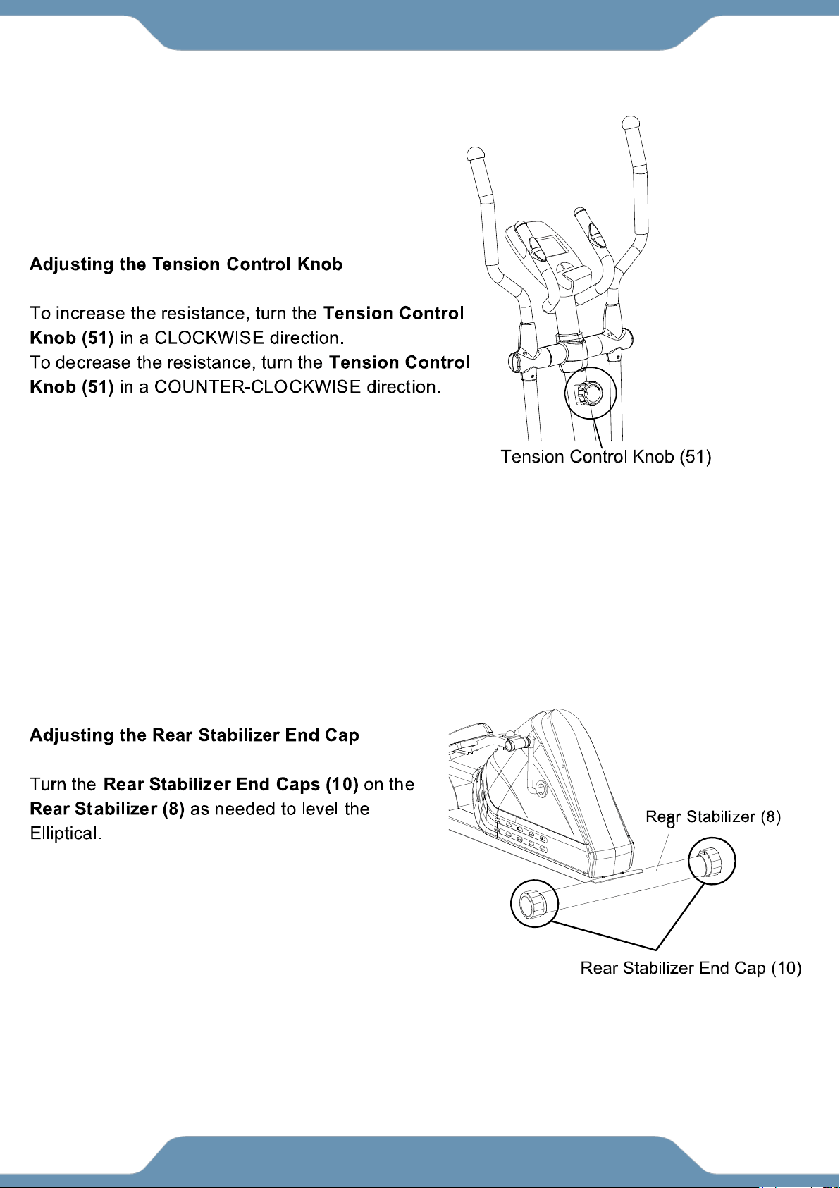
ADJUSTMENTS
22
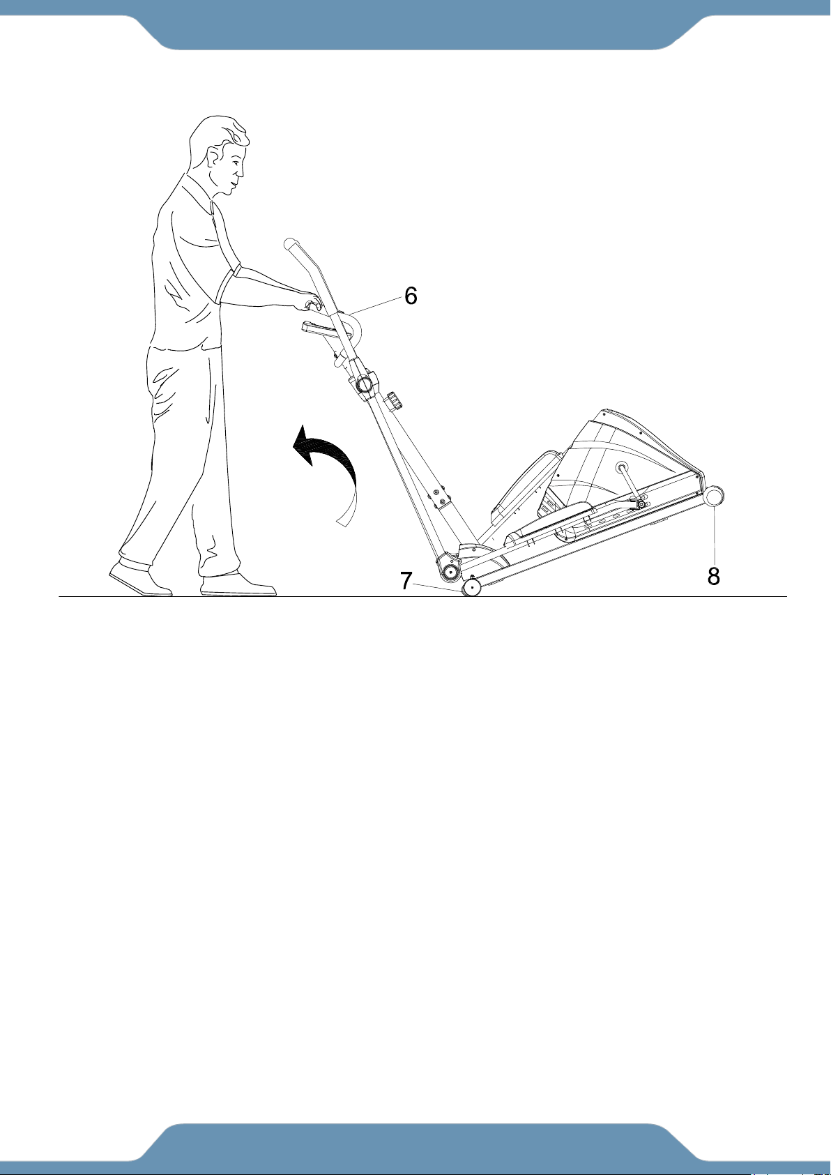
Transporting the Elliptical
Hold the Handlebar (6) and lift up the machine until the wheels on the Front
Stabilizer (7) make contact with the floor. Push or pull the unit to the desired
location, then gently lower the machine and Rear Stabilizer (8) until it makes
contact with the ground.
TRANSPORTING THE ELLIPTICAL

23
TROUBLESHOOTING & MAINTENANCE
TROUBLESHOOTING
PROBLEM: The elliptical wobbles when in use.
SOLUTION: Turn the Rear Stabilizer End Cap (10) on the Rear Stabilizer (8) as needed to level
the elliptical.
PROBLEM: The Console (53) does not turn on.
SOLUTION: Remove the Console (53) and verify that ALL wires that come from the
Console (53) are properly connected to the wires that come from the Front Post (5).
PROBLEM: There is no Pulse reading or there is erratic / inconsistent readings.
SOLUTION: Make sure that the Hand Pulse Wires (101) are securely connected to the Sensor
Wire comes from the Console (53).
SOLUTION: To ensure the pulse readout is more precise, always hold on to the
Hand Pulse Sensors (55) with two hands instead of just one.
SOLUTION: Avoid gripping the Hand Pulse Sensors (55) too tight. Try to maintain moderate
pressure while holding onto the Hand Pulse Sensors (55).
PROBLEM: The elliptical makes a squeaking noise when in use.
SOLUTION: Bolts may be loose on the elliptical. Inspect all bolts and tighten any that have become
loose over time.
MAINTENANCE
Cleaning
1. The elliptical can be cleaned with a soft cloth and mild detergent. Do not use abrasives or solvents
on plastic parts.
2. Wipe your perspiration off the elliptical after each use.
3. Be careful not get excessive moisture on the Console (53) as this might cause an electrical hazard
or electronics to fail.
4. Keep the elliptical, especially, the Console (53) out of direct sunlight to prevent screen damage.
5. Inspect all assembly bolts, nuts, and Screws on the machine for proper tightness every week.
Storage
Store the elliptical in in doors and in a clean and dry environment away from children.

24
WARRANTY
MANUFACTURER’S LIMITED WARRANTY
Paradigm Health & Wellness warrants to the original purchaser that this product is free from
defects in material and workmanship when used for the purpose intended, under the
conditions that it has been installed and operated in accordance with Paradigm’s Owner’s
Manual. Paradigm’s obligation under this warranty applies to the following:
COMPONENT LENGTH OF WARRANTY
Structural Frame 1 year For Home Use Only
All Other Components 90 days For Home Use Only
(computer display, electronics, upholstery, foam, ball bearings, pulleys, belts, cables, wires,
shocks, covers, tension, internal mechanism, wheels, pedals, knobs, accessories and
hardware)
Exclusions from Warranty Coverage:
Paradigm does not warrant against and is not responsible for, and no implied warranty shall be deemed to cover, any
product failure, product malfunction, or damages attributable to:
1. Improper installation and/or failure to abide by Paradigm’s installation guidelines;
2. Use of this product beyond normal home use, or in an application for which it was not designed;
3. Cosmetic items such as scratches, dents or discolorations;
4. Damage caused by normal wear and tear, vandalism, accidental or by animals;
5. Any act of Nature (such as fire, flooding, snow, ice, hurricane, earthquake, lightning or other natural disaster),
environmental condition (such as air pollution, mold, mildew, etc.), or staining from foreign substances (such as dirt,
grease, oil, etc.);
6. Normal weathering due to exposure to sunlight, weather and atmosphere which can cause colored surfaces to,
among other things, flake, chalk, or accumulate dirt or stains; or
7. Improper operation, alteration, handling, storage, abuse or neglect of the products.
Paradigm, using its sole discretion, will either repair or replace free of charge any part(s) proven to
be defective under normal home use. Any repair or replacement shall provide no new warranty
coverage, but shall retain only the remaining portion of the original product’s warranty. This
warranty is offered only to the original purchaser and is not transferable. Proof of original purchase
is required.
Ordering Replacement Parts
Replacement parts can be ordered by emailing our customer service department:
Open Monday thru Friday 8:00 AM - 5:00 PM (PST).
When ordering replacement parts please have the following information ready:
1. Owner’s Manual
2. Model Number
3. Description of Parts
4. Part Number
5. Date of Purchase

25
PARTS REQUEST FORM
Paradigm Health & Wellness, Inc.
EMAIL THIS FORM WITH YOUR RECEIPT OF PURCHASE TO
Service@paradigmhw.com *
NAME:_____________________________________________________________________________________
ADDRESS:__________________________________________________________________________________
CITY:________________________ STATE:_____________ ZIP:_______________________________________
TELEPHONE: (Day)______________________________________________________________________
(Night)_____________________________________________________________________
SERIAL#:___________________________________________________________________________________
MODEL#:___________________________________________________________________________________
PURCHASE DATE:___________________________________________________________________________
PLACE OF PURCHASE:_______________________________________________________________________
“YOUR ORDER WILL BE PROCESSED WITHIN 3 BUSINESS DAYS”
This form can also be faxed to #: 626-810-2166
PART #
DESCRIPTION
QTY