
IMPORTANT: Read all instructions carefully before using this product. Retain this
owner’s manual for future reference. The specifications of this product may vary
from this photo, subject to change without notice.
Desk Bike
OWNER’S MANUAL
7150.7-020918

PLEASE DO NOT RETURN THIS PRODUCT
TO THE STORE.
STOP. Contact customer service if you have any questions
regarding assembly or proper operation of the machine.
Email us at:
Service@paradigmhw.com
Or call us at:
1-844-641-7921
Hours:
8:00 am to 5:00 pm (PST)
Monday thru Friday

1
TABLE OF CONTENTS
SERVICE------------------------------------------------------------------------------- 2
LABEL PLACEMENT---------------------------------------------------------------- 3
IMPORTANT SAFETY GUIDELINES------------------------------------------- 4
OVERVIEW DRAWING------------------------------------------------------------- 6
PARTS LIST--------------------------------------------------------------------------- 7
HARDWARE & TOOLS PACK--------------------------------------------------- 9
ASSEMBLY---------------------------------------------------------------------------- 11
CONSOLE ---------------------------------------------------------------------------- 18
OPERATIONS & ADJUSTMENTS---------------------------------------------- 19
BATTERY INSTALLATION-------------------------------------------------------- 23
STORAGE----------------------------------------------------------------------------- 24
TRANSPORTION-------------------------------------------------------------------- 25
MAINTENANCE & TROUBLESHOOTING---------------------------------- 26
WARRANTY--------------------------------------------------------------------------- 27
PART REQUEST FORM----------------------------------------------------------- 28

2
SERVICE
SERVICE
IMPORTANT: FOR NORTH AMERICA ONLY
For damaged or defective product, questions, replacement parts or any other service
support, please contact our customer service department by the below methods:
For The Best Service, please Email:
service@paradigmhw.com
Response Time: 1-2 Business Days
Emailing us with the information above will be the best method to receive a response
during peak business hours
Website:
www.paradigmhw.com
Toll-Free:
1-844-641-7921
(8:00 AM - 5:00 PM Pacific Standard Time, Monday thru Friday)
Response time may vary via calling
Please have the following information ready when requesting for service:
Your name
Phone number
Model number
Serial number
Part number
Proof of Purchase
For damaged or defective product please contact our customer service before returning to
the store.
Paradigm Health & Wellness, Inc.
1189 Jellick Ave.
City of Industry, CA 91748, USA
3
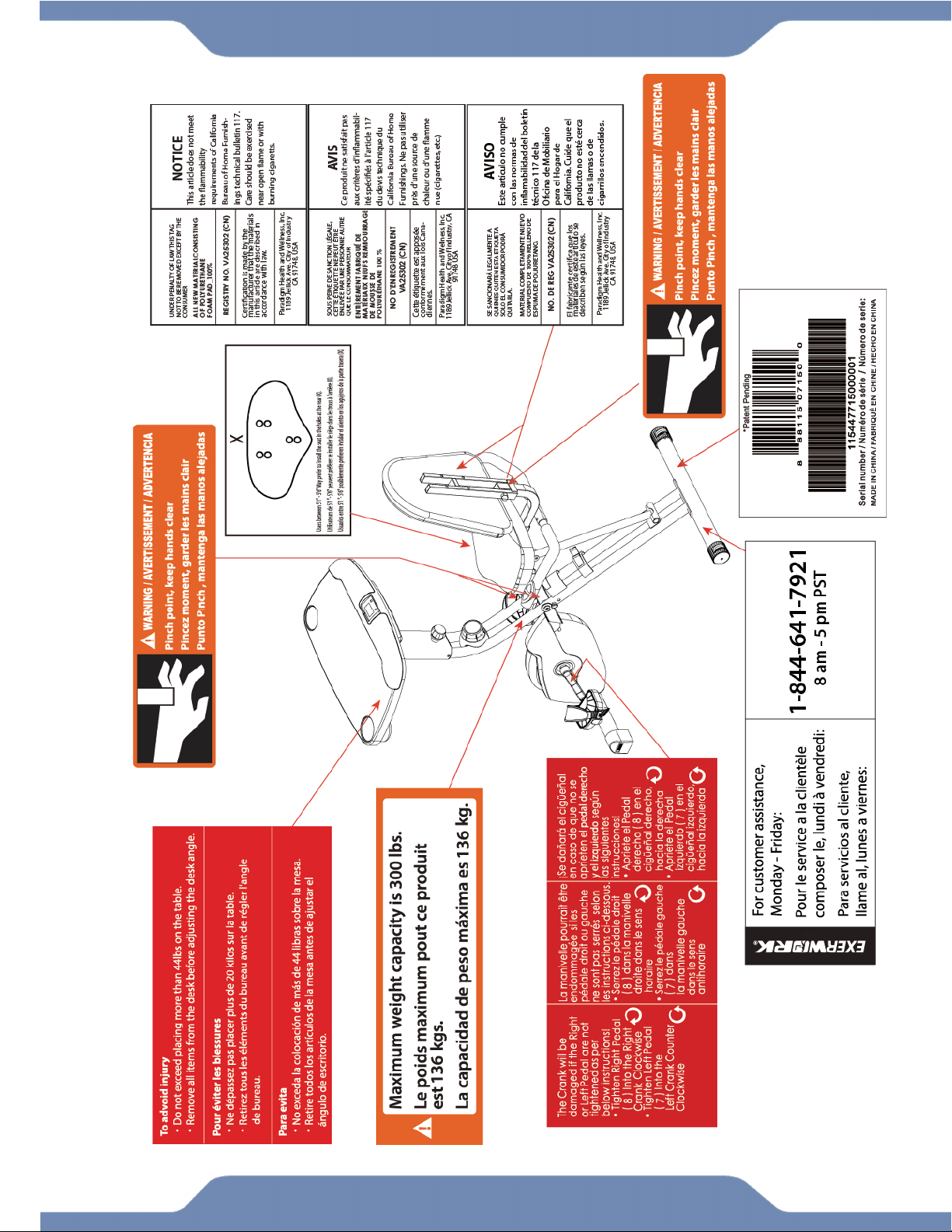
LABEL
PLACEMENT

4
IMPORTANT SAFETY GUIDELINES
Basic precautions should always be followed, including the following safety guidelines
when using this desk bike. Read all of the guidelines before using this desk bike.
1. Before exercising and to avoid injuring your muscles, it is highly recommended that you
perform warm-up exercises for each muscle group.
2. Make sure all the components are not damaged and are in working order before using. This
equipment should be placed on a stable, flat surface. Using a mat or similar, covering material
on the ground is recommended.
3. Wear proper fitness apparel when using this equipment. Do not wear loose clothing or
accessories that may get caught by any part of the equipment.
4. Make sure all the components are not damaged and are in working order before using this
equipment.
5. Remember to tighten the pedaling straps. Keep dry. Do not operate the equipment in wet or
moist condition.
6. Do not use the equipment outdoors. This equipment is for household use only.
7. Only perform maintenance or adjustments that are instructed in this manual. Should any
problems arise, discontinue usage of the equipment and consult with our customer service.
8. Only one person should be on the equipment at a time. Keep children and pets away from the
product at all times. This machine is designed for adults only.
9. Be careful to always hold onto the handlebars when you’re mounting and dismounting. Be
careful to have the pedals at their lowest point when stepping off.
10. Hold onto the handlebars and use both the pedals in tandem to ensure a smooth, effective
workout.
11. This product requires a minimum of 7 square feet around for safe operation.
12. If you feel any chest pains, nausea, dizziness, or shortness of breath, you should stop
exercising immediately, and consult your physician before continuing.
13. DO NOT pedal in reverse.
14. ASSEMBLE ALL HARDWARE IN THE ORDER THAT IS SHOWN IN THE ILLUSTRATIONS
WARNING: Before beginning any exercise program consult your physician. This is
especially important for the people who are over 35 years old or who have pre-existing health
problems.
WARNING: Risk of Personal Injury - Do not attempt to service the unit yourself.
Discontinue use and contact customer service.
CAUTION: Read all guidelines carefully before operating this product. Retain this
Owner’s Manual for future reference.

5
The product weighs more than 44 lbs. It is heavily
recommended that at least 2 persons assemble.
IMPORTANT SAFETY GUIDELINES
Do not use this equipment if you have any of the following conditions or ailments:
Pregnancy
Extreme obesity
Middle ear infection
Hiatus hernia or Ventral hernia
Glaucoma, retinal detachment or conjunctivitis
Use of anticoagulants including Aspirin in high doses.
Spinal injury, Cerebral Sclerosis, or acutely swollen joints
Heart or circulatory disorders for which you are being treated
High blood pressure, Hypertension, Recent stroke or Transient Ischemic attack
Bone weaknesses including Osteoporosis, Unhealed fractures, Modular pins, or surgically implanted
orthopedic supports.
Do not exceed the maximum rated weight (load):
The Maximum Weight Capacity for this product is 300lbs/136kgs.
Retain this owner’s manual and keep the original purchase receipt
for future reference.
SAVE THESE GUIDELINES
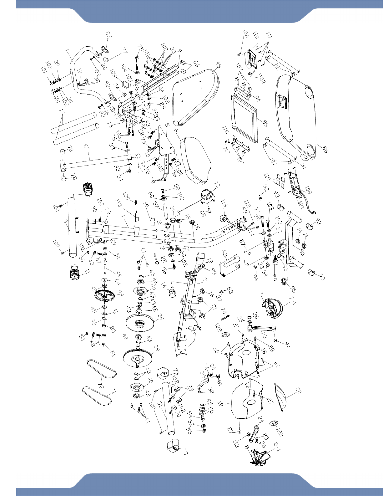
6
OVERVIEW DRAWING

7
PARTS LIST
No.
Description Qty
No. Description Qty
1 Rear Frame 1
36 Washer Ø6.2 2
2 Front Frame 1
37 Sensor with Wire 1
3 Rear Stabilizer 1 38 Flywheel Ø195 1
4 Handlebar 1
39 Belt Wheel with Crank Axle Ø155 1
5 Seat Post 1
40 Bearing Bracket 2
6 Seat 1 41 Wave Washer 1
7 Left Pedal 1 42 Bearing 6003RS 4
7-1
Left Pedal Strap 1
43 C-ring Ø17 6
8 Right Pedal 1
44 Belt Wheel with Crank Axle Ø150 1
8-1
Right Pedal Strap 1 45 Bearing 6000z 2
9 Backrest Frame 1 46 Axle Ø12.8x94L 1
10 Wire Plug 2
47 Eyebolt M6 2
11 Rear Stabilizer End Cap 2
48 Tension Bracket 2
12 Seat Post Plastic Bushing 1 49 Backrest 1
13 Tension Control Knob 1
50 Nylon Nut M6 2
14 Seat Adjustment Knob M16 1
51 Nut M10 2
15 Rear Supporting Tube 1 52 Washer Ø10.2xØ25 1
16 Oval Wire Plug 5 53 Wave Washer Ø17 1
17 Handrail Foam Grip 2
54 Idle Wheel Axle 1
18 Left Cover 1
55 Nylon Nut M10 1
19 Right Cover 1 56 Bearing 6902Z 2
20 Top Shroud 1 57 Axle 1
21 Round Plastic Bushing 6
58 Hexagon Socket Bolt M8*15 5
22 Safety Pin Ø10*110L 1
59 Rubber Cushion 1
23 Left Crank 1 60 Washer Ø8.2x Ø25x2.0t 2
24 Right Crank 1 61 Flat Phillips Head Screw M6x10 6
25 Flange Nut 2
62 Holder 1
26 Crank Cover 2 63 Round Phillips Head Screw
M4x10 1
27
Round Phillips Head Drilling
Screw M4x20 4
64 Plastic Washer 1
28 Round Phillips Head Tapping
Screw M4x20 5 65 C-ring Ø15 1
29 Hexagon Cap Nut M8 5 66 Square end cap 4
30 Curve Washer D Ø8.2 6
67 Rear Frame Support Tube 1
31 Front Stabilizer 1 68 Screw M5x20 1
32 C-ring Ø 10 2 69 Washer Ø5.2xØ18 2
33 Flat Washer Ø8.2 13
70 Spring 1
34 Nylon Nut M8 6
71 Belt 240J4 1
35 Magnet Bracket 1 72 Belt 230J3 1

8
No. Description Qty
No. Description Qty
73 Front Stabilizer End Cap 2
99 Connection Wire B 1
74 Spring Washer Ø 6.2 1 100 Drilling Screw M4x10 4
75 Hexagon Socket Bolt M8x80L 1 101 Hexagon Socket Bolt M8*45 6
76 Hexagon Socket Bolt M8x43L 1
102 Spring Washer Ø8.2 17
77 Handlebar End Cap Ø25.4 3
103 Hexagon Socket Bolt M8*25 1
78
Front Frame Support Tube End Cap
Ø22.2 2 104 Washer Ø25xØ8.2 2
79 Connection Wire A 2
105 Plastic Washer 2
80 Nut M6 1
106 Carriage Bolt M8*50 2
81 Screw M6x15 1 107 Drilling Screw M5x15 10
82 Hand Pulse Sensor 2 108 Battery Bracket 1
83
Countersunk Phillips Head Cap
Screw M4x20 2
109 Square end cap 30x30 1
84 Left Nylon Nut 9/16 1 110 Console 1
85 Nut M10 1
110A
Upper Console Wire 1
86 Bracket 1
110B
Upper Hand Sensor Wire 1
87 Desk Mount 1 111 Screw 4
88 Desk 1 112 Console Wire 1
89 Drawer 1
113 Tube Clip 1
90 Bracket 2
114 Flat Washer Ø10.2 1
91 Slide 2 115 Clip 4
92 Plastic Bushing 1 116 Nut M5 1
93 End cap 4
117 Screw M5 1
94 Desk Adjustment Knob 1 118 Right Nylon Nut 9/16 1
95 Slide Knob 1 119 Long Adjustment Knob M16 1
96 Phillips Panhead Bolt 1
120 Screw M4x12L 1
97 Hexagon Socket Bolt M8*58 1
121 Screw 4
98 Hand Pulse Wire 2 122 Crank Plug 2
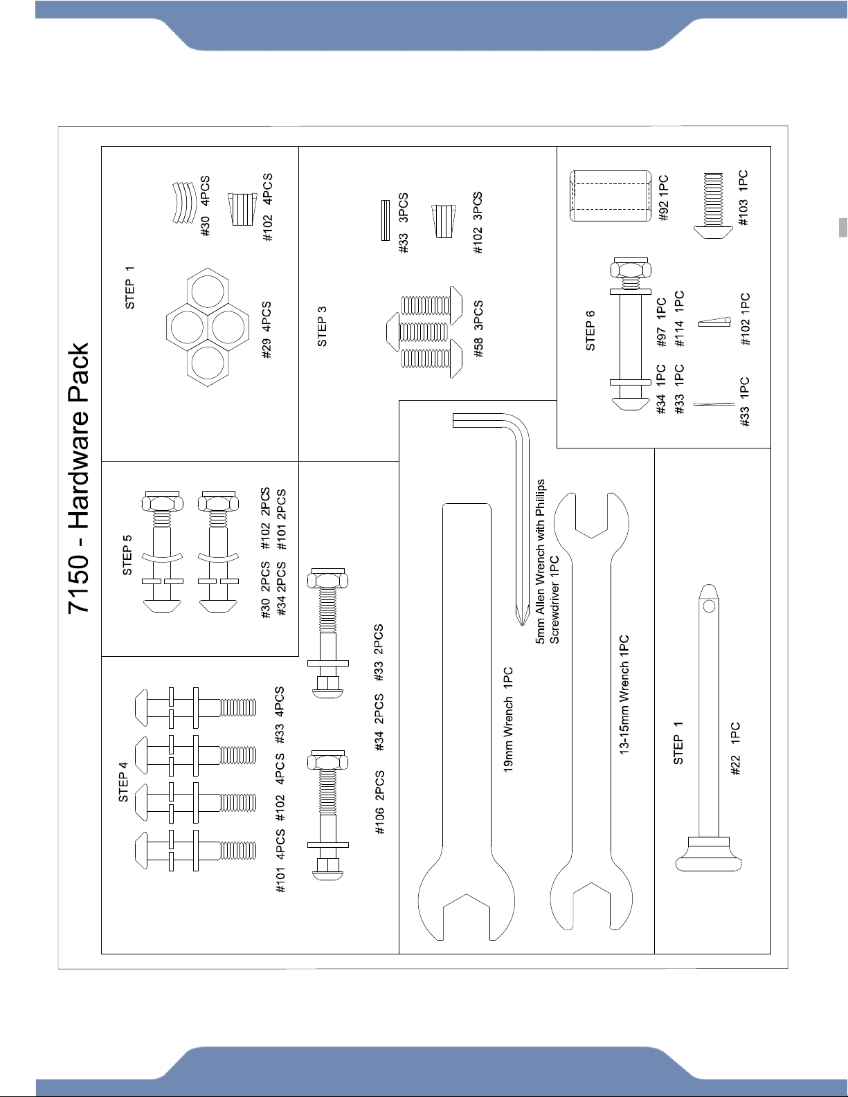
9
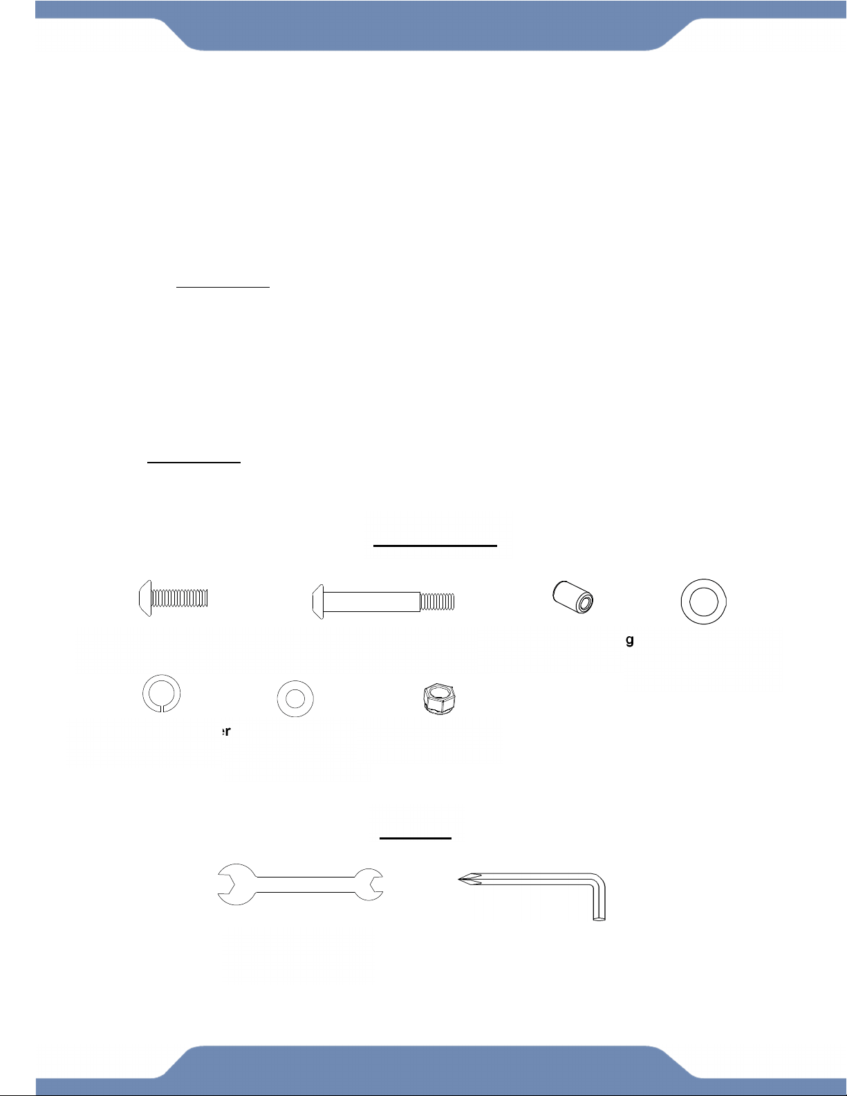
HARDWARE & TOOLS PACK

10
THIS PAGE IS INTENTIONALLY BLANK
11
TOOL
13-15mm Wrench
ASSEMBLY
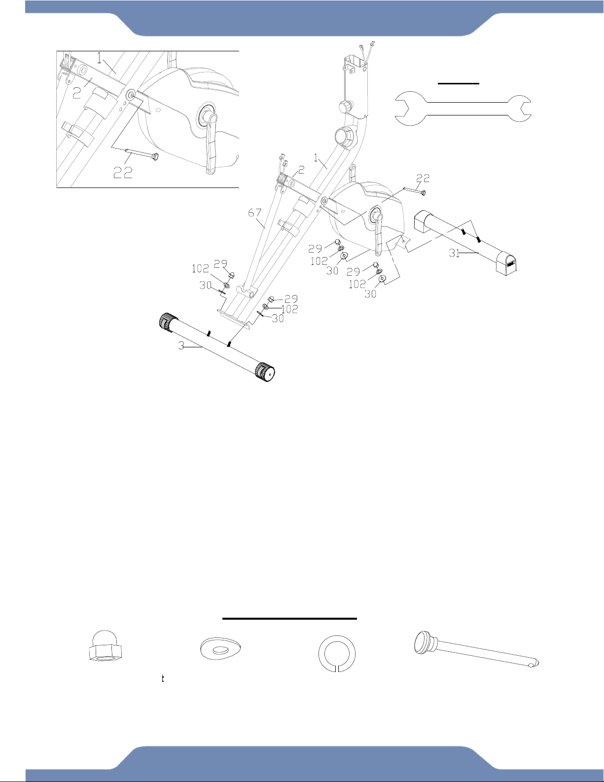
STEP 1
1A. Setting Up the Frames: Pull apart the Front Frame (2) and the Rear Frame (1). Rest the
Rear Frame Support Tube (67) into the hooked plate on the Rear Frame (1). Align the pin holes
where the Front Frame (2) and Rear Frame (1) intersect and insert the Safety Pin (22) into the
aligned holes. See Figure A. The aligned holes can be found by tracing the Safety Pin (22) in the
illustration.
1B. Installing the Front Stabilizer: Attach the Front Stabilizer (31) to the Front Frame (2) with
two Hexagon Cap Nuts (29), two Spring Washers (102), and two Curve Washers (30).Then
tighten the Hexagon Cap Nuts (29) using the 13-15mm Wrench provided.
1C. Installing The Rear Stabilizer: Attach the Rear Stabilizer (3) to the Rear Frame (1) with two
Hexagon Cap Nuts (29), two Spring Washers (102), and two Curve Washers (30). Then tighten
the Hexagon Cap Nuts (29) using the 13-15mm Wrench provided.
HARDWARE PACK
(29) Hexagon Cap Nut
4PCS
(102) Spring Washer
4PCS
(30) Curve Washer
4PCS
(22) Safety Pin
1PC
Figure A
12
ASSEMBLY
IMPORTANT:
Make sure the right pedal matches up with the right crank and the left
pedal matches up with the left crank. If matched incorrectly, the cranks
may become damaged or stripped.
IMPORTANT:
Screw the Right Pedal (8) into the Right Crank (24) in a
CLOCKWISE direction.
Screw the Left Pedal (7) into the Left Crank (23) in a
COUNTER-CLOCKWISE direction.
.
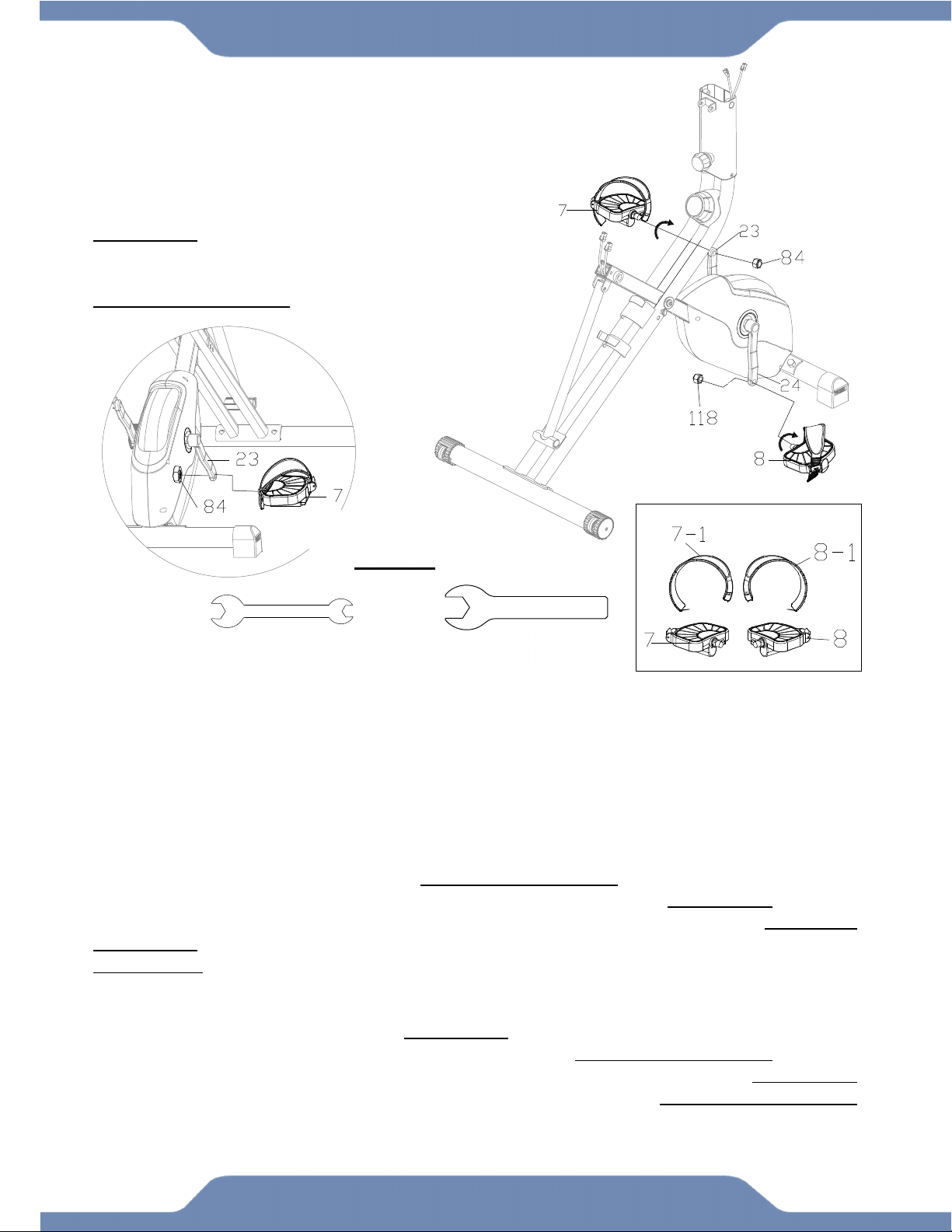
STEP 2
TIP: The Cranks, Pedals, Pedal Shafts and Pedal Straps are marked “R” for Right and “L” for Left.
2A. Instalilng the Pedal Straps: Remove the Left Nylon Nut (84) and Right Nylon Nut (118)
from the Left & Right Pedals (7,8). Install the Left & Right Pedal Straps (7-1, 8-1) on to the Left
& Right Pedals (7, 8). See Figure B.
2B. Installing the Left Pedal: Insert the Left Pedal (7) into the threaded hole in the Left Crank
(23). Turn the Left Pedal (7) by hand in a COUNTER-CLOCKWISE direction until snug. Attach the
Left Nylon Nut (84) onto the protruding Left Pedal (7) in a CLOCKWISE direction.
Simultaneously tighten the Left Pedal (7) using the 13-15mm Wrench by turning it COUNTER-
CLOCKWISE and tighten the Left Nylon Nut (84) with the Wrench 19mm provided in the
CLOCKWISE direction. See Figure C.
2C. Installing the Right Pedal: Insert the Right Pedal (8) into the threaded hole in the Right
Crank (24).Turn the shaft by hand in a CLOCKWISE direction until snug. Attach the Right Nylon
Nut (118) onto the protruding Right Pedal (8) in a COUNTER-CLOCKWISE direction.
Simultaneously tighten the Right Pedal (8) with the 13-15mm Wrench in the CLOCKWISE
direction and the Right Nylon Nut (118) with the 19mm Wrench with a COUNTER-CLOCKWISE
direction.
TOOLS
13-15mm Wrench 1 PC 19mm Wrench 1 PC
Figure C Figure B
13
ASSEMBLY
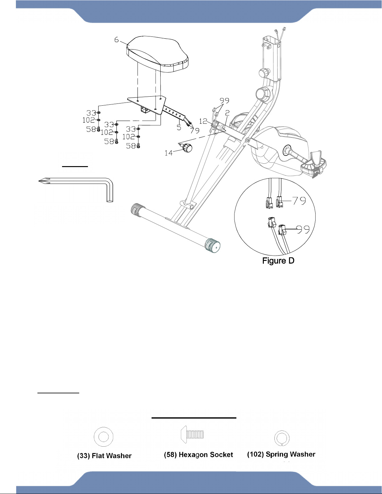
STEP 3
3A. Adjusting Seat Before Installing It: The Seat (6) has 2 sets of adjustment holes. It is
recommended that users between 5’1” – 5’6” use the holes towards the rear of the Seat (6). It is
recommended that users between 5’7” – 6’3” use the holes towards the front of the Seat (6).
3B. Installing The Seat To The Seat Post: Align the bolt holes on the underside of the Seat (6)
with the holes on the plate at the top of the Seat Post (5), then secure them together using three
Flat Washers (33), three Spring Washers (102), and three Hexagon Socket Bolts (58). Tighten
the Bolts (58) with the 5mm Allen Wrench provided.
3C. Installing The Seat Post & The Connection Wires: Connect the Connection Wire A (79)
from the Seat Post (5) to the Connection Wire B (99) from the Front Frame (2) as shown in
Figure D. Insert the Seat Post (5) into the Seat Post Plastic Bushing (12) while being careful to
insert the wires without pinching them. Install the Seat Adjustment Knob (14) by turning it
CLOCKWISE, making sure that the Seat Adjustment Knob (14) catches one of the height
adjustment holes of the Seat Post (5).
5mm Allen Wrench With
Phillips Screwdriver 1 PC
TOOL
(33) Flat Washer
3 PCS
(58) Hexagon Socket
3 PCS
(102) Spring Washer
3 PCS
HARDWARE PACK
14
ASSEMBLY
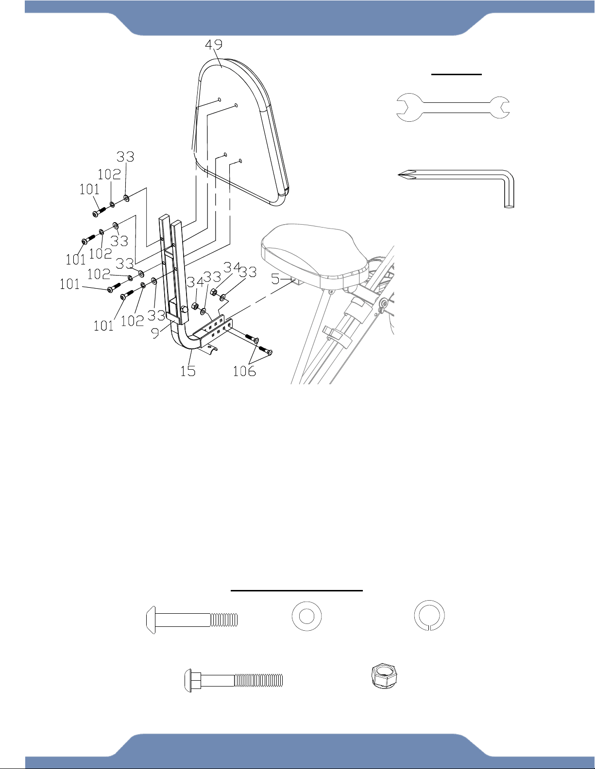
STEP 4
TIP: Refer to the Adjustments Pages 19-20 for more information on adjustments.
4A. Installing the Rear Support Tube to the Seat Post: Attach the Rear Support Tube (15)
onto the Seat Post (5) and choose two of the four holes on the Seat Post (5) to secure with using
two Carriage Bolts (106), two Flat Washers (33), two Nylon Nuts (34), and to secure the Rear
Support Tube (15) in place. Simultaneously tighten the Nylon Nuts (34) with the 13-15mm
Wrench.
4B. Installing the Backrest onto the Backrest Frame: Attach the Backrest (49) onto the
Backrest Frame (9) with four Hexagon Socket Bolts (101), four Spring Washers (102), and four
Flat Washers (33). Tighten the bolts with the 5mm Allen Wrench with Phillips Screwdriver
provided.
HARDWARE PACK
(33) Flat Washer
6 PCS
(101) Carriage Bolt
4 PCS
(102) Spring Washer
4 PCS
13-15mm Wrench
1 PC
5mm Allen Wrench
With Phillips Screwdriver
1 PC
TOOLS
(106) Carriage Bolt
2PCS
(34) Nylon Nut
2 PCS
15
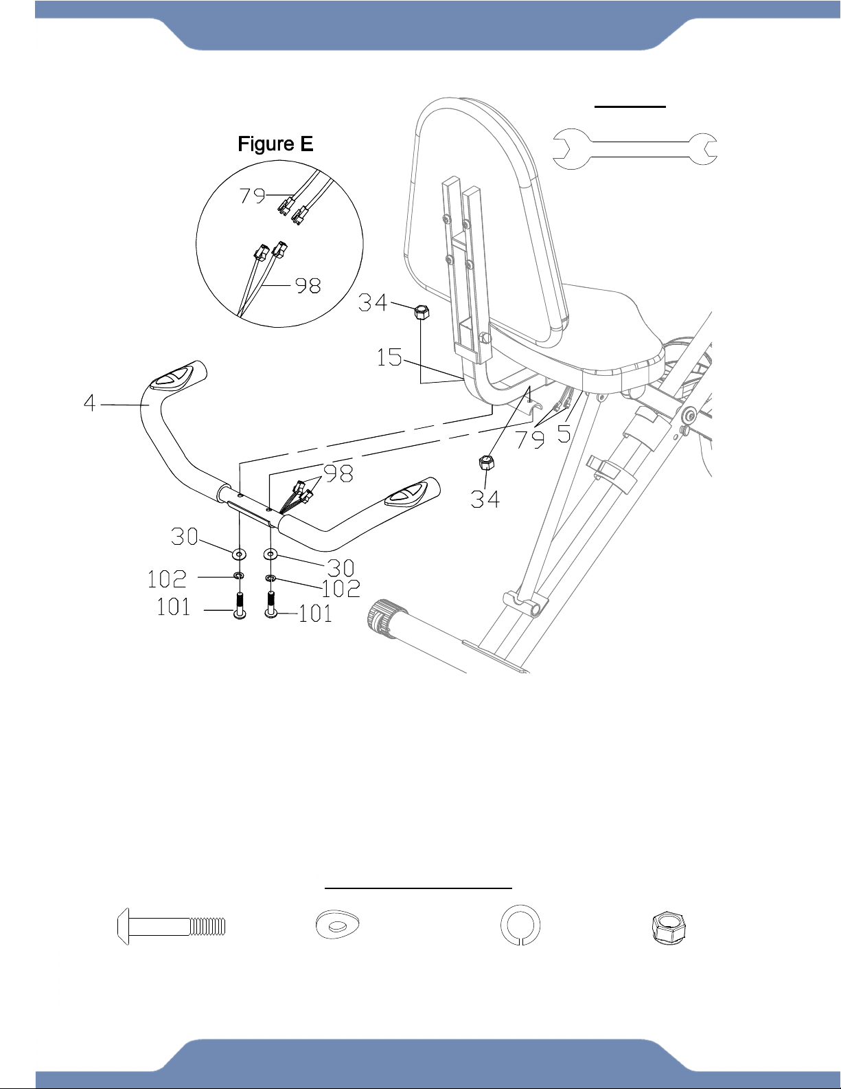
ASSEMBLY
TOOLS
13-15mm Wrench
1 PC
STEP 5
5A. Installing the Handlebars: Attach the Handlebar (4) onto the Rear Supporting Tube (15)
using two Curve Washers (30), two Spring Washers (102), and two Hexagon Socket Bolts
(101). Attach two Nylon Nuts (34) onto the protruding Carriage Bolts (101). Then tighten the
Nylon Nuts (34) with the 13-15mm Wrench provided.
5B. Connecting the Pulse Wires from the Handlebar: Connect the Hand Pulse Wire (98) from
the Handlebar (4) to the Connection Wire A (79) from the Seat Post (5) as shown in Figure E.
(101) Hexagon Socket Bolt
2PCS
(30) Curve Washer
2PCS
(102) Spring Washer
2 PCS
(34) Nylon Nut
2 PCS
HARDWARE PACK
16
ASSEMBLY
TOOLS
13-15mm Wrench
1 PC
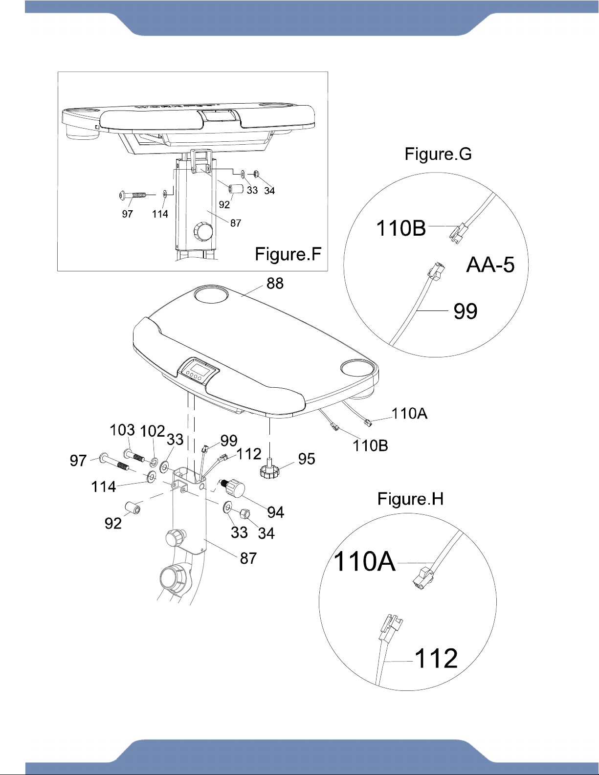
STEP 6
6A. Installing the Desk: Align the bolt holes of the U shaped bracket on the underside of the
Desk (88) with the holes on the bracket at the top of the Desk Mount (87) and insert one Plastic
Bushing (92) into the bracket of the Desk Mount (87) as shown in Figure F. Insert one Hexagon
Socket Bolt (97) one Flat Washer (114) through the brackets and Bushing (92). On the
protruding end of the Hexagon Socket Bolt (97) insert one Flat Washer (33) and one Nylon Nut
(34) and one Flat Washer (114). Tighten the Nylon Nut (34) with the 13-15mm Wrench provided.
6B. Installing the Pulse Wires: Insert the Slide Knob (95) onto the underside of the Desk (88)
by twisting it CLOCKWISE. Connect the Connection Wire B (99) from the Desk Mount (87) to
the Upper Hand Pulse Wire (110B). See Figure G. Connnect the Console Wire (112) to the
Upper Console Wire (110A). See Figure H.
6C. Installing the Desk: Set the Desk (88) flat on the Desk Mount (87) and assemble the Desk
(88) angle adjustment by inserting one Hexagon Socket Bolt (103) with one Spring Washer (102)
and one Flat Washer (33) into the left side of the Desk Mount (87). Tighten the Hexagon Socket
Bolt (103) with the 5mm Allen Wrench with Phillips Screwdriver provided. Insert the Desk
Adjustment Knob (94) into the hole on the right side of the Desk Mount (87) and tighten it by
turning it CLOCKWISE until snug.
(97) Hexagon Socket Bolt
1PC
(103) Hexagon Socket Bolt
1PC
(102) Spring Washer
1 PC
(33) Flat Washer
2 PCS
(34) Nylon Nut
1 PC
(92) Plastic Bushing
1PC
(114) Flat Washer
1 PC
HARDWARE
5mm Allen Wrench
With Phillips Screwdriver
1 PC
17
ASSEMBLY

18
CONSOLE
SPECIFICATIONS:
TIME --------------------------------------- 0:00-99:59 MIN:SEC
SPEED ------------------------------------ 0.0-999.9 ML/H
DISTANCE ------------------------------- 0.0-999.9 ML
CALORIE --------------------------------- 0.0-999.9 KCAL
ODOMETER ----------------------------- 0.0-999.9 ML
PULSE ------------------------------------ 40-240 BEATS/MIN
CONSOLE FUNTIONS:
MODE: Press the “MODE” button to select between,
SCAN,SPEED,DISTANCE,TIME,ODOMETER,CALORIES, and PULSE.
AUTO ON/OFF: The console will automatically turn on when pedaling begins. The console will
automatically turn off after 4 minutes of inactivity.
SCAN: Press the “MODE” button until the arrow (◄) points to “SCAN”. The console will
automatically scan the workout statistics of TIME, ODOMETER, CALORIE, PULSE, SPEED, and
DISTANCE, every 6 seconds.
TIME: Press the “MODE” button until the arrow (◄) points to “TIME”. The console will display the
total time exercised in minutes and seconds. The console automatically counts up from 0:00 to
99:59 in one second intervals.
SPEED: Press the “MODE” button until the arrow (◄) points to “SPEED”. The console will display
your current workout speed in miles per hour.
DISTANCE: Press the “MODE” button until the arrow (◄) points to “DIST”. The console will
display the distance traveled during each workout up to a maximum of 999.9 miles.
CALORIE: Press the “MODE” button until the arrow (►) points to “CAL”. The console will estimate
the cumulative calories burned during a workout. The console will count up from 0.0 to 999.9
calories.
ODOMETER: Press the “MODE” button until the arrow (►) points to “ODO”. The console will
display the recorded total distance of all workout sessions, up to a maximum of 999.9 miles. When
reseting the console, the ODOMETER values will not reset to zero. If the batteries are removed
from the console, the ODOMETER values will reset to zero.
PULSE: Press the “MODE” button until the console displays “P”. During the workout, hold onto the
Hand Pulse Sensors and the console will display your current heart rate in beats per minute. Hold
the Hand Pulse Sensors with both hands for a more accurate reading.
RESET: Hold this button for 4 seconds to reset all values from the console, Except ODOMETER.
HOW TO INSTALL THE BATTERIES:
1. Remove the battery cover on the underside of the Desk (88).
2. Place two "SIZE-AAA" batteries into the battery housing.
3. Insure the batteries are correctly positioned and the battery springs are in proper contact
with the batteries.
4. Re-install the battery cover.
5. If the display is illegible or only partially legible, remove the batteries and wait 15 seconds
before reinstalling.
19
OPERATIONS & ADJUSTMENTS
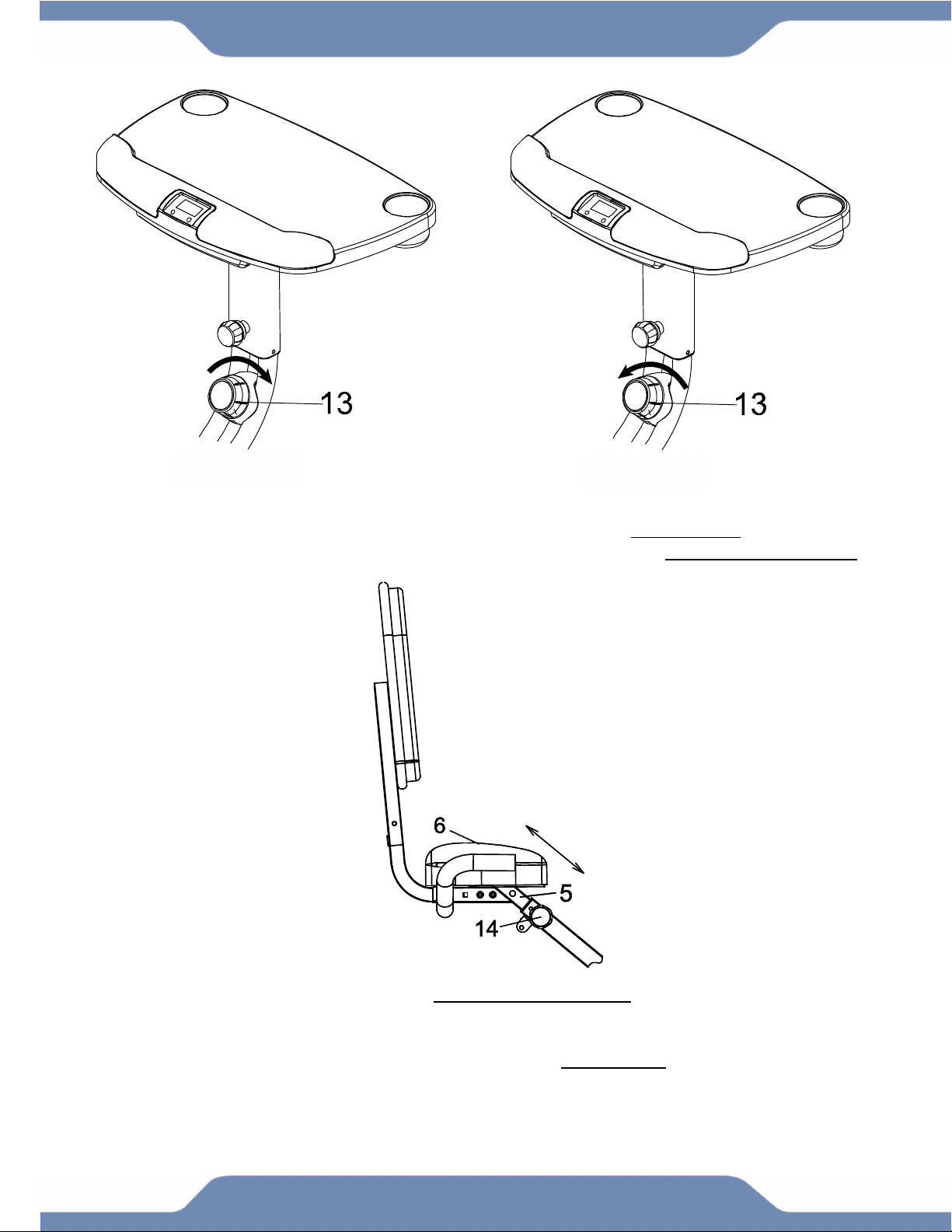
ADJUSTING THE TENSION CONTROL KNOB
To increase the resistance, turn the Tension Control Knob (13) in a CLOCKWISE direction.
To decrease the resistance, turn the Tension Control Knob (13) in a COUNTERCLOCKWISE
direction.
ADJUSTING THE SEAT HEIGHT
Turn the seat Adjustment Knob (14) in a COUNTER-CLOCKWISE direction and pull to release
the Seat Post (5). Slide the Seat Post (5) to the desired position and lock the Seat Post (5) in
place by allowing the Adjustment Knob (14) to “POP” into a height adjustment hole on the Seat
Post (5). Then tighten the Seat Adjustment Knob (14) in a CLOCKWISE direction.
NOTE: Do NOT exceed the MAX line on the seat post when adjusting the height of the Seat Post
(5).
INCREASE DECREASE
20
OPERATIONS & ADJUSTMENTS
ADJUSTING THE BACKREST
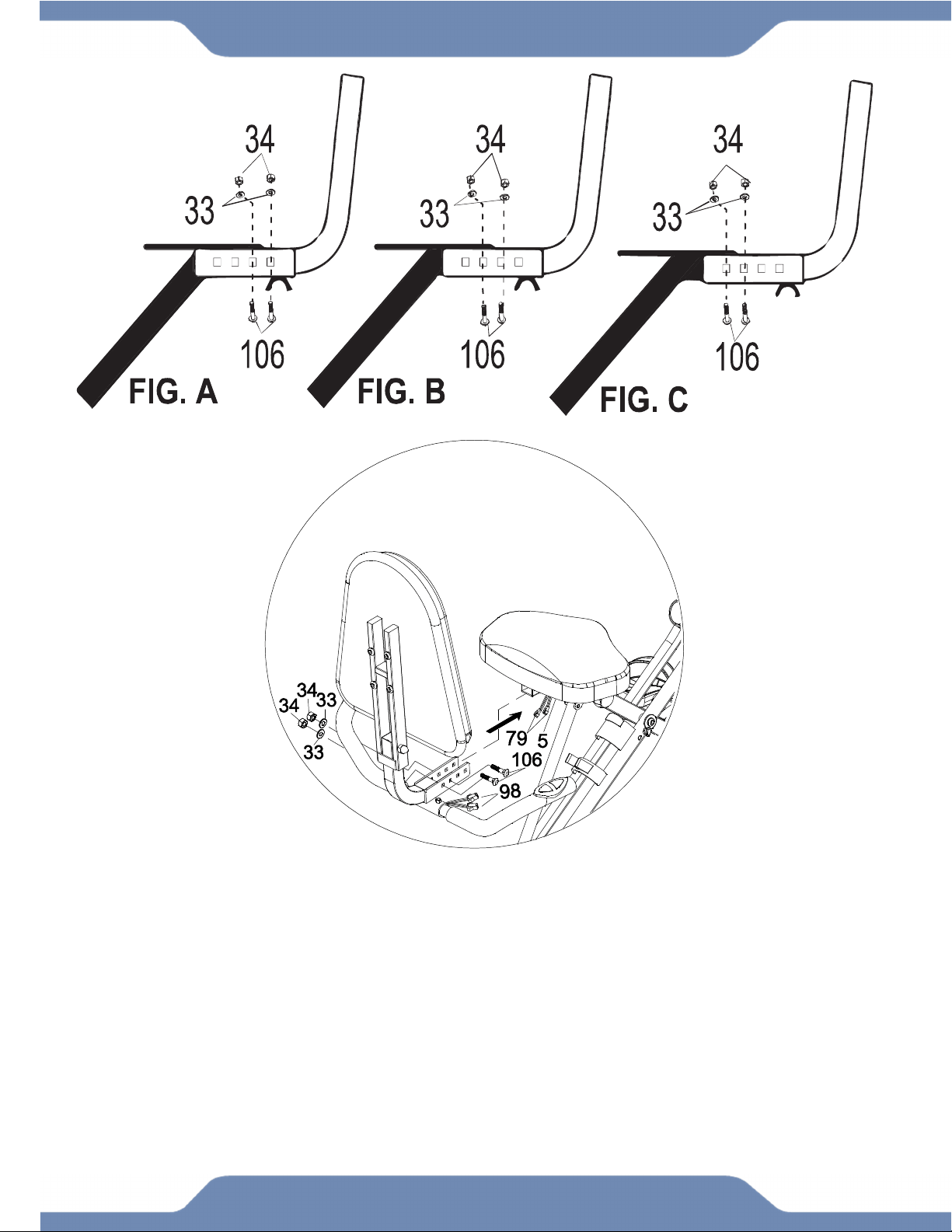
The Rear Supporting Tube (15) can be adjusted between 3 different positions:
1. Users between the height of 5’1” and 5’3” may want to use position 1, as shown in FIG. A.
2. Users between the height of 5’4” to 5’11” may want to use position 2 as shown in FIG. B.
3. Users between the height of 6’ to 6’3” may want to use position 3 as shown in FIG. C.
Carefully disconnect the Connection Wires A (79) from the Hand Pulse Wires (98). Once a
position is selected, install two Carriage Bolts (106), two Flat Washers (33), and two Nylon Nuts
(34). Tighten the Nylon Nuts (34) using the 13-15mm Wrench provided. Then reconnect the
Connection Wires A (79) and Hand Pulse Wires (98).
21
OPERATIONS & ADJUSTMENTS
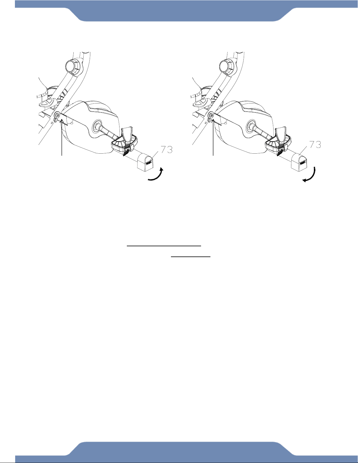
LEVELING THE MACHINE
If you experience a “wobble” while exercising, do the following:
Make sure the Front Stabilizer End Caps (73) are all in contact with the floor. Turn the Front
Stabilizer End Caps (73) in a COUNTER-CLOCKWISE direction to RAISE the Front Frame (2).
Turn the Front Stabilizer End Caps (73) in a CLOCKWISE direction to LOWER the Front Frame
(2). Do this as needed to level the machine.
2
2
22
OPERATIONS & ADJUSTMENTS
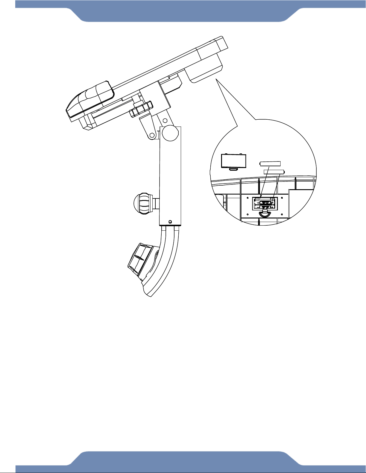
ADJUSTING THE DESK ANGLE
1. Loosen the Desk Adjustment Knob (94) by turning it in a COUNTER-CLOCKWISE
direction.
2. Pull the Desk Adjustment Knob (94) out to disengage the pin.
3. Tilt the Desk (88) to one of the three available positions shown above.
4. Release the Desk Adjustment Knob (94) to allow the pin to catch an angle position
hole, and then turn the Desk Adjustment Knob (94) clockwise to tighten.
WARNING: Clear the Desk (88) prior to repositioning it.
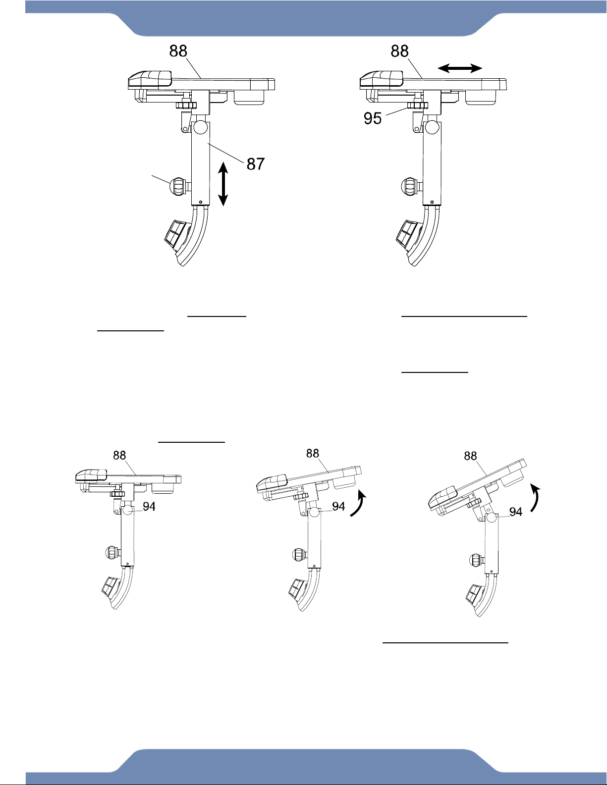
ADJUSTING THE DESK HEIGHT
1. Loosen the Long Adjustment Knob
(119) by turning it COUNTER-
CLOCKWISE.
2. Pull the Long Adjustment Knob
(119) to disengage the pin.
3. Shift the Desk Mount (87) up or
down to the desired position.
4. Release the Long Adjustment Knob
(119) to allow the pin to catch, and
then turn the Long Adjustment
Knob (119) CLOCKWISE to tighten.
ADJUSTING THE DESK RANGE
1. Loosen the Slide Knob (95) by
turning it COUNTER-CLOCKWISE.
2. Shift the Desk (88) forward or
backwards to the desired position.
3. Tighten the Slide Knob (95) by
turning it CLOCKWISE to lock the
Desk (88) in place.
0° 16° 33°
119
23
BATTERY INSTALLATION
HOW TO INSTALL THE BATTERIES:
1. Remove the battery cover on the back of the computer.
2. Place two "SIZE-AAA" batteries into the battery housing.
3. Ensure that the batteries are correctly positioned and that the battery springs are in proper
contact with batteries.
4. Re-install the battery cover.
24
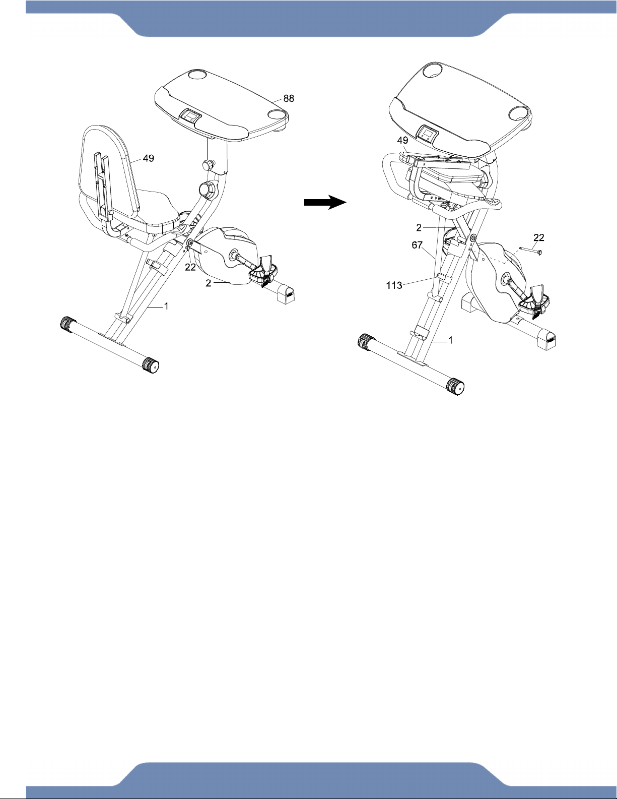
STORAGE
For your convenience, the bike can be folded up for storage when NOT in use.
1. Angle the Desk (88) to its lowest position. Refer to the Operations & Adjustments Page 22.
2. Slide the Desk (88) to its furthest forward position.
3. Remove the Safety Pin (22).
4. Push the Rear and Front Frames (1, 2) together.
5. Swing the Backrest (49) down flat against the Desk (88).
6. Align the Storage pin holes on the Rear and Front Frames (1, 2), and insert the Safety Pin
(22) into the lower pin hole to keep both sides of the frame in place.
7. Attach the Rear Frame Support Tube (67) onto the Tube Clip (113).
25
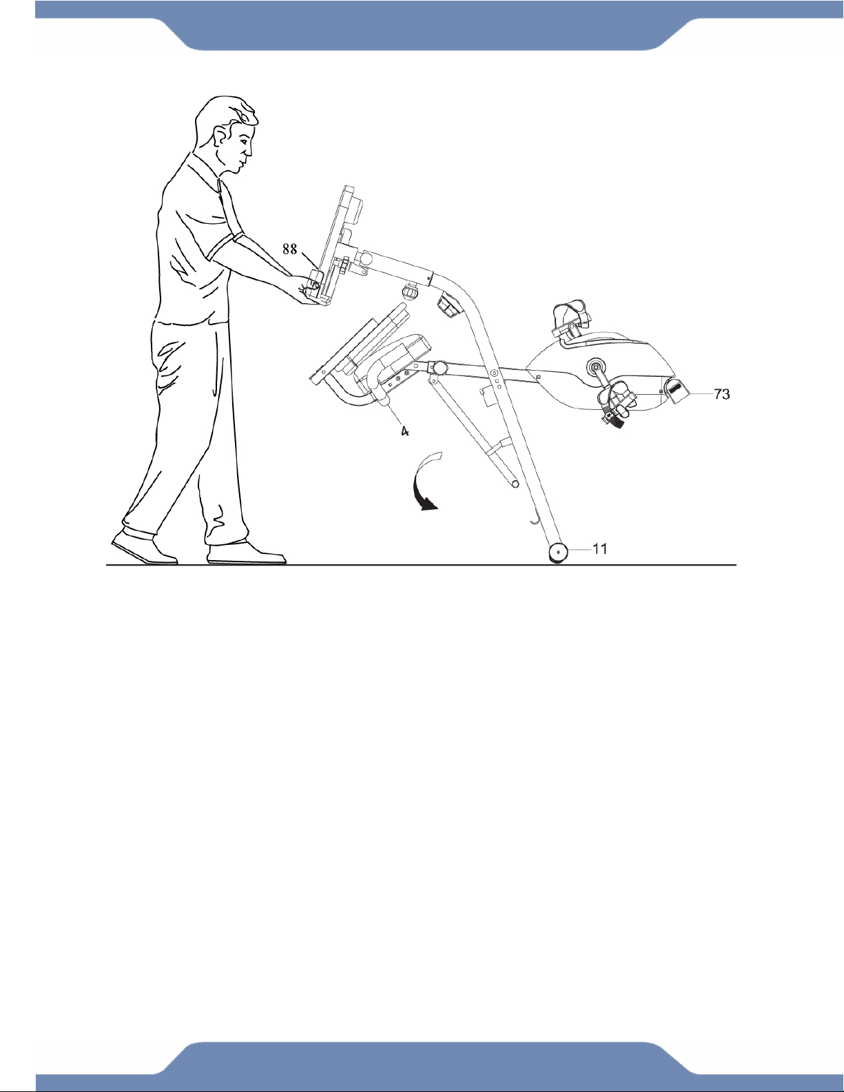
TRANSPORTATION
TRANSPORTING THE BIKE
1. Adjust the Bike to Storage Mode, see Operations & Adjustments page 24.
2. Hold onto the Desk (88) and tilt the bike onto to the wheels of the Rear Stabilizer End
Caps (11).
3. Carefully move the bike to the desired location.
4. Gently lower the bike until the Front Stabilizer End Caps (73) touches the floor.

26
MAINTENANCE & TROUBLESHOOTING
MAINTENANCE
Cleaning
The bike can be cleaned with a soft cloth and a mild detergent. Do not use abrasives or solvents
on the plastic parts. Be sure to wipe your perspiration off the bike after each use. Be careful to not
get excessive moisture on the console display panel as this may cause an electrical hazard or the
electronics to fail. Keep the bike, specifically the console, out of direct sunlight to prevent screen
damage. Inspect all of the assembly bolts and the pedals on the machine for proper tightness
every week.
Storage
Store the bike in a clean and dry environment away from pets and children.
TROUBLESHOOTING
PROBLEM: There is no display on the console.
SOLUTION: Check if the batteries are correctly positioned and the battery springs are in proper
contact with the batteries.
SOLUTION: The batteries in the console may be dead. Install new batteries.
PROBLEM: There is no heart rate reading or it is erratic and inconsistent.
SOLUTION: Make sure that the wire connections for the hand pulse sensors are connected and
connected correctly.
SOLUTION: To ensure the pulse readout is accurate, always hold on to the handlebar grip
sensors with both hands.
SOLUTION: Try to maintain moderate pressure while holding onto the hand pulse sensors. Avoid
gripping the hand pulse sensors too tightly as this may cause your pulse to be read incorrectly.
PROBLEM: The bike makes a squeaking noise when in use.
SOLUTION: The bolts and nuts may be loose on the bike. Inspect all of the bolts and tighten any
loose bolts and nuts.
SOLUTION: Loosen and then retighten the Seat Adjustment Knobs in case there is build-up on
the threads of the knobs which might cause the squeaky noises.
If you need further assistance,
contact our Customer Service.

27
WARRANTY
MANUFACTURER’S LIMITED WARRANTY
Paradigm Health & Wellness warrants to the original purchaser that this product is free
from defects in material and workmanship when used for the purpose intended, under the
conditions that it has been installed and operated in accordance with Paradigm’s Owner’s
Manual. Paradigm’s obligation under this warranty applies to the following:
COMPONENT LENGTH OF WARRANTY
Structural Frame 3 years For Home Use Only
All Other Components 90 days For Home Use Only
(computer display, electronics, upholstery, foam, ball bearings, pulleys, belts, cables, wires, shocks, covers, tension,
internal mechanism, wheels, pedals, knobs, accessories and hardware)
Exclusions from Warranty Coverage:
Paradigm does not warrant against and is not responsible for, and no implied warranty shall be deemed to cover, any
product failure, product malfunction, or damages attributable to:
1. Improper installation and/or failure to abide by Paradigm’s installation guidelines;
2. Use of this product beyond normal home use, or in an application for which it was not designed;
3. Cosmetic items such as scratches, dents or discolorations;
4. Damage caused by normal wear and tear, vandalism, accidental or by animals;
5. Any act of Nature (such as fire, flooding, snow, ice, hurricane, earthquake, lightning or other natural disaster),
environmental condition (such as air pollution, mold, mildew, etc.), or staining from foreign substances (such as dirt,
grease, oil, etc.);
6. Normal weathering due to exposure to sunlight, weather and atmosphere which can cause colored surfaces to,
among other things, flake, chalk, accumulate dirt or stains.
7. Improper operation, alteration, handling, storage, abuse or neglect of the products.
Paradigm, using its sole discretion, will either repair or replace free of charge any part(s)
proven to be defective under normal home use. Any repair or replacement shall provide no
new warranty coverage, but shall retain only the remaining portion of the original product’s
warranty. This warranty is offered only to the original purchaser and is not transferable.
Proof of original purchase is required.
Ordering Replacement Parts
Replacement parts can be ordered by emailing our customer service department:
Service@paradigmhw.com
Open Monday thru Friday 8:00 AM - 5:00 PM (PST).
When ordering replacement parts please have the following information ready:
1. Owner’s Manual
2. Model Number
3. Description of Parts
4. Part Number
5. Date of Purchase

28
PARTS REQUEST FORM
Paradigm Health & Wellness, Inc.
EMAIL THIS FORM WITH YOUR RECEIPT OF PURCHASE TO
Service@paradigmhw.com
NAME:______________________________________________________________________
ADDRESS:__________________________________________________________________
CITY:________________________ STATE:_____________
ZIP:________________________
TELEPHONE: (Day)_______________________________________________________
(Night)______________________________________________________
SERIAL#:____________________________________________________________________
MODEL#:____________________________________________________________________
PURCHASE DATE:____________________________________________________________
PLACE OF PURCHASE:_______________________________________________________
“YOUR ORDER WILL BE PROCESSED WITHIN 3 BUSINESS DAYS”
*This form can also be faxed to #: 626-810-2166
PART # DESCRIPTION QTY


