
IMPORTANT: Read all instructions carefully before using this product. Retain this
owner’s manual for future reference. The specifications of this product may vary
from this photo, subject to change without notice.
Desk Recumbent Bike
OWNER’S MANUAL
7170.4-050120


1
TABLE OF CONTENTS
SERVICE------------------------------------------------------------------------------- 2
LABEL PLACEMENT---------------------------------------------------------------- 3
IMPORTANT SAFETY GUIDELINES------------------------------------------- 4
OVERVIEW DRAWING------------------------------------------------------------- 6
PARTS LIST--------------------------------------------------------------------------- 8
HARDWARE & TOOLS PACK--------------------------------------------------- 10
ASSEMBLY---------------------------------------------------------------------------- 11
CONSOLE ---------------------------------------------------------------------------- 18
OPERATIONS & ADJUSTMENTS---------------------------------------------- 19
BATTERY INSTALLATION-------------------------------------------------------- 23
TRANSPORTION-------------------------------------------------------------------- 24
MAINTENANCE & TROUBLESHOOTING---------------------------------- 25
WARRANTY--------------------------------------------------------------------------- 26
PART REQUEST FORM----------------------------------------------------------- 27

2
SERVICE
SERVICE
IMPORTANT: FOR NORTH AMERICA ONLY
For damaged or defective product, questions, replacement parts or any other service
support, please contact our customer service department by the below methods:
For The Best Service, please Email:
Response Time: 1-2 Business Days
Emailing us with the information above will be the best method to receive a response
during peak business hours
Website:
www.paradigmhw.com
Toll-Free:
1-844-641-7921
(8:00 AM - 5:00 PM Pacific Standard Time, Monday thru Friday)
Response time may vary via calling
Please have the following information ready when requesting for service:
Your name
Phone number
Model number
Serial number
Part number
Proof of Purchase
For damaged or defective product please contact our customer service before returning to
the store.
Paradigm Health & Wellness, Inc.
1189 Jellick Ave.
City of Industry, CA 91748, USA
3
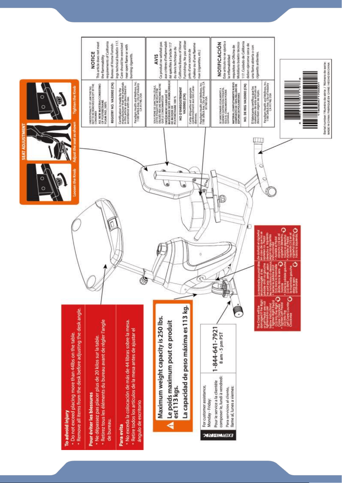
LABEL PLACEMENT

4
IMPORTANT SAFETY GUIDELINES
Basic precautions should always be followed, including the following safety guidelines
when using this desk bike. Read all of the guidelines before using this desk bike.
1. Before exercising and to avoid injuring your muscles, it is highly recommended that you
perform warm-up exercises for each muscle group.
2. Make sure all the components are not damaged and are in working order before using. This
equipment should be placed on a stable, flat surface. Using a mat or similar, covering material
on the ground is recommended.
3. Wear proper fitness apparel when using this equipment. Do not wear loose clothing or
accessories that may get caught by any part of the equipment.
4. Make sure all the components are not damaged and are in working order before using this
equipment.
5. Remember to tighten the pedaling straps. Keep dry. Do not operate the equipment in wet or
6. moist condition.
7. Do not use the equipment outdoors. This equipment is for household use only.
8. Only perform maintenance or adjustments that are instructed in this manual. Should any
problems arise, discontinue usage of the equipment and consult with our customer service.
9. Only one person should be on the equipment at a time. Keep children and pets away from the
product at all times. This machine is designed for adults only.
10. Be careful to always hold onto the handlebars when you’re mounting and dismounting. Be
careful to have the pedals at their lowest point when stepping off.
11. Hold onto the handlebars and use both the pedals in tandem to ensure a smooth, effective
workout.
12. This product requires a minimum of 7 square feet around for safe operation.
13. If you feel any chest pains, nausea, dizziness, or shortness of breath, you should stop
exercising immediately, and consult your physician before continuing.
14. DO NOT pedal in reverse.
15. ASSEMBLE ALL HARDWARE IN THE ORDER THAT IS SHOWN IN THE ILLUSTRATIONS
WARNING: Before beginning any exercise program consult your physician. This is
especially important for the people who are over 35 years old or who have pre-existing health
problems.
WARNING: Risk of Personal Injury - Do not attempt to service the unit yourself.
Discontinue use and contact customer service.
CAUTION: Read all guidelines carefully before operating this product. Retain this
Owner’s Manual for future reference.
!
!
!

5
The product weighs more than 44 lbs. It is heavily
recommended that at least 2 persons assemble.
IMPORTANT SAFETY GUIDELINES
Do not use this equipment if you have any of the following conditions or ailments:
Pregnancy
Extreme obesity
Middle ear infection
Hiatus hernia or Ventral hernia
Glaucoma, retinal detachment or conjunctivitis
Use of anticoagulants including Aspirin in high doses.
Spinal injury, Cerebral Sclerosis, or acutely swollen joints
Heart or circulatory disorders for which you are being treated
High blood pressure, Hypertension, Recent stroke or Transient Ischemic attack
Bone weaknesses including Osteoporosis, Unhealed fractures, Modular pins, or surgically implanted
orthopedic supports.
Do not exceed the maximum rated weight (load):
The Maximum Weight Capacity for this product is 250lbs/113kgs.
Retain this owner’s manual and keep the original purchase receipt
for future reference.
SAVE THESE GUIDELINES

6
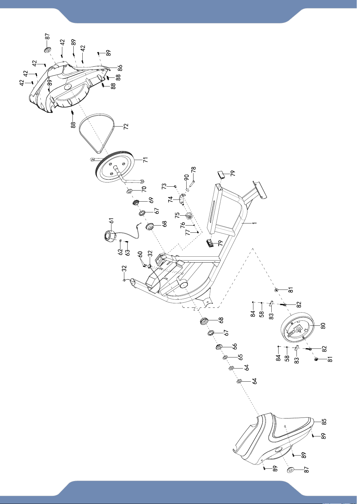
OVERVIEW DRAWING
7
OVERVIEW DRAWING

8
PARTS LIST
No.
Description
Qty
No.
Description
Qty
1
Main Frame
1
32
Sensor Wire W=650mm
1
2
Front Stabilizer
1
33
Left Pedal
1
3
Rear Stabilizer
1
34
Left Pedal Strap
1
4
Left Handlebar
1
35
Right Pedal
1
5
Right Handlebar
1
36
Right Pedal Strap
1
6
Seat Bracket
1
37
Carraige Bolt M10*65
4
7
Backrest Frame
1
38
Curved WasherФ10
4
8
Front Post
1
39
Spring Washer Ф10
4
9
Desk Post
1
40
Cap Nut M10
4
10
Left Adjustable Post
1
41
Front Stabilizer End CAP
2
11
Right Adjustable Post
1
42
Self-Tapping Screw ST4.2*20
7
12
Desk Sliding Tube
2
43
Rear Stabilizer End Cap
2
13
Desk
1
44
Hex NutM8
1
14
Console
1
45
Adjustable Levler
1
14A
Console Wire A
1
46
Plastic Pad
1
15
Console Wire BW=750mm
1
47
Seat Bracket
1
16
Hex Bolt M6*10
1
48
Wave Washer Ф10
1
17
Hex Bolt M8*55
5
49
Flat Washer Ф10
1
18
Flat Washer Ф8
11
50
Round Knob M10
1
19
Nylon Nut M8
5
51
Foam Grip
2
20
Hex Bolt M8*20
1
52
Handlebar End Cap
2
21
Desk Post End Cap
2
53
Seat
1
22
Self-Tapping Phillips Screw
ST5*15
4
54
Backrest
1
23
Bushing
8
55
Sqaure End Cap
2
24
Adjustable Post Knob M8*20
2
56
Pin
1
25
Adjustable Post Cover
2
57
Flat Washer Ф6
8
26
Plastic Bracket
2
58
Spring Washer Ф6
10
27
Screw M5*10
4
59
Screw M6*20
8
28
Spring Ф10
2
60
Self-Tapping Screw ST2.9*12
2
29
Round Knob M8*36.5
2
61
Tension Knob
1
30
Spring Knob M16*1.5
1
62
Big Flat Washer Ф5
1
31
Bushing
1
63
Screw M5*15
1

9
PARTS LIST
No.
Description
Qty
No.
Description
Qty
64
Hex Nut 7/8”
2
78
Hex Bolt M8*50
1
65
Flat Washer Ф23
1
79
Sqaure End Cap
2
66
Bearing Nut
1
80
Fly Wheel
1
67
Ball Bearing
2
81
Flange Nut M10*1.0*6
2
68
Bearing Cup
2
82
Eye Bolt M6*36
2
69
Bearing Nut
1
83
U-Bracket
2
70
Flat Washer Ф24
1
84
Hex Nut M6
2
71
Crank
1
85
Left Cover
1
72
Belt 300 PJ6
1
86
Right Cover
1
73
Hex Bolt M8*10
1
87
Crank Cover
2
74
Idle Arm
1
88
Plastic Bolt Ø8*32
3
75
Pulley
1
89
Self-Tapping Screw ST4.2*20
6
76
Flat Washer Φ6
1
90
Hex Nut M8
1
77
Screw M6*10
1
10
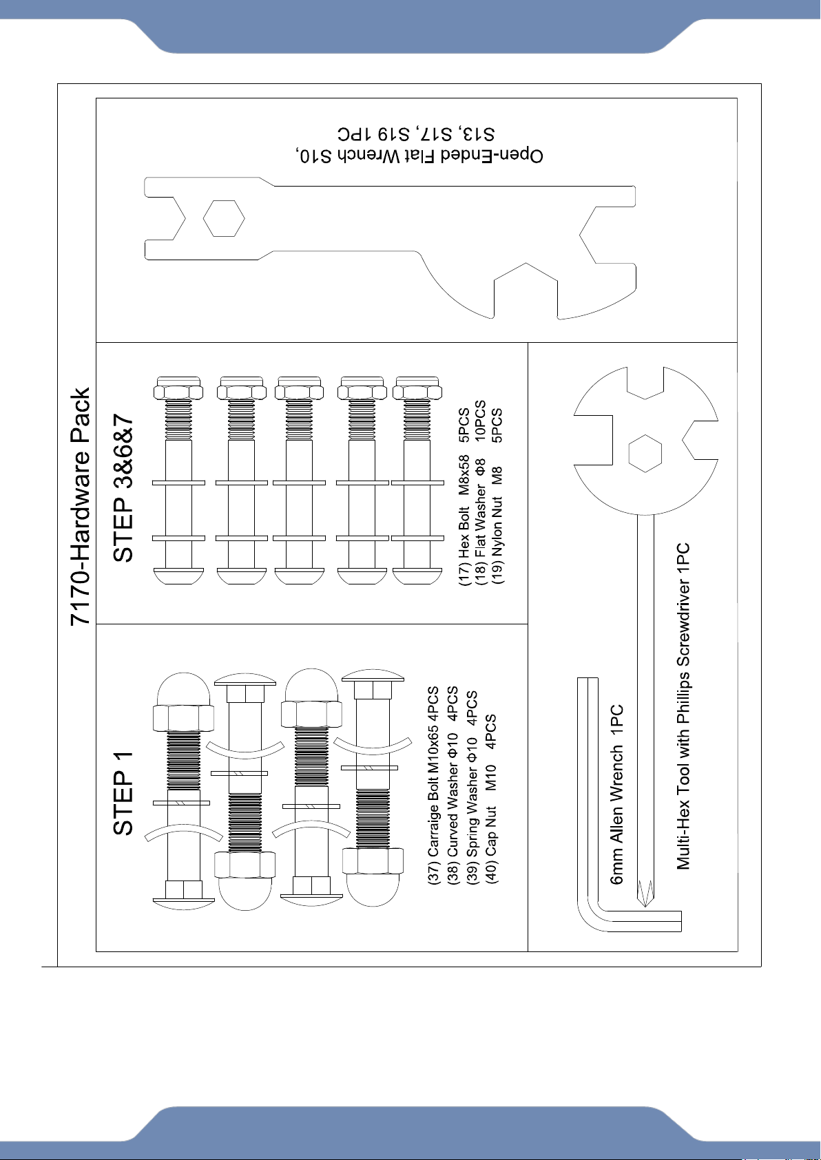
HARDWARE & TOOLS PACK
6
11
ASSEMBLY
Step 1
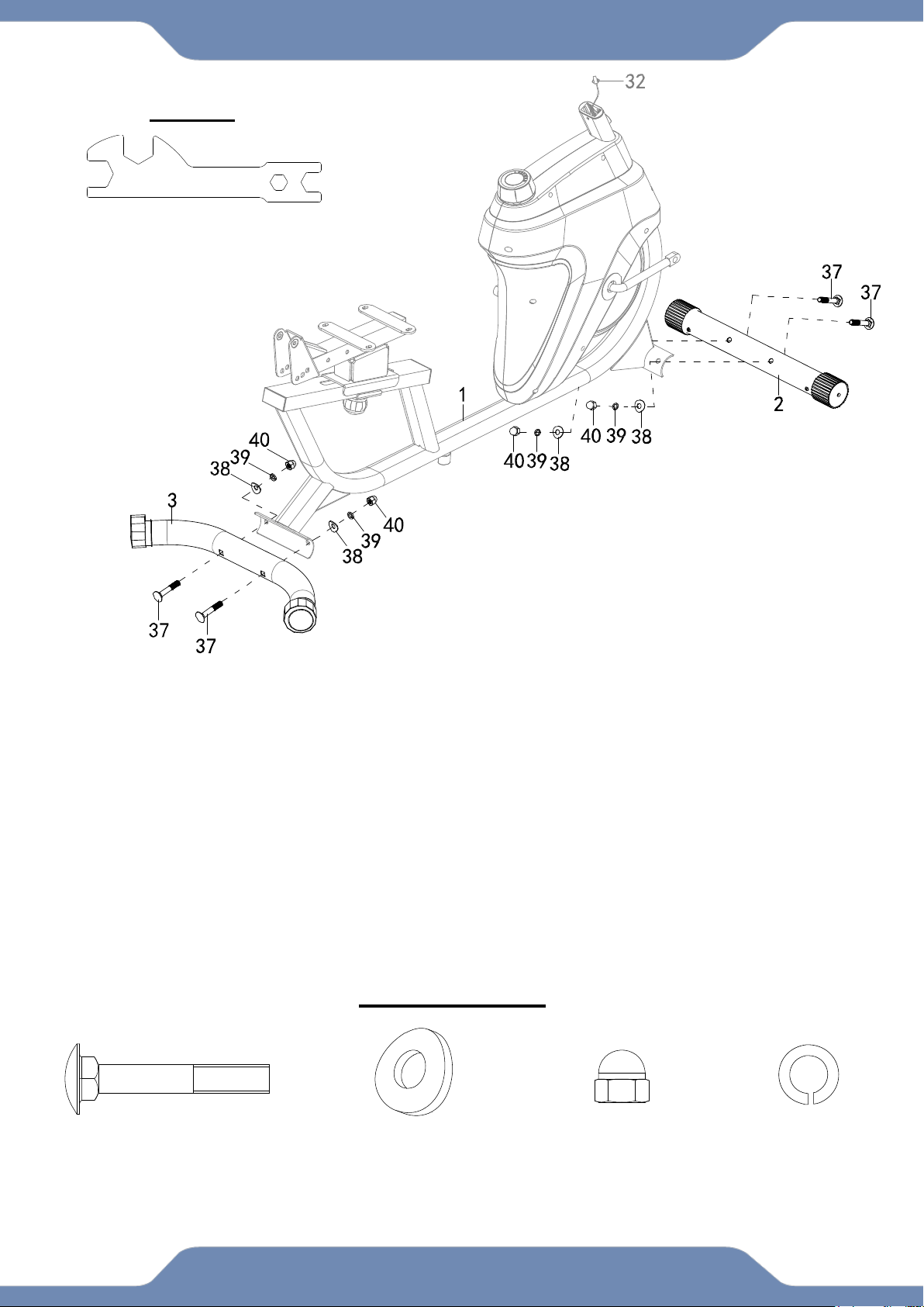
1A. Front Stabilizer Installation: Lift up the front of the Main Frame (1), and attach the Front
Stabilizer (2) onto the front curve of the Main Frame (1) with two Carriage Bolts (37), two Curve
Washers (38), two Spring Washers (39), and two Cap Nuts (40). Use the Open-Ended Flat
Wrench to tighten the Cap Nuts (40) until firm and secure.
1B. Rear Stabilizer Installation: Lift up the rear of the Main Frame (1), and attach the Rear
Stabilizer (3) onto the front curve of the Main Frame (1) with two Carriage Bolts (37), two Curve
Washers (38), two Spring Washers (39), and two Cap Nuts (40). Use the Open-Ended Flat
Wrench to tighten the Cap Nuts (40) until firm and secure.
Hardware Pack:
Open-Ended Flat Wrench
S10, S13, S17, S19 1PC
TOOLS
(37) Carriage Bolt
4 PCS
(38) Curved Washer
4PCS
(40) Cap Nut
4 PCS
(39) Spring Washer
4 PCS
12
ASSEMBLY
Step 2
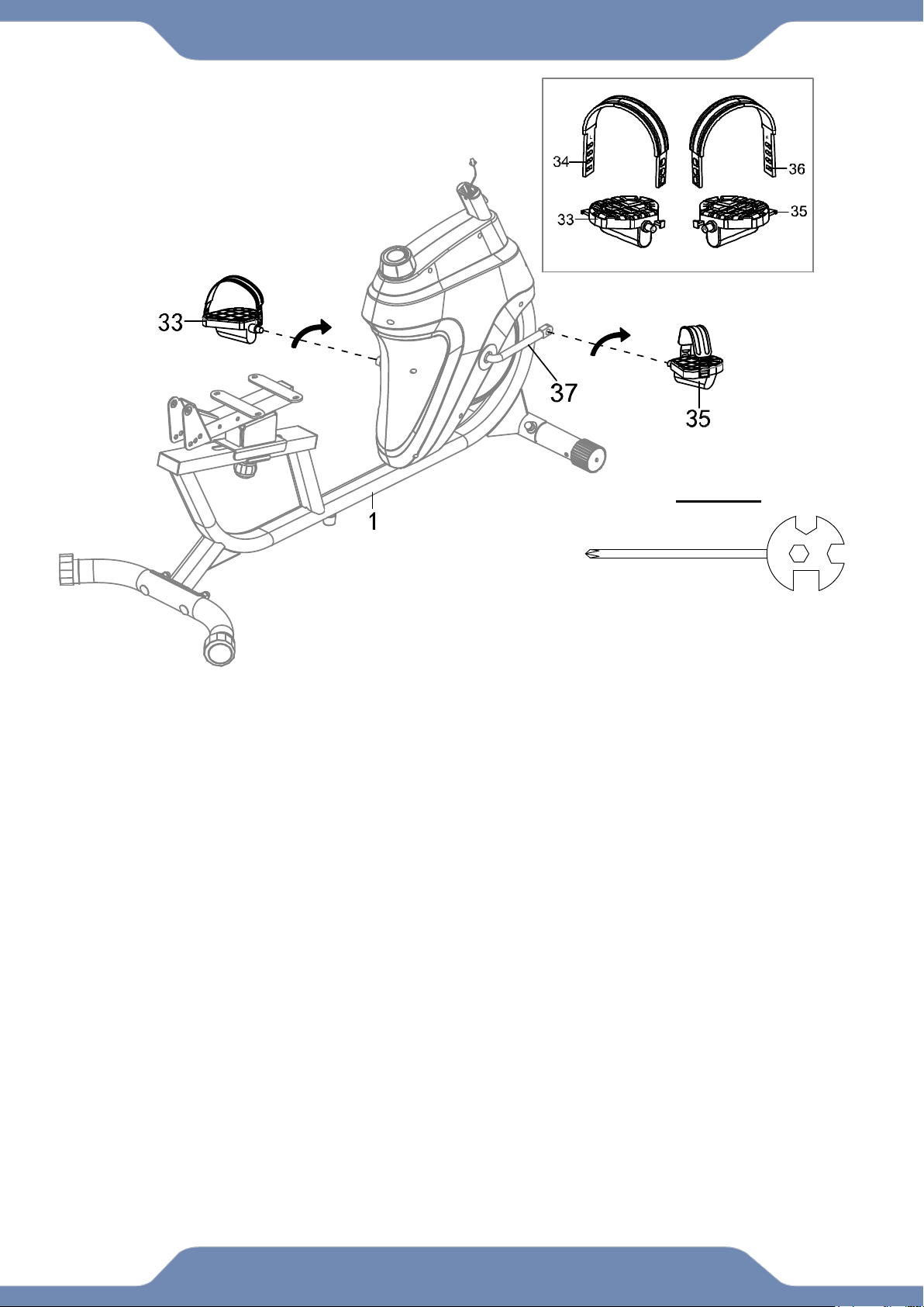
2A. Pedal Strap installation: Install the Left Pedal Strap (34) onto the Left Pedal
(33). Install the Right Pedal Strap (36) onto the Right Pedal (35).
2B. Left Foot Pedal Installation: Insert the threaded shaft of the Left Pedal (33) into the
threaded hole on the left side of the Crank (37). Turn the pedal shaft by hand in the
counter-clockwise direction until snug. Tighten the pedal shaft of the Left Pedal (33) with
the Multi Hex Tool with Phillips Screwdriver provided.
Note: DO NOT turn the LEFT pedal shaft in a clockwise direction; doing so will strip
the threads.
2C. Right Foot Pedal Installation: Insert the threaded shaft of the Right Pedal (35) into
the threaded hole on the right side of the Crank (37). Turn the pedal shaft by hand in the
clockwise direction until snug. Tighten the pedal shaft of the Right Pedal (35) with the
Multi Hex Tool provided.
Note: DO NOT turn the RIGHT pedal shaft in a counter clockwise direction; doing so
will strip the threads.
Multi Hex Tool
With Phillips Screwdriver
1PC
TOOLS
The Cranks, Pedal
Straps, Pedal Shafts,
and Foot Pedals are
marked “R” for Right
and “L” for Left.
13
ASSEMBLY
Step 3
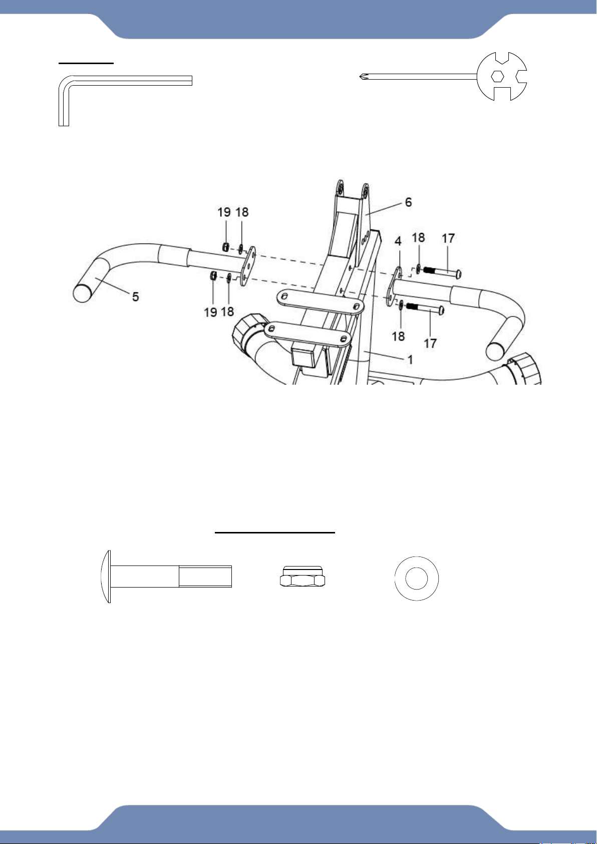
3A. Handlebar Installation: Attach the Left and Right Handlebars (4,5) onto the Seat Bracket
(6). Using two Hex Bolts (17), four Washers (18) and two Nylon Nuts (19). Then tighten with the
6mm Allen Wrench and the Multi Hex Tool with Phillips Screwdriver provided.
Multi Hex Tool
With Phillips Screwdriver
1PC
6mm Allen Wrench
1PC
TOOLS
Hardware Pack:
(17) Hex Bolt
2 PCS
(19) Nylon Nut
2 PCS
(18) Flat Washer
4 PCS
14
ASSEMBLY
STEP 4
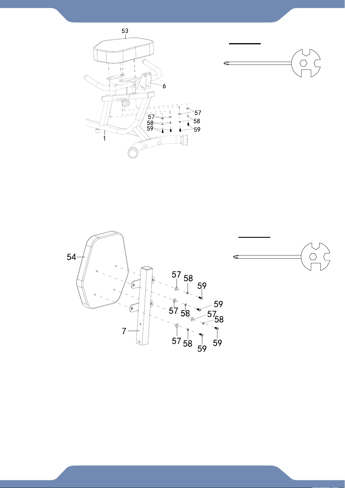
4A. Seat Installation : Remove the four Screws (59), four Spring Washers (58) and the four Flat
Washers (57) from the Seat (53). Align the holes of the Seat (53) to the holes of the Seat Bracket
(6). Secure the Seat (53) with four Screws (59), four Spring Washers (58) and the four Flat
Washers (57), Then tighten by using the Multi Hex Tool with Phillips Screwdriver provided.
STEP 5
5A. Backrest Installation : Remove the four Screws (59), four Spring Washers (58) and the four
Flat Washers (57) from the Backrest (54). Align the holes of the Backrest (54) to the holes of the
Backreat Frame (7). Secure the Backrest (54) with four Screws (59), four Spring Washers (58)
and the four Flat Washers (57), Then tighten by using the Multi Hex Tool with Phillips
Screwdriver provided.
Multi Hex Tool
S10, S13, S14, S15 1PC
TOOLS
Multi Hex Tool
S10, S13, S14, S15 1PC
TOOLS
15
ASSEMBLY
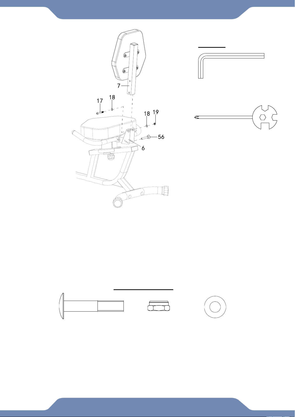
STEP 6
6A. Backrest Frame Installation: Insert the Backrest Frame (7) onto the Seat Bracket (6), and
align the hole tighten with one Hex Bolt (17), two Flat Washers (18) and one Nylon Nut (19).
Tighten the hardware with 6mm Allen Wrench and the Multi Hex Tool with Phillips
Screwdriver provided.
6B. Insert the Pin (56) onto the Seat Bracket (6).
(17) Hex Bolt
1 PC
(19) Nylon Nut
1 PC
(18) Flat Washer
2 PCS
Multi Hex Tool
S10, S13, S14, S15 1PC
6mm Allen Wrench
1PC
TOOLS
Hardware Pack:
16
ASSEMBLY
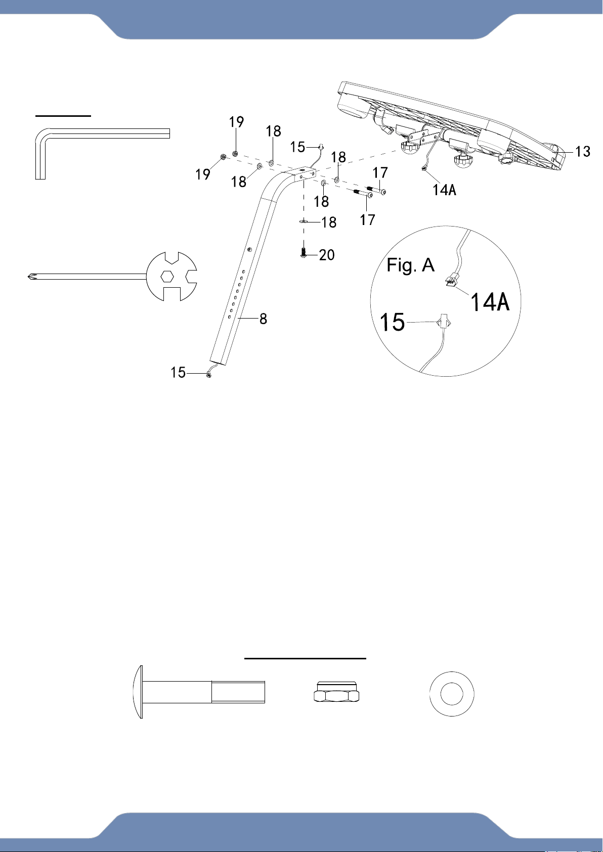
STEP 7
7A. Desk Installation: Remove one Flat Washer (18) and one Hex Bolt (20) from the Front Post
(8). Insert the Front Post (8) onto the bracket of the Desk (13), align the hole and tighten with two
Hex Bolts (17), four Flat Washers (18), two Nylon Nuts (19), one Flat Washer (18) and one Hex
Bolt (20) that were previously removed. Tighten the hardware with 6mm Allen Wrench and the
Multi Hex Tool with Phillips Screwdriver provided.
7B. Connecting the Console Wires: Connecting the Console Wire 14A (FIG.A) from the Desk
(13) with the Console Wire (15) from the Front Post (8). See Fig. A.
Multi Hex Tool
S10, S13, S14, S15 1PC
6mm Allen Wrench
1PC
TOOLS
(17) Hex Bolt
2 PCS
(19) Nylon Nut
2 PCS
(18) Flat Washer
4 PCS
Hardware Pack:
17
ASSEMBLY
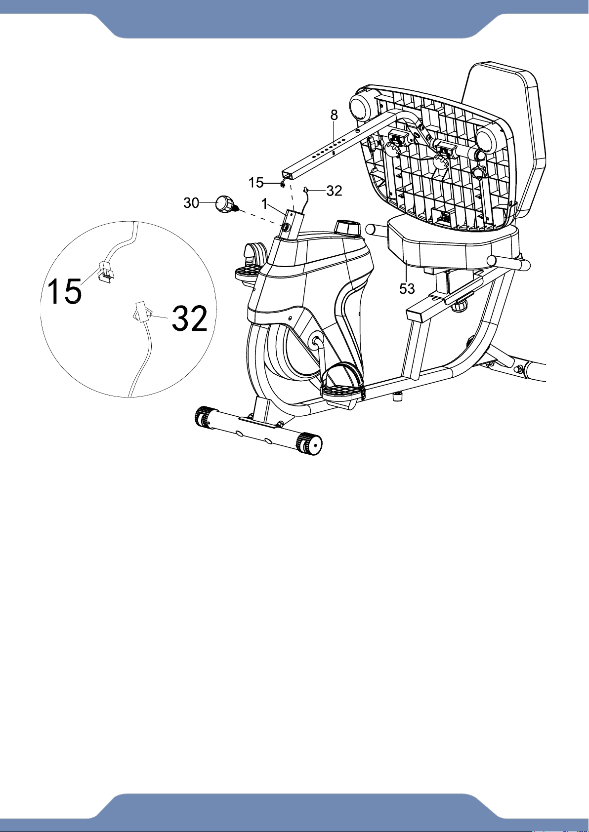
STEP 8
8A. Rest the Desk (13) on the Seat (53) as shown.
8B. Connecting Wires: Connect the Console Wire (15) from the Front Post (8) to the Sensor
Wire (32) sticking out from the Main Frame (1).
8C. Front Post Installation: Guide the connected wires (15) and (32) into the Main Frame (1)
tube as you insert the Front Post (8) into the Main Frame (1). Adjust the height as needed and
Insert the Spring Knob (30) to catch one of the holes along the Front Post (8). Turn the Spring
Knob (30) clockwise to tighten and lock the desk height.
Fig. B
18
CONSOLE
SPECIFICATIONS:
TIME -----------------------------0:00-99:59 MIN:SEC
SPEED --------------------------0.0-99.9 ML/H
DISTANCE ---------------------0.0-999.9 ML
CALORIE -----------------------0.0-9999 KCAL
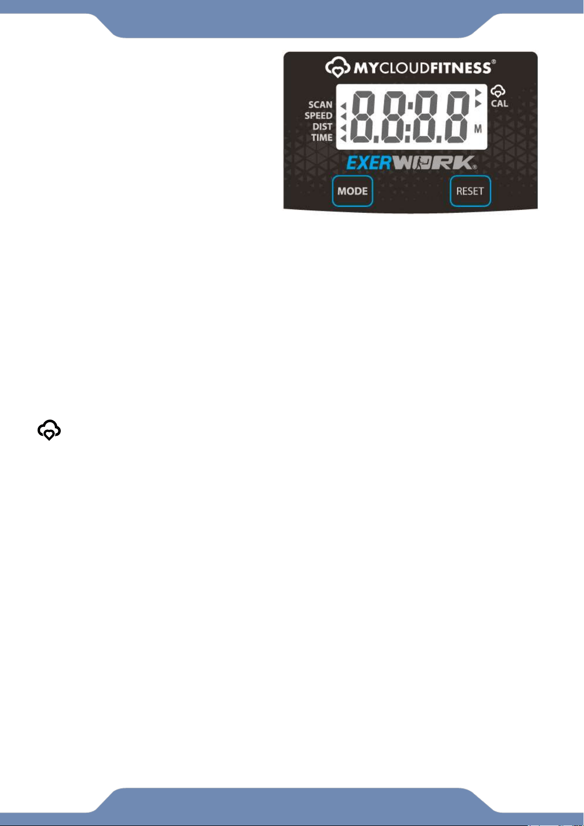
CONSOLE FUNTIONS:
MODE: Press the “MODE” button to select between, SCAN,SPEED,DISTANCE,TIME, and CALORIES.
AUTO ON/OFF: The console will automatically turn on when pedaling begins. The console will
automatically turn off after 20 minutes of inactivity.
SCAN: Press the “MODE” button until the arrow (◄) points to “SCAN”. The console will automatically scan
the workout statistics of TIME, SPEED, and DISTANCE, every 6 seconds.
TIME: Press the “MODE” button until the arrow (◄) points to “TIME”. The console will display the total time
exercised in minutes and seconds. The console automatically counts up from 0:00 to 99:59 in one second
intervals.
SPEED: Press the “MODE” button until the arrow (◄) points to “SPEED”. The console will display your
current workout speed in miles per hour.
DISTANCE: Press the “MODE” button until the arrow (◄) points to “DIST”. The console will display the
distance traveled during each workout up to a maximum of 999.9 miles.
CALORIE: Press the “MODE” button until the arrow (►) points to “CAL”. The console will estimate the
cumulative calories burned during a workout. The console will count up from 0.0 to 9999 calories.
When the MyCloudFitness logo is blinking, it is scanning for bluetooth devices. Once its
paired to a device the MyCloudFitness logo will stop blinking.
RESET: Hold this button for 4 seconds to reset all values from the console, Except ODOMETER.
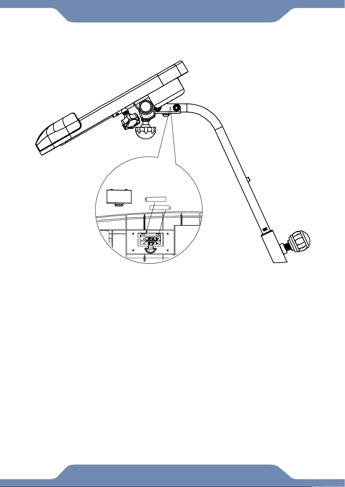
HOW TO INSTALL THE BATTERIES:
1. Remove the battery cover on the underside of the Desk (88).
2. Place two "SIZE-AAA" batteries into the battery housing.
3. Insure the batteries are correctly positioned and the battery springs are in proper contact
with the batteries.
4. Re-install the battery cover.
5. If the display is illegible or only partially legible, remove the batteries and wait 15 seconds
before reinstalling.
19
ADJUSTMENT
ADJUSTING THE REAR STABILIZER END CAP:
Adjust the Rear Stabilizer End Caps (43) on the Rear Stabilizer (3) as needed to
level the recumbent bike.
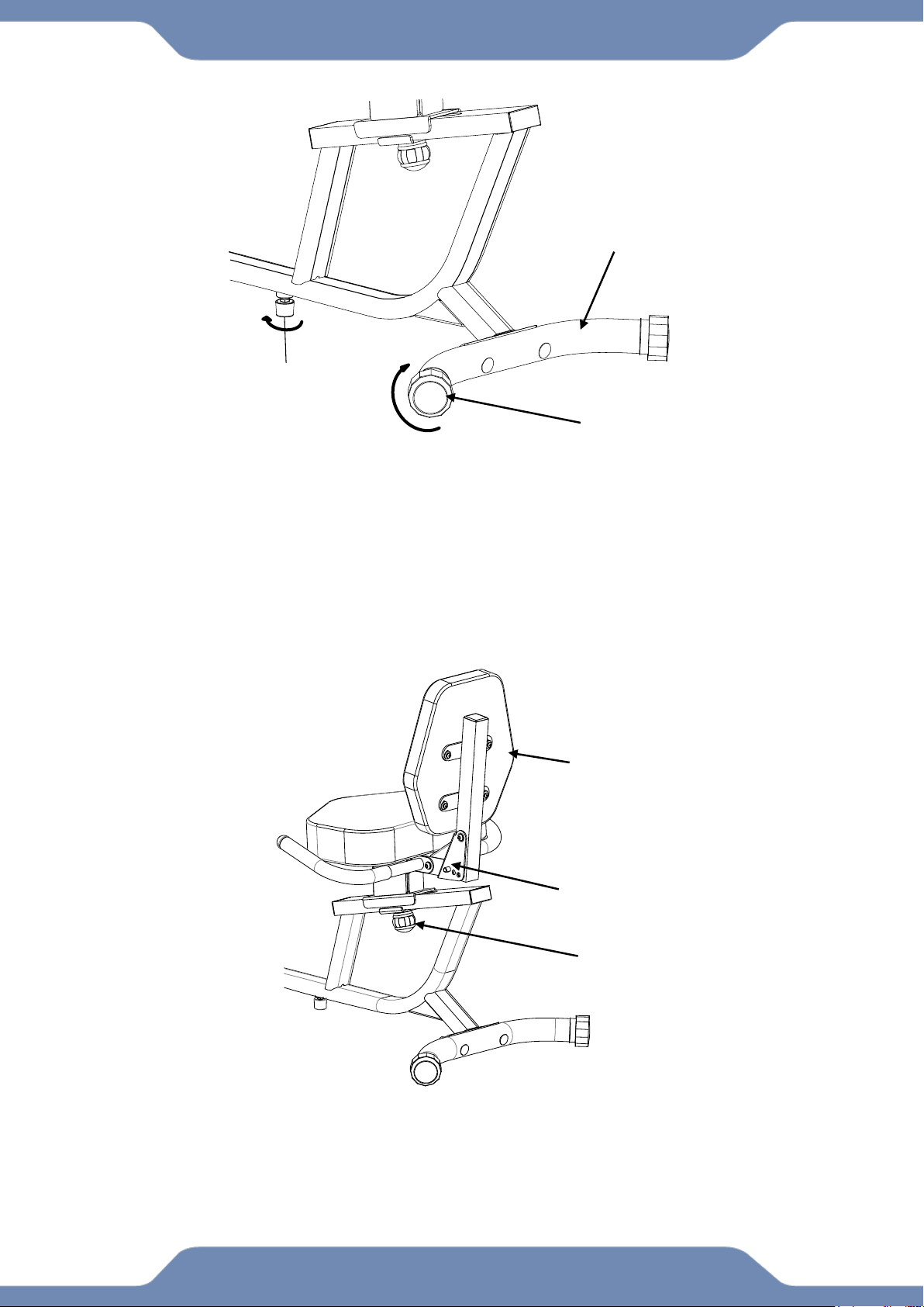
ADJUST THE ADJUSTABLE LEVELER:
If the bike is bouncing when in use, turn the Adjustable Leveler (45) so that is
making contact with the floor. Do not extend the Adjustable Leveler (45) too far,
as this will cause the bike to tilt and be off balance.
ADJUSTING THE SEAT FORWARD OR BACK:
Loosen the Round Knob (50) in a counter-clockwise direction until the seat is
loosen, Standing behind the seat, use two hands to push or pull the Backrest (54).
Once you find the position you like, lock the Seat Bracket (6) into place by turning
the Round Knob (50) in a clockwise direction until it is secured tightly.
Round Knob (50)
16
Seat Bracket (6)
Rear Stabilizer End Cap (43)
Rear Stabilizer (3)
Adjustable Leveler (45)
Backrest (54)
20
ADJUSTMENT
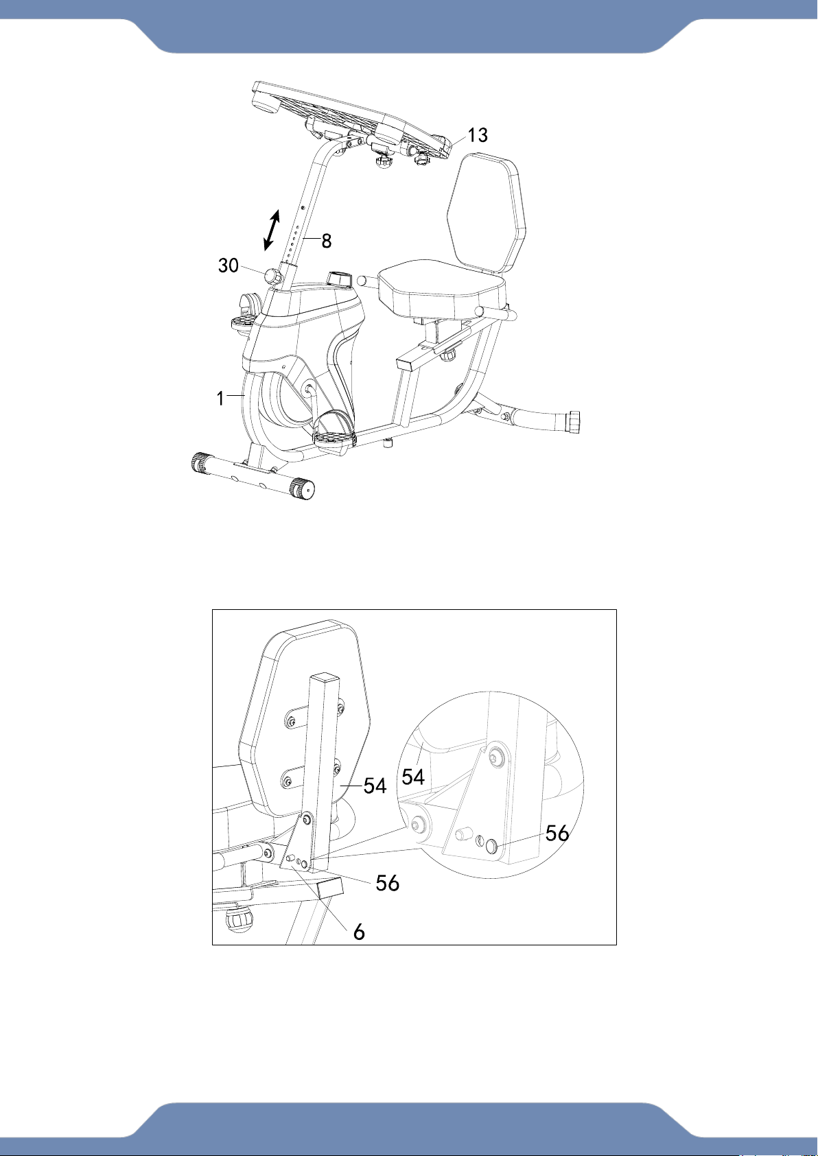
ADJUSTING THE DESK HEIGHT:
Loosen the Spring Knob (30) and lift up or down the Desk (13) to desired position.
ADJUSTING THE BACKREST:
Insert the Pin (56) into hole on the Seat Bracket (6) to adjust the Backrest (54) to
desired postition.
21
ADJUSTMENT
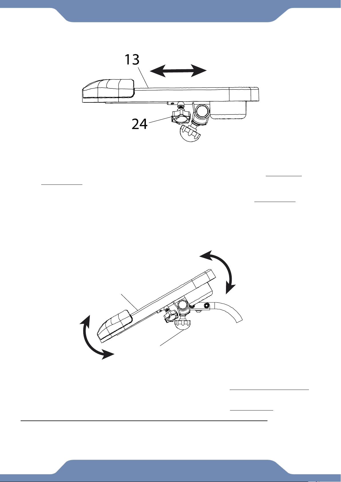
ADJUSTING THE DESK RANGE:
1. Loosen the Left and Right Adjustable Post Knobs (24) by turning them COUNTER-
CLOCKWISE.
2. Shift the Desk (13) forward or backwards to the desired position.
3. Tighten the Left and Right Adjustable Post Knobs (24) by turning it CLOCKWISE to
lock the Desk(13) in place.
NOTE* Please remove all items from the desktop before making any
adjustments.
DESK TILT ADJUSTMENT:
1. Loosen the Left and Right Round Knobs (29) by turning them COUNTER-CLOCKWISE.
2. Tilt the Desk (13) Up or Down to desired position.
3. Tighten the Left and Right Round Knobs (29) by turning them CLOCKWISE.
NOTE* DO NOT EXCEED the maximum weight limit of 44lbs. of the desktop.
Please remove all items from the desktop before making any adjustments.
29
13
22
OPERATIONS & ADJUSTMENTS
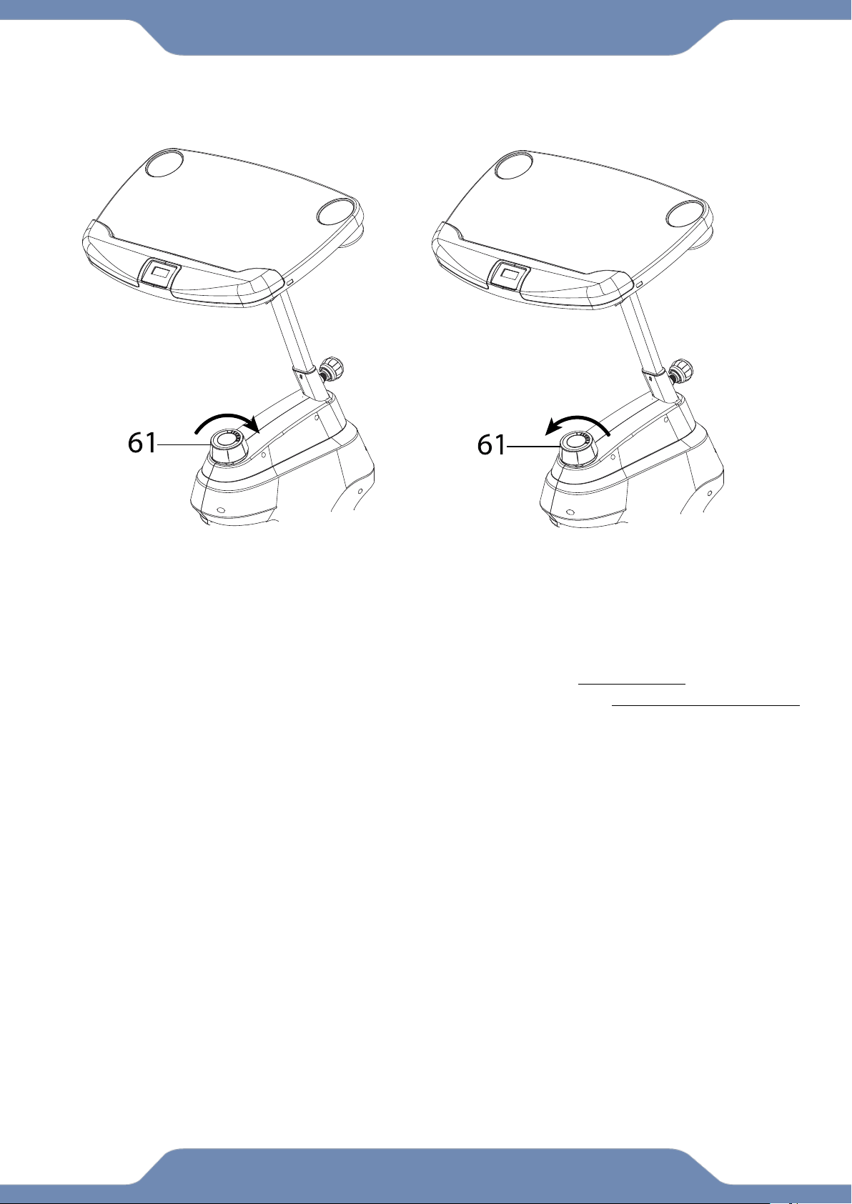
ADJUSTING THE TENSION CONTROL KNOB
To increase the resistance, turn the Tension Control Knob (61) in a CLOCKWISE direction.
To decrease the resistance, turn the Tension Control Knob (61) in a COUNTERCLOCKWISE
direction.
INCREASE
DECREASE
23
BATTERY INSTALLATION
HOW TO INSTALL THE BATTERIES:
1. Remove the battery cover on the back of the computer.
2. Place two "SIZE-AAA" batteries into the battery housing.
3. Ensure that the batteries are correctly positioned and that the battery springs are in proper
contact with batteries.
4. Re-install the battery cover.
24
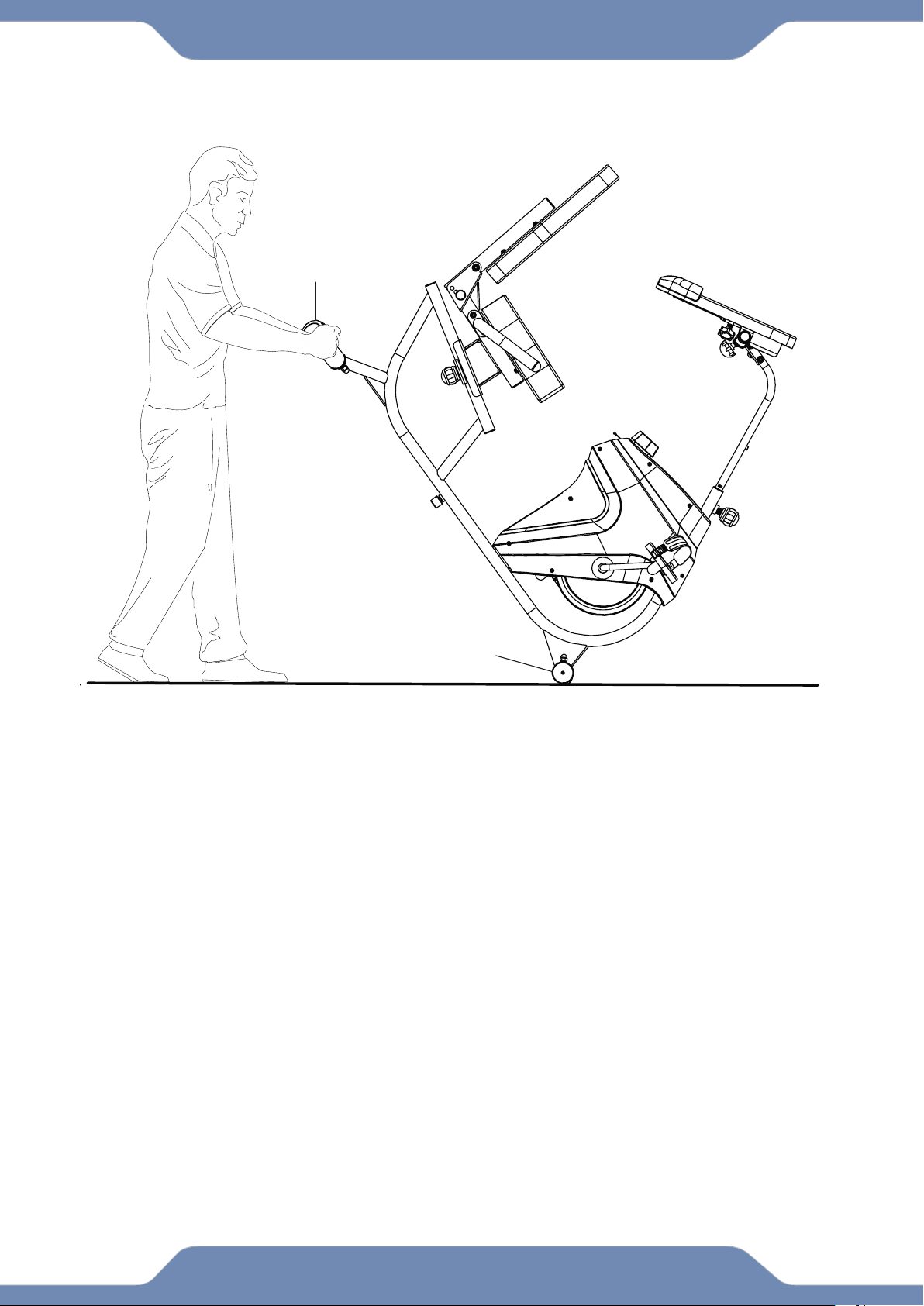
TRANSPORTATION
TRANSPORTING THE BIKE
1. Hold onto the Rear Stabilizer (3) and tilt the bike onto to the wheels of the Front
Stabilizer (2).
2. Carefully move the bike to the desired location.
3. Gently lower the bike until the Rear Stabilizer (3) touches the floor.
NOTE* Please remove all items from the desktop before making any
adjustments.
3
2

25
TROUBLE SHOOTING & MAINTENANCE
TROUBLE SHOOTING
PROBLEM: The recumbent bike wobbles when in use.
1)SOLUTION: Turn the Rear Stabilizer End Caps (43) on the Rear Stabilizer (3) or
Adjustable Leveler (45) on the bottom of the rear Main Frame (1) as needed to
level the recumbent bike.
PROBLEM: The display on the Console (14) does not turn on or displays incorrect
information.
1) SOLUTION: Remove the Console (14) and verify that the wires from the console
(10) are properly connected to the wires of the Front Post (8).
2) SOLUTION: Check if the batteries are installed properly or replace dead batteries.
PROBLEM: The recumbent bike makes a squeaking noise when in use.
1) SOLUTION: The bolts may be loose on the recumbent bike. Inspect all of the
bolts and tighten any loose bolts.
MAINTENANCE
Cleaning:
The recumbent bike can be cleaned with a soft clean damp cloth.
Do not use abrasives or solvents on the plastic parts.
Please wipe your perspiration off the recumbent bike after each use.
Be careful not to get excessive moisture on the Console display as this might cause
an electrical hazard or the electronics to fail.
Please keep the recumbent bike, especially the computer console out of direct
sunlight to prevent screen damage.
Please inspect that all assembly bolts, nuts, screws, and pedals on the machine are
thoroughly tightened every week. Tighten any loose parts.
Storage:
Store the recumbent bike in a clean and dry environment away from children.
