

Folding Upright Bike with Pulse
IMPORTANT:
Read all instructions carefully before using this product. Retain this owner’s manual for
future reference.
The specifications of this product may vary from this photo, subject to change without notice.
OWNER’S MANUAL
1200.17-071719


1
SERVICE --------------------------------------------------------------------------2
LABEL PLACEMENT ---------------------------------------------------------- 3
IMPORTANT SAFETY GUIDELINES -------------------------------------- 4
OVERVIEW DRAWING -------------------------------------------------------- 6
PARTS LIST ----------------------------------------------------------------------- 7
HARDWARE & TOOLS PACK ------------------------------------------------ 9
ASSEMBLY ------------------------------------------------------------------------ 10
CONSOLE -------------------------------------------------------------------------- 15
STORAGE -------------------------------------------------------------------------- 16
OPERATIONS & ADJUSTMENTS ------------------------------------------- 17
TRANSPORTATION ------------------------------------------------------------- 20
MAINTENANCE & TROUBLESHOOTING -------------------------------- 21
WARRANTY ----------------------------------------------------------------------- 22
PARTS REQUEST FORM ----------------------------------------------------- 23
TABLE OF CONTENT

2
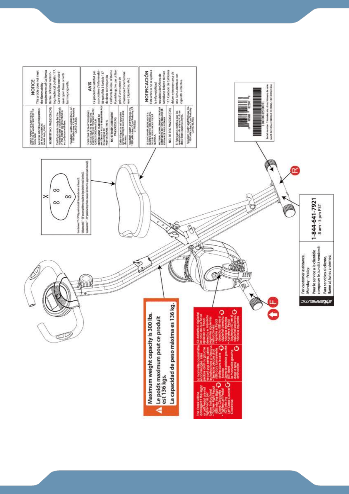
IMPORTANT: FOR NORTH AMERICA ONLY
For damaged or defective product, questions, replacement parts or any other service
support, please contact our customer service department (8:00 AM - 5:00 PM Pacific
Standard Time, Monday thru Friday) by the below methods:
For The Best Service, please Email:
service@paradigmhw.com
Response Time: 1-2 Business Days
Emailing us with the information above will be the best method to receive a response during
peak business hours
Website:
www.paradigmhw.com
Toll-Free:
1-844-641-7921
Monday thru Friday (PST)
Response time may vary via calling
Refer to our email for the best response time
Please have the following information ready when requesting for service:
Your name
Phone number
Model number
Serial number
Part number
Proof of Purchase
For damaged or defective product please contact our customer service before returning to
the store.
Paradigm Health & Wellness, Inc.
1189 Jellick Ave.
City of Industry, CA 91748, USA
SERVICE
3
LABEL PLACEMENT

4
Read all instructions before using the Bike. When using our equipments, basic precautions should
always be followed, including the following:
WARNING - To reduce the risk of injury to persons:
1. Make sure your equipment is correctly assembled before you use it.
2. Be sure all screws, nuts, and bolts are tightened prior to use.
3. Only one person should use the equipment at a time.
4. Never operate this equipment if it is damaged, If it is not working properly, has been dropped, or
damaged. If a problem is encountered contact Customer Service before using the equipment again.
5. Always use this equipment on a clear and level surface.
6. For household use only.
7. Do not use outdoors or near water.
8. Use the equipment only for its intended use as described in this manual. Do not use attachments not
recommended by the manufacturer.
9. Do not wear loose clothing when using the equipment.
10. Keep all hands and feet away from any moving parts.
11. Never drop or insert any object into any opening.
12. Always wear shoes when using the equipment.
13. This equipment is not intended for use by persons with reduced physical, sensory or mental capabilities,
or lack of experience and knowledge, unless they have been given supervision or instruction concerning use
of the equipment by a personal responsible for their safety.
14. If at any time you feel faint, light-headed, or dizziness while operating the equipment, stop exercising
immediately. You should also stop exercising if you are experiencing pain or any discomfort.
15. DO NOT pedal in reverse.
16. Assemble All Parts & Hardware Accordingly To The Assembly Steps. Use The
Illustrations For Reference.
17. Warning: - Risk of Personal Injury – Do not allow children to use this machine.
18. Warning: - Risk of Personal Injury – Keep body parts, hair, loose clothing, and jewelry clear of all
moving parts.
19. Warning: - Risk of Personal Injury - Do not attempt to service the unit yourself. Discontinue use and
contact customer service.
20. WARNING: CANCER AND REPRODUCTIVE
HARM--WWW.P65WARNINGS.CA.GOV.
The maximum weight capacity for this product is 300 lbs/136 kgs.
WARNING: Before beginning any exercise program consult your physician.
This is especially important for the people who are over 35 years of age or who have
pre-existing health problems. Read all instructions before using any fitness equipment.
CAUTION: Read all instructions carefully before operating this product.
Retain this Owner’s Manual for future reference.
IMPORTANT SAFETY GUIDELINES
!
!

5
The product weighs more than 44 lbs. It is heavily
recommended that at least 2 persons assemble.
Do not use this equipment if you have any of the following conditions or ailments:
Pregnancy
Extreme obesity
Middle ear infection
Hiatus hernia or Ventral hernia
Glaucoma, retinal detachment or conjunctivitis
Use of anticoagulants including Aspirin in high doses.
Spinal injury, Cerebral Sclerosis, or acutely swollen joints
Heart or circulatory disorders for which you are being treated
High blood pressure, Hypertension, Recent stroke or Transient Ischemic attack
Bone weaknesses including Osteoporosis, Unhealed fractures, Modular pins, or surgically implanted
orthopedic supports.
Do not exceed the maximum rated weight (load) and maximum rated
user height:
The Maximum Weight Capacity for this product is 300lbs/136kgs.
Retain this owner’s manual and keep the original purchase receipt
for future reference.
SAVE THESE GUIDELINES
IMPORTANT SAFETY GUIDELINES
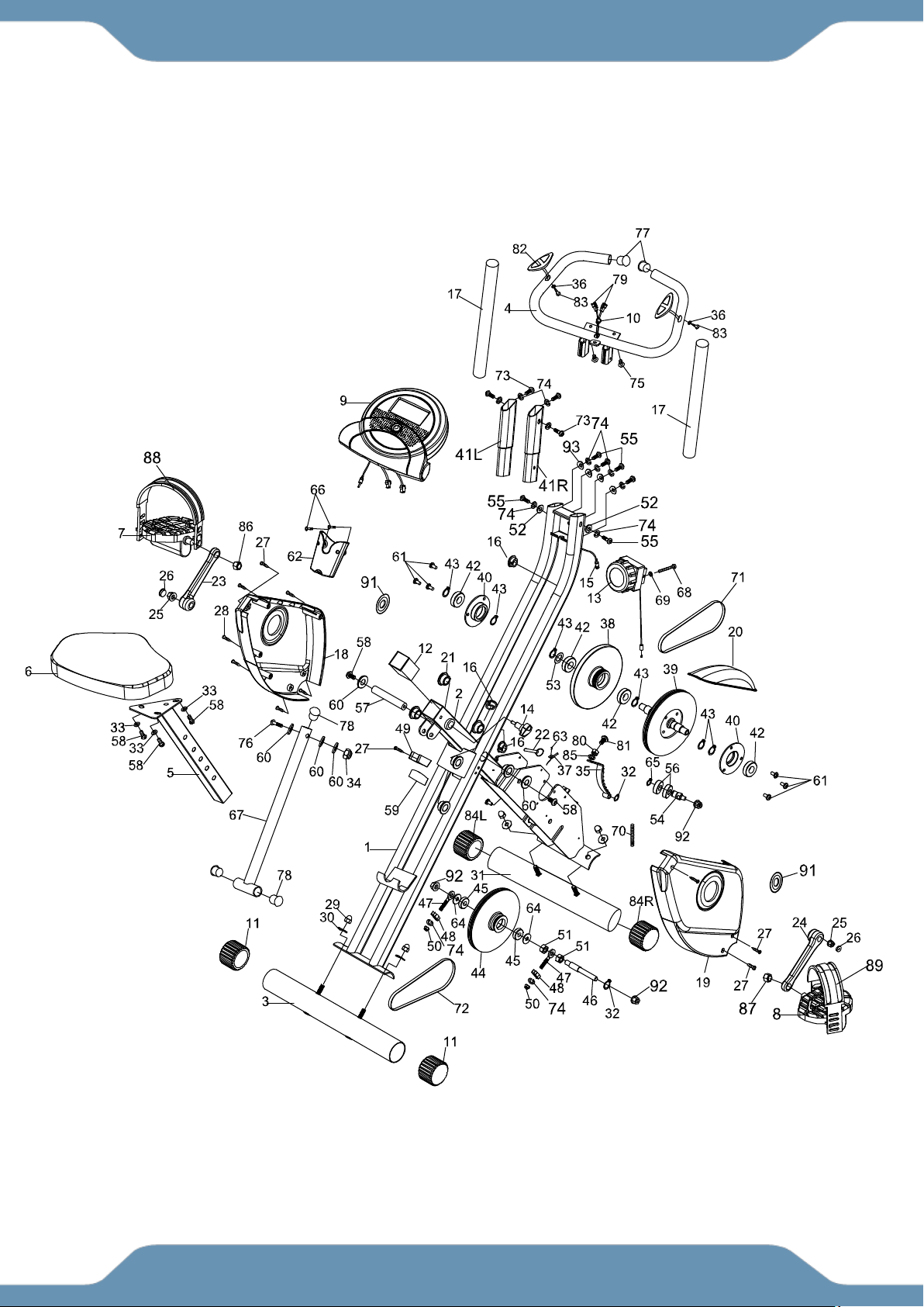
6
OVERVIEW DRAWING

7
No.
Description
Qty
No.
Description
Qty
1
Rear Frame
1
30
Curved Washer Ø8.2xØ22.2
4
2
Front Frame
1
31
Front Stabilizer
1
3
Rear Stabilizer
1
32
C-ring Ø10
2
4
Handlebar Ø25
1
33
Flat Washer Ø8.2xØ16.8
3
5
Seat Post
1
34
Nylon Nut M8
1
6
Seat Cushion
1
35
Magnet Bracket
1
7
Left Pedal
1
36
Washer Ø6.2
2
8
Right Pedal
1
37
Sensor Clip
1
9
Console
1
38
Flywheel
1
10
Wire Plug
1
39
Belt Wheel with Crank Axle
1
11
Rear Stabilizer End Cap
2
40
Bearing Bracket A
2
12
Seat Post Plastic Bushing
1
41R
Right Handlebar Extension
1
13
Tension Control Knob
1
41L
Left Handlebar Extension
1
14
Seat Height Adjustment Knob
1
42
Bearing 6003RS
4
15
Sensor Wire
1
43
C-ring Ø17
6
16
Oval Wire Plug
3
44
Belt Wheel
1
17
Handlebar Foam Grip
2
45
Bearing 6000Z
2
18
Left Cover
1
46
Axle Ø12.8x94L
1
19
Right Cover
1
47
Eyebolt M6
2
20
Top Cover
1
48
Tension Bracket
2
21
Round Plastic Bushing
6
49
Support Tube Clip
1
22
Safety Pin
1
50
Nylon Nut M6
2
23
Left Crank
1
51
Nut M10
2
24
Right Crank
1
52
Flat Washer Ø6.2
2
25
Flange Nut
2
53
Wave Washer Ø17
1
26
Crank Cover
2
54
Idle Wheel Axle
1
27
Round Head Drilling Phillips
Screw M4x20
7
55
Hex Bolt M6x15
6
28
Round Head Tapping Phillips
Screw M4x20
4
56
Bearing 6902Z
2
29
Hexagon Nut Cap M8
4
57
Axle
1
PARTS LIST

8
No.
Description
Qty
No.
Description
Qty
58
Hex Bolt M8x15
5
76
Hex Bolt M8x43L
1
59
Rubber Cushion
1
77
Handlebar End Cap Ø25.4
2
60
Washer Ø8.2x Ø25x2.0t
5
78
Front Frame Support Tube End
Cap
3
61
Flat Head Phillips Screw M6x11
6
79
Hand Pulse Sensor Wire
2
62
Bottle Holder
1
80
Nut M6
1
63
Round Head Phillips Screw
M4x10
1
81
Screw M6x15
1
64
Plastic Washer
2
82
Hand Pulse Sensor
2
65
C-ring Ø15
1
83
Countersunk Head Phillips Screw
M4x20
2
66
Screw M4x10L
2
84R
Rihgt Front Stabilizer End Cap
1
67
Support Tube
1
84L
Left Front Stabilizer End Cap
1
68
Screw M5x20
1
85
Spring Washer Ø6.2
1
69
Washer Ø5.2xØ18
1
86
Left Pedal Nut 9/16
1
70
Spring
1
87
Right Pedal Nut 9/16
1
71
Belt 240J4
1
88
Left Pedal Strap
1
72
Belt 230J3
1
89
Right Pedal Strap
1
73
Hex Bolt M6x12
4
91
Crank Cap
2
74
Spring Washer Ø6.2
12
92
Flange Nut M10
3
75
Screw M5x15
2
93
Curved Washer Ø6.2
4
PARTS LIST
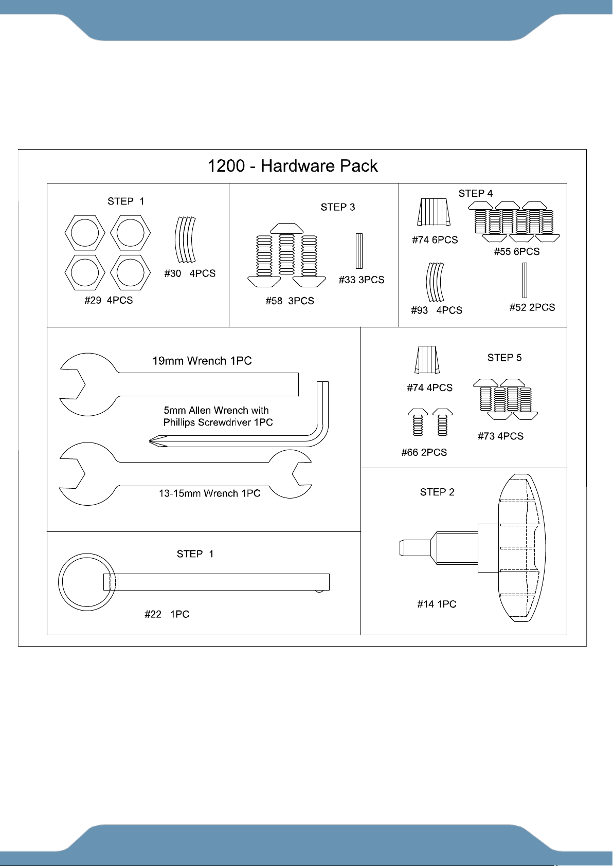
9
HARDWARE & TOOLS PACK
10
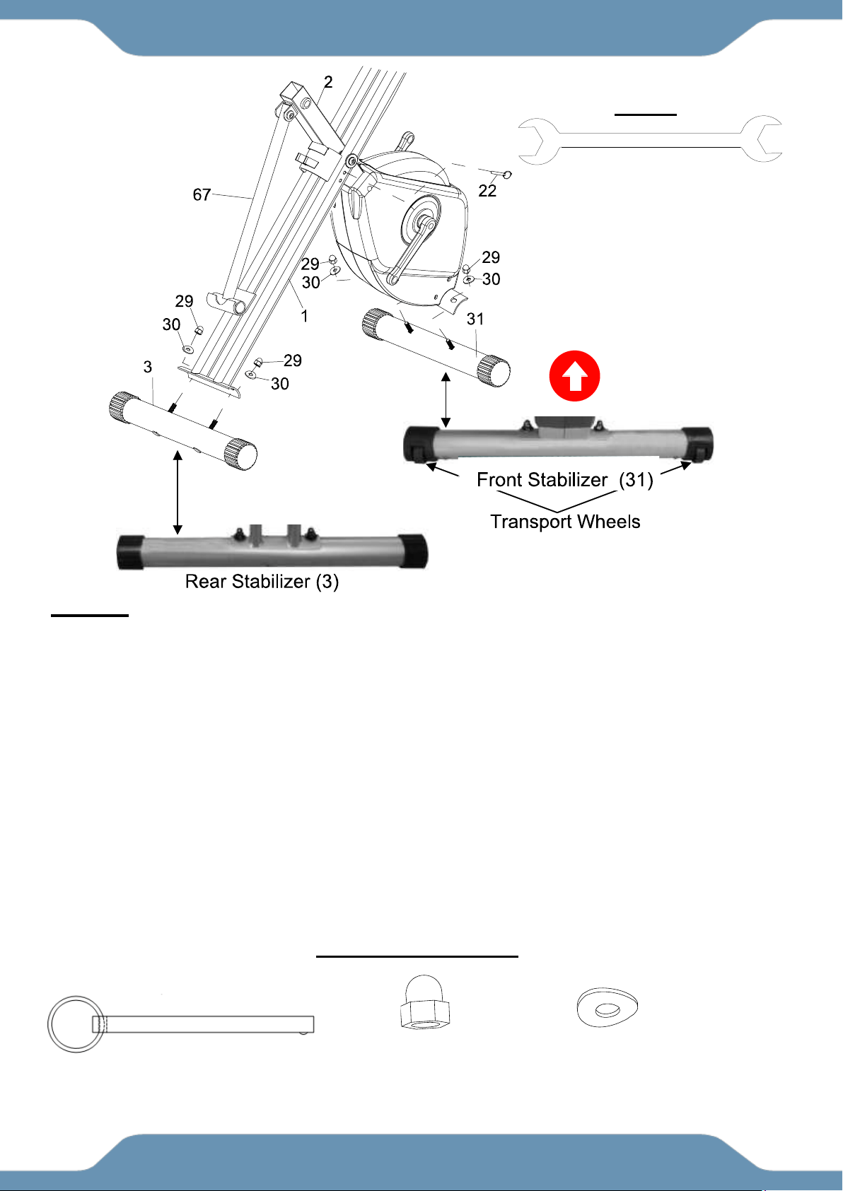
STEP 1
1A Setting Up The Frames Of The Bike: Stand up the base of the Rear and Front Frames (1, 2)
by pulling them apart from each other. Rest the Support Tube (67) into the hooked plate on the
Rear Frame (1). Align the upper pin holes on where both Frames (1, 2) intersect and insert the
Safety Pin (22) to lock the frames in place.
1B Installing The Front Stabilizer: Ensuring that the UP Sticker is visible on the outside and
facing correctly, attach the Front Stabilizer (31) with the Transport Wheels onto the Front Frame
(2) with two Hexagon Nut Caps (29) and two Curved Washers (30). Tighten the Hexagon Nut
Caps (29) with the 13 - 15mm Wrench provided.
1C Installing The Rear Stabilizer: Ensuring that the UP Sticker is visible on the outside and
facing correctly, attach the Rear Stabilizer (3) onto the Rear Frame (1) with two Hexagon Nuts
Cap (29) and two Curved Washers (30). Tighten the Hexagon Nut Caps (29) with the 13 – 15mm
Wrench provided.
ASSEMBLY
TOOL
13-15mm Wrench
HARDWARE PACK
(22) Safety Pin
1 PC
(29) Hexagon Nut Cap M8
4PCS
(30) Curve Washer
4 PCS
HARDWARE PACK
(29) Hexagon Nut Cap
4PCS
(30) Curved Washer
4PCS
(22) Safety Pin
1PC
HARDWARE PACK
11
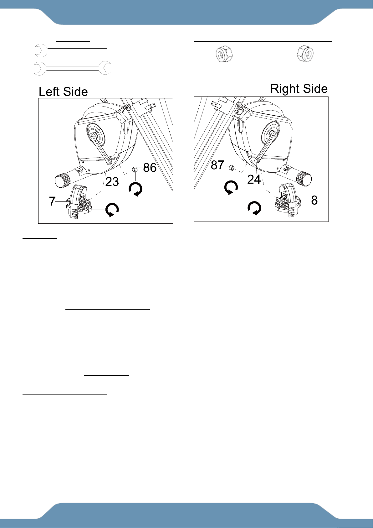
STEP 2
Tip: Only turn the pedals in the direction instructed. The left and right pedals have different
turning directions for installation. The Cranks, Pedals, Pedal Shafts, Pedal Nuts, and Pedal
Straps are marked “R” for Right and “L” for Left.
2A Installing The Left Pedal Onto The Left Crank: Remove the Left Pedal Nut (86). Insert the
Left Pedal (7) perfectly straight into the threaded hole in the Left Crank (23). Turn the pedal shaft
by hand in a COUNTER-CLOCKWISE direction until snug. Use the the 13 – 15mm Wrench to fully
tighten the Left Pedal (7). Attach the Left Pedal Nut (86) to the protruding shaft in a CLOCKWISE
direction. Use both the 13-15mm Wrench and 19mm Wrench to simultaneously tighten the Left
Pedal (7) and the Left Pedal Nut (86). Only tighten in the directions instructed.
2B Installing The Right Pedal Onto The Right Crank: Remove the Left Pedal Nut (86) Insert the
Right Pedal (8) perfectly straight into the threaded hole in the Right Crank (24). Turn the pedal
shaft by hand in a CLOCKWISE direction until snug. Use the the 13 – 15mm Wrench to fully
tighten the Right Pedal (8). Attach the Right Pedal Nut (87) to the protruding shaft in a
COUNTER-CLOCKWISE direction. Use both the 13-15mm Wrench and 19mm Wrench to
simultaneously tighten the Right Pedal (8) and the Right Pedal Nut (87). Only tighten in the
directions instructed.
2C Installing The Pedal Straps To The Pedals: Install the Left Pedal Strap (88) onto the Left
Pedal (7). Install the Right Pedal Strap (89) onto the Right Pedal (8). See Operations &
Adjustment Page.
ASSEMBLY
TOOLS
13-15mm Wrench
19mm Wrench
PREINSTALLED HARDWARE
(86) Left Pedal Nut
1 PC
(87) Right Pedal Nut
1 PC
12
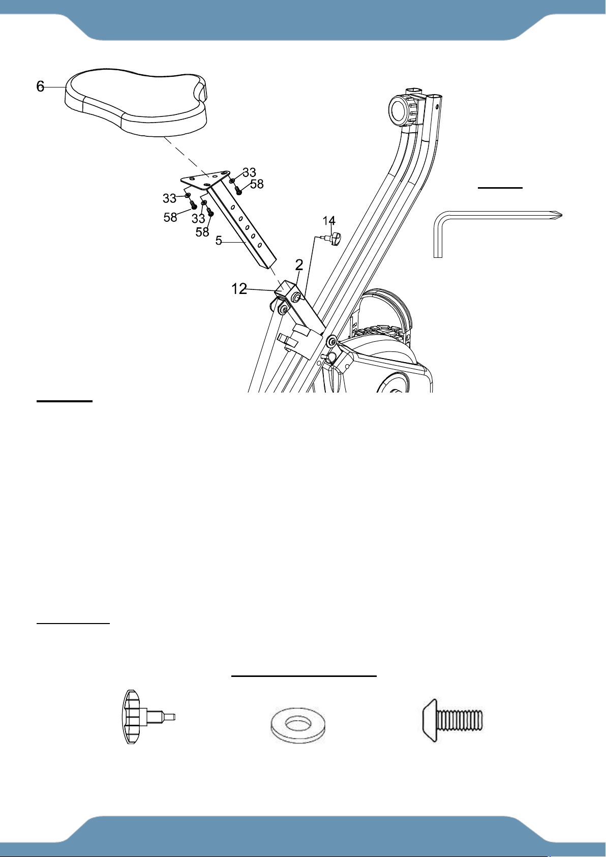
STEP 3
Tip: The Seat Cushion (6) has 2 sets of adjustment holes. It is recommended that users between
5’1” – 5’6” use the holes towards the rear of the seat and users between 5’7” to 6’3” use the holes
towards the front. See Operations & Adjustment Page 18.
3A Installing The Seat Cusion To The Seat Post: Align the bolt holes on the underside of the
Seat Cushion (6) with the holes on top of the Seat Post (5). Attach the Seat Cushion (6) to the
Seat Post (5) with three Flat Washers (33) and three Hex Bolts (58). Tighten the Hex Bolts (58)
with the 5mm Allen Wrench with Phillips Screwdriver provided.
3B Installing The Seat Post To The Front Frame: After securing the Seat Cushion (6) to the
Seat Post (5), insert the Seat Post (5) through the Seat Post Plastic Bushing (12) and into the
tube of the Front Frame (2). Insert the Seat Height Adjustment Knob (14) into the threaded hole
on the right side of the Front Frame (2). Turn the Seat Height Adjustment Knob (14) in a
CLOCKWISE direction making sure that the Seat Height Adjustment Knob (14) catches one of
the height adjustment holes on the Seat Post (5) before you start fully tightening the Knob (14).
ASSEMBLY
(14) Seat Height
Adjustment Knob
1 PC
(33) Flat Washer
3 PCS
(58) Hex Bolt
3 PCS
5mm Allen Wrench
with Phillips Screwdriver
TOOL
HARDWARE PACK
13
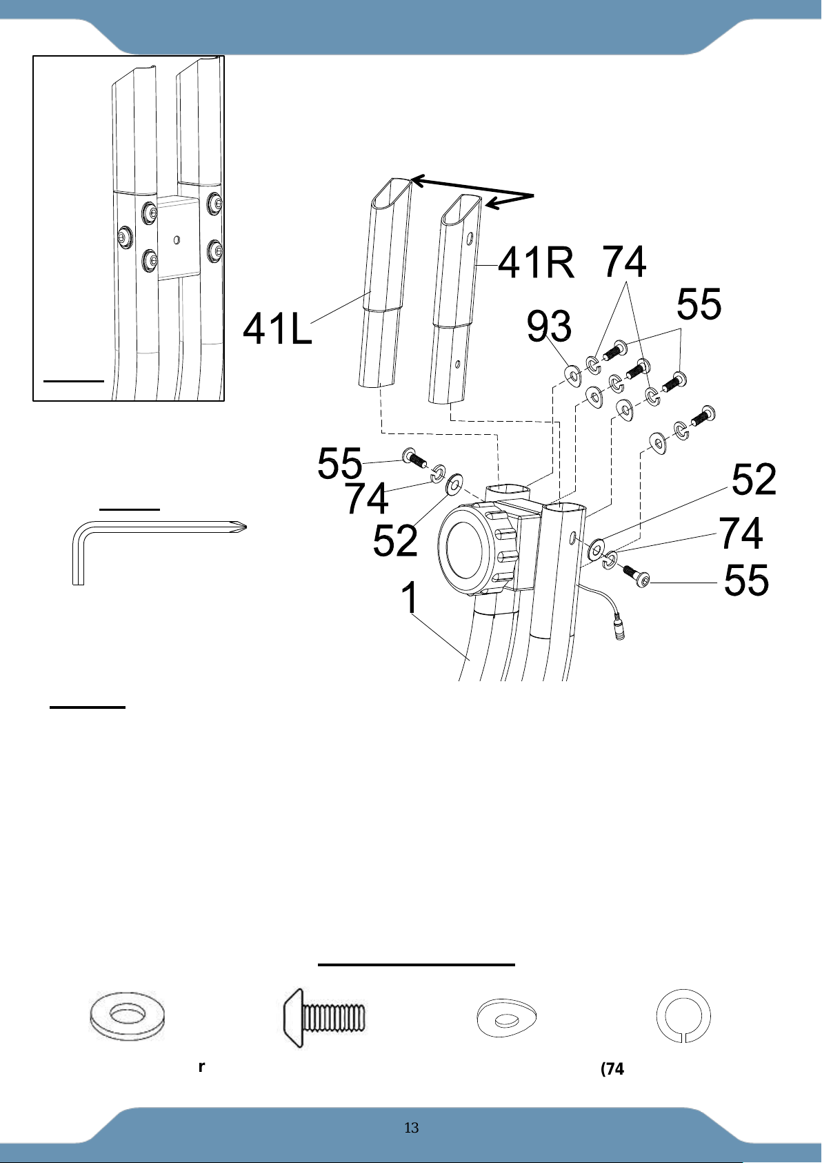
STEP 4
4A Installing The Handl ebar Extensions to the Rear Frame: Attach the Left & Right
Handlebar Extensions (41R) & (41L) to the Rear Frame (1). The Left & Right Handlebar
Extensions (41R) & (41L) can only be installed on their assigned side of the frame. Align the holes
and insert two Flat Washers (52), two Spring Washers (74), two Hex Bolts (55), four Curve
Washers (93), four Spring Washers(74) and four Hex Bolts (55). Tighten the Hex Bolts (55) with
the 5mm Allen Wrench with Phillips Screwdriver provided.
NOTE: See Fig. A for the appearance of the Extensions after installation.
NOTE:Please make sure the high cut of Left & Right Handlebar Extensions (41R) & (41L) are
facing forward.
5mm Allen Wrench
with Phillips Screwdriver
TOOL
ASSEMBLY
(52) Flat Washer
2PCS
2 PCS
(55) Hext Bolt
6 PCS
(74) Spring Washer
6 PCS
HARDWARE PACK
(93) Curve Washer
4PCS
high cut
Fig. A
14
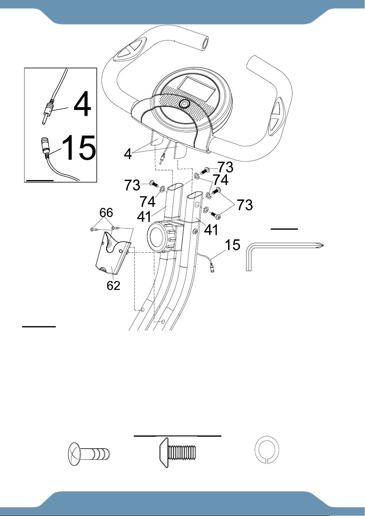
STEP 5
5A Installing The Handlebars: Attach the Handlebar (4) onto the top of the Handlebar
Extensions (41) with four Hex Bolts (73) and four Spring Washers (74). Tighten the Hex Bolts
(73) with the 5mm Allen Wrench with Phillips Screwdriver provided.
5B Connecting The Sensor Wires: Connect the female Sensor Wire (15) from the Rear Frame
(1) to the male wire from the Console (9). See Fig. B.
5C Installing The Bottle Holder: Attach the Bottle Holder (62) onto the Rear Frame (1) with two
Screws (66). Tighten the Screws (66) with the 5mm Allen Wrench with Phillips Screwdriver
provided.
ASSEMBLY
(66) Screw
2PCS
(73) Hex Bolt
4 PCS
(74) Spring Washer
4 PCS
HARDWARE PACK
5mm Allen Wrench with Phillips
Screwdriver
TOOL
Fig. B

15
SPECIFICATIONS:
TIME --------------------------------------- 0:00-99:59 MIN: SEC
SPEED ------------------------------------ 0.0-999.9 ML/H
DISTANCE ------------------------------- 0.0-999.9 ML
CALORIE --------------------------------- 0.0-999.9 KCAL
ODOMETER ----------------------------- 0.0-999.9 ML
PULSE ------------------------------------ 40-240 BEATS/MIN
CONSOLE FUNTIONS:
AUTO ON/OFF: The console will automatically turn on
when exercise is detected. If you leave the console idle for
4 minutes, the power will shut off automatically.
SCAN: Press the button until the screen displays SCAN;
the console will automatically scan the functions of TIME,
ODOMETER, CALORIE, PULSE, SPEED, and DISTANCE,
every 6 seconds.
TIME: Displays your elapsed workout time in minutes and seconds. The console will automatically
count up from 0:00 to 99:59 in one second intervals.
SPEED: Displays your workout speed in miles per hour.
DISTANCE: Displays the total distance traveled during each workout up to a maximum of 999.9
miles.
CALORIE: The console will estimate the cumulative calories burned at any given time during your
workout. The console will count up from 0.0 to 999.9 calories.
ODOMETER: Displays the total accumulative distance traveled during each workout up to a
maximum of 999.9 miles. The data values of the ODOMETER will not be reset to zero when
pressing and holding the button more than 2 seconds. If user takes out the batteries out from the
console, the ODOMETER data values will reset to zero.
PULSE: The console will display your pulse rate in beats per minute after holding both hands on
the handlebar grip sensors during exercise. To ensure the pulse readout is more precise, always
hold on to the handlebar grip sensors with two hands instead of one.
RESET: pressing and holding the button more than 2 seconds will reset all functional values to zero
except for the odometer data values.
HOW TO INSTALL THE BATTERIES:
1. Remove the battery cover at the rear of the console.
2. Place two "SIZE-AAA" batteries into the battery housing.
3. Ensure the batteries are correctly positioned and the battery springs are in proper contact with
the batteries.
4. Re-install the battery cover.
5. If the display is illegible or only partial legible, remove the batteries and wait 15 seconds before
reinstalling.
CONSOLE
16
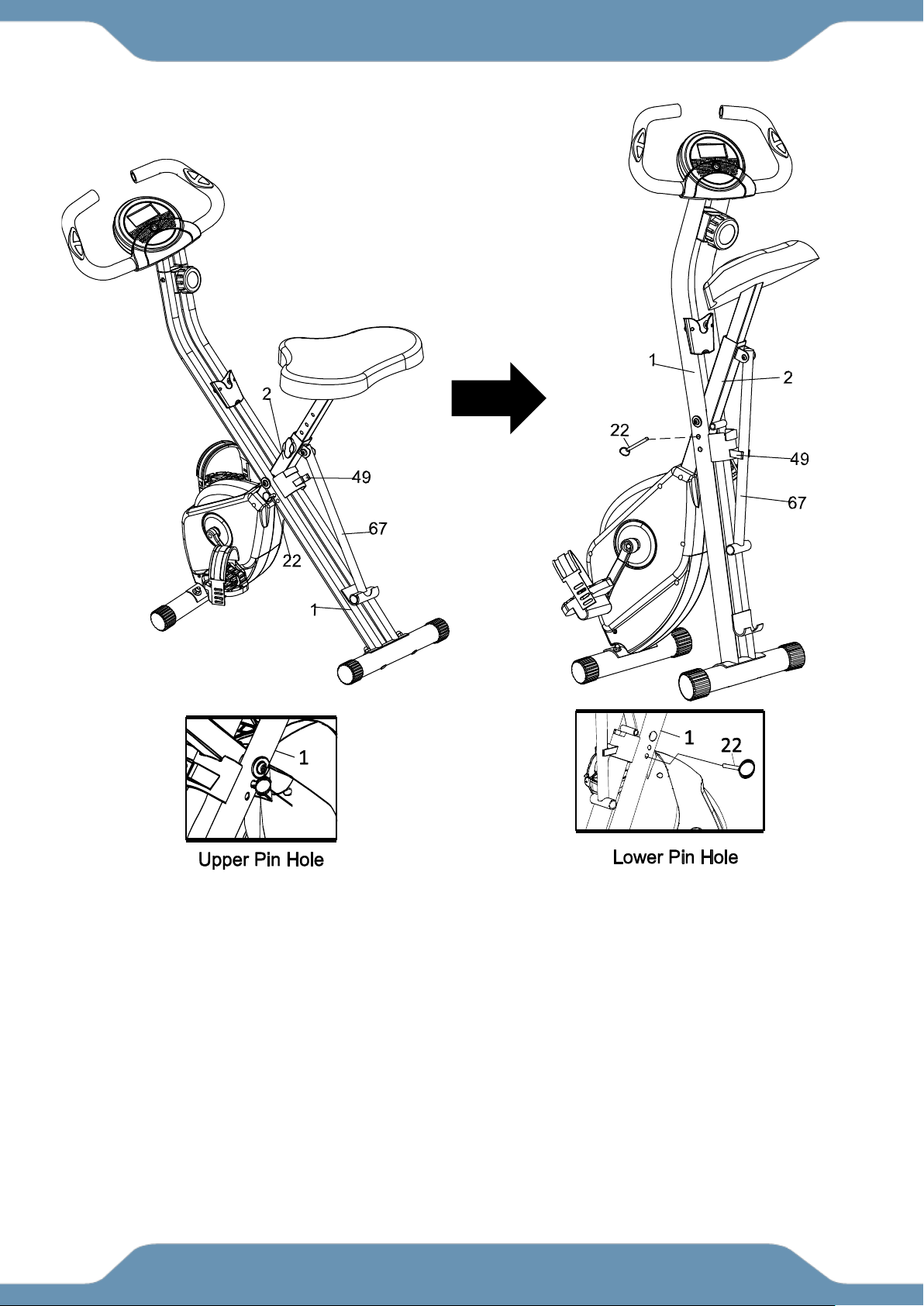
For your convenience, the bike can be folded up for storage.
1. Remove the Safety Pin (22) from the upper pin hole of the bike.
2. Fold the Rear Frame (1) and the Front Frame (2) together until the lower pin holes are
aligned.
3. Re-insert the Safety Pin (22) into the lower pin hole to secure the frames.
4. Lock the Support Tube (67) into the Support Tube Holder Clip (49).
STORAGE
17
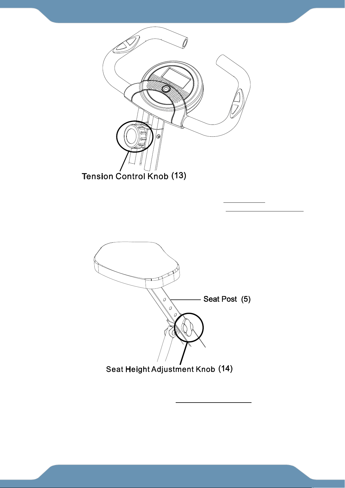
Adjusting the Tension Control Knob
To increase the tension, turn the Tension Control Knob (13) in a CLOCKWISE direction. ↻
To decrease the tension, turn the Tension Control Knob (13) in a COUNTERCLOCKWISE
direction. ↺
Adjusting the Seat Height
Turn the Seat Height Adjustment Knob (14) in a COUNTERCLOCKWISE direction until the Seat
Post (5) can be slid up or down. Then slide the Seat Post (5) up or down to a suitable position.
Lock the Seat Post (5) in place by tightening the Seat Height Adjustment Knob (14) in a
clockwise direction.
NOTE: When adjusting the height of the seat post, make sure the MAX line stamped on the
right side of the seat post does not pass the plastic bushing.
OPERATIONS & ADJUSTMENTS
18
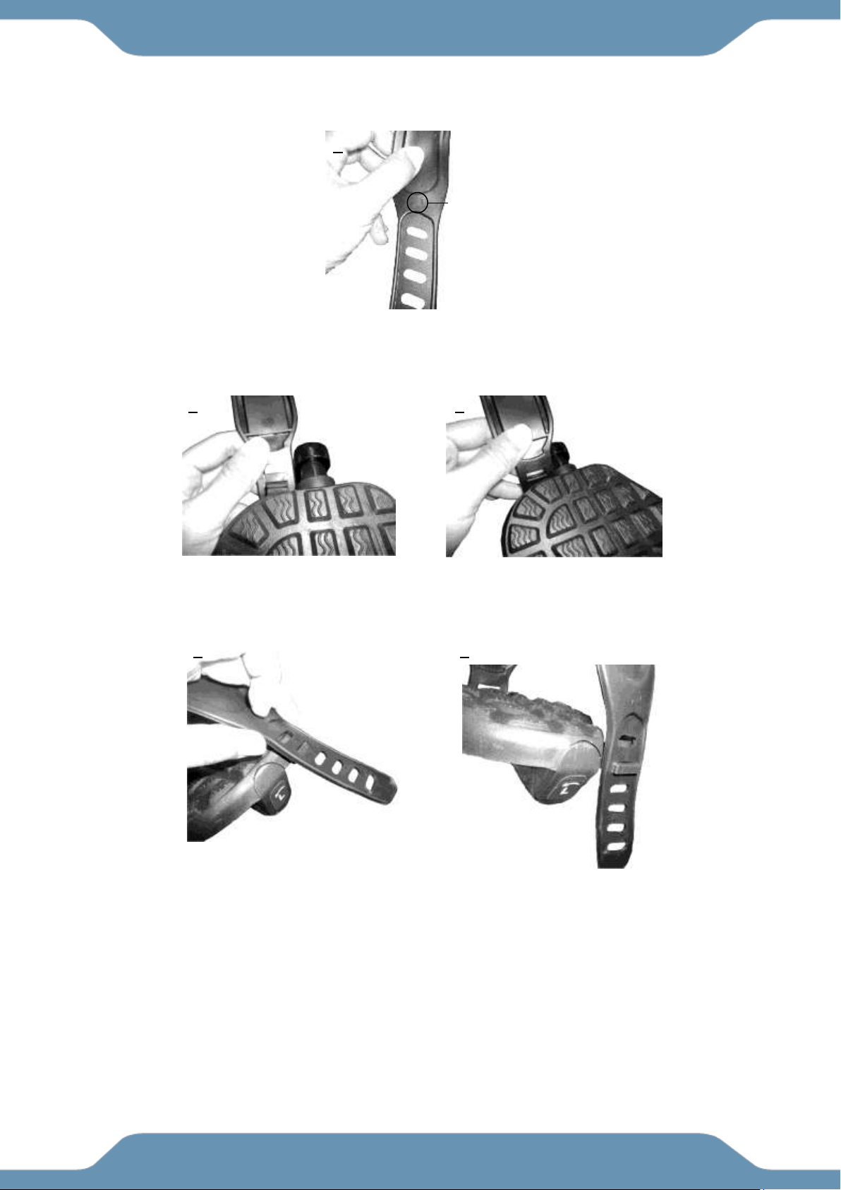
Adjusting the Pedal Strap
The Left Pedal Strap (88) is marked with an L on the strap. See Figure 1 .
Snap the three hole end onto the inside edge of the Left Pedal Strap (88) See Figure 2 & 3.
Select one of the adjustment holes which allow your foot to be easily removed
from the pedal. Snap the other end onto the outside edge of the Left Pedal Strap (88) with the L
mark on the strap. See Figures 4 and 5.
Use the same procedure to snap the Right Pedal Strap (89) onto the right pedal.
3
2
4
5
1
L mark
OPERATIONS & ADJUSTMENTS
19
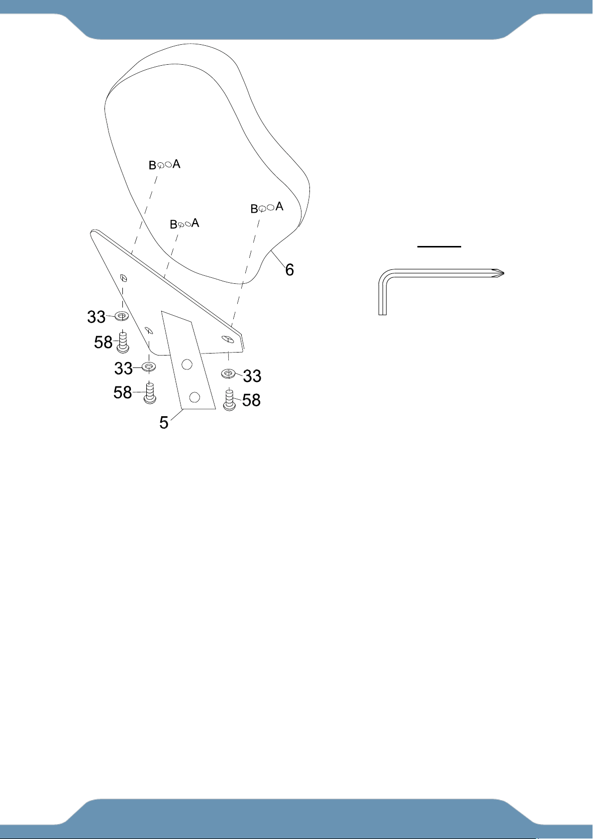
Seat Cushion Adjustment
The Seat Cushion (6) can be adjusted for users of different heights.
Adjust the Seat Cushion (6) to the B position for people whose height is between 5’1” to 5’6”.
Assemble the Seat Cushion (6) and align the bolt holes on the underside of Seat Cushion (6) with
the holes on top of the Seat Post (5). Then attach it with three Flat Washers (33) and three
Hexagon Socket Bolts (58). Tighten the bolts with the 5mm Allen Wrench with Phillips
Screwdriver provided.
Adjust the Seat Cushion (6) to the A position for people whose height is between 5’7” to 6’3”.
Assemble the Seat Cushion (6) and align the bolt holes on the underside of the Seat Cushion (6)
with the holes on top of the Seat Post (5), Then attach it with three Flat Washers (33) and three
Hexagon Socket Bolts (58). Tighten bolts with the 5mm Allen Wrench with Phillips
Screwdriver provided.
OPERATIONS & ADJUSTMENTS
5mm Allen Wrench with Phillips
Screwdriver
TOOL
20
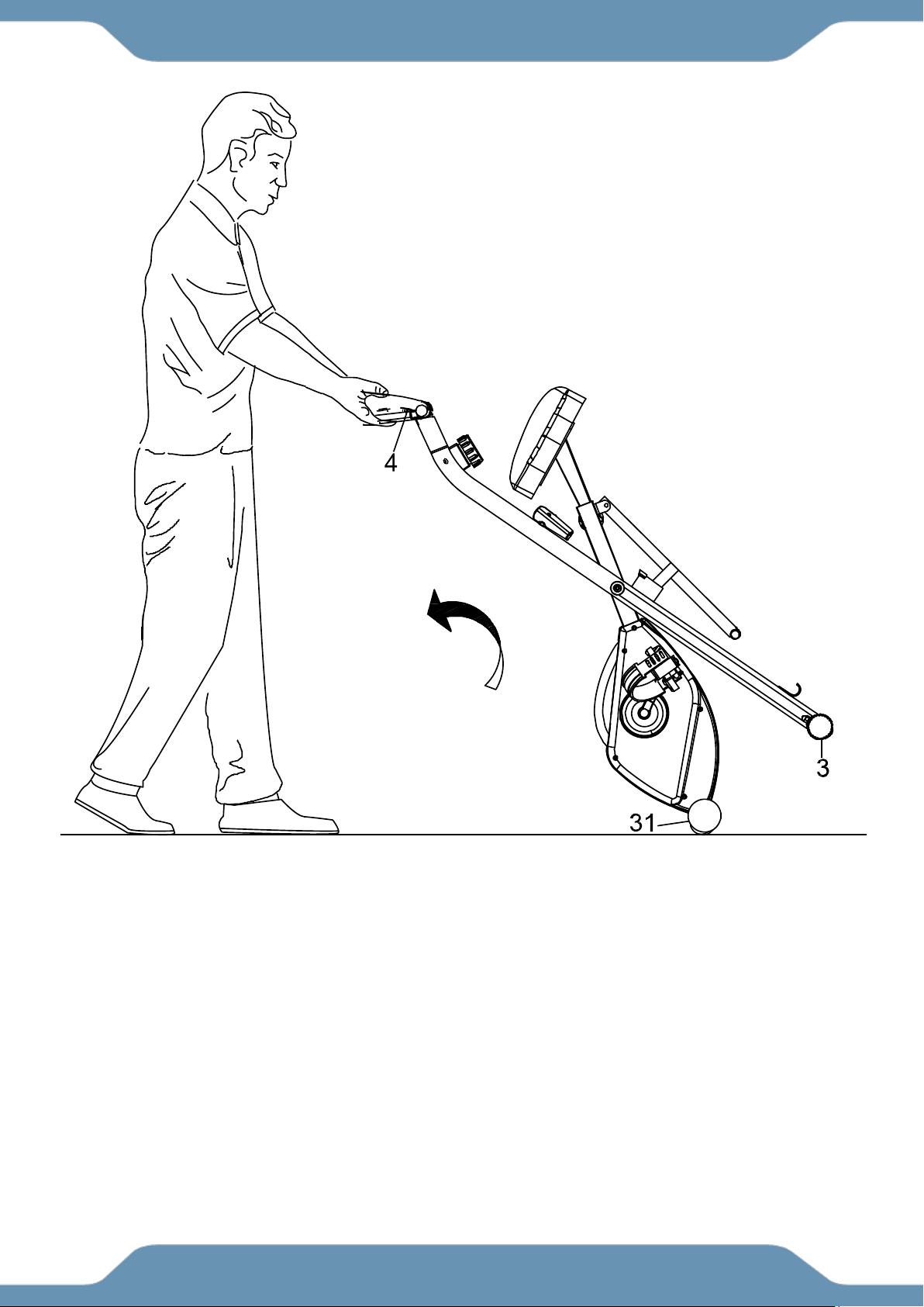
Transporting the Bike
Hold the Handlebar (4) and pull the machine until the Wheels on the Front Stabilizer (31) make
contact with the floor. Push or pull the unit to the desired location, then gently lower the Rear
Stabilizer (3) to the ground.
TRANSPORTATION

21
MAINTENANCE
Cleaning
The bike can be cleaned with a soft clean damp cloth. Do not use abrasives or solvents on the
plastic parts. Wipe your perspiration off the bike after each use. Be careful not to get excessive
moisture on the console display panel as this might cause an electrical hazard or electronics to fail.
Keep the bike, especially the console console out of direct sunlight to prevent screen damage.
Inspect all of the assembly bolts, nuts, screws, and pedals on the machine for proper tightness
every week.
Storage
Store the bike in a clean and dry environment away from children and pets.
TROUBLE SHOOTING
PROBLEM: There is no display on the console.
SOLUTION: Remove the console and verify the wires that come from the console are properly
connected to the wires that come from the frame.
SOLUTION: Check if the batteries are correctly positioned and the battery springs are in proper
contact with the batteries.
SOLUTION: The batteries in the console may be dead. Replace the dead batteries with new
batteries.
PROBLEM: There is no heart rate reading or the heart rate reading is erratic or inconsistent.
SOLUTION: Make sure that the wire connections for the hand pulse sensors are
securely connected.
SOLUTION: To ensure the pulse readout is precise, always hold on to the handlebar grip sensors
with two hands.
SOLUTION: Avoid gripping the hand pulse sensors too tightly. Try to maintain moderate pressure
while holding onto the hand pulse sensors.
MAINTENANCE & TROUBLESHOOTING

22
MANUFACTURER’S LIMITED WARRANTY
Paradigm Health & Wellness warrants to the original purchaser that this product is free from
defects in material and workmanship when used for the purpose intended, under the
conditions that it has been installed and operated in accordance with Paradigm’s Owner’s
Manual. Paradigm’s obligation under this warranty applies to the following:
COMPONENT LENGTH OF WARRANTY
Structural Frame 1 year For Home Use Only
All Other Components 90 days For Home Use Only
(console display, electronics, upholstery, foam, ball bearings, pulleys, belts, cables, wires,
shocks, covers, tension, internal mechanism, wheels, pedals, knobs, accessories and
hardware)
Exclusions from Warranty Coverage:
Paradigm does not warrant against and is not responsible for, and no implied warranty shall be deemed to cover, any
product failure, product malfunction, or damages attributable to:
1. Improper installation and/or failure to abide by Paradigm’s installation guidelines;
2. Use of this product beyond normal home use, or in an application for which it was not designed;
3. Cosmetic items such as scratches, dents or discolorations;
4. Damage caused by normal wear and tear, vandalism, accidental, and by animals;
5. Any act of Nature (such as fire, flooding, snow, ice, hurricane, earthquake, lightning or other natural disaster),
environmental condition (such as air pollution, mold, mildew, etc.), or staining from foreign substances (such as dirt,
grease, oil, etc.);
6. Normal weathering due to exposure to sunlight, weather and atmosphere which can cause colored surfaces to,
among other things, flake, chalk, accumulate dirt or stains.
7. Improper operation, alteration, handling, storage, abuse or neglect of the products.
Paradigm, using its sole discretion, will either repair or replace free of charge any part(s)
proven to be defective under normal home use. Any repair or replacement shall provide no
new warranty coverage, but shall retain only the remaining portion of the original product’s
warranty. This warranty is offered only to the original purchaser and is not transferable.
Proof of original purchase is required.
Ordering Replacement Parts
Replacement parts can be ordered by emailing our customer service department:
Service@paradigmhw.com
Open Monday thru Friday 8:00 AM - 5:00 PM (PST).
When ordering replacement parts please have the following information ready:
1. Owner’s Manual
2. Model Number
3. Description of Parts
4. Part Number
5. Date of Purchase
WARRANTY

23
Paradigm Health & Wellness, Inc.
EMAIL THIS FORM WITH YOUR RECEIPT OF PURCHASE TO
Service@paradigmhw.com *
NAME:_____________________________________________________________________________________
ADDRESS:__________________________________________________________________________________
CITY:________________________ STATE:_____________ ZIP:_______________________________________
TELEPHONE: (Day)________________________________________________________________________
(Night)_______________________________________________________________________
SERIAL#:___________________________________________________________________________________
MODEL#:___________________________________________________________________________________
PURCHASE DATE:___________________________________________________________________________
PLACE OF PURCHASE:_______________________________________________________________________
“YOUR ORDER WILL BE PROCESSED WITHIN 3 BUSINESS DAYS”
* This form can also be faxed in Fax #: 626-810-2166
PART #
DESCRIPTION
QTY
PARTS REQUEST FORM


