USER’S MANUAL
Serial Number
Decal
CAUTION
Read all precautions and
instructions in this manual before
using this equipment. Keep this
manual for future reference.
Model No. VMEX82018.0
Serial No.
Write the serial number in the space
above for reference.
freemotionfitness.com
QUESTIONS?
If you have questions, or if
parts are damaged or missing,
please see HOW TO CONTACT
CUSTOMER CARE on the back
cover of this manual.
2
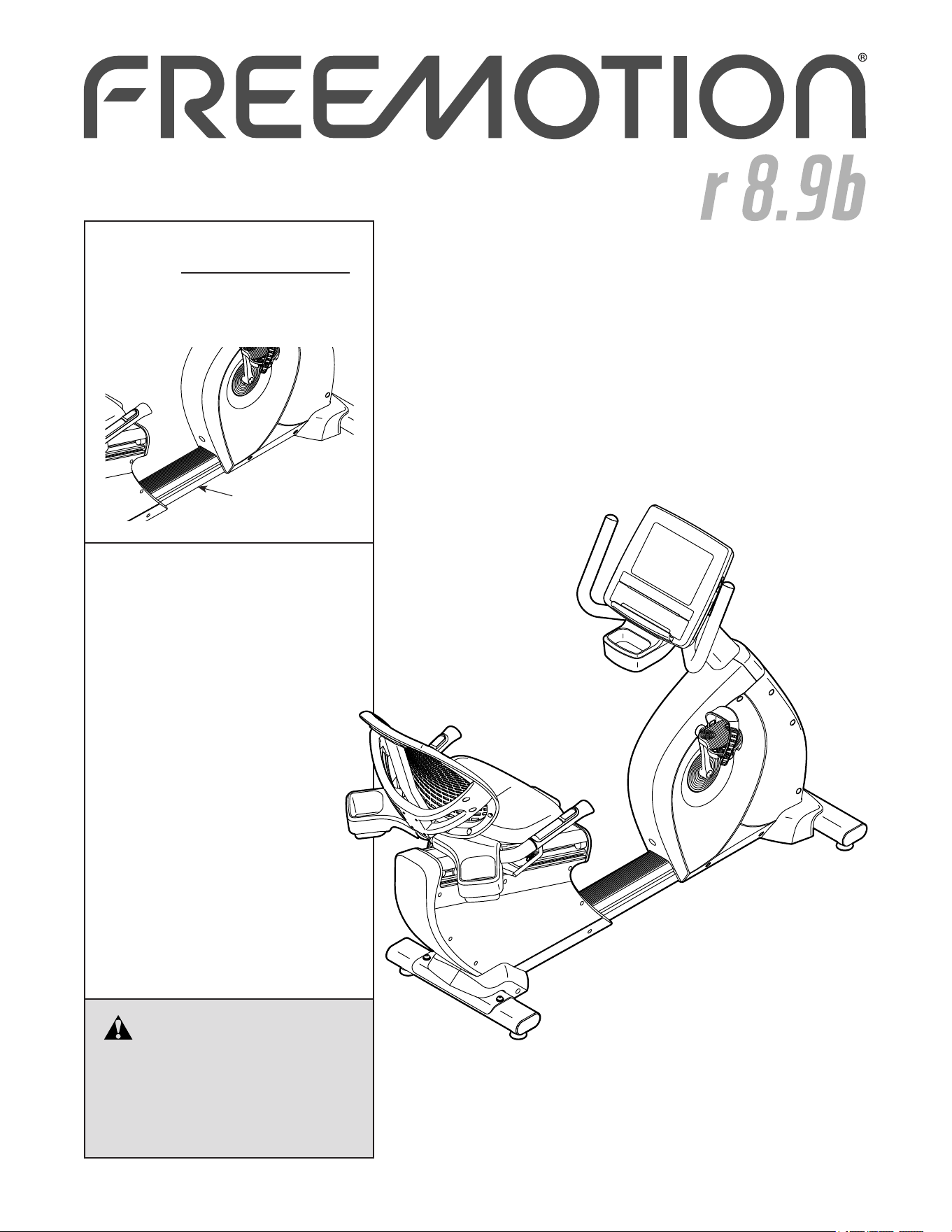
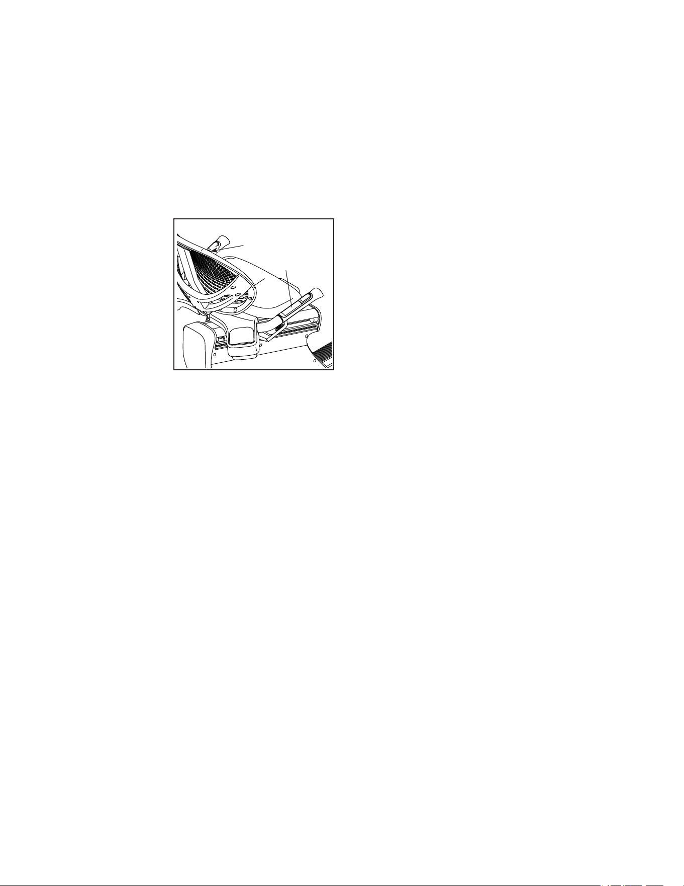
This drawing shows the location(s) of the warning
decal(s). If a decal is missing or illegible, see
the back cover of this manual and request a
free replacement decal. Apply the decal in the
location shown. Note: The decal(s) may not be
shown at actual size.
TABLE OF CONTENTS
WARNING DECAL PLACEMENT
WARNING DECAL PLACEMENT . . . . . . . . . . . . . . . . . . . . . . . . . . . . . . . . . . . . . . . . . . . . . . . . . . . . . . . . . . . . . . .2
IMPORTANT PRECAUTIONS ..................................................................3
BEFORE YOU BEGIN. . . . . . . . . . . . . . . . . . . . . . . . . . . . . . . . . . . . . . . . . . . . . . . . . . . . . . . . . . . . . . . . . . . . . . . .4
PART IDENTIFICATION CHART. . . . . . . . . . . . . . . . . . . . . . . . . . . . . . . . . . . . . . . . . . . . . . . . . . . . . . . . . . . . . . . .5
ASSEMBLY . . . . . . . . . . . . . . . . . . . . . . . . . . . . . . . . . . . . . . . . . . . . . . . . . . . . . . . . . . . . . . . . . . . . . . . . . . . . . . . .6
HOW TO UPGRADE THE CONSOLE ..........................................................14
HOW TO USE THE EXERCISE BIKE. . . . . . . . . . . . . . . . . . . . . . . . . . . . . . . . . . . . . . . . . . . . . . . . . . . . . . . . . . .15
COMPLIANCE INFORMATION. . . . . . . . . . . . . . . . . . . . . . . . . . . . . . . . . . . . . . . . . . . . . . . . . . . . . . . . . . . . . . . .24
MAINTENANCE AND TROUBLESHOOTING ....................................................25
EXERCISE GUIDELINES ....................................................................26
PART LIST. . . . . . . . . . . . . . . . . . . . . . . . . . . . . . . . . . . . . . . . . . . . . . . . . . . . . . . . . . . . . . . . . . . . . . . . . . . . . . . .27
EXPLODED DRAWING. . . . . . . . . . . . . . . . . . . . . . . . . . . . . . . . . . . . . . . . . . . . . . . . . . . . . . . . . . . . . . . . . . . . . .29
HOW TO CONTACT CUSTOMER CARE . . . . . . . . . . . . . . . . . . . . . . . . . . . . . . . . . . . . . . . . . . . . . . . . Back Cover
LIMITED WARRANTY. . . . . . . . . . . . . . . . . . . . . . . . . . . . . . . . . . . . . . . . . . . . . . . . . . . . . . . . . . . . . . . Back Cover
FREEMOTION and IFIT are registered trademarks of ICON Health & Fitness, Inc. App Store is a trademark of
Apple Inc., registered in the U.S. and other countries. Android and Google Play are trademarks of Google LLC.
The Bluetooth
®
word mark and logos are registered trademarks of Bluetooth SIG, Inc. and are used under license.
IOS is a trademark or registered trademark of Cisco in the U.S. and other countries and is used under license.
POLAR is a registered trademark of Polar Electro Oy.

3
IMPORTANT PRECAUTIONS
WARNING: To reduce the risk of burns, fire, electric shock, or injury to persons, read all
important precautions and instructions in this manual and all warnings on your exercise bike before
using your exercise bike. Freemotion Fitness assumes no responsibility for personal injury or prop-
erty damage sustained by or through the use of this product.
1. It is the responsibility of the owner to ensure
that all users of the exercise bike are ade-
quately informed of all precautions.
2. Before beginning any exercise program,
consult your physician. This is especially
important for persons over age 35 or per-
sons with pre-existing health problems.
3. Use the exercise bike only as described in
this manual.
4. Keep the exercise bike indoors, away from
moisture and dust. Do not put the exercise
bike in a garage or covered patio, or near
water.
5. Place the exercise bike on a level surface
with at least 2 ft. (0.6 m) of clearance around
the exercise bike. To protect the floor or
carpet from damage, place a mat under the
exercise bike.
6. Inspect and properly tighten all parts each
time the exercise bike is used. Replace any
worn parts immediately.
7. Keep children under age 13 and pets away
from the exercise bike at all times.
8. Wear appropriate clothes while exercising;
do not wear loose clothes that could become
caught on the exercise bike. Always wear
athletic shoes for foot protection.
9. The exercise bike should not be used
by persons weighing more than 400 lbs.
(181 kg).
10. Be careful when mounting and dismounting
the exercise bike.
11. The heart rate monitor is not a medical
device. Various factors, including the user’s
movement, may affect the accuracy of heart
rate readings. The heart rate monitor is
intended only as an exercise aid in determin-
ing heart rate trends in general.
12. Always keep your back straight while using
the exercise bike; do not arch your back.
13. Over exercising may result in serious injury
or death. If you feel faint, if you become short
of breath, or if you experience pain while
exercising, stop immediately and cool down.
4
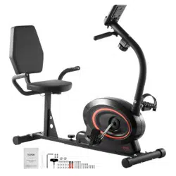
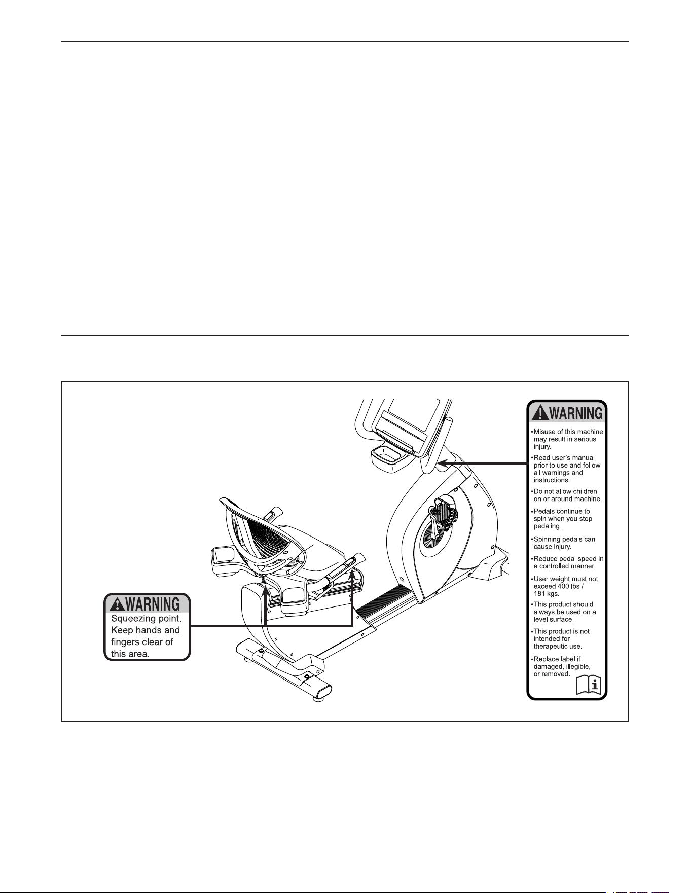
Heart Rate Monitor
Resistance Control
Seat Handle
Console
Handlebar
Resistance Control
Leveling Foot
Wheel
Seat
Small Accessory Tray
Large Accessory Tray
Thank you for selecting the revolution-
ary FREEMOTION
®
R8.9B exercise bike. The
R8.9B exercise bike provides an impressive selection
of features designed to make your workouts more
effective and enjoyable.
For your benefit, read this manual carefully before
you use the exercise bike. If you have questions after
reading this manual, please see the back cover of this
manual. To help us assist you, note the product model
number and serial number before contacting us. The
model number and the location of the serial number
decal are shown on the front cover of this manual.
Before reading further, please familiarize yourself with
the parts that are labeled in the drawing below.
BEFORE YOU BEGIN
Backrest
Length: 5 ft. 10 in. (178 cm)
Width: 2 ft. (61 cm)
Weight: 205 lbs. (93 kg)
5
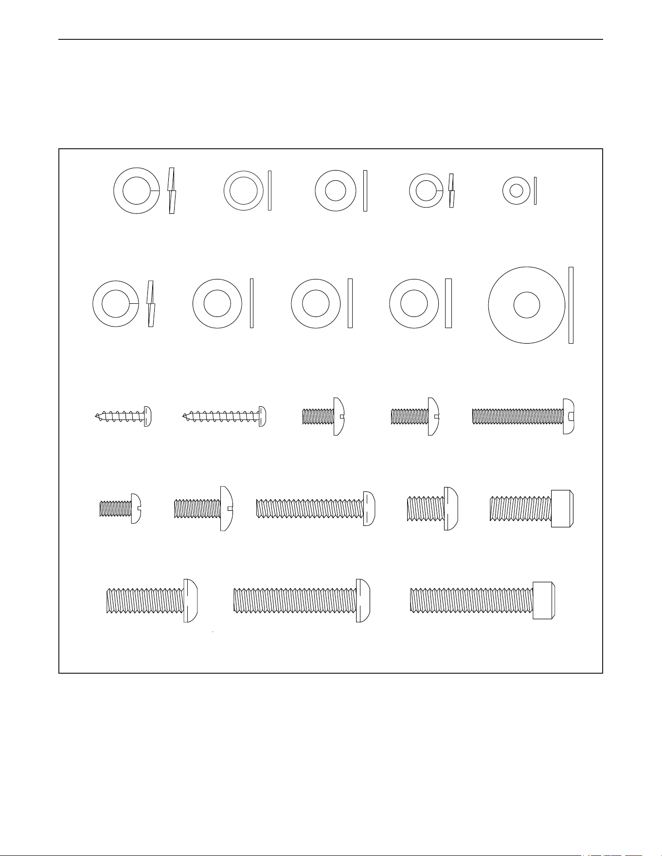
M4 Washer
(114)–2
M8 x 12mm x
1mm Washer
(92)–4
M6 Split
Washer
(96)–4
M6 x 1mm
Washer
(97)–4
M8 Split
Washer
(77)–10
M5 x 12mm
Screw (78)–5
M5 x 10mm
Truss Screw
(81)–4
M4 x 25mm
Screw (94)–2
M5 x 30mm
Screw (88)–2
M4 x 16mm
Self-tapping
Screw (101)–4
M8 Bright Split
Washer
(148)–1
M8 x 16mm x
1mm Washer
(80)–4
M8 x 16mm x
1.5mm Washer
(110)–4
M8 x 16mm x
2mm Washer
(143)–2
M8 x 25mm x
1.5mm Washer
(142)–1
M8 x 40mm Screw
(105)–1
M8 x 25mm Screw
(138)–4
M8 x 40mm Cap
Screw (145)–2
M8 x 20mm
Screw (93)–4
M6 x 35mm
Screw (95)–4
M8 x 12mm Seat
Screw (125)–4
M6 x 15mm
Screw (128)–4
M5 x 10mm
Screw (89)–6
PART IDENTIFICATION CHART
Use the drawings below to identify the small parts needed for assembly. The number in parentheses below each
drawing is the key number of the part, from the PART LIST near the end of this manual. The number following the
key number is the quantity needed for assembly. Note: If a part is not in the hardware kit, check to see if it
has been preassembled. Extra parts may be included.
6
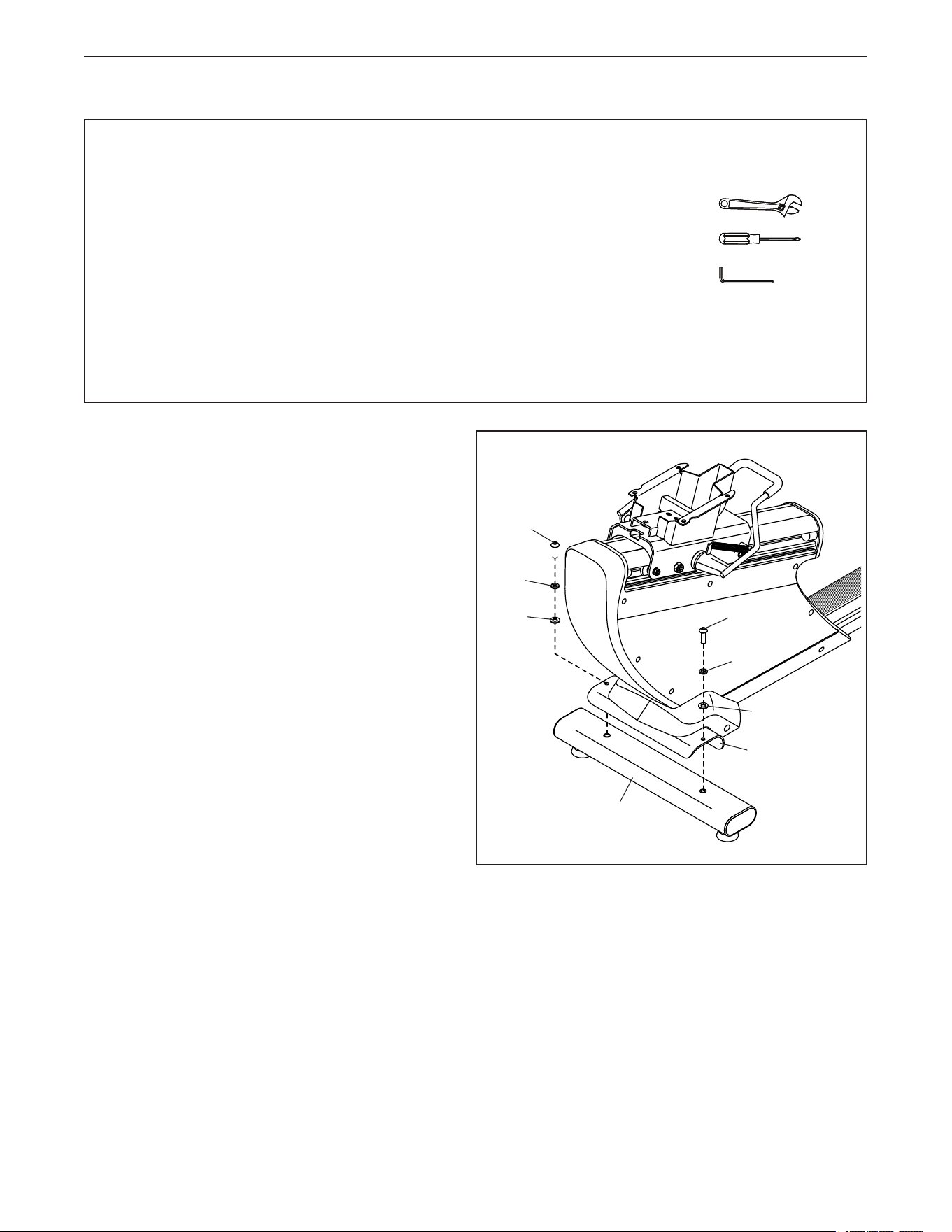
• Assembly requires two persons.
• Place all parts in a cleared area and remove the
packing materials. Do not dispose of the packing
materials until you nish all assembly steps.
• If a part is not in the hardware kit, check to see if
it has been preassembled.
• Left parts are marked “L” or “Left” and right parts
are marked “R” or “Right.”
• To identify small parts, see page 5.
• The following tools (not included) are required for
assembly:
one adjustable wrench
one Phillips screwdriver
a set of metric hex keys
Assembly may be easier if you have a set of
wrenches. To avoid damaging parts, do not use
power tools.
ASSEMBLY
1
1. Identify the Rear Stabilizer (37), which does not
have wheels, and orient it as shown.
Attach the Rear Stabilizer (37) to the Frame (1)
with two M8 x 25mm Cap Screws (138), two
M8 Split Washers (77), and two M8 x 16mm x
1.5mm Washers (110).
138
77
77
110
37
1
110
138
7
3. Orient the Large Accessory Tray (52) and the
Seat Frame (18) as shown.
Tip: Avoid pinching the wires. Attach the Large
Accessory Tray (52) to the Seat Frame (18) with
four M4 x 16mm Self-tapping Screws (101); start
all the Self-tapping Screws, and then tighten
them.
3
2
2
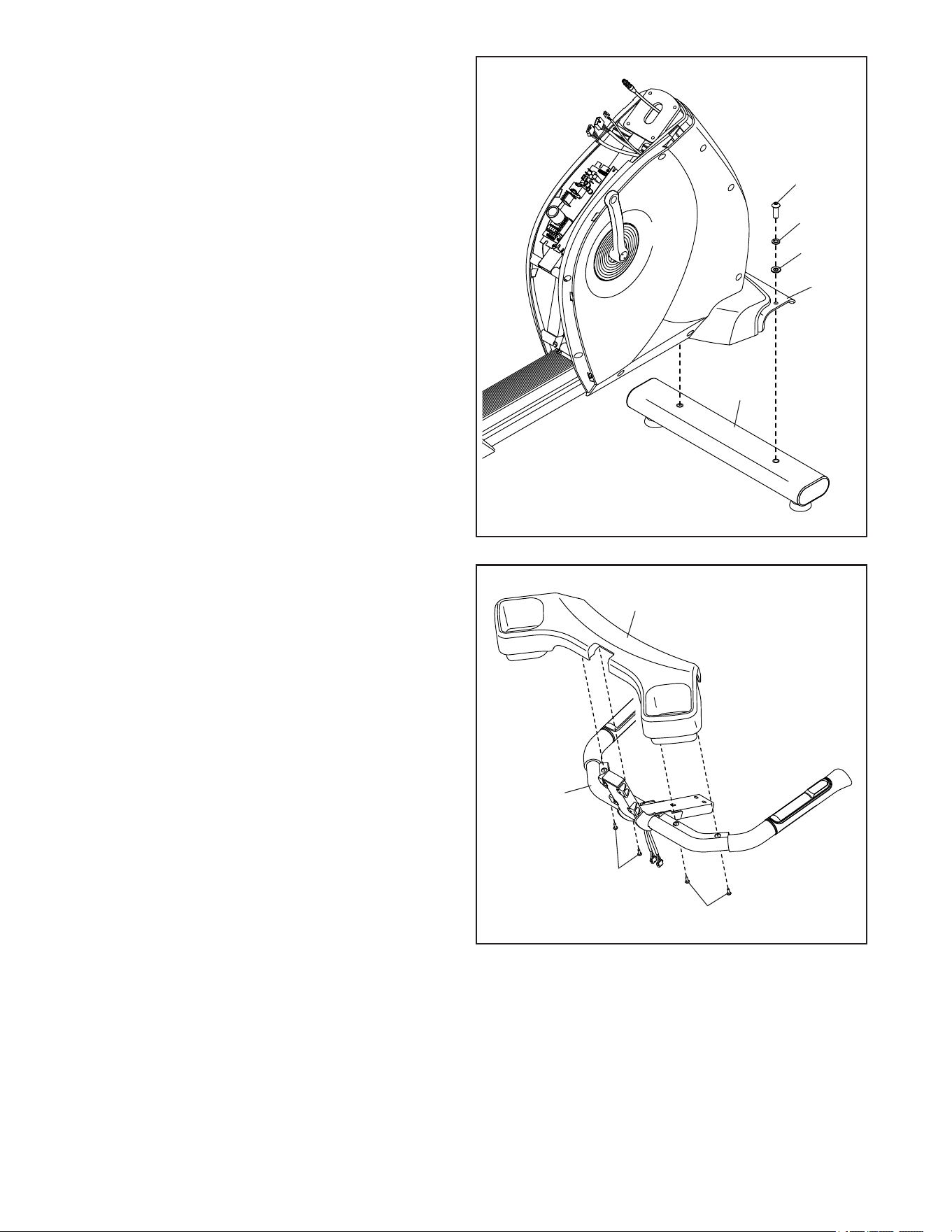
2. Attach the Front Stabilizer (50) to the Frame
(1) with two M8 x 25mm Cap Screws (138), two
M8 Split Washers (77), and two M8 x 16mm x
1.5mm Washers (110) (only one side is shown).
77
110
138
50
52
18
101
101
1
Avoid pinching
the wires
8
4
4. While a second person holds the Seat Frame
(18) near the Seat Carriage (11), connect the
wires (A) in the Seat Frame to the wires (B) in
the Seat Carriage. Insert the excess wire into the
Seat Carriage.
Tip: Avoid pinching the wires. Attach the Seat
Frame (18) to the Seat Carriage (11) with an
M8 x 40mm Screw (105), an M8 Bright Split
Washer (148), and an M8 x 25mm x 1.5mm
Washer (142); do not fully tighten the Screw
yet.
Finish attaching the Seat Frame (18) with two
M8 x 40mm Cap Screws (145), two M8 Split
Washers (77), and two M8 x 16mm x 2mm
Washers (143); fully tighten the M8 x 40mm
Cap Screws (145) and the M8 x 40mm
Screw (105).
5
5. Attach the Seat Frame Plate (35) to the Seat
Carriage (11) with four M8 x 12mm Seat Screws
(125), four M8 Split Washers (77), and four
M8 x 16mm x 1mm Washers (80) (only one side
is shown); start all the Seat Screws, and then
tighten them.
18
35
80
77
125
11
11
A
B
142
77
105
145
143
Avoid pinching
the wires
148
9
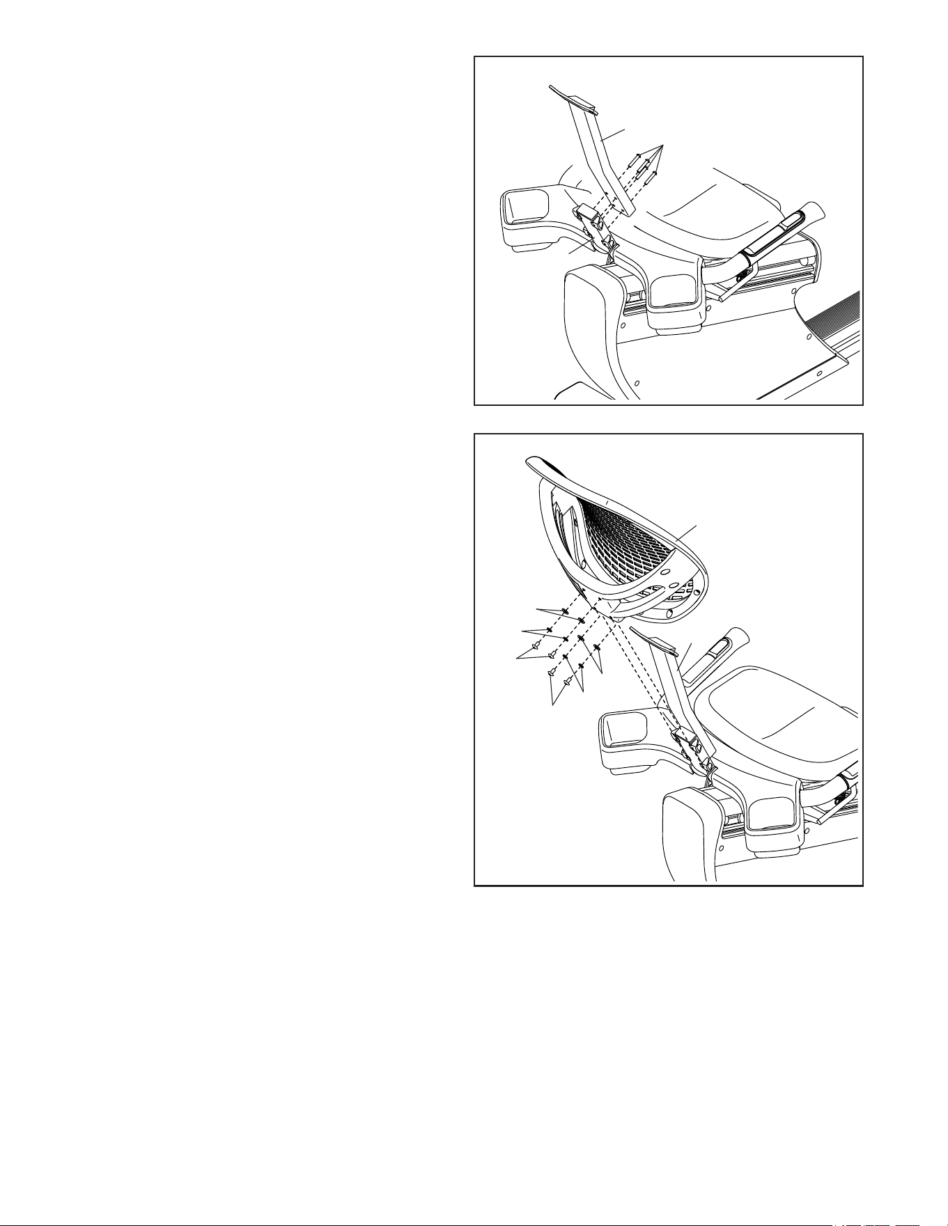
6. Attach the Backrest Frame (14) to the Seat
Frame (18) with four M6 x 35mm Screws (95);
do not fully tighten the Screws yet.
6
7
7. Slide the Backrest (13) onto the Backrest
Frame (14).
Attach the Backrest (13) to the Backrest Frame
(14) with four M6 x 15mm Screws (128), four M6
Split Washers (96), and four M6 x 1mm Washers
(97); start all the Screws, and then tighten
them.
See step 6. Tighten the M6 x 35mm
Screws (95).
14
18
95
97
97
96
96
14
13
128
128
10
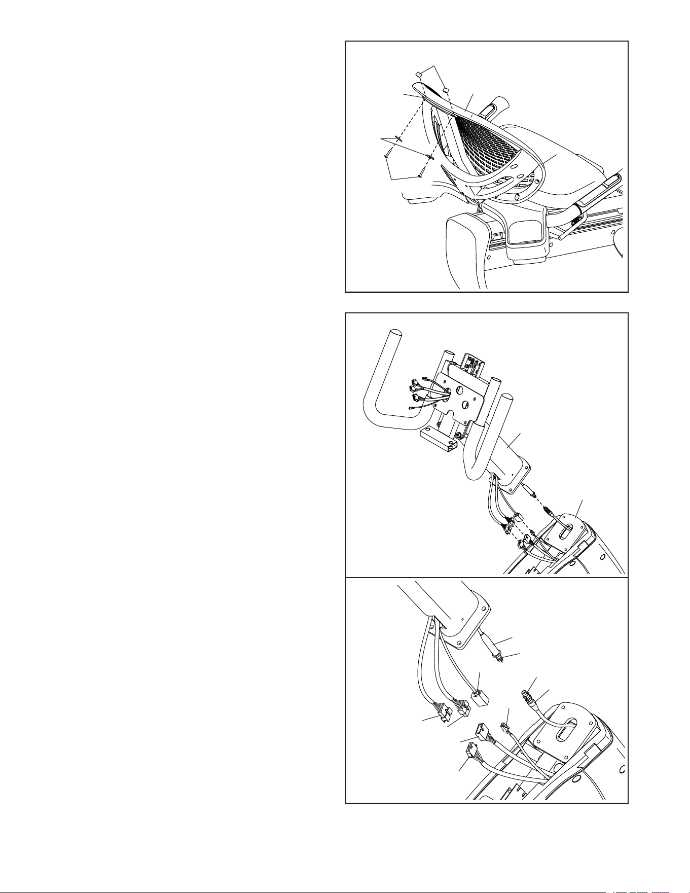
8
8. Attach the top of the Backrest (13) to the
Backrest Frame (14) with two M4 x 25mm
Screws (94), two M4 Washers (114), and two
Backrest Spacers (39).
9
9. Have a second person hold the Upright (4) near
the Frame (1).
See the lower drawing. Connect the Upper
Main Wire (79) to the Lower Main Wire (123),
connect the Upper Power Wire (115) to the
Lower Power Wire (122), connect the Upper
Pulse Wire (99) to the Lower Pulse Wire (124),
and connect the Upper TV Coaxial Cable (100)
to the Lower TV Coaxial Cable (121).
See the lower drawing. Locate the covers
(C, D) on the Lower TV Coaxial Cable (121) and
on the Upper TV Coaxial Cable (100). Slide the
covers together and push the small cover (C)
into the large cover (D).
Then, insert the excess wire into the Upright (4).
13
14
39
114
94
4
1
D
C
79
123
100
121
115
99
124
122
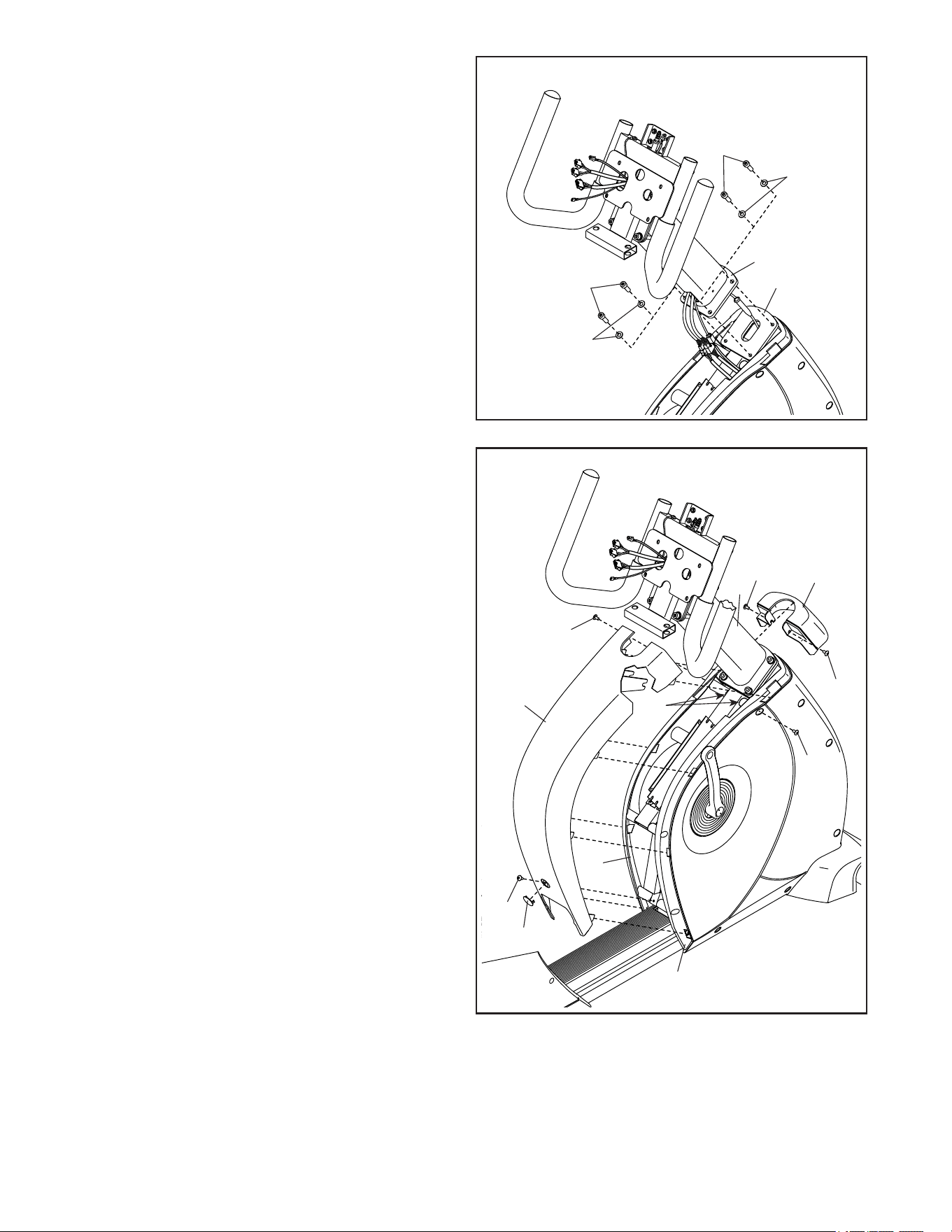
11
11
10
10. Tip: Avoid pinching the wires. Attach the
Upright (4) to the Frame (1) with four M8 x 20mm
Screws (93) and four M8 x 12mm x 1mm
Washers (92); start all the Screws, and then
tighten them.
Avoid pinching
the wires
1
93
92
92
93
4
20
19
78
78
78
78
78
73
22
4
21
11. Attach the Front Shield Cap (19) to the Upright
(4) with two M5 x 12mm Screws (78); start both
Screws, and then tighten them.
Tip: Avoid pinching the wires. Press the Front
Shield Cover (20) onto the Left and Right Front
Shields (21, 22); make sure that the forks on
the underside of the Front Shield Cover are
inserted into the indicated slots (E) on the
exercise bike.
Next, remove the Screw Cap (73) from the Front
Shield Cover (20).
Attach the Front Shield Cover (20) with three
M5 x 12mm Screws (78); start all the Screws,
and then tighten them.
Then, press the Screw Cap (73) back into the
Front Shield Cover (20).
E
12
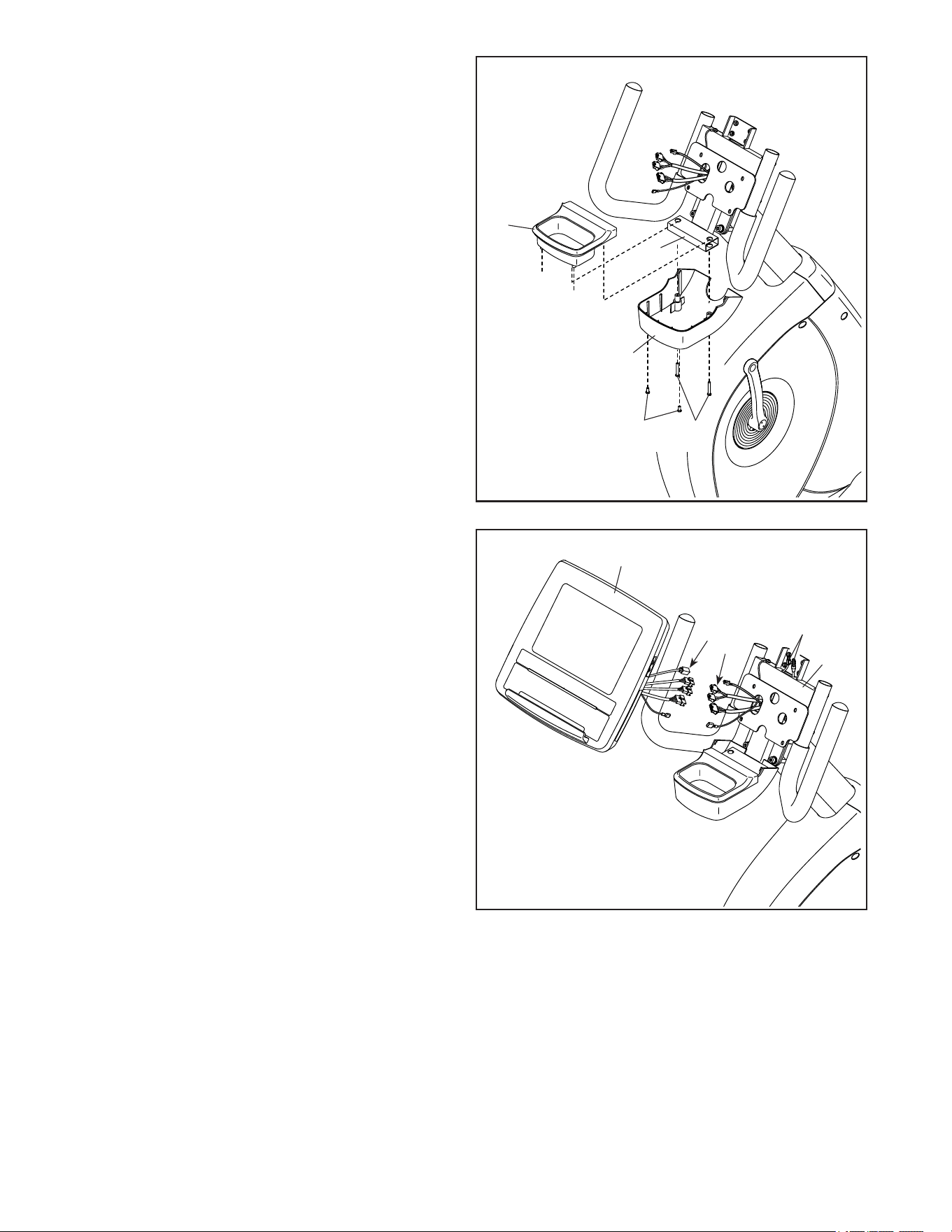
12
13
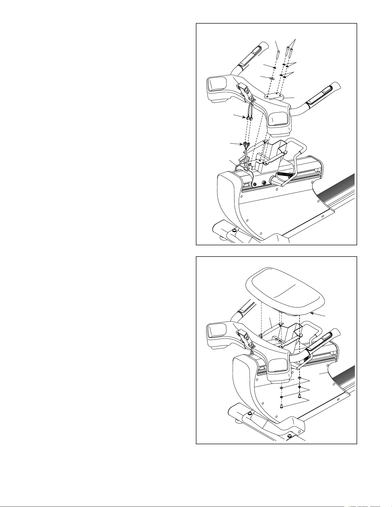
12. Attach the Small Accessory Tray (9) and the
Accessory Tray Cover (42) to the Handlebar
(47) with two M5 x 30mm Screws (88) and two
M5 x 10mm Screws (89); start all the Screws,
and then tighten them.
13. While a second person holds the Console (5)
near the Handlebar (47), connect the wires (f)
on the Console to the matching wires (g) in the
Handlebar.
Insert the excess wire downward through the
Handlebar (47).
Note: The indicated wires (H) will not be used
unless you purchase the optional digital TV
(see HOW TO UPGRADE THE CONSOLE on
page 14).
88
5
F
G
H
47
89
42
9
47
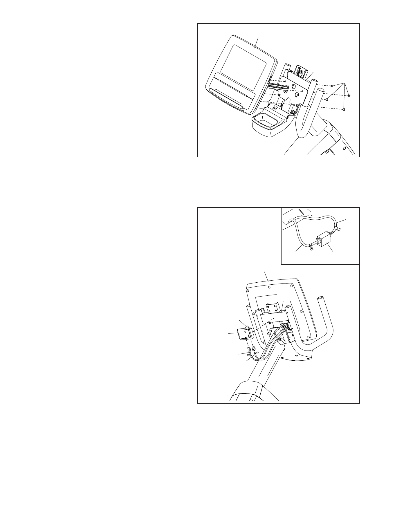
13
15
14
14. Tip: Avoid pinching the wires. Attach the
Console (5) to the Handlebar (47) with four
M5 x 10mm Truss Screws (81); start all the
Truss Screws, and then tighten them.
81
J
J
K
K
I
L
M
Avoid pinching
the wires
5
5
47
15. Look at the back of the Console (5) and locate
the coupler (I) that has a wire labeled “In” (J) and
a wire labeled “Out” (K).
See the inset drawing. Unplug the wire labeled
"In" (J) and the wire labeled "Out" (K) from the
coupler (I), and discard the coupler.
Then, plug the wire labeled “In” (J) into the
“In” port on the receiver (L), and plug the wire
labeled “Out” (K) into the “Out” port on the
receiver.
Next, peel the backing (M) off the receiver (L),
and press the receiver onto the Handlebar (47)
in the location shown.
Follow the instructions included with the
MYE programmer to program the receiver.
If you purchased the optional MYE receiver to set up a wall of TVs, go to step 15 to install the receiver.
If you did not purchase the optional MYE receiver, go to step 16. To order the optional MYE receiver, see
the back cover of this manual.
47
14
16
17
18. After the exercise bike is assembled, inspect it to make sure that it is assembled correctly and that it
functions properly. Make sure that all parts are properly tightened before you use the exercise bike.
Extra parts may be included. Place a mat under the exercise bike to protect the floor or carpet.
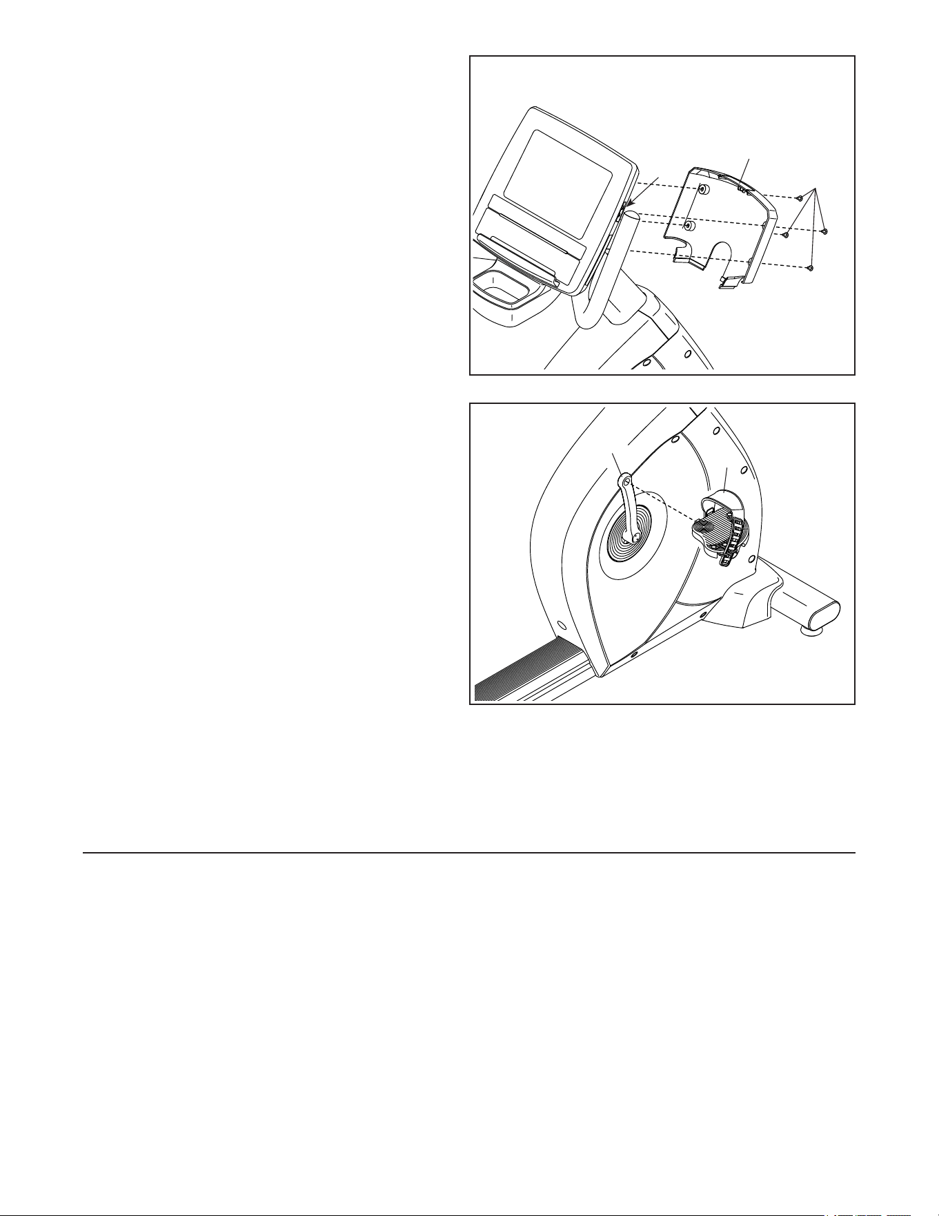
17. Identify the right Pedal (29). Using an adjustable
wrench, firmly tighten the right Pedal clock-
wise into the Right Crank Arm (16).
Firmly tighten the left Pedal (not shown)
counterclockwise into the Left Crank Arm
(not shown). IMPORTANT: You must turn the
left Pedal counterclockwise to attach it.
16. Tip: Avoid pinching the wires. Attach the
Handlebar Cover (46) to the Handlebar (47)
with four M5 x 10mm Screws (89); start all the
Screws, and then tighten them.
46
89
47
Avoid pinching
the wires
29
16
HOW TO UPGRADE THE CONSOLE
Your console has been preconfigured to operate with an optional digital TV.
To learn about the features of the basic console, see page 16. To learn about the features of the digital
TV, see the user’s manual included with the digital TV. The basic console has no television capabilities.
To upgrade your console to include a digital TV whenever you choose, please see the back cover of this manual.
15
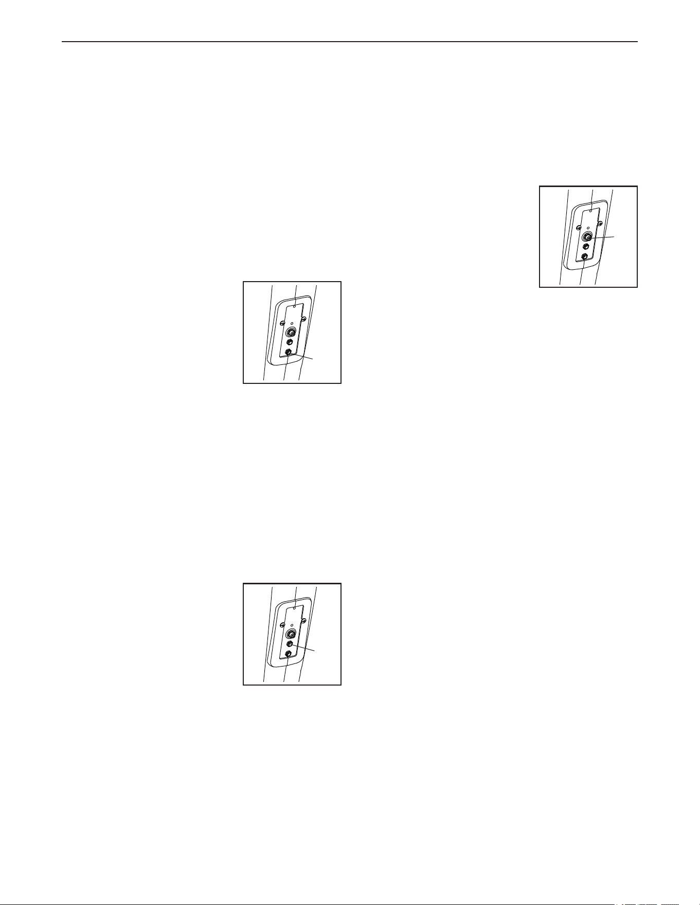
HOW TO PLUG IN THE INCLUDED POWER
ADAPTER
The exercise bike can be used with or without the
included power adapter. When the exercise bike is
used without the power adapter, power will be supplied
by an internal generator.
IMPORTANT: If the exercise bike has been exposed
to cold temperatures, allow it to warm to room
temperature before you plug in the power adapter.
If you do not do this, you may damage the console
displays or other electronic components.
Plug the power adapter into the
lower power receptacle (A) on
the frame of the exercise bike.
Then, plug the power adapter
into an appropriate outlet that
is properly installed in accor-
dance with all local codes and
ordinances.
HOW TO PLUG IN THE DIGITAL TV POWER
ADAPTER
If the exercise bike has an optional digital TV, the
power adapter included with the digital TV must be
used for the digital TV to operate.
IMPORTANT: If the exercise bike has been exposed
to cold temperatures, allow it to warm to room
temperature before you plug in the power adapter.
If you do not do this, you may damage the console
displays or other electronic components.
Plug the power adapter for
the optional digital TV into the
upper digital TV power recep-
tacle (B) on the frame of the
exercise bike. Then, plug the
power adapter into an appro-
priate outlet that is properly
installed in accordance with all
local codes and ordinances.
HOW TO CONNECT A COAXIAL CABLE TO THE
EXERCISE BIKE
If the exercise bike has an optional digital TV, a
coaxial cable must be connected to the exercise bike
for cable or over-the-air TV stations to be viewed.
Locate the coaxial cable
terminal (C) on the frame of
the exercise bike. Connect the
coaxial cable to the coaxial
cable terminal. Route the
coaxial cable so that it will not
be pinched or crushed by the
exercise bike.
A satellite receiver, VCR, or DVD player can also be
connected to the exercise bike. Connect a coaxial
cable from the coaxial output on your equipment (usu-
ally labeled TV OUT or RF OUT) to the coaxial cable
terminal (C) on the frame of the exercise bike.
Note: Audio/video equipment without coaxial outputs
may be able to be connected directly to the optional
digital TV; the optional digital TV has a variety of input
receptacles.
WARRANTY INFORMATION
The warranty for this product does not cover damage
or equipment failure caused by electric wiring not in
compliance with electrical codes or the specifications
in this manual, or failure to provide reasonable and
necessary maintenance as outlined in this manual.
Any failure or damage caused by unauthorized service;
misuse; accident; negligence; improper assembly or
installation; debris resulting from any destruction activi-
ties in the product’s environment; rust or corrosion as a
result of the product’s location; alterations or modifica-
tions without written authorization; or failure on your
part to use, operate, and maintain the product as set
forth in this manual will void the warranty.
All terms of the warranty are void if this prod-
uct is moved beyond the continental borders of
the United States of America (excluding Alaska,
Hawaii, and Canada) and are then subject to the
terms provided by that country’s local authorized
Freemotion Fitness, Inc. representative.
A
C
HOW TO USE THE EXERCISE BIKE
B
16
DK City
EBVM82018
VMEX82018
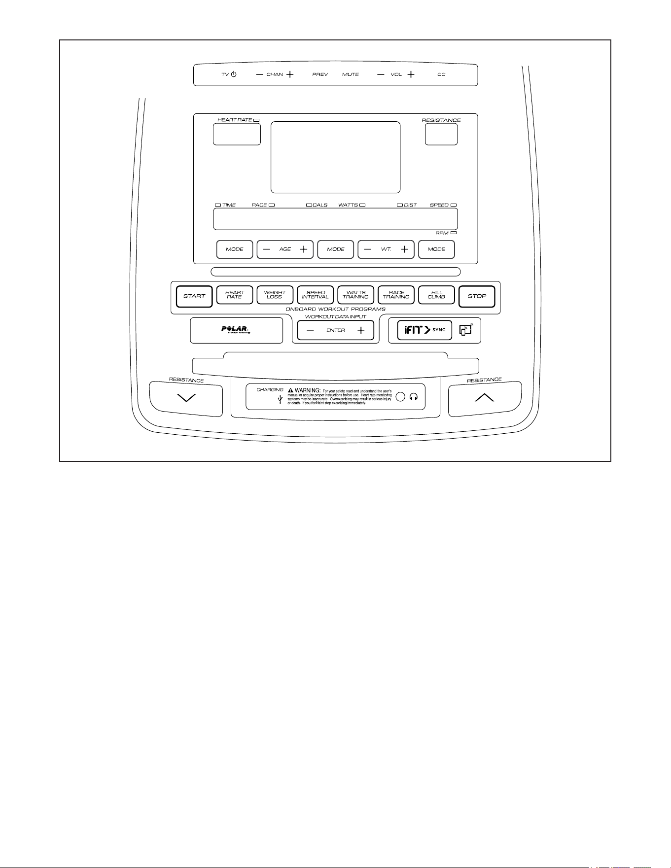
FEATURES OF THE CONSOLE
The console offers an impressive array of features
designed to make your workouts more effective and
enjoyable.
The console features a selection of onboard programs
that automatically control the resistance of the pedals
while guiding you through an effective exercise
session.
When you use the quick start mode, you can change
the resistance of the pedals with the touch of a button.
As you exercise, the console will display instant
exercise feedback. You can also measure your heart
rate using the handgrip heart rate monitor or a Polar
®
-
compatible chest heart rate monitor.
You can even connect your tablet to the console and
use the iFit
®
–Smart Cardio Equipment app to record
and track your workout information.
You can also use the charging port on the console
to charge your USB-compatible device while you
exercise.
To activate the console, see page 17. To turn off
the console, see page 17. To use the charging
port, see page 17.
To use the quick start mode, see page 18. To use
an onboard program, see page 20. To connect
your tablet to the console, see page 22. To
change console settings, see page 22.
Note: If there is a sheet of plastic on the display,
remove the plastic.
Note: The console can display speed and distance
in either miles and miles per hour or kilometers and
kilometers per hour. To find which unit of measure-
ment is selected, see HOW TO CHANGE CONSOLE
SETTINGS on page 22.
CONSOLE
DIAGRAM

17
HOW TO ACTIVATE THE CONSOLE
If the exercise bike has a basic console, it can be
used with or without the power adapter.
To use the exercise bike without the power adapter,
simply begin pedaling. The displays and indicators will
light and the words SELECT WORKOUT OR PRESS
START TO BEGIN will scroll across the message
banner.
While you pedal, power will be supplied by an internal
generator; remember to continue pedaling while you
use the exercise bike.
If the exercise bike has an optional digital TV,
the power adapter must be used for the digital TV to
be operated. See HOW PLUG IN THE DIGITAL TV
POWER ADAPTER on page 15.
When the power adapter is plugged in, the displays
and indicators will light and the words SELECT
WORKOUT OR PRESS START TO BEGIN will scroll
across the message banner.
HOW TO TURN OFF THE CONSOLE
If the pedals are not moved and no buttons are
pressed for a short while, the console will turn off
automatically.
If the exercise bike is being used with the power
adapter, unplug the power adapter when you are fin-
ished exercising. IMPORTANT: If you do not do this,
the electrical components on the exercise bike may
wear prematurely.
HOW TO USE THE CHARGING PORT
The console features a charging port that you can use
to charge USB-compatible devices, such as tablets
and smartphones, while you exercise.
To use the charging port, plug a USB charging cable
(not included) into the charging port on the front of the
console and into the receptacle on your device; make
sure that the USB charging cable is fully plugged
in. Note: The charging port cannot be used to view
or transfer data or to play music through the console
sound system.

18
HOW TO USE THE QUICK START MODE
1. Turn on the console.
See HOW TO ACTIVATE THE CONSOLE on
page 17.
2. Select the quick start mode.
To select the quick start mode, press the Start
button.
3. Change the resistance of the pedals as desired.
As you pedal, you can change the resistance of
the pedals. To change the resistance, press the
Resistance increase and decrease buttons on the
console or on the handlebars.
Note: After you press a button, it will take a
moment for the pedals to reach the selected
resistance level.
4. Follow your progress.
The displays can show the following workout
information:
Matrix—This display will show a profile of the
resistance levels of the workout or program.
Message Banner—This display will show a variety
of workout information and scrolling text messages.
Heart Rate—This display will show your heart rate
when you use the handgrip heart rate monitor or
a Polar-compatible chest heart rate monitor (see
step 5).
Resistance—This display will show the resistance
level of the pedals.
Time/Pace—This display will show the workout
time and your pedaling pace in minutes per mile
or minutes per kilometer in a repeating cycle (scan
mode).
To select either the time display or the pace display
for continuous display (priority mode), press the left
Mode button repeatedly until a solid light appears
next to the desired display. To return to the scan
mode, press the left Mode button until a flashing
light appears next to the displays in a repeating
cycle.
When the quick start mode is selected, the time
display will show the elapsed time. When a pro-
gram is selected, the time display will show the
time remaining in the program.
Note: The console can display distance in either
miles or kilometers. To find which unit of mea-
surement is selected, see HOW TO CHANGE
CONSOLE SETTINGS on page 22.
Cals/Watts—This display will show the approxi-
mate number of calories you have burned and your
power output in watts in a repeating cycle (scan
mode).
To select either the calories display or the watts
display for continuous display (priority mode), press
the center Mode button repeatedly until a solid light
appears next to the desired display. To return to
the scan mode, press the center Mode button until
a flashing light appears next to the displays in a
repeating cycle.
Dist/Speed/RPM—This display will show the
distance that you have pedaled in miles or kilome-
ters, your pedaling speed in miles or kilometers per
hour, and your pedaling speed in revolutions per
minute (RPM) in a repeating cycle (scan mode).
To select the distance, speed, or RPM display for
continuous display (priority mode), press the right
Mode button repeatedly until a solid light appears
next to the desired display. To return to the scan
mode, press the right Mode button until a flashing
light appears next to the displays in a repeating
cycle.
Note: The console can display speed in either
miles per hour or kilometers per hour. To find which
unit of measurement is selected, see HOW TO
CHANGE CONSOLE SETTINGS on page 22.
19
5. Measure your heart rate if desired.
You can use the handgrip heart rate monitor or you
can wear a Polar-compatible chest heart rate moni-
tor (not included) to measure your heart rate.
IMPORTANT: If you use both heart rate
monitors at the same time, the console will not
display your heart rate accurately.
To use the handgrip heart rate monitor, follow the
instructions below.
If there are
sheets of
plastic on
the metal
contacts (A)
on the hand-
grip heart
rate moni-
tor, remove
the plastic.
To measure
your heart
rate, hold the
handgrip heart rate monitor with your palms resting
against the contacts on the upper body arms or the
contacts on the handlebars. Avoid moving your
hands or gripping the contacts tightly.
When your pulse is detected, your heart rate will
be shown in the display. For the most accurate
heart rate reading, hold the contacts for at least 15
seconds.
If the display does not show your heart rate, make
sure that your hands are positioned as described.
Be careful not to move your hands excessively or
to squeeze the contacts tightly. For optimal perfor-
mance, clean the contacts using a soft cloth; never
use alcohol, abrasives, or chemicals to clean
the contacts.
6. Pause the workout if desired.
To pause the workout, press the Stop button.
Note: If the pedals are not moved and no buttons
are pressed for a short while, the console will exit
the quick start mode or the program.
To resume the workout, press the Start button.
7. End the workout and view the workout
summary.
When you are finished exercising, press the Stop
button.
A workout summary will appear in the message
banner.
8. Exit the workout summary.
To exit the workout summary, press the Stop button
twice.
Note: After a short while, the console will exit the
workout summary automatically.
9. Turn off the console.
See HOW TO TURN OFF THE CONSOLE on
page 17.
A
A

20
HOW TO USE AN ONBOARD PROGRAM
1. Turn on the console.
See HOW TO ACTIVATE THE CONSOLE on
page 17.
2. Select an onboard program.
To select an onboard program, press the Heart
Rate, Weight Loss, Speed Interval, Watts Training,
Race Training, or Hill Climb button repeatedly until
the desired program appears in the displays.
The message banner will show the name of the
program and other details about the program. The
matrix will show the profile of the program.
3. Enter your weight.
To enter your weight, press the Weight increase
and decrease buttons.
4. Enter your age.
To enter your age, press the Age increase and
decrease buttons.
5. Begin exercising.
Press the Start button and begin pedaling to begin
the program.
Heart Rate Program—Each heart rate program is
divided into segments. A target heart rate is pro-
grammed for each segment. During the program,
the profile in the matrix will show your progress.
The flashing segment of the profile represents the
current segment of the program. The height of the
flashing segment indicates the resistance level for
the current segment.
During the program, the console will regularly
compare your actual heart rate with the target heart
rate. To keep your actual heart rate near the target
heart rate, the console will automatically adjust
the resistance of the pedals and prompt you to
increase or decrease your pedaling speed. Keep
your pedaling speed near the target speed
shown in the message banner.
Note: The target heart rates are percentages of
your maximum heart rate. Your maximum heart
rate is estimated by subtracting your age from
220. For example, if you are 30 years old, your
estimated maximum heart rate is 190 beats per
minute (220 – 30 = 190). Therefore, if you are 30
years old, a target heart rate setting of 60 percent
is equal to 114 beats per minute (60 percent of
190 is 114). To determine a target heart rate that is
suitable for you, consult your physician or a physi-
cian-recommended source.
For the most accurate heart rate readings, it is
recommended that you wear a Polar-compatible
chest heart rate monitor while using the heart rate
program. You can also hold the handgrip heart rate
monitor during the heart rate program (see step 5
on page 19).
IMPORTANT: The target heart rate is intended
only to provide motivation. Make sure to exer-
cise at an intensity level that is comfortable for
you.
The program will continue in this way until the last
segment ends.
Weight Loss, Speed Interval, and Hill Climb
Programs—Each program is divided into seg-
ments. One resistance level and one target speed
is programmed for each segment. Note: The
same resistance level and/or target speed may be
programmed for consecutive segments.
During the program, the profile in the matrix will
show your progress. The flashing segment of the
profile represents the current segment of the pro-
gram. The height of the flashing segment indicates
the resistance level for the current segment.
If the resistance level is too high or too low, you
can manually override the resistance level by
pressing the Resistance increase and decrease
buttons.
The console will prompt you to increase or
decrease your pedaling speed. Keep your pedal-
ing speed near the target speed shown in the
message banner.

21
IMPORTANT: The target speed is intended only
to provide motivation. Make sure to exercise at
an intensity level that is comfortable for you.
If the resistance level is too high or too low, you
can manually override the resistance level by
pressing the Resistance increase and decrease
buttons. IMPORTANT: The resistance level
will automatically adjust at the end of each
segment.
The program will continue in this way until the last
segment ends.
Watts Training Program—Each program is
divided into segments. A watts target is pro-
grammed for each segment. During the program,
the profile in the matrix will show your progress.
The flashing segment of the profile represents the
current segment of the program. The height of the
flashing segment indicates the resistance level for
the current segment.
To keep your actual watts output near the watts
target, the console will automatically adjust
the resistance of the pedals and prompt you
to increase or decrease your pedaling speed.
Increase or decrease your pedaling speed to
keep your actual watts output near the watts
target shown in the message banner.
IMPORTANT: The watts target is intended only
to provide motivation. Make sure to exercise at
an intensity level that is comfortable for you.
If the resistance level is too high or too low, you
can manually override the resistance level by
pressing the Resistance increase and decrease
buttons. IMPORTANT: The resistance level
will automatically adjust at the end of each
segment.
The program will continue in this way until the last
segment ends.
Race Training Program—Each program is divided
into segments. During the program, the profile
in the matrix will show your progress. The flash-
ing segment of the profile represents the current
segment of the program. The height of the flashing
segment indicates the resistance level for the cur-
rent segment.
As you exercise, change the resistance of the
pedals as desired (see step 3 on page 18). The
display will count down the distance you have
pedaled.
The program will continue in this way until the last
segment ends.
6. Follow your progress.
See step 4 on page 18.
7. Measure your heart rate if desired.
See step 5 on page 19.
8. Pause the program if desired.
See step 6 on page 19.
9. End the program and view the workout
summary.
See step 7 on page 19.
10. Exit the workout summary.
See step 8 on page 19.
11. Turn off the console.
See HOW TO TURN OFF THE CONSOLE on
page 17.

22
HOW TO CONNECT YOUR TABLET TO THE
CONSOLE
The console supports Bluetooth connections to tablets
via the iFit–Smart Cardio Equipment app. Note: Other
Bluetooth connections are not supported.
1. Download and install the iFit–Smart Cardio
Equipment app on your tablet.
On your iOS
®
or Android™ tablet, open the App
Store℠ or the Google Play™ store, search for the
free iFit–Smart Cardio Equipment app, and then
install the app on your tablet. Make sure that the
Bluetooth option is enabled on your tablet.
Then, open the iFit–Smart Cardio Equipment app
and follow the instructions to set up an iFit account
and customize settings.
2. Connect your tablet to the console.
Press the iFit Sync button on the console. Then,
follow the instructions in the iFit–Smart Cardio
Equipment app to connect your tablet to the
console.
3. Record and track your workout information.
Follow the instructions in the iFit–Smart Cardio
Equipment app to record and track your workout
information.
4. Disconnect your tablet from the console if
desired.
To disconnect your tablet from the console, first
select the disconnect option in the iFit–Smart
Cardio Equipment app. Then, press and hold the
iFit Sync button on the console.
HOW TO CHANGE CONSOLE SETTINGS
1. Turn on the console.
See HOW TO ACTIVATE THE CONSOLE on
page 17.
2. Select the settings mode.
To select the settings mode, press and hold the left
Mode button.
3. Navigate the settings mode.
While the settings mode is selected, the display
will show several optional screens. Press the Stop
button repeatedly to select the desired optional
screen.
The message banner will show instructions for
the selected screen. Make sure to follow the
instructions shown in the message banner.
4. Change settings as desired.
Units—The currently selected unit of measurement
will appear in the message banner. To change the
unit of measurement, press the center Mode but-
ton repeatedly. To view distance in miles, select
ENGLISH. To view distance in kilometers, select
METRIC.
Display Test—This option is intended to be used
by service technicians.
Button Test—This option is intended to be used
by service technicians to identify whether a certain
button is working correctly.
Software Version Number—The software version
number will appear in the message banner.
Total Time and Total Distance—The total number
of hours that the exercise bike has been used and
the total distance that the exercise bike has been
pedaled will appear in the message banner.
CSAFE Login—Press the center Mode button
repeatedly to enable or disable the CSAFE login
functionality.

23
Pause Timeout—The selected pause time will
appear in the message banner. When the console
is paused, it will exit the workout or program after
the entered number of seconds if the pedals do
not move and no buttons are pressed. To change
the pause timeout, press the Age increase and
decrease buttons.
Idle Timeout—The selected idle time will appear
in the message banner. When the console is idle,
it will turn off after the entered number of seconds
if the pedals do not move and no buttons are
pressed. To change the idle timeout, press the Age
increase and decrease buttons.
TV Setup—This option is used to set up an
optional digital TV (see HOW TO UPGRADE
the console on page 14). When this option
is selected, the buttons on the console are pro-
grammed to access various menus and options on
the optional digital TV as described below.
Center Mode button—Press this button to
select the digital TV setup menu.
Chan increase and decrease buttons—
Press these buttons to navigate up and down
in the digital TV menus.
Vol increase and decrease buttons—Press
these buttons to navigate right and left in the
digital TV menus.
Enter button/right Mode button—Press
these buttons to make a selection.
Left Mode button—Press this button to select
a TV source.
Start button—Press this button to select the
digit 0.
Heart Rate button—Press this button to select
the digit 1.
Weight Loss button—Press this button to
select the digit 2.
Speed Interval button—Press this button to
select the digit 3.
Watts Training button—Press this button to
select the digit 4.
Race Training button—Press this button to
select the digit 5.
Hill Climb button—Press this button to select
the digit 6.
Decrease button next to Enter button—Press
this button to select the digit 7.
Increase button next to Enter button—Press
this button to select the digit 8.
iFit Sync button—Press this button to select
the digit 9.
For more information, see the user’s manual
included with the optional digital TV.
Language—The selected language will appear
in the message banner. The console will dis-
play text messages in the selected language. To
select a language, press the center Mode button
repeatedly.
Bluetooth Low Energy—Press the center
Mode button repeatedly to enable or disable the
Bluetooth Low Energy functionality.
5. Exit the settings mode.
Press the Stop button to exit the settings mode.

24
COMPLIANCE INFORMATION
UNITED STATES
FCC Statement. This equipment has been tested and found to comply with the limits for a Class B digital device,
pursuant to Part 15 of the FCC Rules. These limits are designed to provide reasonable protection against harm-
ful interference in a residential installation. This equipment generates, uses, and can radiate radio frequency
energy and, if not installed and used in accordance with the instructions, may cause harmful interference to radio
communications. However, there is no guarantee that interference will not occur in a particular installation. If this
equipment does cause harmful interference to radio or television reception, which can be determined by turning
the equipment off and on, try to correct the interference by one or more of the following measures:
• Reorient or relocate the receiving antenna.
• Increase the separation between the equipment and the receiver.
• Connect the equipment into an outlet on a circuit different from that to which the receiver is connected.
• Consult the dealer or an experienced radio/TV technician for help.
FCC CAUTION: To assure continued compliance, use only shielded interface cables when connecting to
computer or peripheral devices. Changes or modifications not expressly approved by the party respon-
sible for compliance could void the user’s authority to operate this equipment.
CANADA
IC Statement. This Class B digital device complies with Canadian ICES-003. Operation is subject to the fol-
lowing two conditions: (1) This device may not cause harmful interference, and (2) this device must accept any
interference received, including interference that may cause undesired operation.

25
MAINTENANCE
Inspect and tighten all parts of the exercise bike
regularly. Replace any worn parts immediately.
To clean the exercise bike, use a damp cloth and a
small amount of mild soap. IMPORTANT: To avoid
damage to the console, keep liquids away from
the console and keep the console out of direct
sunlight.
CONSOLE TROUBLESHOOTING
If the console does not display your heart rate when
you hold the handgrip heart rate monitor, or if the dis-
played heart rate appears to be too high or too low, see
step 5 on page 19.
If a replacement power adapter is needed, call the
telephone number on the cover of this manual.
IMPORTANT: To avoid damaging the console, use
only a manufacturer-supplied regulated power
adapter.
CHARGING THE GENERATOR
See EXPLODED DRAWING A on page 29. For best
results, charge the internal Battery (2) that powers the
Generator (31) once per week. To charge the Battery,
plug the Power Adapter (130) into the receptacle on
the frame of the exercise bike.
MAINTENANCE AND TROUBLESHOOTING
26
EXERCISE GUIDELINES
These guidelines will help you to plan your exercise
program. For detailed exercise information, obtain a
reputable book or consult your physician. Remember,
proper nutrition and adequate rest are essential for
successful results.
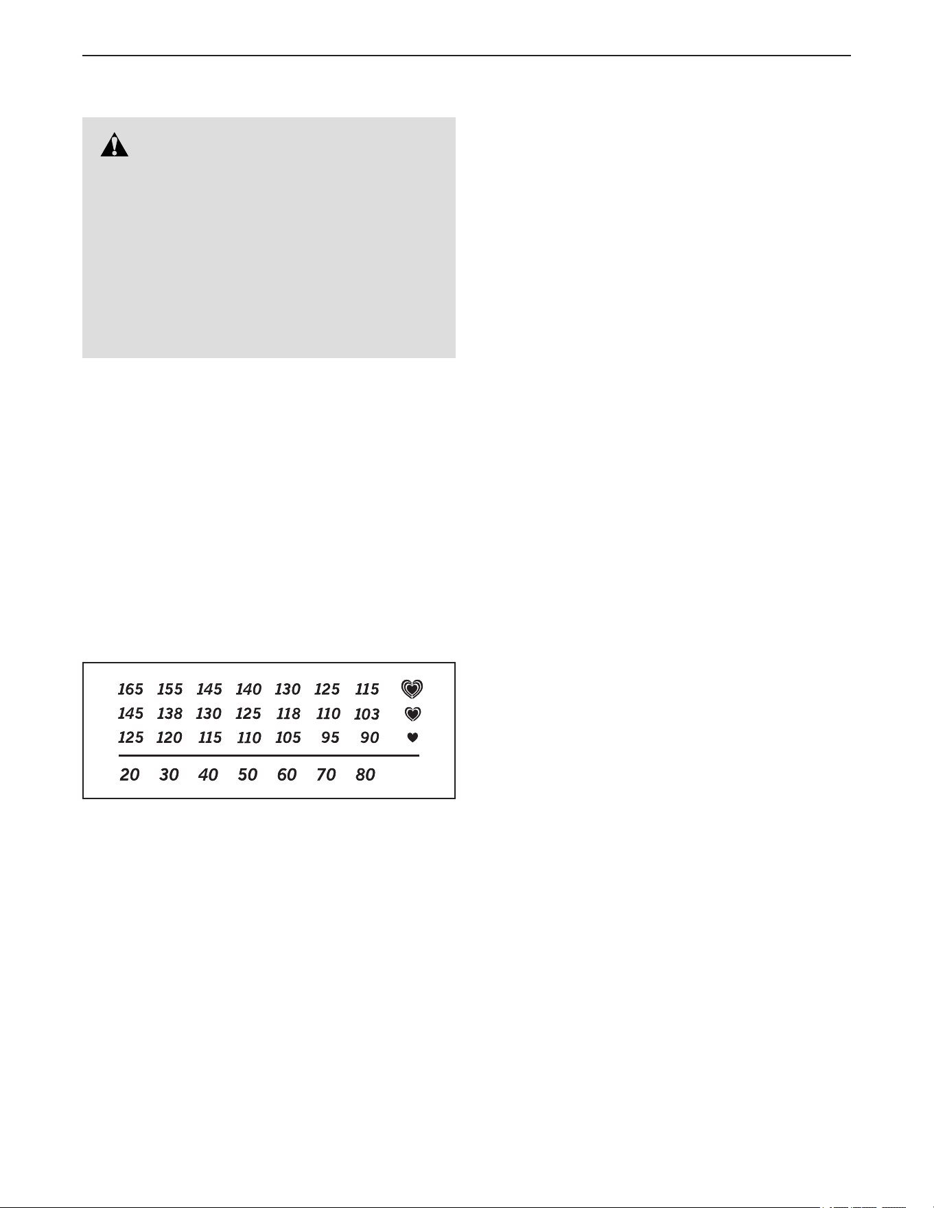
EXERCISE INTENSITY
Whether your goal is to burn fat or to strengthen your
cardiovascular system, exercising at the proper inten-
sity is the key to achieving results. You can use your
heart rate as a guide to find the proper intensity level.
The chart below shows recommended heart rates for
fat burning and aerobic exercise.
To find the proper intensity level, find your age at the
bottom of the chart (ages are rounded off to the near-
est ten years). The three numbers listed above your
age define your “training zone.” The lowest number is
the heart rate for fat burning, the middle number is the
heart rate for maximum fat burning, and the highest
number is the heart rate for aerobic exercise.
Burning Fat—To burn fat effectively, you must exer-
cise at a low intensity level for a sustained period of
time. During the first few minutes of exercise, your
body uses carbohydrate calories for energy. Only after
the first few minutes of exercise does your body begin
to use stored fat calories for energy. If your goal is to
burn fat, adjust the intensity of your exercise until your
heart rate is near the lowest number in your training
zone. For maximum fat burning, exercise with your
heart rate near the middle number in your training
zone.
Aerobic Exercise—If your goal is to strengthen your
cardiovascular system, you must perform aerobic
exercise, which is activity that requires large amounts
of oxygen for prolonged periods of time. For aerobic
exercise, adjust the intensity of your exercise until your
heart rate is near the highest number in your training
zone.
WORKOUT GUIDELINES
Warming Up—Start with 5 to 10 minutes of stretch-
ing and light exercise. A warm-up increases your body
temperature, heart rate, and circulation in preparation
for exercise.
Training Zone Exercise—Exercise for 20 to 30 min-
utes with your heart rate in your training zone. (During
the first few weeks of your exercise program, do not
keep your heart rate in your training zone for longer
than 20 minutes.) Breathe regularly and deeply as you
exercise ; never hold your breath.
Cooling Down—Finish with 5 to 10 minutes of stretch-
ing. Stretching increases the flexibility of your muscles
and helps to prevent post-exercise problems.
EXERCISE FREQUENCY
To maintain or improve your condition, complete
three workouts each week, with at least one day of
rest between workouts. After a few months of regular
exercise, you may complete up to five workouts each
week, if desired. Remember, the key to success is to
make exercise a regular and enjoyable part of your
everyday life.
WARNING: Before beginning this
or any exercise program, consult your physi-
cian. This is especially important for persons
over age 35 or persons with pre-existing
health problems.
The heart rate monitor is not a medical device.
Various factors may affect the accuracy of
heart rate readings. The heart rate monitor is
intended only as an exercise aid in determin-
ing heart rate trends in general.

27
1 1 Frame
2 1 Battery
3 1 Hook and Loop Fastener
4 1 Upright
5 1 Console
6 4 M8 Nut
7 1 Wear Cover
8 2 Idler Bearing
9 1 Small Accessory Tray
10 1 Rail
11 1 Seat Carriage
12 1 Seat
13 1 Backrest
14 1 Backrest Frame
15 1 Seat Handle
16 1 Right Crank Arm
17 1 Idler Spacer
18 1 Seat Frame
19 1 Front Shield Cap
20 1 Front Shield Cover
21 1 Left Front Shield
22 1 Right Front Shield
23 1 Left Rear Shield
24 1 Right Rear Shield
25 1 Left Crank Arm
26 4 Stabilizer Cap
27 1 Rear Shield Cover
28 4 Leveling Foot
29 1 Pedal/Strap Set
30 4 Rail Plate
31 1 Generator
32 1 Idler Bracket
33 1 Rail Cover
34 1 Eyebolt
35 1 Seat Frame Plate
36 3 M4 x 15mm Flat Head Screw
37 1 Rear Stabilizer
38 1 Crank
39 2 Backrest Spacer
40 1 Pulley
41 1 Control Board
42 1 Accessory Tray Cover
43 2 Long Grip
44 1 Wiring Plate
45 2 Grip Cap
46 1 Handlebar Cover
47 1 Handlebar
48 1 Idler Spring
49 1 20mm Snap Ring
50 1 Front Stabilizer
51 2 Receptacle Plug
52 1 Large Accessory Tray
53 2 Short Grip
54 1 Seat Handle Spring
55 1 Handle Bushing
56 1 Ground Wire
57 2 Wheel
58 2 Coupler
59 1 Drive Belt
60 2 Rail Plate
61 6 Clip Nut
62 2 Rear Rail Bumper
63 1 Wire Clamp
64 1 Seat Frame Cap
65 2 Control Grip
66 8 M8 x 15mm Truss Screw
67 8 M8 x 15mm Flat Head Screw
68 2 M8 x 25mm x 2mm Washer
69 2 Control Plate
70 2 Grip Plate
71 2 Control Switch
72 2 Keypad
73 1 Screw Cap
74 1 M6 x 15mm Hex Screw
75 2 M8 x 25mm Flange Screw
76 4 M8 x 15mm Screw
77 19 M8 Split Washer
78 21 M5 x 12mm Screw
79 1 Upper Main Wire
80 8 M8 x 16mm x 1mm Washer
81 7 M5 x 10mm Truss Screw
82 4 M6 x 12mm Truss Screw
83 2 M6 Nut
84 2 M8 x 40mm Bolt
85 8 M8 Locknut
86 4 M8 x 10mm Screw
87 4 M6 x 15mm Flange Screw
88 2 M5 x 30mm Screw
89 6 M5 x 10mm Screw
90 1 M4 x 10mm Wire Clip Screw
91 1 M6 x 19mm x 1.5mm Washer
92 4 M8 x 12mm x 1mm Washer
93 4 M8 x 20mm Screw
94 2 M4 x 25mm Screw
95 4 M6 x 35mm Screw
96 4 M6 Split Washer
97 4 M6 x 1mm Washer
98 1 M8 x 25mm Button Screw
99 1 Upper Pulse Wire
100 1 Upper TV Coaxial Cable
Key No. Qty. Description Key No. Qty. Description
PART LIST
Model No. VMEX82018.0 R0619B

28
101 11 M4 x 16mm Self-tapping Screw
102 8 M5 x 16mm Screw
103 4 M8 x 20mm Hex Screw
104 4 Roller Sleeve
105 1 M8 x 40mm Screw
106 6 Roller
107 2 Roller Axle
108 3 M12 Locknut
109 4 M8 x 35mm Hex Bolt
110 12 M8 x 16mm x 1.5mm Washer
111 4 M3 x 25mm Screw
112 2 M2 x 5mm Screw
113 2 M4 x 8mm Flat Head Screw
114 2 M4 Washer
115 1 Upper Power Wire
116 1 Brake Axle
117 1 Brake Spacer
118 1 USB Host Board
119 4 M8 x 2mm Washer
120 1 M8 x 20mm x 1.5mm Washer
121 1 Lower TV Coaxial Cable
122 1 Lower Power Wire
123 1 Lower Main Wire
124 1 Lower Pulse Wire
125 4 M8 x 12mm Seat Screw
126 1 M8 x 15mm Button Screw
127 1 Brake Block
128 4 M6 x 15mm Screw
129 1 C-SAFE Board
130 1 Power Adapter/Wire
131 1 Handlebar Cover Cap
132 2 Crank Bearing
133 1 Crank Spacer
134 1 Bearing Spacer
135 1 M4 x 10mm Screw
136 1 M5 x 12mm x 1mm Washer
137 1 M4 x 8mm Screw
138 4 M8 x 25mm Cap Screw
139 1 USB/Earphone Board
140 1 Ground Bar
141 1 Console Shelf
142 2 M8 x 25mm x 1.5mm Washer
143 2 M8 x 16mm x 2mm Washer
144 1 Tablet Shelf
145 2 M8 x 40mm Cap Screw
146 6 C-SAFE/USB Host Board Screw
147 1 Pulse board
148 1 M8 Bright Split Washer
149 4 Pulse Board Screw
150 2 USB/Earphone Screw
151 1 20" Board Wire
152 1 In 12" Board Wire
153 1 Out 12" Board Wire
154 2 Crank Cap
155 2 M8 Arc Washer
156 1 Crank Nut
157 2 Front Rail Bumper
* – User’s Manual
* – Assembly Tool
Key No. Qty. Description Key No. Qty. Description
Note: Specifications are subject to change without notice. For information about ordering replacement parts, see
the back cover of this manual. *These parts are not illustrated.
29
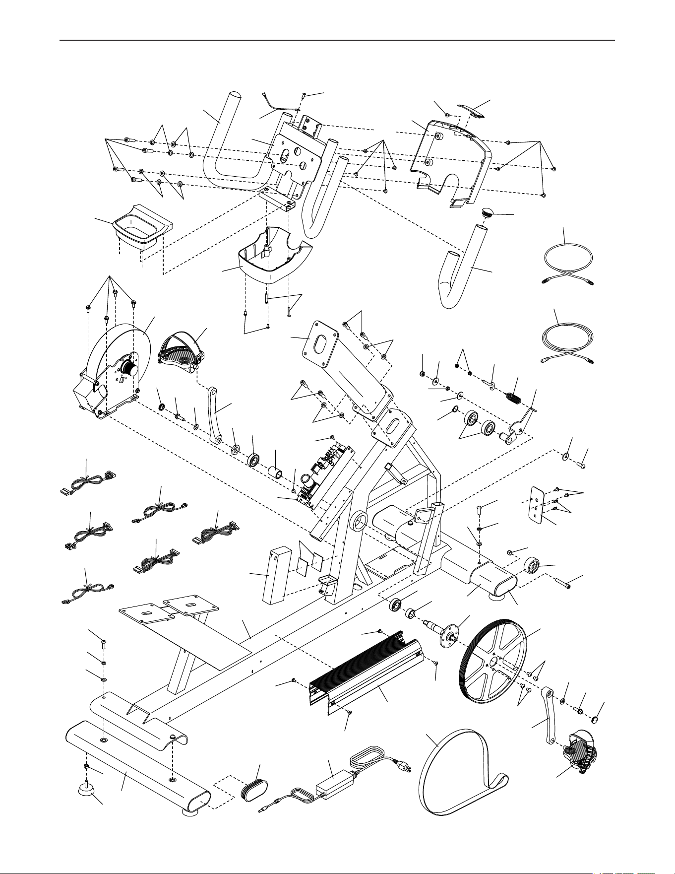
EXPLODED DRAWING A
Model No. VMEX82018.0 R0619B
81
81
83
1
3
6
8
2
4
7
9
26
28
32
31
34
38
40
41
43
43
46
131
135
56
81
48
45
42
44
51
47
49
59
57
26
81
89
86
86
130
88
85
138
110
138
85
68
17
142
98
68
82
82
37
82
82
50
76
77
77
80
80
84
87
89
78
92
92
93
93
154
156
132
134
132
133
155
154
155
79
99
123
124
115
122
121
100
77
77
110
29
29
16
25
75
75
30
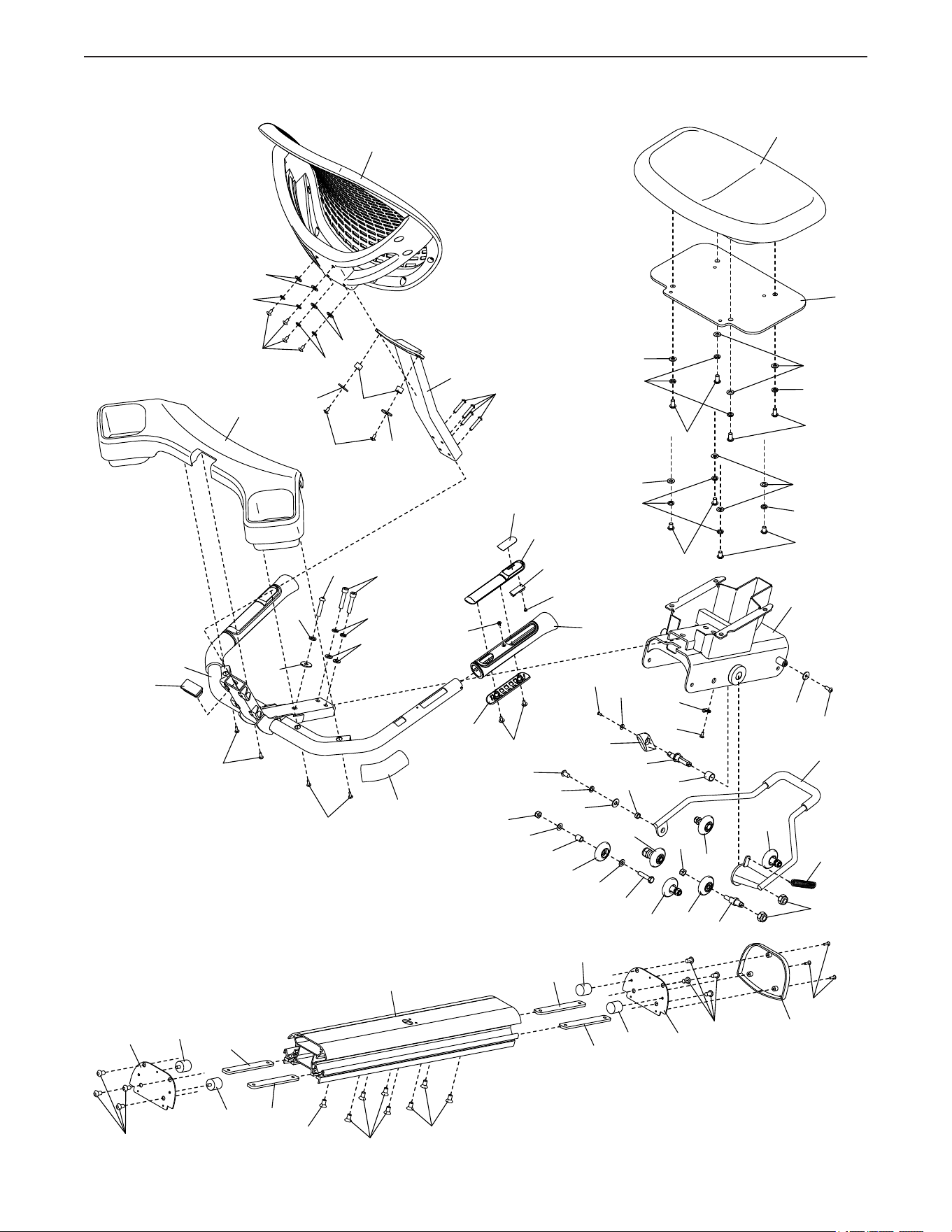
EXPLODED DRAWING B
Model No. VMEX82018.0 R0619B
105
145
143
137
127
136
10
12
11
18
15
54
53
60
63
91
74
157
157
62
64
90
103
103
77
77
77
80
80
119
119
62
60
148
77
101
101
66
30
30
67
67
67
30
30
66
33
36
106
106
107
108
106
106
85
125
125
35
142
14
95
94
39
114
114
52
65
69
70
72
71
116
117
126
77
120
106
55
85
110
104
106
110
109
112
111
113
13
128
96
96
97
97
77
31
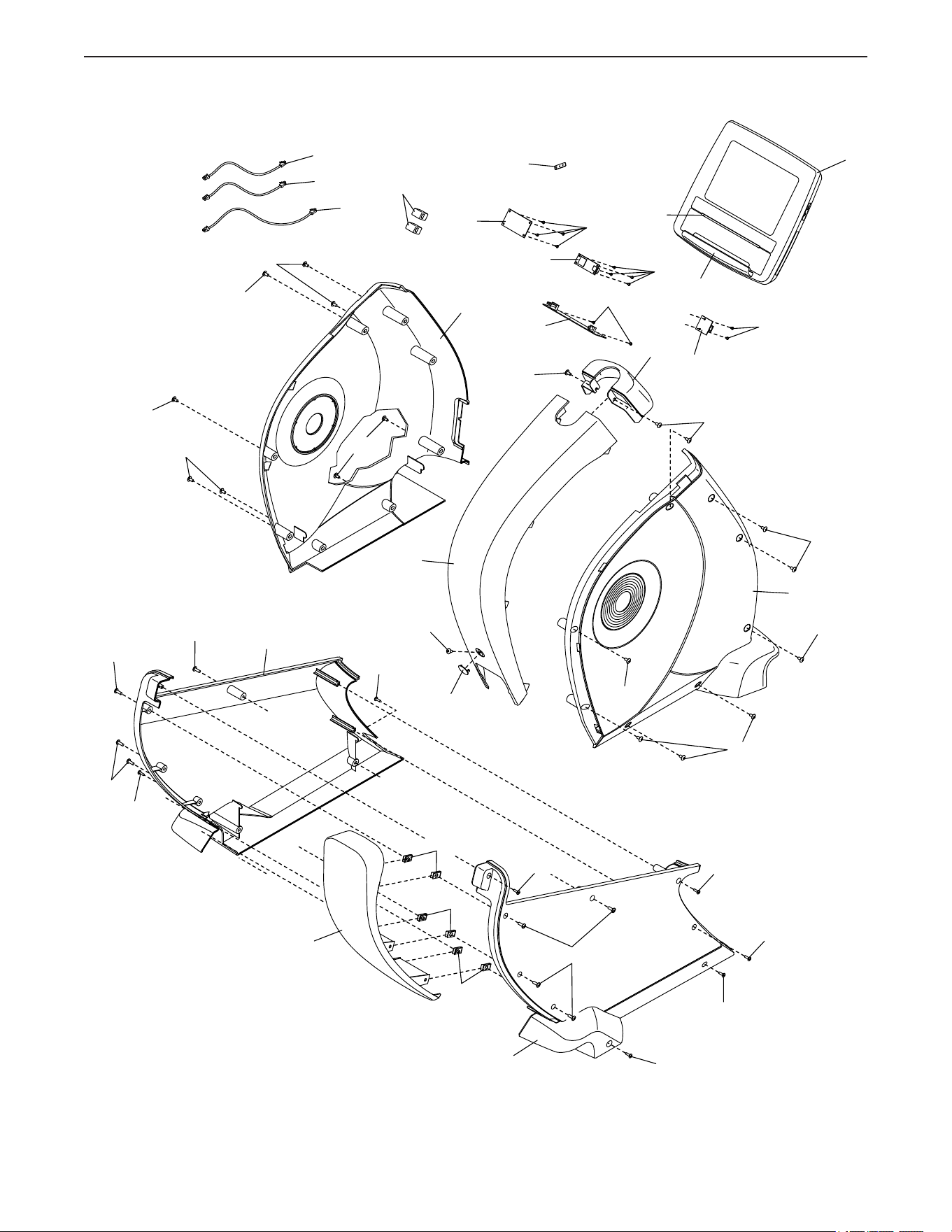
EXPLODED DRAWING C
Model No. VMEX82018.0 R0619B
19
20
21
23
22
24
27
78
78
78
78
78
78
78
78
78
78
78
78
73
101
101
102
102
5
129
139
140
141
144
151
152
153
149
146
146
150
147
118
58
101
101
102
102
101
101
101
61
61
61

Part No. 409266 R0619B Printed in Taiwan © 2019 ICON Health & Fitness, Inc.
HOW TO CONTACT CUSTOMER CARE
If you have questions after reading this manual, or if parts are damaged or missing, please contact Customer
Care at one of the phone numbers or addresses listed below. Please note the model number, serial number,
and name of the product (see the front cover of this manual) before contacting Customer Care. If you are
ordering replacement parts, please also note the key number and description of each part (see the PART
LIST and the EXPLODED DRAWING near the end of this manual).
In the United States
Call: 1-800-201-2109, Mon.–Fri. 6 a.m.–6 p.m. MT
Email: [email protected]
Write:
Freemotion Fitness
1500 South 1000 West
Logan, UT 84321-9813
United States
Outside the United States
Call: 001-800-527-5417 or 001-435-786-3521,
Mon.–Fri. 6 a.m.–3 p.m. USA Mountain Time
Email: [email protected]
This product is warranted for use in non-dues-paying
institutional settings to include hotels, apartment fitness
centers, corporate fitness centers, fire/police stations,
and hospital/physical therapy settings. This product is
not warranted for use in large, heavy-use settings such
as health clubs, colleges/universities, community cen-
ters, or military installations; use of this product in such
settings or use of this product for more than 6 hours per
day will void this warranty.
WARRANTY PERIODS AND COVERAGE
Freemotion Fitness warrants this product to be free from
defects in workmanship and material under normal use and
service conditions. Parts and labor are warranted for one (1)
year, unless otherwise specified on the invoice.
The warranty period commences on the invoice date of
purchase. Any parts repaired or replaced during this warranty
period will be warranted for the remainder of the original war-
ranty period.
CONDITIONS AND LIMITATIONS
The following will void the warranty on this product:
1. This warranty applies only to the original owner and is
non-transferable.
2. The labor warranty applies only to products sold in the US
and Canada. Contact your authorized Freemotion Fitness
dealer for details on labor coverage in your country.
3. Any misuse, abuse, or improper service.
4. Users who weight more than the maximum user weight
listed in this manual.
5. Damage caused by moving the product or improper stor-
age including moving or storing the product on its side.
6. Use or storage of the product outdoors or in high-humidity
environments including spa and pool areas.
7. Damage caused by improper wiring or insufficient electri-
cal current. Note: This product may not have wiring.
This warranty shall not apply to the following:
1. Cosmetic items including grips, decals, and labels.
2. Pick-up and delivery or freight charges involved with a
repair.
3. Any problem as a result of improper assembly or delivery.
WHAT TO DO IF SERVICE IS REQUIRED
Freemotion Fitness warranty service may be obtained by
contacting the authorized dealer from which you purchased
this product. Make sure to retain your original invoice and
serial number information. If this product experiences a fail-
ure under the warranty terms set forth, Freemotion Fitness
shall provide at their option either repair, replacement, or
refund of the purchase price. Freemotion Fitness compen-
sates service providers for warranty trips within their service
area. You may be charged additionally for service calls
beyond this service area.
Freemotion Fitness is not responsible or liable for indirect,
special, or consequential damages arising out of or in con-
nection with the use or performance of the product; damages
with respect to any economic loss, loss of property, loss
of revenues or profits, loss of enjoyment or use, or cost of
removal or installation; or other consequential damages.
Some regions do not allow the exclusion or limitation of con-
sequential damages. Accordingly, the above limitation may
not apply to you. This warranty gives you specific rights, and
you may have other rights that vary from region to region.
TO CONTACT FREEMOTION FITNESS
See HOW TO CONTACT CUSTOMER CARE above.
LIMITED WARRANTY