Model: RC-PRO
IMPORTANT
Please read this manual before assembling and using.
Retain owner’s manual for using instructions.
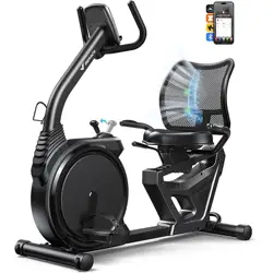
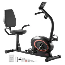
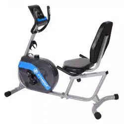
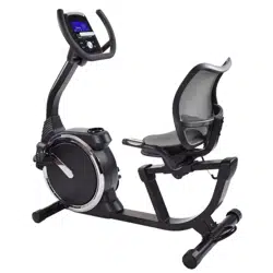
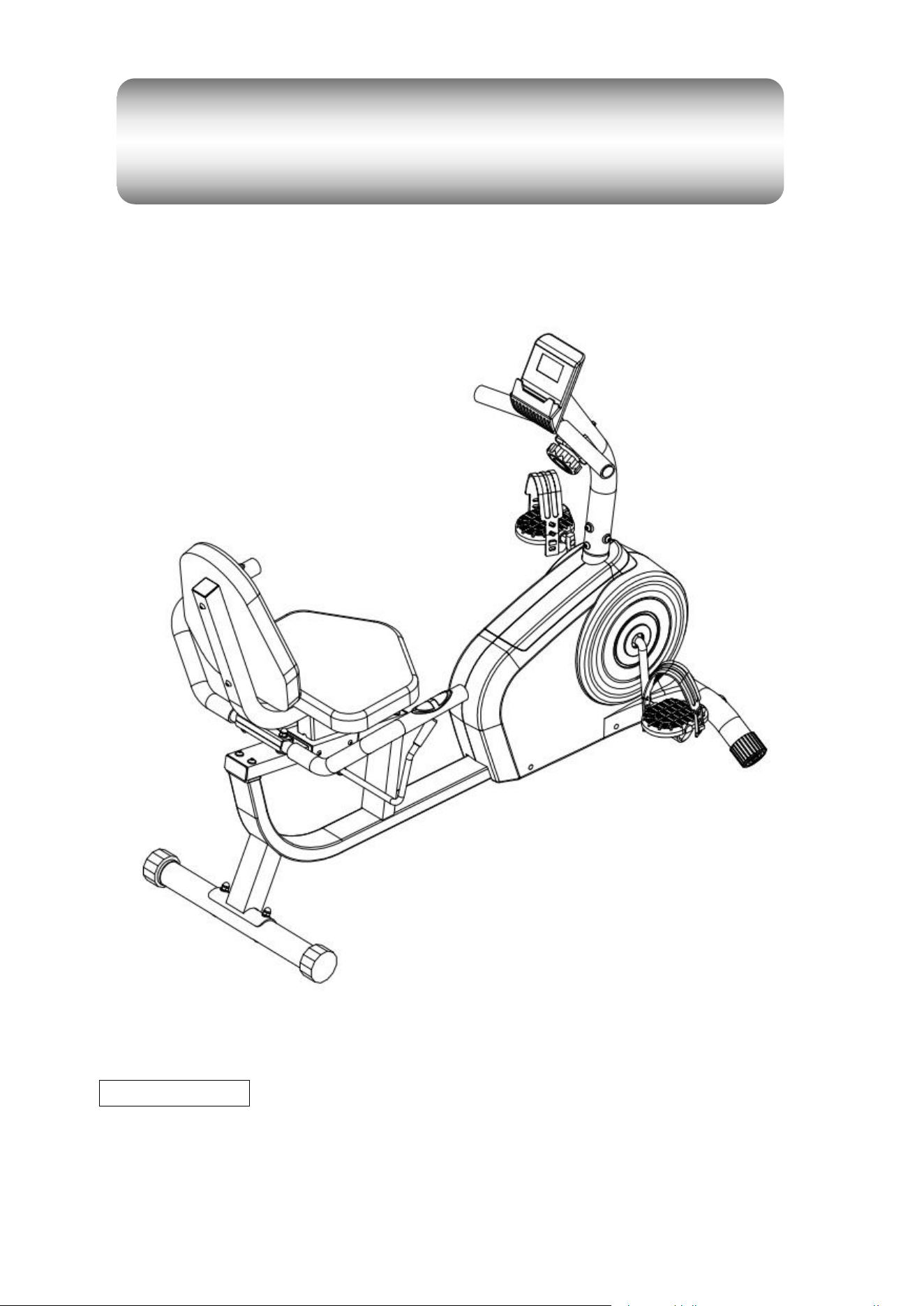
YOSUDA Recumbent Exercise Bike
Assembly Manual

CATALOGUE
CUSTOMER SERVICE........................................................................................ 2
ASSEMBLY VIDEO ...............................................................................................2
Step1 .................................................................
...................................................
IMPORTANT SAFETY INFORMATION ............................................................ 3
EXPLODED DRAWING............................................................................
............4
HARDWARE PACKAGE...................................................................................... 5
PARTS LIST........................................................................................................... 6
ASSEMBLY INSTRUCTIONS ............................................................................. 7
7
Step2 ....................................................................................................................8
Step3 ....................................................................................................................9
Step4 ...................................................................................................
..............
10
Step5 ................................................................................................................. 10
Step6 ................................................................................................................. 11
Step7 ................................................................................................................. 12
Step8 ...................
.............................................................................................. 13
ADJUSTING THE SADDLE ...............................................................................14
ADJUSTING THE RESISTANCE ..................................................................... 15
ADJUSTING THE HEIGHT AND BALANCE ..................................................15
HOW TO MOVE THE BIKE ................
............................................................... 16
1

2
CUSTOMER SERVICE
If you have any needs, please feel free to contact our customer service:
① Contact us via email: yosudaspo[email protected]om
② Contact us via Amazon:
>Login your Amazon account
>choose “Your orders”
>find the order ID
>click “Contact seller”
We are very grateful that you can actively keep in touch with us, and we will definitely
do our best to provide satisfactory service for everyone!
ASSEMBLING VIDEO
① From YouTube:
Search “YOSUDA Recumbent exercise bike RC-Pro Assembly”on YouTube.
② From the Amazon:
>open the Amazon shopping application on your phone.
>scan the
transparency barcode
on the packaging box.

3
IMPORTANT SAFETY INFORMATION
We thank you for choosing our p ro duct. To ensure your safety and health, ple ase use this
equipment correctly. It is important to read this entire manual before assembling and using the
equipment. Safe and e ffective use can only be assured if t he equipment is assembled, maintained,
and used properly. It is your responsibility to ensure that all users of the equipment are informed of
all warnings and precautions.
1. Before starting any exercise
program you should consult your physician to determine if you
have any medical or physical conditions that could pu t your health and safety at risk or
prevent you from using the equipmen t properly. Your physician’s advice is essential if you are
taking any medication that ma y affect your heart rate, blood pressure, or chole sterol level.
2. Be aware of your body’s signals. Incorrect or excessive exercise can damage your health.
Stop exercising if you experience any of the fo
llowing symptoms: pain, tightness in your chest,
irregular heartbeat, sh ortne ss of breath, lightheadedness, dizziness, or feelings of nausea. If
you do experience any of these conditions, you should consult your physician before
continuing with your exercise program.
3. Keep children and p ets away from the equipment. The equipment is designed for adult use
only.
4. Use the equipment on a solid, flat level surface with a protective cover for your floor or carpet.
To ensu
re safety, the equipmen t should have at least 4 feet o f free space all around it.
5. Ensure that all nuts and b olts are securely tightened before using the equipment. The safety
of the equipment can only be maintained if it is regularly examined for damage and/or wear
and tear.
6. It is recommended t hat you lubricate all moving parts on a monthly basis.
7. Always use the equipment as in dicated. If you find any defective components while
assembling or checking the equipment, or if
you hear any unusual noises coming from t he
equipment during exercise, stop using the equipment immediately and don’t use t he
equipment until the problem has been rectified.
8. Wear suitable clothing while usin g the equipment. Avoid wearing loose clothing that m ay
become entangled in the equipmen t.
9. Do not place fingers or objects into the m oving parts of the equipment.
10.The maximu m weight capacity of this unit is 350LB.
11. This equipment is not suitable for therapeu
tic use.
12.Move with caution when lifting and moving the equipment. Always use proper lifting te chnique
and seek assistance if necessary.
13.Your product is intended for use in cool, dry conditions.You sho uld avoid storage in extreme
cold, hot, or damp areas as this may lead to corrosion and other related problems.
14.This equipment is designed for indoor use only! It is not in tended for comm ercial use!
WARNING: This product can expose you to one or more ch em icals known to the
State of California to cause ca ncer and birth defects or reproductive harm. For more
information go to www.P65Warnings.ca.gov.
4
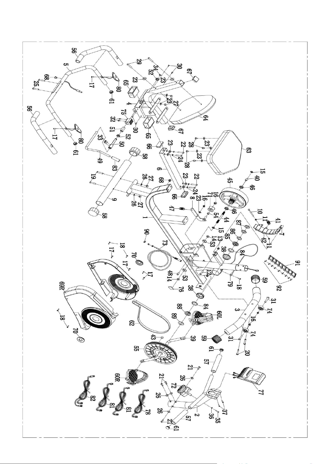
EXPLODED DRAWING
5
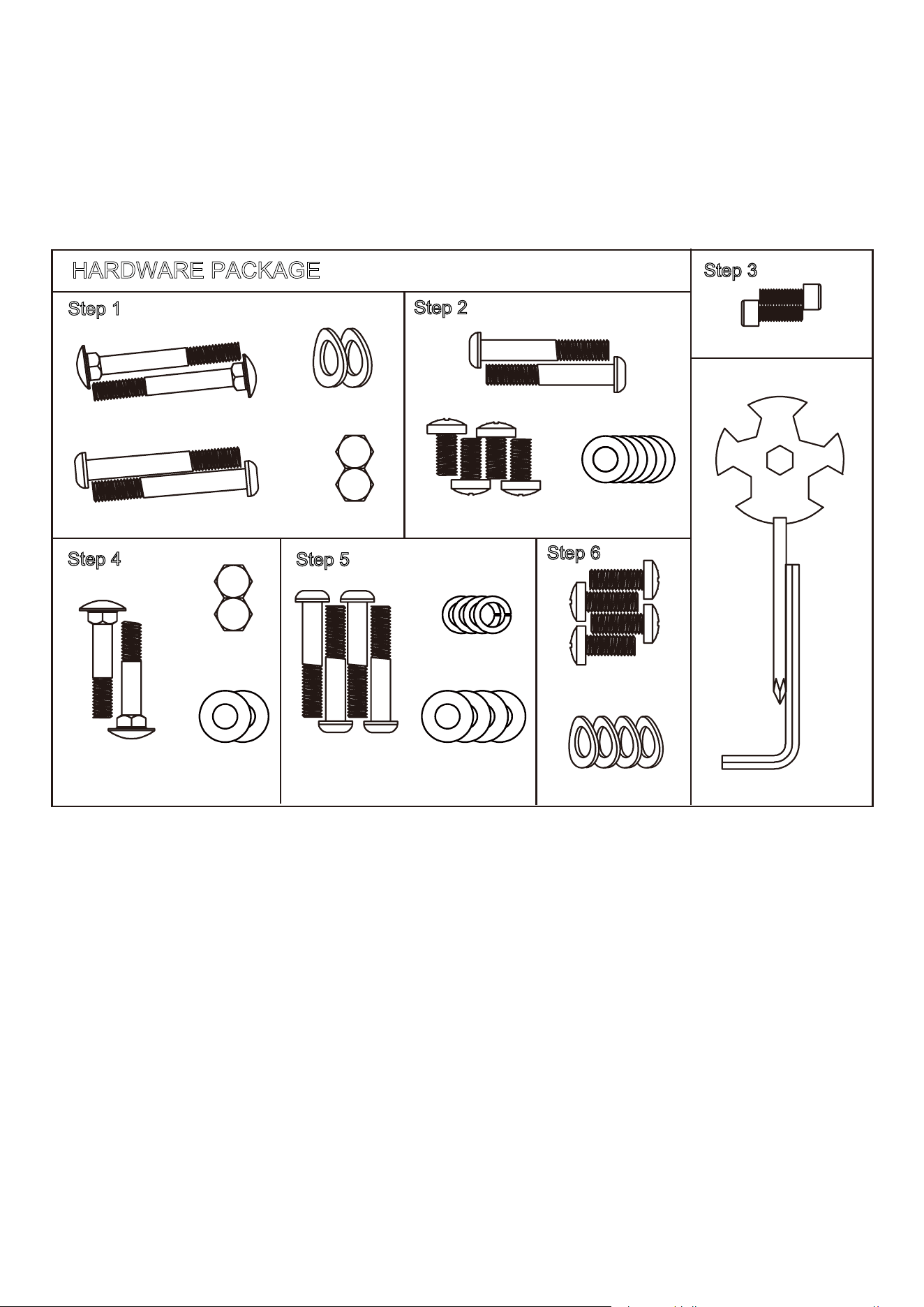
HARDWARE PACKAGE
HARDWARE PACKAGE
#26 Arc Washers
#19 Carriage Bolt 2PCS
#20 Bolts 2PCS
2PCS
#27 Cap Nuts
2PCS
Step 1
Step 2
#29 Bolts 2PCS
#23 Flat Washers
#28 Bolts 2PCS
6PCS
#33 Screws 2PCS
Step 3
#25 Carriage Bolts
2PCS
#27 Cap Nuts
Step 4
2PCS
#23 Flat Washers
2PCS
#22 Bolts 4PCS
#23 Flat Washers
#24 Spring Washers
4PCS
4PCS
Step 5
#21 Bolts 4PCS
#26 ArcWashers
4PCS
Step 6
Spanner Tool
Allen Wrench

6
PARTS LIST
No. Part Name Quantity 45 External magnetic flywheels, 200*7 2.5/3kg 1
1 Main frame 1 46 Bearing 6000z 2
2 Front post 1 47 Tension spring, 18*48, Wire 2 1
3 Front stabilizer 1 48 Tap bolts, 9.8*4*M8*15, similar with BU350 1 1
4 Cushion frame 1 49 Brake handle, 12*380 1
5 Handle bar 1 50 Eccentric shaft, 12*105 1
6 Adjusting tube 1 51 Eccentric wheel, 20*38 1
7 Magnetic board 1 52 Powder metallurgy set, 23*12.2*11 2
8 Idler link 1 53 Lock washer, 30*2 2
9 Rear stabilizer 1 54 Idler spacer, 16
*10.2*10 1
10 Hex tap bolt, M6*70 1 55 Pulley, 240/J6, Hexagon al hole 1
11 Hex nut, M6 2 56 Foam grip for handle bar 1, 3*33*450 2
12 Hex tap bolt, M8*40 1 57 Foam grip for handle bar 2, 3*33*160 2
13 Plastic nut, M8 S13 1 58 End cap for rear stabilizer, with 50 2
14 Hex thin nut, M10*1*H5 2 59 End cap for front stabilizer, with 50 2
15 Taper thin nut, M10*1*H4 2 60 Pedals (left and right) 2
16 Plastic nut, M8 S13 4 61 Round end cap, 25*1.5 tube 4
17 Screws, ST4.2*20 8 62 Leather belt, 370PJ6 1
18 Self-
drilling screws, ST4.2*20 4 63 Seat Cushion, 360*280*40 1
19 Carriage bolt, M8*60, 8, 20 2 64 Backrest cushion, 380*290*40 1
20 Bolts, M8*60, teeth20, S5 2 65 Sleeve, Outer Recipe tube, 80*40*1.5 2
21 Bolts, M8*20, full teeth, S5 4 66 Rectangular end cap, 60*30*1.5 wire 2
22 Bolts, M8*45, 20, S5 4 67 Rectangular end cap, 38*38*1.5 wire 2
23 Flat washers, 16*8.5*1.5 12 68 The thread plug, with 1 2 holes 2
24 Spring wa sher, D8 4 69 Shell 1
25 Carriage bolt, M8*42 2 70 Crank plug 2
26 Arc was
her, 16*8.5*1.5 6 71 Arc idler 43.5*25, included a 6000 Bering 1
27 Cap nut, M8 4 72 Tension control wire, line 280 mm 1
28 Bolts, M8*16, S5 4 73 Tension control wire 55 max/long760mm 1
29 Bolts, M8*50, 20, S5 2 74 Idler wheel, 41*8.5*20 2
30 Screws, M5*8 4 75 Brake block, 40*38*32 1
31 Screws, M8*38, 15 S5 2 76 EV washer, 40*20*3 1
32 Screws, M5*15 2 77 Monitor 1
33 Screws, M6*15 S5 2 78 Trunk Line 1, 600mm 1
34 Lock washers for shafts, D12 1 79 Needle sensor, 500mm, with seat 1
35 Bolts M5*45, fu
ll teeth 1 80 Hand Pu lse Sensors, 700mm 2
36 Arc wa sher, 20*6*1 1 81 Hand pulse wire 1, 600 mm 2
37 Bolts, M5*10, full teeth 2 82 Hand pulse wire 2, 1600mm 2
38 Bead bowl, Ø56*15.5 2 83 Brake handsets 24*77*holes 12 1
39 Crank, 140*220, 1/2 1 84 Bead frame, Ø46*8 2
40 Flywheels spacer,16*10.2*17 1 85 Two groove nut, Ø46*12 teeth on le ft 1
41 Tension spring,18*48, wire2 1 86 Locking washers, Ø46*2 1
42 Black magnet, 40*25*10 9 87 Hex nut, 32*32*4 2
43 Round magnet,15*6, without seat 1 88 Thre
e slot nut, Ø46*12 1
44 Inertia wheel, 10*125*M10*1*17 1 89 Washer, Ø40.5*3 1
7
ASSEMBLY INSTRUCTIONS
1) Preparatory work:
A. Please make sure there has enough space around the machine before assembly.
B. Ensure that you have the right tool.
C. Check the parts and the hardware first.
2) Assembly instructions:
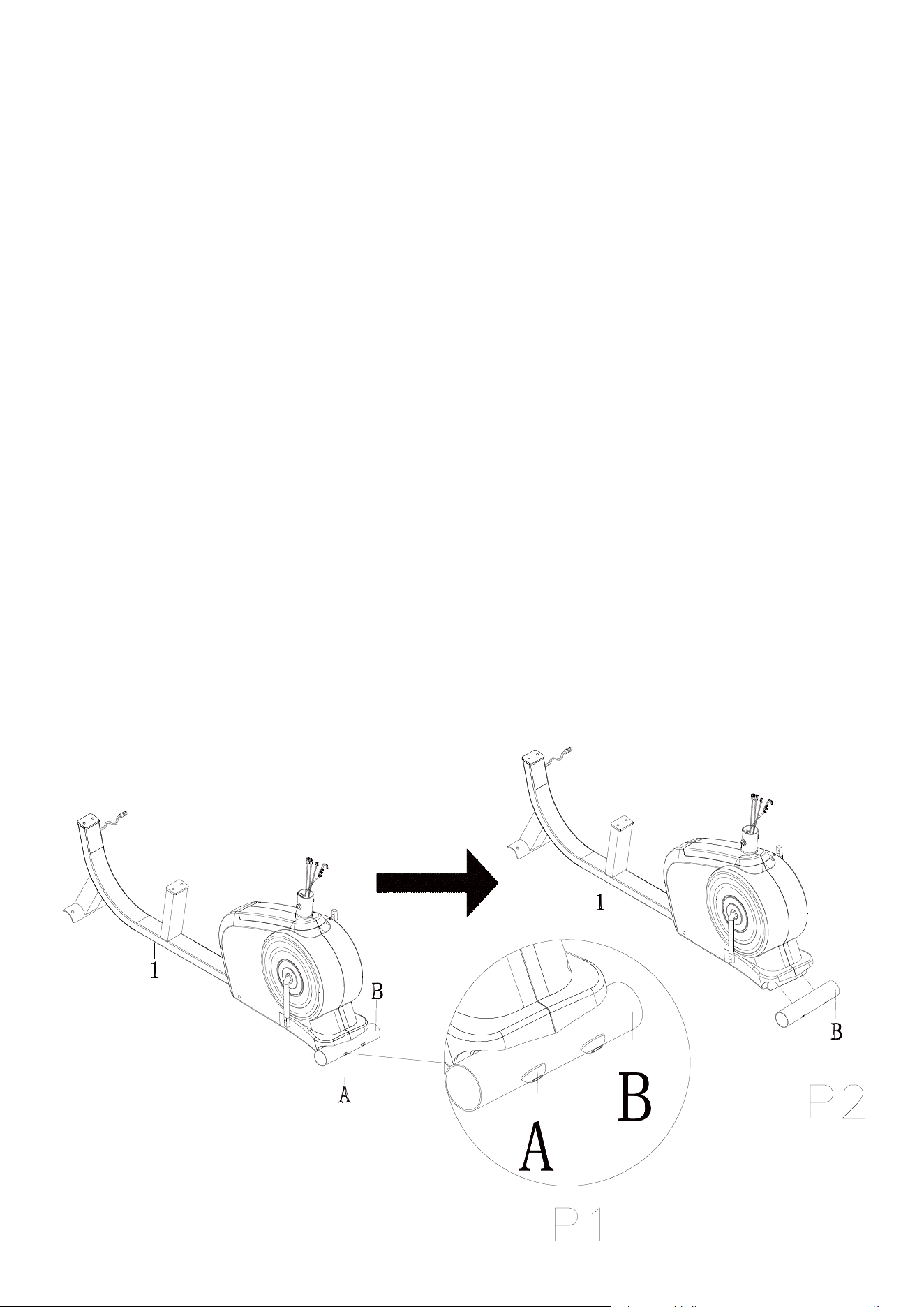
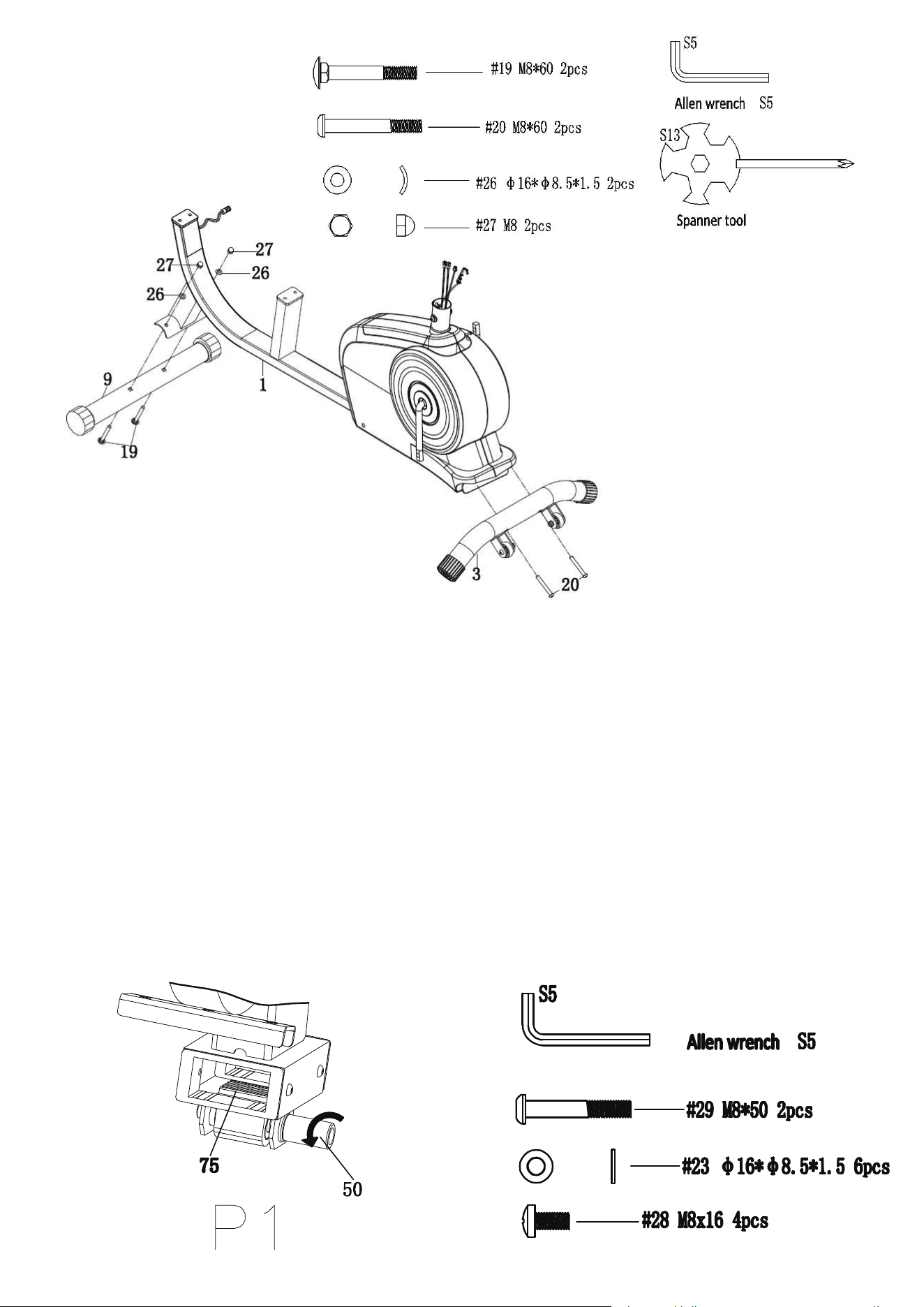
Step1: Install the front and rear stabilizers
Required parts:
The Front Stabilizer(#3), Rear Stabilizer(#9) and the screws and tools in the picture below.
2. Attach the Front Stabilizer (#3) to the Main Frame (#1) using 2 Bolts (# 20) and tighten
them
with the Allen wrench.
3. Attach the Rear Stabilizer (#9) to the Main Frame (#1) using 2 Carriage Bolts (#19), 2 Arc
Washers (#26), and 2 Cap Nuts (#27). Make sure the bolts have been tightly fastened by the
Spanner Tool.
Note: If the ground is flat, place the thicker side of the end cap for t he rear stabilizer (#58) facing up.
Also, the end cap for rear stabilizer( #58) is adjustable, if the machine is located on uneven gro und,
the end cap can be adjusted to make the machine more s
table.
1. Pull out and 2 that prelocked in as Pic 2 .Stabilizer (#B) Bolt (#A) Main Frame (#1)
8
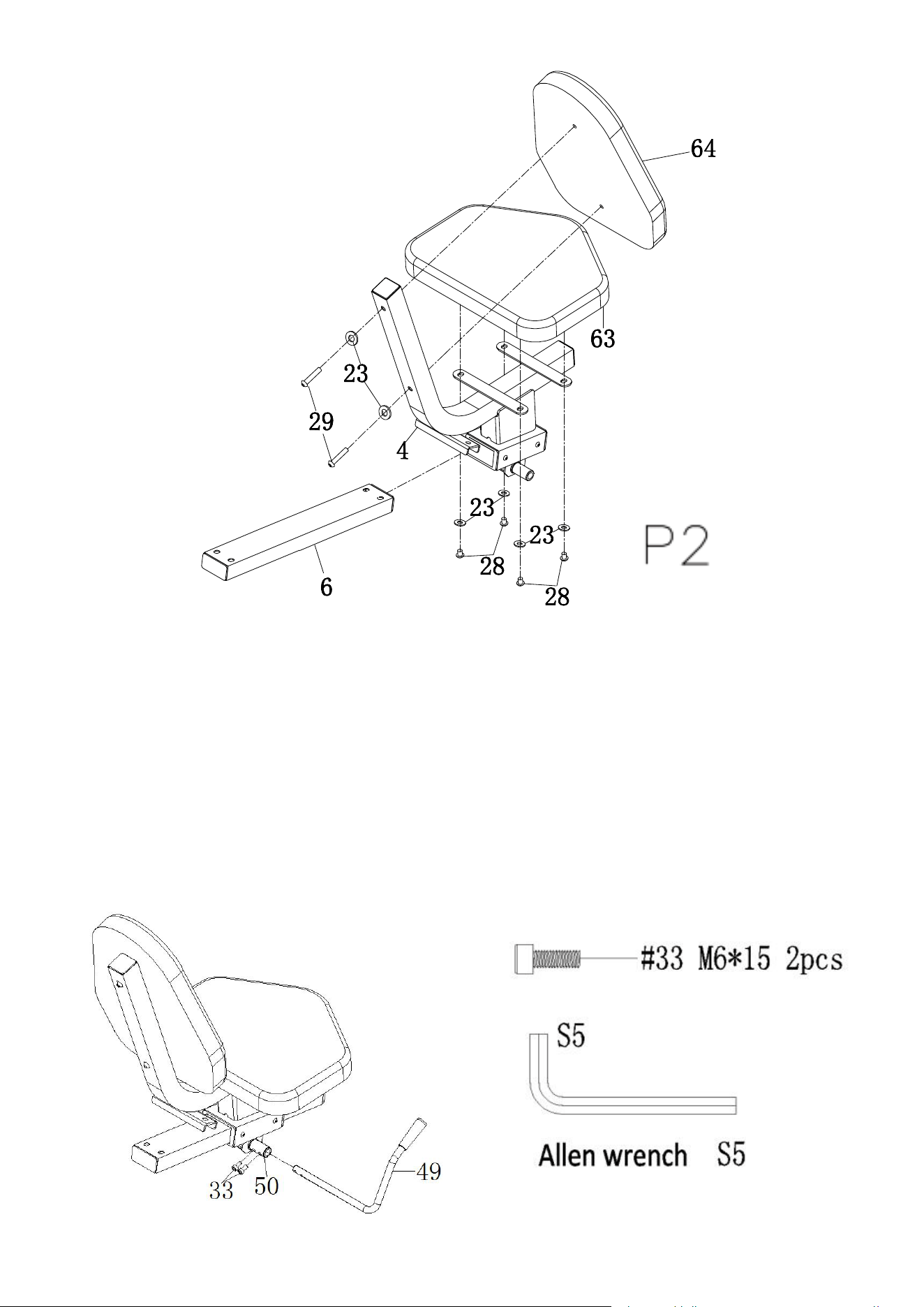
Step 2: Install the seat and backrest cushion
Required parts:
The Seat Cushion (#63), Backrest Cushion (#64) and the screws and tools in the picture below.
1. Rotate Eccentric Shaft (#50) to keep inner plane of Brake block (#75) in line with Pipe orifice
plane of it as Pic 1. Then, insert Adjusting tube (#6) to Brake block (#75) and tighten
Eccentric Shaft (#50) as Pic 2.
2. Attach the Seat Cushion (#63) to the Cushion Frame (#4) using 4 Bolts (#28) and 4 Flat
Washers (#23), making sure the correct side is facing up.
3. Attach the Backrest Cushion (#64) to the Cushion Frame (#4) using 2 Bolts (#29) and 2 Flat
Washers (#23) as shown. Tighten with the Allen Wrench S5.
9
Step 3: Install the brake handle
Required parts:
The Brake Handle (#49), Screws (#33) and the Allen wrench.
Insert the Brake Handle (#49) into the hole of the Eccentric Shaft (#50 ), make sure the correct
side is facing up, and then lock it with the 2 Screws(#33), as shown in the diagram. Tighten with
Allen Wrench S5.
10
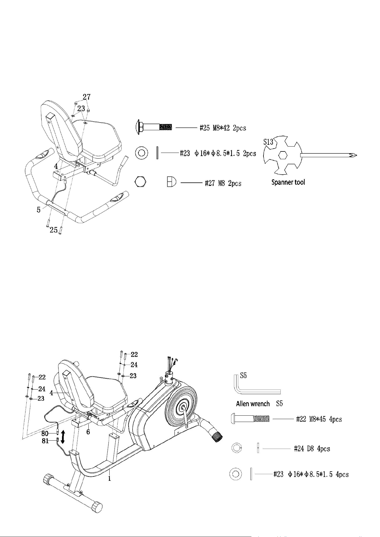
Step 4: Install the handle bar
Required parts:
The Handle Bar (#5) and the screws and tools in the picture below.
Attach the Handle Bar (#5) to the Cushion Frame (#4) using 2 Carriage Bolts (#25), 2 Flat
Washers (#23) and 2 Cap Nuts (#27). Tighten with the Spanner tool.
Step 5: Install the cushion frame
Required parts:
The Cushion Frame (#4) and the screws and tools in the picture below.
1. Attach the Cushion Frame (#4) to the Main Frame (#1) using 4 Bolts (#22), 4 Spring Washers
(#24), and 4 Flat Washers (#23). Tighten with Allen Wrench S5.
2. Connect the Hand Pulse Sensors (#80) with the Hand Pulse Wire (#81), as the diagram
shows.
11
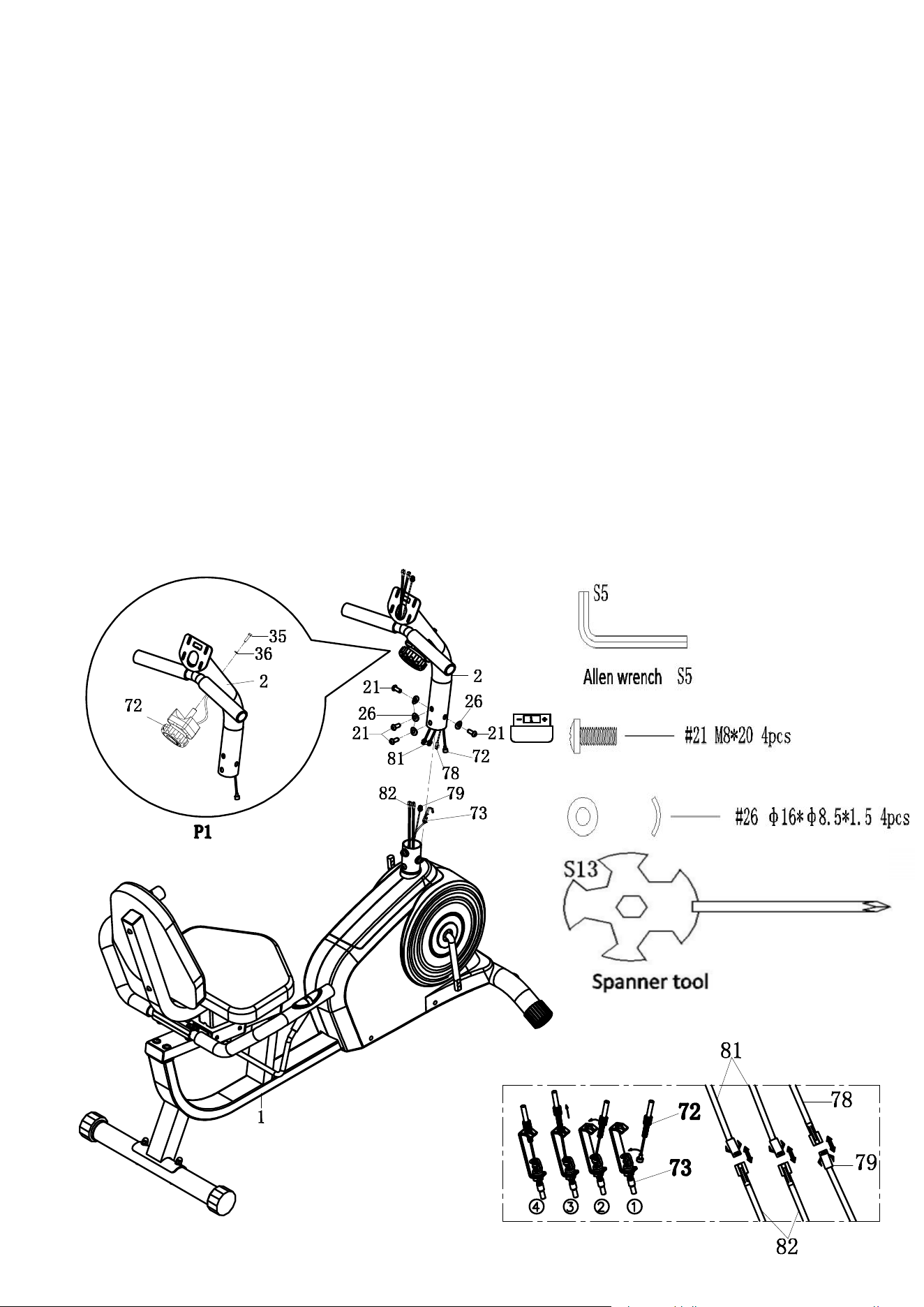
Step 6: Install the front post
Required parts:
The Front Post (# 2), Main Frame (#1), Tension Control Wire (#7 2) and the screws and tools in the
picture below.
1. Pu t the Tension Control Wire (#72) into the Front Post (#2) and lock the tension control knob
by using Arc washer (#36) and Bolts (#35).
2. Connect the Trunk Line (#78) with t he Needle Sensor Line (#79) and connect the Hand Pulse
Wire 1 (#81) with the Ha nd Pulse Wire 2 (#82) as shown.
3. Insert the Te nsion Control Wire (#72) to Tension Control Wire (#73) and then pull it up to
ensure a tight connection.
4. Att ach the Front post (#2) to the Main F r ame (#1) using 4 Bolts (#21), 2 Arc Washers (#26)
and Allen wrench as shown and make sure the screws and the holes are aligned.
Note: Set the Tension Control Kn ob at 1 to en sure the Tension Control Wires (# 72 and #73) can be
easily connected.
12
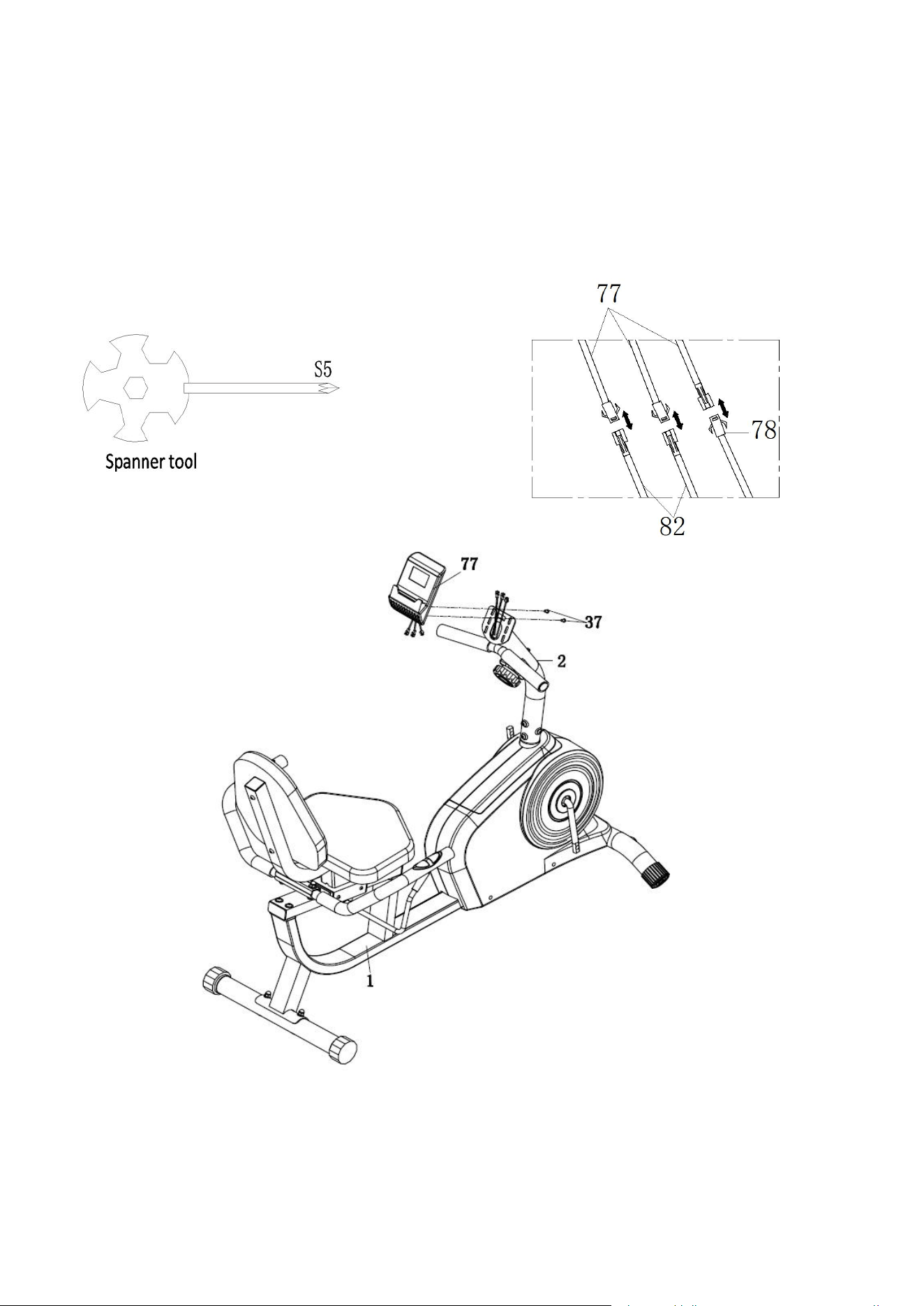
Step 7: Install the computer
Required parts:
The Computer (#77), 2 bolts (#37), and Spanner Tool.
Connect the Computer (#77) lines with the Hand Pulse Wire 2 (#82) and Trunk Line (#78) in turn
as shown. Then attach the Monitor (#77) to the Front Post (#2) using 2 Bolts (#37) and Spanner
tool.
13
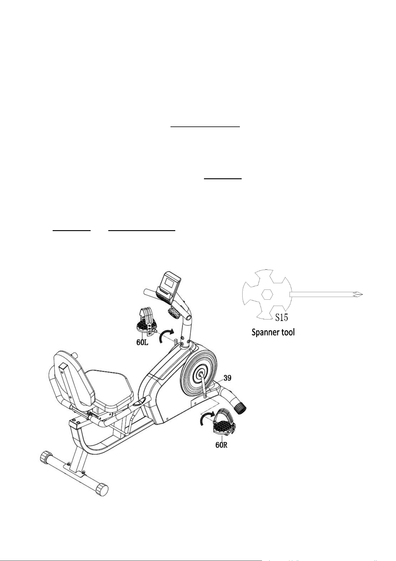
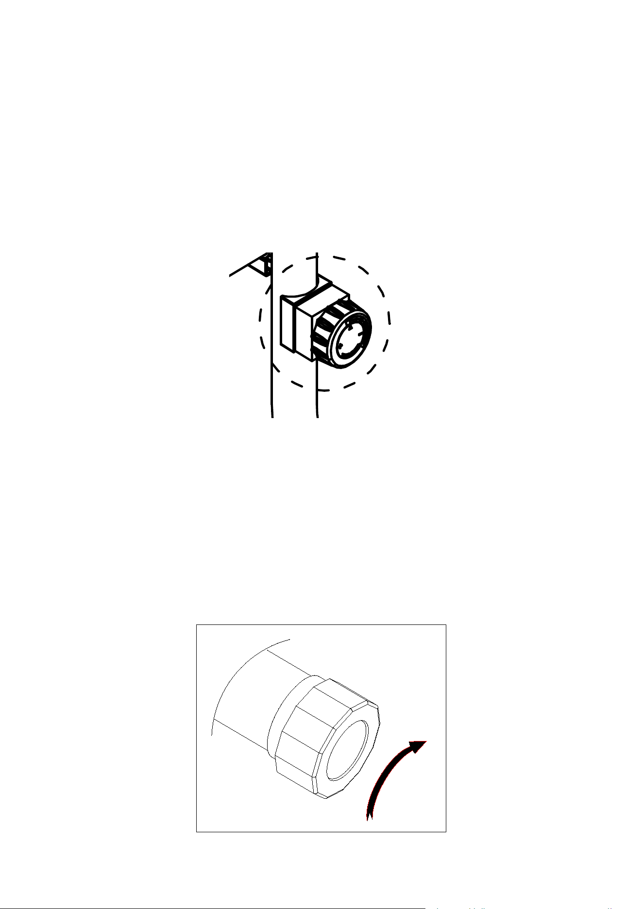
Step 8: Install the left & Right Pedals
Required parts:
The Left & Right Pedal (#60) and Spanner Tool.
Connect the Left & Right Pedal (#60L&R) onto the Left & Right Crank (#39).
Left Pedal: Align the Left Pedal (#60L) with the Left Crank Arm (#39) at 90° and gently insert the
pedal into the crank arm. Turn the pedal counter-clockwise as tightly as you can with your hand
then secure with Spanner Tool.
Right Pedal: Align the Right Pedal (#60R) with the Right Crank Arm (#39) at 90° and gently
insert the pedal into the crank arm. Turn the pedal clockwise as tightly as you can with your hand
then secure with Spanner Tool.
Note: The figure shows the pedal tightening direction overlooking from the rear right perspective,
and the clockwise and counterclockwise in the steps refer to the pedal tightening direction when
we are facing the main frame when installing. It is only due to the difference caused by different
viewing angles, and the pictures are not wrongly marked.
Assembly is complete!
14
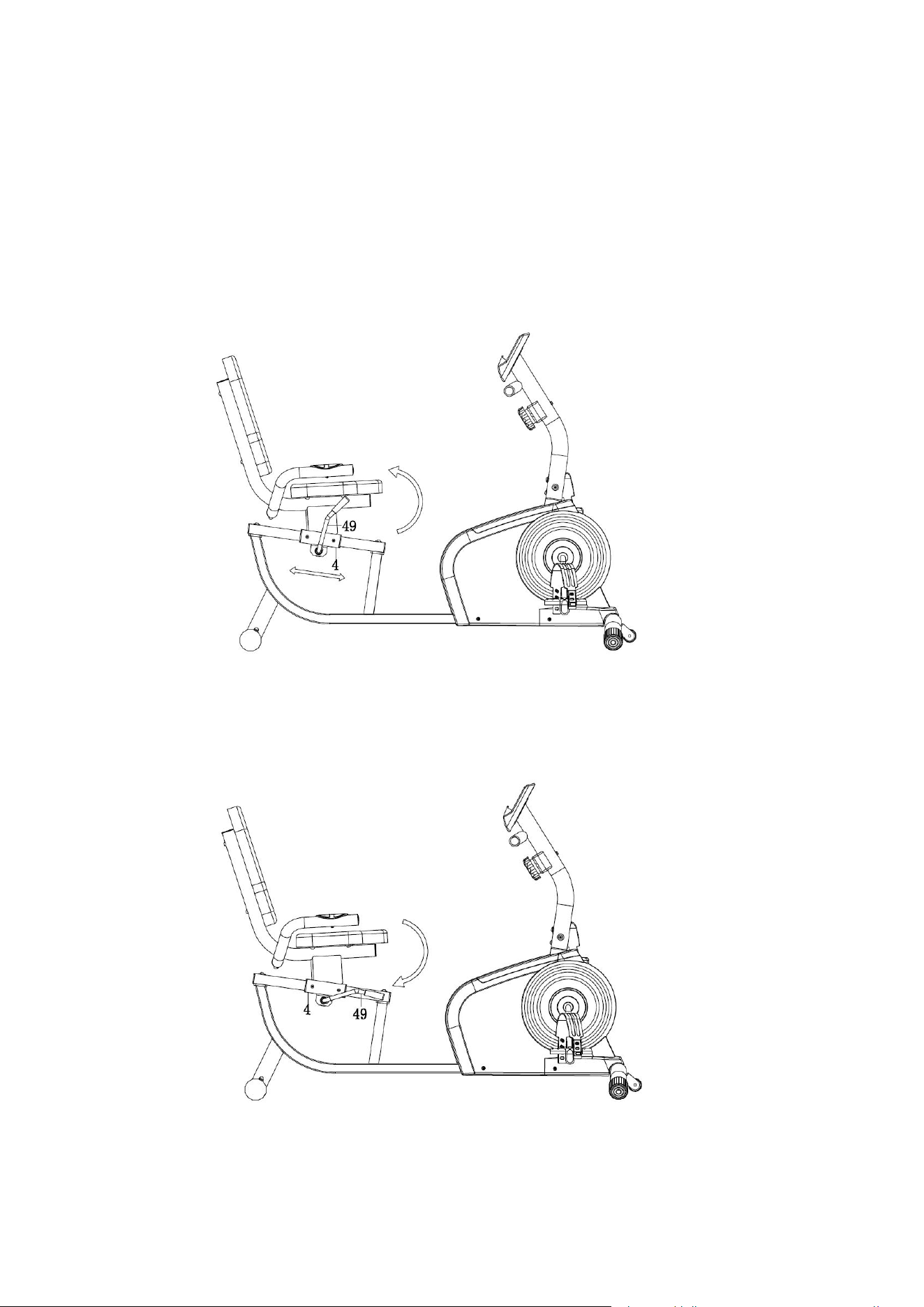
ADJUSTING THE SADDLE
Pull the Brake Handle (#49) up to loosen (see Fig 1). Keep your feet on the floor as
leverage, then move the Cushion Frame (#4) to the desired position. Push the
Brake Handle (# 49) down to tighten (see Fig 2).
Fig. 1
Fig. 2
15
ADJUSTING THE RESISTANCE
Adjust the resistance of the bike using the Tension Control (#72). Increase the level
of resistance by turning the tension knob to the RIGHT (clockwise), decrease the
level of resistance by turning the tension knob to the LEFT (counter-clockwise).
c
b
a
ADJUSTING THE HEIGHT AND BALANCE
In order to achieve a smooth and comfortable ride, you must ensure that the bike is
stable. If you notice that the bike is unbalanced during use, you should adjust the end
caps located beneath the Rear Stabilizer (#9). To do so, turn it clockwise.
16
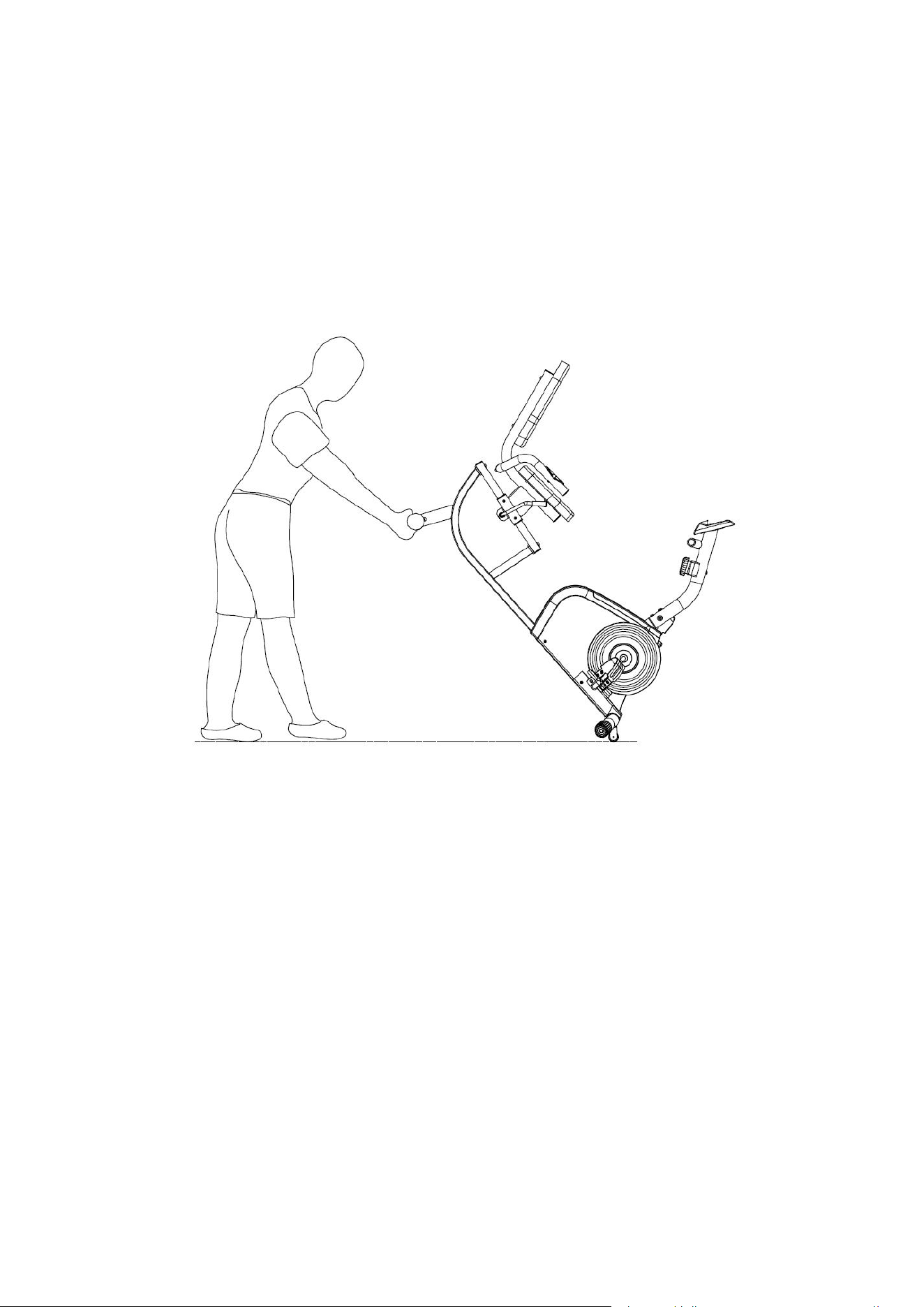
HOW TO MOVE THE BIKE
Hold the Rear Stabilizer (#3) and lift the bike until wheels on the Front Stabilizer
(#9) touch the ground. Now you can wheel the bike to the desired location.