
OWNER’S MANUAL
4118.5-021721
RECUMBENT BIKE
IMPORTANT: Read all instructions carefully before using this product. Retain this
owner’s manual for future reference. The specifications of this product may vary from
this photo and, subject to change without notice.

PLEASE DO NOT RETURN THIS PRODUCT TO THE STORE.
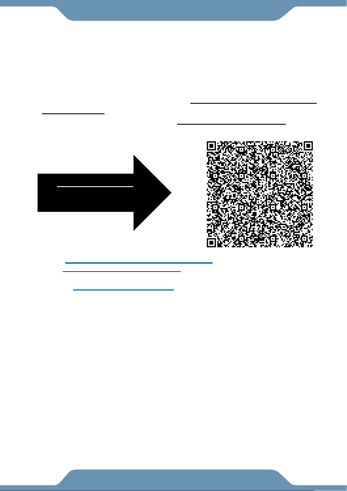
Automatically set up an Email
to CUSTOMER SERVICE by
SCANNING this QR code with
the Camera or a QR code
scanner APP on your smart
device.
See the Service Page for other methods of contacting Customer Support.

1
TABLE OF CONTENTS
SERVICE .......................................................................................................................... 2
LABEL PLACEMENT ........................................................................................................ 2
IMPORTANT SAFETY GUIDELINES ................................................................................ 2
PARTS LIST ...................................................................................................................... 2
HARDWARE & TOOLS PACK .......................................................................................... 2
ASSEMBLY ....................................................................................................................... 2
CONSOLE ........................................................................................................................ 2
ADJUSTMENTS ............................................................................................................... 2
MAINTENANCE & TROUBLESHOOTING ........................................................................ 2
WARRANTY ..................................................................................................................... 2
PARTS REQUEST FORM ................................................................................................ 2
2
SERVICE
IMPORTANT: FOR NORTH AMERICA ONLY
For damaged or defective product, questions, replacement parts or any other service
support, please contact our customer service department using one of the below
methods:
1. Scan the QR code with the camera or any QR code
scanner app on your smart device. This will bring you
to a direct email to send to CUSTOMER SERVICE in the
format shown below for your equipment.
2. Email: service@paradigmhw.com
a. Response Time: 1-2 Business Days
3. Website: www.paradigmhw.com
4. Phone: Toll-Free: 1-844-641-7921
a. Monday thru Friday (PST)
b. Response time may vary via calling
c. Refer to our email for the best response time
Please have the following information ready when requesting for
service:
Your name
Shipping Address
Phone number
Model number
Serial number
Part number
Proof of Purchase
Paradigm Health & Wellness, Inc.
1189 Jellick Ave.
City of Industry, CA 91748, USA
Fastest and Easiest
method to set up a
customer service response
3
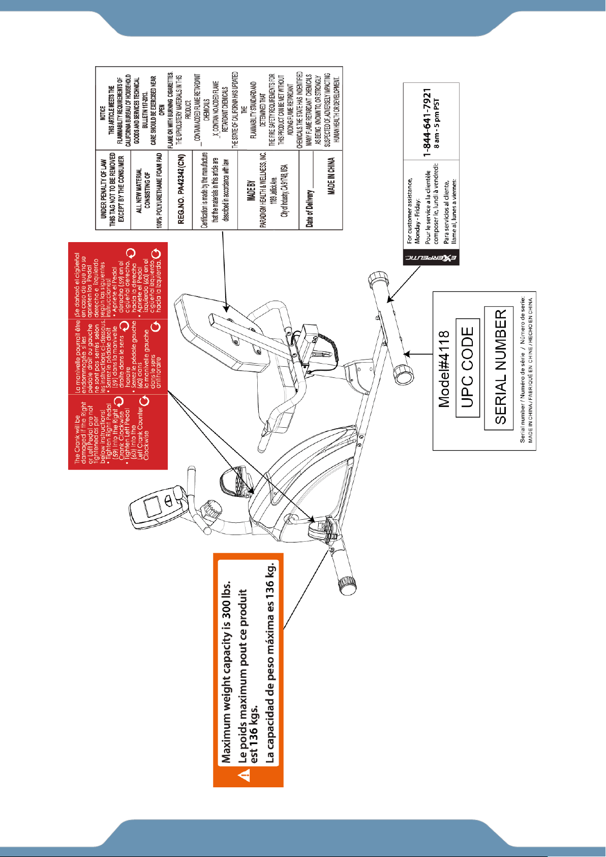
LABEL PLACEMENT

4
IMPORTANT SAFETY GUIDELINES
Read all guidelines before using this machine. When using this machine,
basic precautions should always be followed, including the following:
WARNING - To reduce the risk of injury to persons:
1. Make sure your equipment is correctly assembled before you use it.
2. Be sure all screws, nuts, and bolts are tightened prior to use.
3. Before using this equipment, we recommend doing warm ups.
4. Only one person should be using the equipment at a time.
5. Never operate this Equipment if it is damaged, if it is not working properly, has been dropped, or
damaged. If a problem is encountered contact Customer Service before using the equipment
again.
6. Always use this equipment on a clear and level surface.
7. For household use only.
8. Do not use outdoors or near water.
9. Use the machine only for its intended use as described in this manual. Do not use attachments
not recommended by the manufacturer.
10. Do not wear loose clothing when using the equipment.
11. Never drop or insert any object into any opening.
12. If at any time you feel faint, light-headed, or dizziness while operating the equipment, stop
exercising immediately. You should also stop exercising if you are experiencing pain or any
discomfort.
13. For any problems contact customer service. Servicing should be performed by an authorized
service representative. Our contact number is on the service page.
14. This product requires a minimum of 6 square feet of space for safe operation.
15. Be careful to always hold onto the handlebars when you’re mounting and dismounting.
16. Be careful to have the pedals at their lowest point when stepping off.
17. Hold onto the handlebars and use both the pedals in tandem to ensure a smooth, effective
workout.
18. Warning: - Risk of Personal Injury - Consult with your personal physician to see if exercise
equipment is appropriate for you. This is especially important for people with pre-existing health
problems. Do not use this equipment without your physician's approval.
19. Warning: - Risk of Personal Injury – Do not allow children to use this machine.
20. Warning: - Risk of Personal Injury - Keep children under the age of 13 away from the
machine.
21. Warning: - Risk of Personal Injury – Keep body parts, hair, loose clothing, and jewelry
clear of all moving parts.
22. Warning: - Risk of Personal Injury - Do not attempt to service the unit yourself.
Discontinue use and contact customer service.
23. Warning: - To Reduce The Risk Of Personal Injury - Read And Understand All Read The
Instructions Before Using This Machine

5
The product weighs more than 44 lbs. It is heavily
recommended that at least 2 persons assemble.
IMPORTANT SAFETY GUIDELINES
Consult with your personal physician beore using this equipment if you have any of the
following conditions or ailments:
Pregnancy
Extreme obesity
Middle ear infection
Hiatus hernia or Ventral hernia
Glaucoma, retinal detachment or conjunctivitis
Use of anticoagulants including Aspirin in high doses.
Spinal injury, Cerebral Sclerosis, or acutely swollen joints
Heart or circulatory disorders for which you are being treated
High blood pressure, Hypertension, Recent stroke or Transient Ischemic attack
Bone weaknesses including Osteoporosis, Unhealed fractures, Modular pins, or surgically
implanted orthopedic supports.
DO NOT EXCEED THE MAXIMUM RATED WEIGHT CAPACITY
The Maximum Weight Capacity for this product is 300 lbs/136 kgs.
SAVE THESE GUIDELINES
!
6
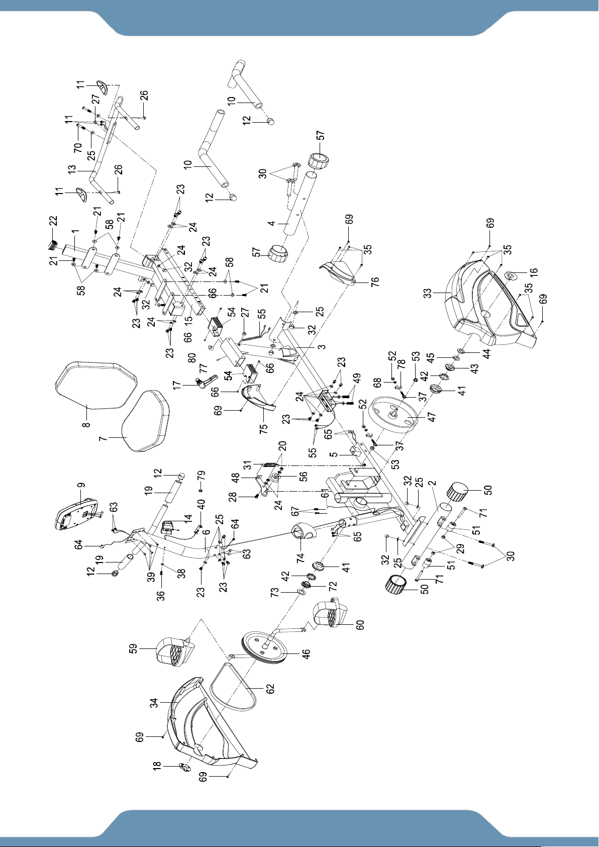
OVERVIEW DRAWING

7
PARTS LIST
No.
Description
Qty
No.
Description
Qty
1
Back and Seat Support Bracket
53x23x2.0
1
28
Bolt M8x18
1
2
Front Stabilizer Ø60x1.5x580
1
29
Locknut M6
2
3
Rear Main Frame
1
30
Bolt M8x70
4
4
Rear Stabilizer Ø60x1.5x580
1
31
Spring
1
5
Front Main Frame 80x40x2
1
32
Cap Nut M8
6
6
Front Handlebar Post Ø50x1.5
1
33
Left Cover
1
7
Seat Cushion
1
34
Right Cover
1
8
Back Cushion
1
35
Screw ST4.2x25
8
9
Console (0520)
1
36
Bolt M5x25
1
10
Handlebar Foam Grip
Ø30xØ24x510
2
37
Adjustable Bolt M6x33
2
11
Hand Pulse Sensor
2
38
Big Curve Washer Ø5
1
12
Round End Cap for Handlebar
Ø25x1.5
4
39
Bolt M5x10
4
13
Handlebar Ø25x1.5
1
40
Tension Cable L=1000mm
1
14
Tension Control Knob
1
41
Axle Bush
2
15
Seat Sliding Tube 23x53x1.5
1
42
Bearing
2
16
Left Cover Cap Ø60xØ24x2
1
43
Axle Sleeve I 15/16"
1
18
Right Cover Cap Ø60xØ24x2
1
44
Nut 7/8"
1
19
Front Handlebar Foam Grip
Ø30xØ24x160
2
45
Washer Ø34.5xØ23x25
1
20
Nylon Nut M8
2
46
Crank Ø200
1
21
Bolt M6x15
8
47
Flywheel Ø230
1
22
Backrest and Seat Support
Bracket End Cap 23x53x1.5
1
48
Idle Wheel Bracket
1
23
Bolt M8x15
16
49
Bolt M8x30
2
24
Washer Ø8
18
50
Front Stabilizer End Cap Ø60
2
25
Curve Washer Ø8
10
51
Transport Wheel Ø23xØ6x32
2
26
Screw ST4.2x20
2
52
Nut M6
2
27
Wire Plug Ø12.1
2
53
Nut M10x1
2

8
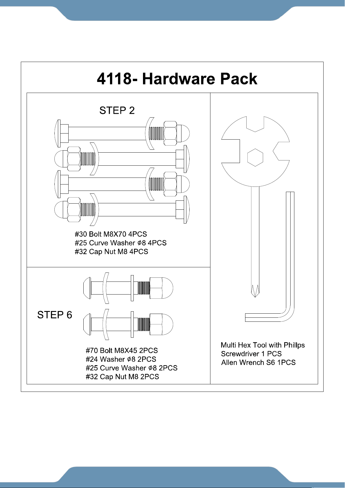
HARDWARE & TOOLS PACK
PARTS LIST
No.
Description
Qty
No.
Description
Qty
54
Bushing
2
70
Bolt M8x45
2
55
Middle Section Hand Pulse
Sensor Wire
1
71
Bolt M6x48
2
56
Idle Wheel
1
72
Axle Sleeve II
1
57
Rear Stabilizer End Cap Ø60
2
73
Washer 7/8"
1
58
Washer Ø6
8
74
Front Handlebar Post Cover
1
59
Right Foot Pedal YH-30X
1
75
Right Rear Main Frame Cover
1
60
Left Foot Pedal YH-30X
1
76
Left Rear Main Frame Cover
1
61
Sensor with Wire L=500mm
1
78
U Bracket
2
62
Belt 340J6
1
79
Spring Washer Ø6
2
63
Extension Wire L=350mm
1
80
Clip
1
64
Extension Sensor Wire L=350mm
1
81
Knob M16x1.5
1
65
Extension Hand Pulse Sensor
Wire L=1800mm
1
82
Phillips Self-Tapping Screw
ST4.2x6
4
67
Pan Head Phillips Self Drilling
Screw ST3x12
2
83
Hex Screw M6x8
1
69
Pan Head Phillips Self Drilling
Screw ST4.2x25
6
84
Baffle Plate
1
9
HARDWARE & TOOLS PACK
10
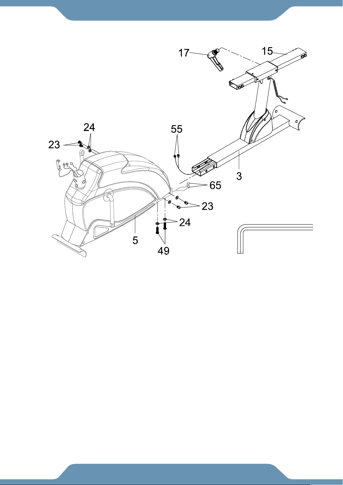
ASSEMBLY
Step 1
1A. Removing the Hardware from the Rear Main Frame - Remove two Bolts (49), four Bolts
(23), and six Washers (24) from the Rear Main Frame (3). Remove bolts with the 6mm Allen
Wrench provided.
1B. Installing the Rear Main Frame - Connect the Middle Section Hand Pulse Sensor Wires
(55) from the Rear Main Frame (3) to the Extension Hand Pulse Sensor Wires (65) from the
Front Main Frame (5). Attach the Rear Main Frame (3) into the Front Main Frame (5) with two
Bolts (49), four Bolts (23), and six Washers (24) that were removed. Tighten bolts with the
6mm Allen Wrench provided.
1C. Adjust the seat position and insert the Knob (81) in the clockwise direction to tighten.
6mm Allen Wrench
Tool:
11
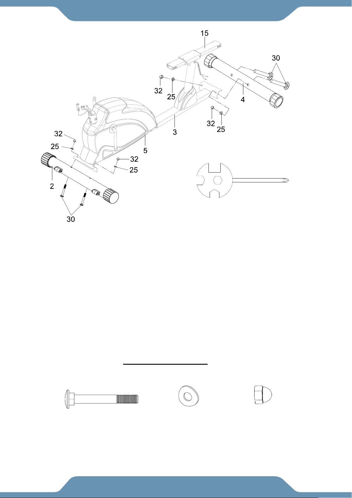
ASSEMBLY
STEP 2
2A. Installing the Front Stabilizer - Position the Front Stabilizer (2) in front of the Front Main
Frame (5) and align bolt holes. Attach the Front Stabilizer (2) onto the front curve of the Front
Main Frame (5) with two Bolts (30), two Curve Washers (25), and two Cap Nuts (32). Tighten
Cap Nuts (32) with the Multi Hex Tool with Phillips Screwdriver provided
2B. Installing the Rear Stabilizer - Position the Rear Stabilizer (4) behind the Rear Main Frame
(3) and align bolt holes. Attach the Rear Stabilizer (4) onto the rear curve of the Rear Main
Frame (3) with two Bolts (30), two Curve Washers (25), and two Cap Nuts (32). Tighten Cap
Nuts (32) with the Multi Hex Tool with Phillips Screwdriver provided
.
HARDWARE PACK
Tool:
Multi Hex Tool with Phillips
Screwdriver
(25) Curve Washer
4 PCS
(32) Cap Nut
4 PCS
(30) Bolt
4 PCS
12
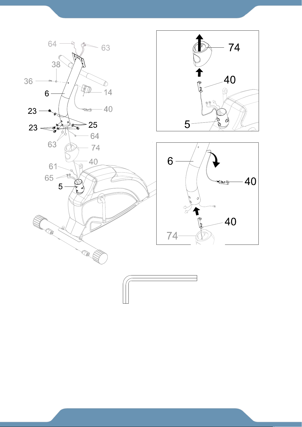
ASSEMBLY
STEP 3
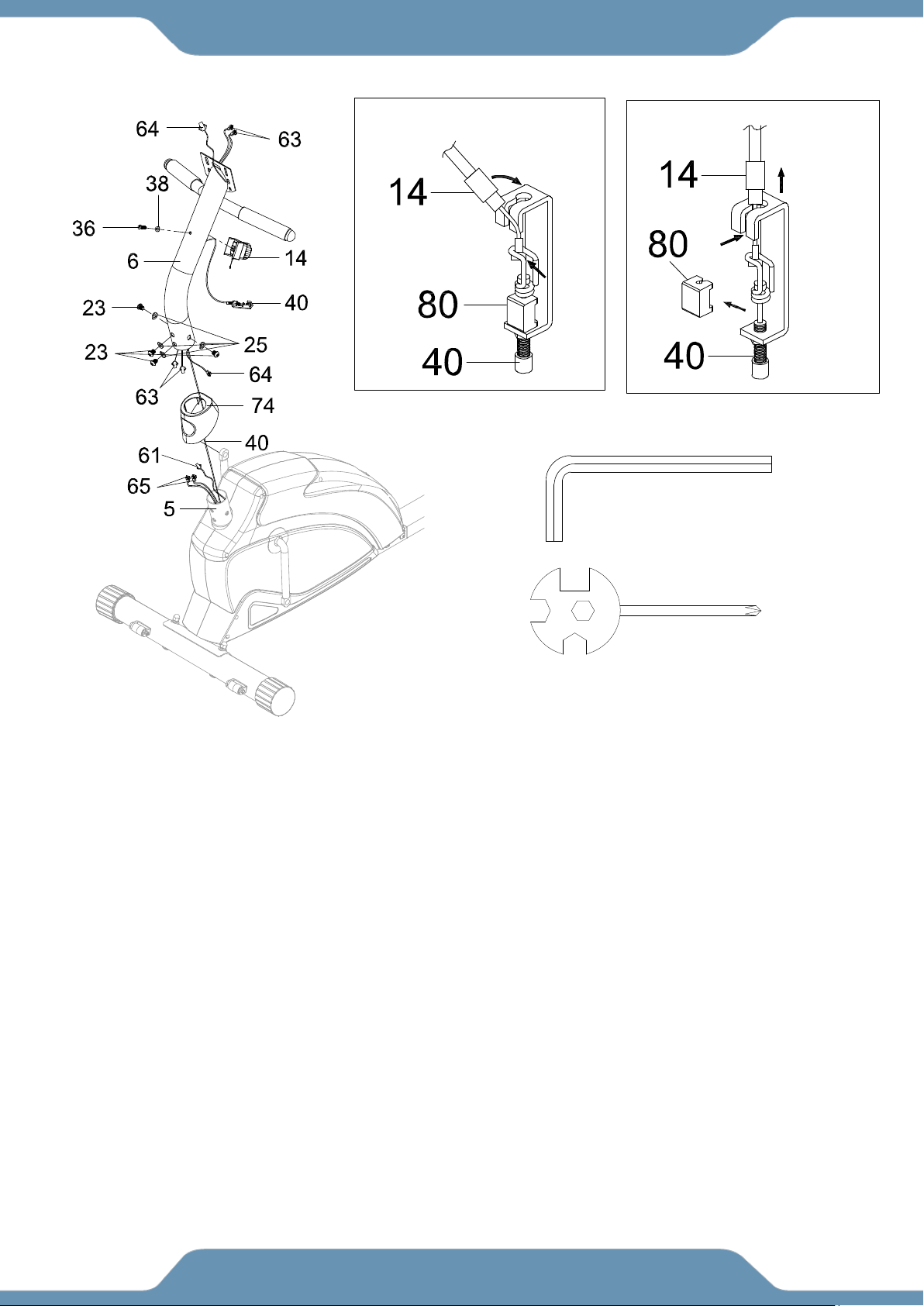
3A. Removing The Hardware From The Front Post – Remove four Bolts (23) and four
Curve Washers (25) from the Front Main Frame (5).
3B. Slide the Front Handlebar Post Cover (74) up and pull the Tension Cable (40) through
the bottom hole. See Figure A.
3C. Insert the Tension Cable (40) into the bottom of the Front Handlebar Post (6) and pull it
out through the square hole located on the Front Handlebar Post (6). See Figure B.
!
6 mm Allen Wrench
Tool:
Fig. A
Fig. B
13
ASSEMBLY
Step 4
4A. Connecting The Console Wires –Connect the Sensor Wire (61) and Extension Hand
Pulse Sensor Wires (65) from the Front Main Frame (5) to the Extension Sensor Wire (64)
and Extension Wires (63) from the Front Handlebar Post (6). Tuck the excess cable into the
Front Main Frame (5).
4B. Installing The Front Post –Insert the Front Handlebar Post (6) onto the tube of the Front
Main Frame (5) and secure with four Bolts (23) and four Curve Washers (25) that were
removed. Slide the Front Handlebar Post Cover (74) down to the Front Main Frame (5).
Remove the Bolt (36) and Big Curve Washer (38) from the Tension Control Knob (14).
4C. Installing the Tension Control Knob – Set the Tension Control Knob (14) to the highest
tension to extend the resistance cable. Place the exposed resistance cable of the Tension
Control Knob (14) into the spring hook of the Tension Cable (40). See Fig. A. Pull the
resistance cable of the Tension Control Knob (14) up until it is seated firmly into the gap
found on top of the metal bracket on the Tension Cable (40), then remove the Clip (80). See
Fig.B. Attach the Tension Control Knob (14) onto the Front Handlebar Post (6) with the
Bolt (36) and Big Curve Washer (38) that were removed.
Fig. A
Fig. B
6 mm Allen
Wrench
Tool:
Multi Hex Tool with
Phillips Screwdriver
14
ASSEMBLY
STEP 5
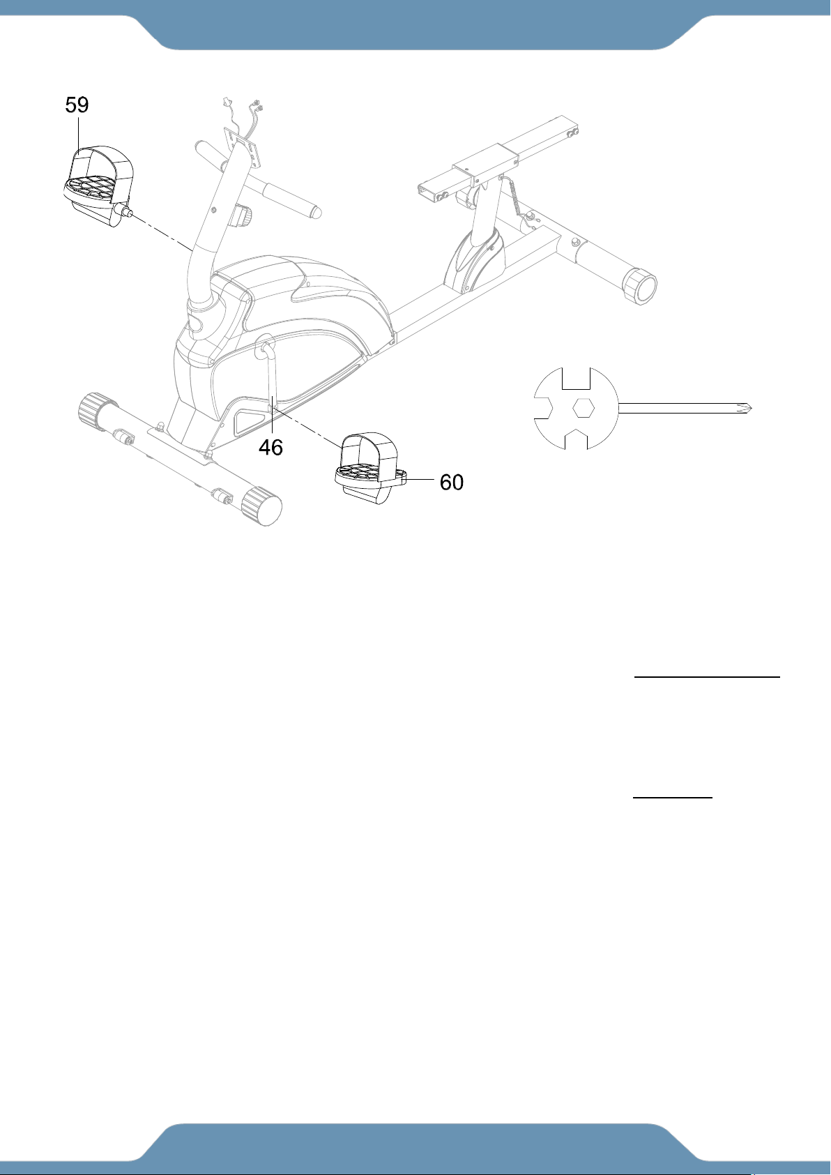
Note: The Cranks, Foot Pedals, Pedal Shafts and Pedal Straps are marked “R” for Right
and “L” for Left.
5A. Installing the Left Pedal: Insert the threaded shaft of the Left Foot Pedal (60) into the
threaded hole on the Left Crank (46). Turn the pedal shaft by hand in a counter-clockwise
direction until snug. Finish off the tightening of the Left Foot Pedal (60) in the same direction
as instructed with the Multi Hex Tool with Phillips Screwdriver.
5B. Installing the Right Pedal: Insert the threaded shaft of the Right Foot Pedal (59) into the
threaded hole on the Right Crank (46). Turn the pedal shaft by hand in a clockwise direction
until snug. Finish off the tightening of the Right Foot Pedal (59) in the same direction as
instructed with the Multi Hex Tool with Phillips Screwdriver.
WARNING: Tighten the pedal shaft in the direction instructed for the Right Foot Pedal (59) and
Left Foot Pedal (60). Failing to do so may strip the threads on the pedal shafts. Insert the pedal
shaft of Left Foot Pedal (60) into threaded hole in the Left Crank (46). Turn the pedal shaft by
hand in the counter-clockwise direction until snug.
Note: DO NOT turn the pedal shaft in the clockwise direction, doing so will strip the threads.
Multi Hex Tool with Phillips
Screwdriver
Tool:
15
ASSEMBLY
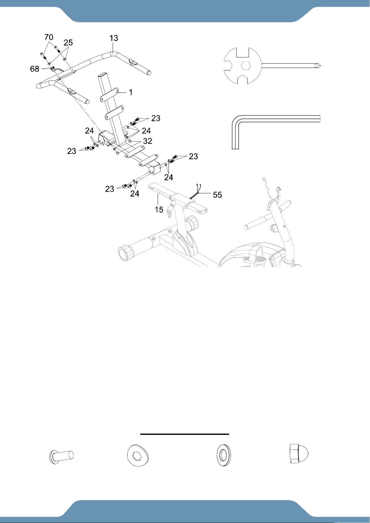
STEP 6
6A. Removing Hardware- Remove eight Bolts (23) and eight Washers (24) from the Back/Seat
Support Bracket (1) and Seat Sliding Tube (15). Remove bolts with the 6mm Allen
Wrench provided.
6B. Installing the Seat Sliding Tube - Insert the Seat Sliding Tube (15) into the Bushings (54)
of the Rear Main Frame (3). Attach the Seat Sliding Tube (15) to the Back and Seat
Support Bracket (1) with eight Bolts (23) and eight Washers (24) that were removed.
Tighten bolts with the 6mm Allen Wrench provided.
6C. Instalilng the Handlebar –Attach the Handlebar (13) onto the Back and Seat Support
Bracket (1) with two Bolts (70), two Curve Washers (25), two Washers (24), and two Cap
Nuts (32). Tighten bolts with the Multi Hex Tool with Phillips Screwdriver provided.
Connect the Middle Section Hand Pulse Sensor Wires (55) from the Rear Main Frame (3)
to the Hand Pulse Sensor Wire (68) from the Handlebar (13).
HARDWARE PACK
Tool:
Multi Hex Tool with Phillips
Screwdriver
(70) Bolt
2 PCS
(25) Curve Washer
2 PCS
(24) Washer
2 PCS
(32) Cap Nut
2 PCS
6mm Allen Wrench
16
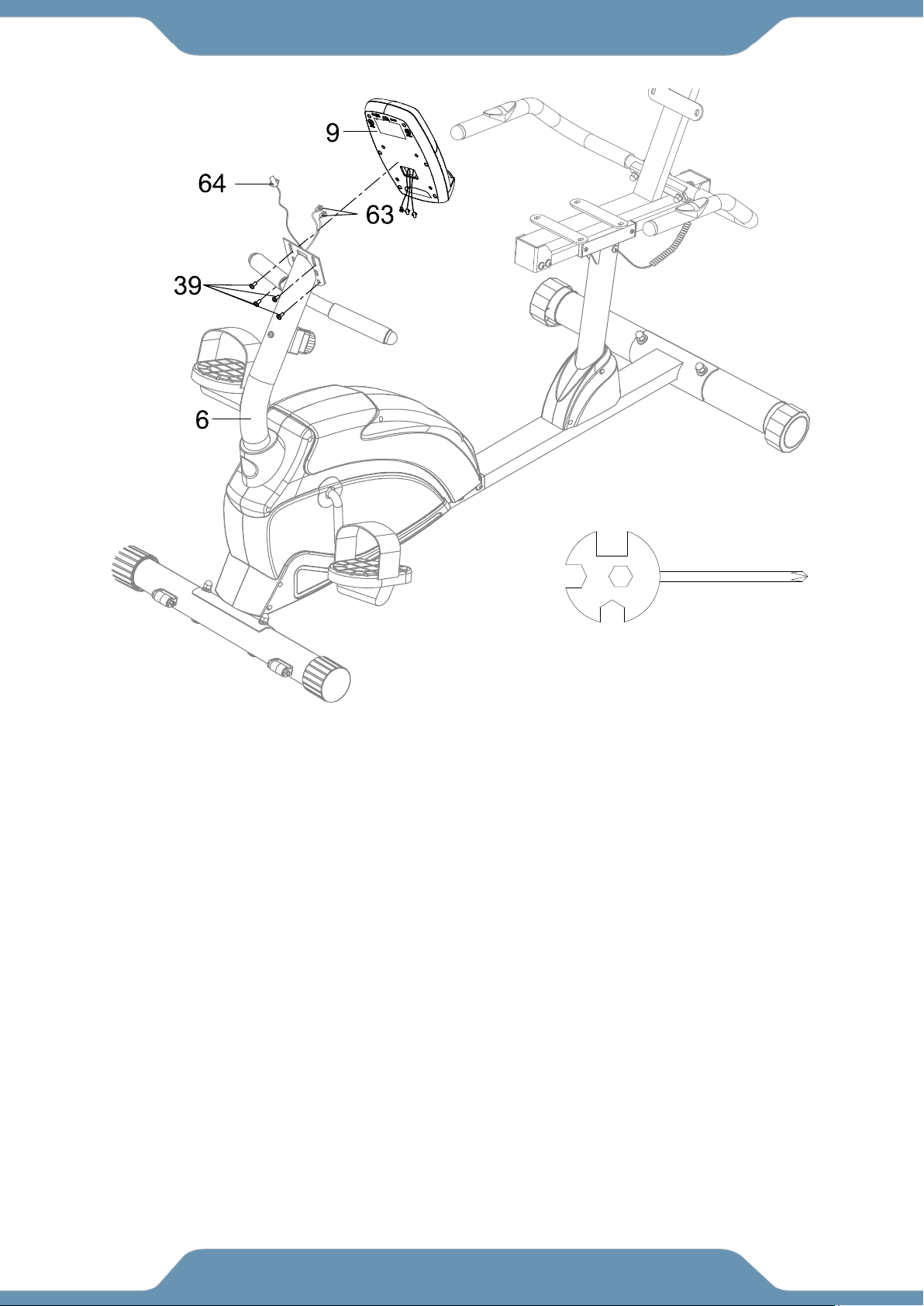
ASSEMBLY
STEP 7
7A. Removing Hardware- Remove four Bolts (39) from the Computer (9). Remove bolts with the
Multi Hex Tool with Phillips Screwdriver provided.
7B. Installing the Console -- Connect the Extension Wires (63) and Extension Sensor Wire
(64) to the wires that come from the Console (9). Tuck wires into the Front Handlebar Post
(6).Attach the Console (9) onto the top end of the Front Handlebar Post (6) with four Bolts
(39) that were removed. Tighten bolts with the Multi Hex Tool with Phillips Screwdriver
provided.
Tool:
Multi Hex Tool with Phillips
Screwdriver
17
ASSEMBLY
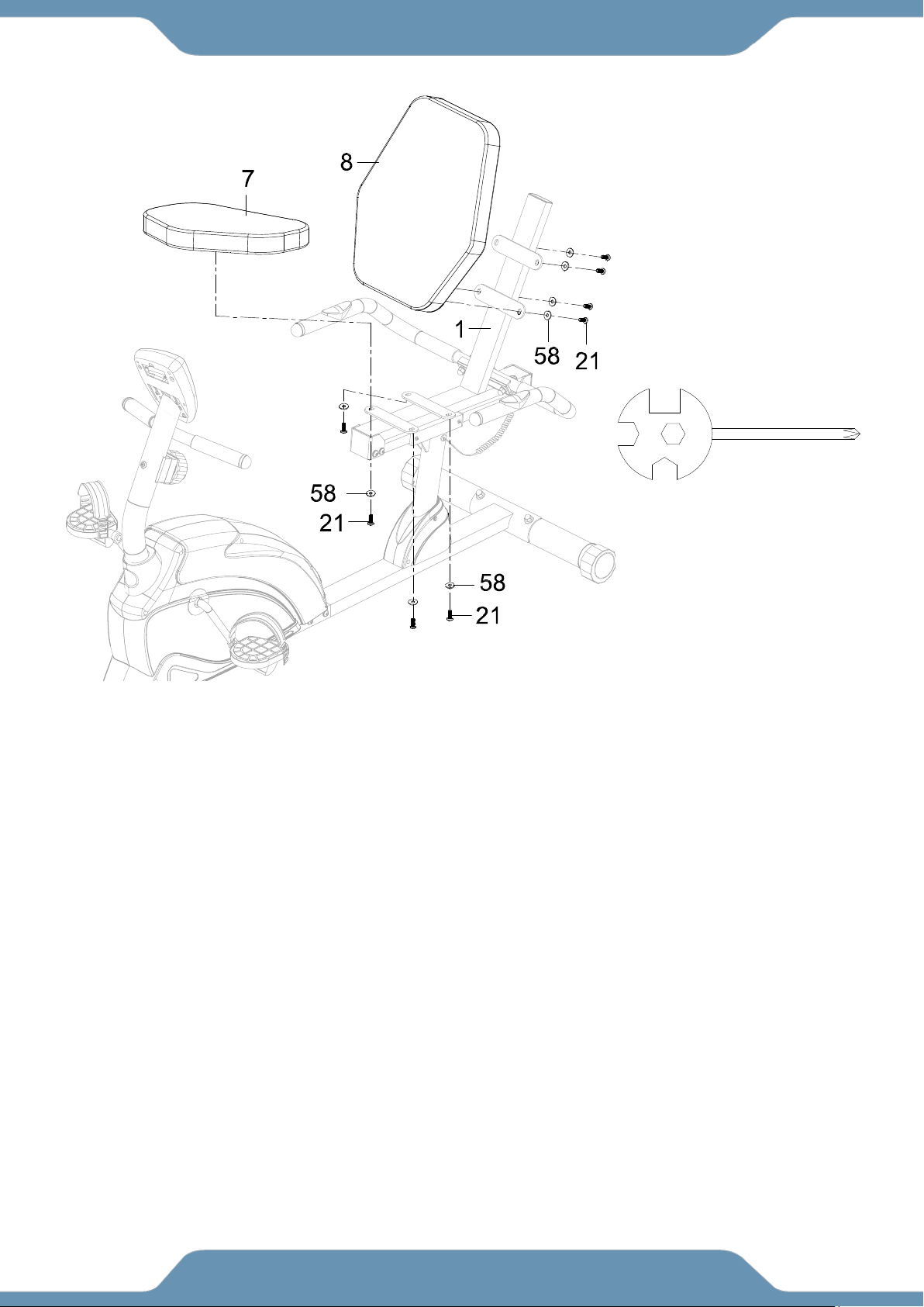
STEP 8
8A. Removing Hardware - Remove eight Bolts (21) and eight Washers (58) from the back of the
Seat and Back Cushions (7, 8). Use the Multi Hex Tool with Phillips Screwdriver
provided.
8B. Installing the Seat and Back Cushion - Attach the Seat and Back Cushions (7, 8) onto the
Back and Seat Support Bracket (1) with eight Bolts (21) and eight Washers (58) that were
removed. Tighten bolts with the Multi Hex Tool with Phillips Screwdriver provided.
Tool:
Multi Hex Tool with Phillips
Screwdriver

18
CONSOLE
HOW TO INSTALL THE BATTERIES:
1. Remove the battery cover at the rear of computer.
2. Place two "SIZE-AA" batteries into the battery housing.
3. Insure batteries are correctly positioned and battery springs are in proper contact with the
batteries.
4. Re-install the battery cover.
5. If the display is illegible or only partial legible, remove batteries and wait 15 seconds
before reinstalling.
OPERATING THE COMPUTER
SPECIFICATIONS:
TIME --------------------------------------------------- 0:00-99:59 MIN: SEC
SPEED ------------------------------------------------ 0.0-999.9 MPH
DIST (DISTANCE) ---------------------------------- 0.0-999.9 MILE
CAL (CALORIES) ----------------------------------- 0.0-999.9 KCAL
ODO (ODOMETER) -------------------------------- 0.0-999.9 MILE
(PULSE) ------------------------------------------ 40-240 BEATS/MIN
BUTTON FUNCTIONS:
MODE: Press MODE button to select each function of computer.
RESET: Press RESET button to clear data values of TIME, DISTANCE, or CALORIES to zero.
Press and hold RESET button for 3 seconds, all data values will clear to zero except the ODO
(ODOMETER) data values.
COMPUTER FUNTIONS:
AUTO ON/OFF: When you start to exercise or press any key on the computer, the computer will
turn on. If you leave the equipment for 4 minutes, the power will turn off automatically.
SCAN: Press MODE button until the screen displays a flash SCAN; the computer will automatically
scan the function of TIME, SPEED, DIST (DISTANCE), CAL (CALORIES),ODO (ODOMETER),
and (PULSE) every 6 seconds.
TIME: Press MODE button until the screen displays TIME; the computer will display your elapsed
workout time in minutes and seconds. When you start to exercise, time starts counting up from
0:00 to 99:59 minutes per 1 second increment. You may also preset target time before training.
Press MODE button to select TIME function and then press SET button to preset target time.

19
CONSOLE
SPEED: Press MODE button until the screen displays SPEED; the computer will display the
current training speed.
DIST (DISTANCE): Press MODE button until the screen displays DIST; the computer will display
the accumulative distance traveled during workout. When you start to exercise, distance starts
counting up from 0.0 to 999.9 miles per 0.1 mile increment.
CAL (CALORIES): Press MODE button until the screen displays CAL; the computer will display the
total accumulated calories burned during workout. When you start to exercise, calories start
counting up from 0.0 to 999.9 calories.
ODO (ODOMETER): Press MODE button the screen displays ODO; the computer will display the
total accumulative distance traveled. The data values of ODO can not be clear to zero by pressing
and holding MODE or RESET button for 3 seconds. If you take out the batteries from the
computer, the ODO data values will clear to zero.
(PULSE): Press MODE button until the screen displays a symbol; the computer will display
your current heart rate figures after you hold both two hands on handlebar grip sensors during
exercise. To ensure the pulse readout is more precise, please always hold on to the handlebar
grip sensors with two hands instead of just with one hand only when you try to test your heart rate
figures.
CONNECTING TO THE CONSOLE: Download the myCloudFitness app from google play store or
the iOS app store to connect to the Console.
Connecting the Console on MyCloudFitness
1. Power on the Bluetooth on your smart device and open the
MyCloudFitness App.
2. Select one of the following options:
a. “Sign In” with an existing MyCloudFitness account
b. “Register” if you are a new user
3. On the bottom menu, select “Basic” ”Start Basic Workout”
4. Power on the Console and check the display screen to see if the Bluetooth symbol is
shown. This will indicate whether the Console is connected to MyCloudFitness. The
symbol will remain on the display screen while the equipment is connected to Bluetooth.
20
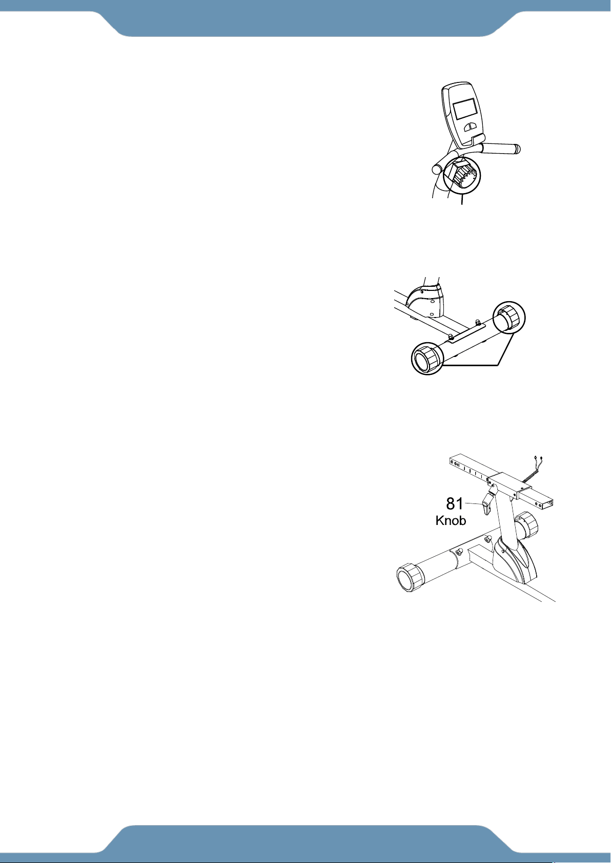
ADJUSTMENTS
Adjusting the Tension Control Knob
To increase the load, turn the Tension Control Knob (14) in a
clockwise direction.
To decrease the load, turn the Tension Control Knob (14) in a
counterclockwise direction.
Rear Stabilizer End Cap (57)
Adjusting the Rear Stabilizer End Cap
Turn the Rear Stabilizer End Caps (57) on the Rear
Stabilizer as needed to level the elliptical trainer
Adjusting the Seat Forward or Back
Turn the Knob (81) in a counter-clockwise direction until the
seat can slide freely. Position the seat to a comfortable
position and lock the seat in place by turning the Knob (81)
clockwise until tightly secured.
NOTE: When adjusting the seat back or forth direction,
make sure the bushing does not exceed the mark line on
the seat sliding tube.
Tension Control Knob (14)

21
MAINTENANCE & TROUBLESHOOTING
MAINTENANCE
Cleaning
The recumbent bike can be cleaned with a soft cloth and mild detergent. Do not use abrasives or
solvents on plastic parts. Wipe your perspiration off the recumbent bike after each use. Be
careful not get excessive moisture on the computer display panel as this might cause an
electrical hazard or electronics to fail. Keep the recumbent bike and console out of direct sunlight
to prevent screen damage.
Please inspect all assembly bolts and pedals on the machine for proper tightness every week.
Storage
Store the recumbent bike in a clean and dry environment away from children.
TROUBLESHOOTING
PROBLEM
SOLUTION
The recumbent bike wobbles when in
use.
Turn the rear stabilizer end cap on the rear
stabilizer as needed to level the recumbent bike.
There is no display on the computer
console.
1. Remove the computer console and verify
the wires that come from the computer
console are properly connected to the wires
that come from the front handlebar post.
2. Check if the batteries are correctly
positioned and battery springs are in proper
contact with batteries.
3. The batteries in the computer console may
be dead. Change to new batteries.
There is no heart rate reading or heart
rate reading or is erratic / inconsistent.
1. Make sure that the wire connections for the
hand pulse sensors are secure.
2. To ensure the pulse readout is more precise,
please always hold on to the handlebar grip
sensors with two hands instead of just with
one hand only when you try to test your
heart rate figures.
3. Gripping the hand pulse sensors too tight.
Try to maintain moderate pressure while
holding onto the hand pulse sensors.
The recumbent bike makes a
squeaking noise when in use.
The bolts may be loose on the recumbent bike,
please inspect the bolts and tighten the loose
bolts.
The console does not connect to the
APP.
1. Reset the console, restart the APP, and try
again. The console is reset by holding the
MODE button for 3-4 seconds.
2. Make sure you are using the
MyCloudFitness APP. There is a MCF Plus
APP that is used with our other health
tracking devices, but MCF Plus does NOT
work with this exercise equipment.
3. Check that your smart device has Bluetooth
powered on. Shut down and restart the APP.

22
WARRANTY
MANUFACTURER’S LIMITED WARRANTY
Paradigm Health & Wellness warrants to the original purchaser that this product is free from
defects in material and workmanship when used for the purpose intended, under the
conditions that it has been installed and operated in accordance with Paradigm’s Owner’s
Manual. Paradigm’s obligation under this warranty applies to the following:
COMPONENT LENGTH OF WARRANTY
Structural Frame 1 year For Home Use Only
All Other Components 90 days For Home Use Only
(computer display, electronics, upholstery, foam, ball bearings, pulleys, belts, cables, wires,
shocks, covers, tension, internal mechanism, wheels, pedals, knobs, accessories and
hardware)
Exclusions from Warranty Coverage:
Paradigm does not warrant against and is not responsible for, and no implied warranty shall be deemed to cover, any
product failure, product malfunction, or damages attributable to:
1. Improper installation and/or failure to abide by Paradigm’s installation guidelines;
2. Use of this product beyond normal home use, or in an application for which it was not designed;
3. Cosmetic items such as scratches, dents or discolorations;
4. Damage caused by normal wear and tear, vandalism, accidental or by animals;
5. Any act of Nature (such as fire, flooding, snow, ice, hurricane, earthquake, lightning or other natural disaster),
environmental condition (such as air pollution, mold, mildew, etc.), or staining from foreign substances (such as dirt,
grease, oil, etc.);
6. Normal weathering due to exposure to sunlight, weather and atmosphere which can cause colored surfaces to,
among other things, flake, chalk, or accumulate dirt or stains; or
7. Improper operation, alteration, handling, storage, abuse or neglect of the products.
Paradigm, using its sole discretion, will either repair or replace free of charge any part(s) proven to
be defective under normal home use. Any repair or replacement shall provide no new warranty
coverage, but shall retain only the remaining portion of the original product’s warranty. This
warranty is offered only to the original purchaser and is not transferable. Proof of original purchase
is required.
Ordering Replacement Parts
Replacement parts can be ordered by emailing our customer service department:
Open Monday thru Friday 8:00 AM - 5:00 PM (PST).
When ordering replacement parts please have the following information ready:
1. Owner’s Manual
2. Model Number
3. Description of Parts
4. Part Number
5. Date of Purchase

23
PARTS REQUEST FORM
Paradigm Health & Wellness, Inc.
EMAIL THIS FORM WITH YOUR RECEIPT OF PURCHASE TO
Service@paradigmhw.com *
NAME:_____________________________________________________________________________________
ADDRESS:__________________________________________________________________________________
CITY:________________________ STATE:_____________ ZIP:_______________________________________
TELEPHONE: (Day)______________________________________________________________________
(Night)_____________________________________________________________________
SERIAL#:___________________________________________________________________________________
MODEL#:___________________________________________________________________________________
PURCHASE DATE:___________________________________________________________________________
PLACE OF PURCHASE:_______________________________________________________________________
“YOUR ORDER WILL BE PROCESSED WITHIN 3 BUSINESS DAYS”
This form can also be faxed to #: 626-810-2166
PART #
DESCRIPTION
QTY


