Loading ...
Loading ...
Loading ...
5
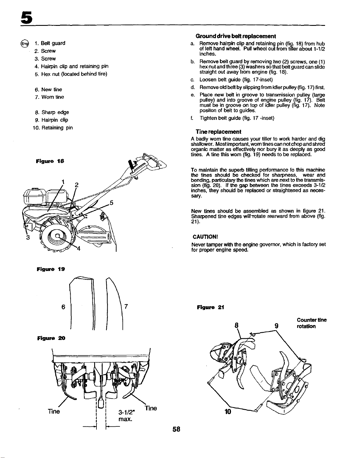
@1. Belt guard
2. Screw
3. Screw
4. Hairpinclipand retainingpin
5. Hex nut(locatedbehindtire)
8. New tine
7. Worn tine
8. Sharp edge
9. Hairpin clip
10. Retaining pin
Figure 11 2
Ground drive belt replacement
a. Remove hairpin clip and retaining pin (fig. 18) from hub
of left hand wheel. Pull wheel out from tillerabout 1-112
inches.
b. Remove belt guard by removing two (2) sorews, one (1)
hex nut and three (3) washers so that belt guard can slide
straight out away from engine (fig. 18).
c. Loosen belt guide (fig. 17-inset)
d. Remove old belt by slippingfrem idler pulley (fig. 17) first.
e. Place new belt in groove to transmission pulley (large
pulley) and into groove of engine pulley (fig. 17). Belt
must be in groove on top of idler pulley (fig. 17). Note
positon of belt to guides.
f. Tighten belt guide (fig. 17 -inset)
Tine replacement
A badly worn tine causes your tiller to work harder and dig
shallower. Most important,worn tinescan not chopand shred
organic matter as effectively nor bury it as deeply as good
tines. A tine this wom (fig. 19) needs to be replaced.
To maintain the superb tilling performance fo this machine
the tines should be checked for sharpness, wear and
bending, particularythe tines which are next to the transmis-
sion (fig. 20). If the gap between the tines exceeds 3-1/2
inches, they should be replaced or straightened as neces-
sary.
New tines should be assembled as shown in figure 21.
Sharpened tine edges will-rotata rearward from above (fig.
21).
CAUTION!
Never tamper with the engine governor, which isfactory set
for proper engine speed.
Figure 19
6
Rgure 20
"Fine
7
i 3-1/2"
I I
I I
,_max.
Tine
58
Figure 21
10
Counter tine
8 9 rotmton
Loading ...
Loading ...
Loading ...