Loading ...
Loading ...
Loading ...
4
5
Inset A
Inset B
10--- _
11---
12_--""
13_
14--""
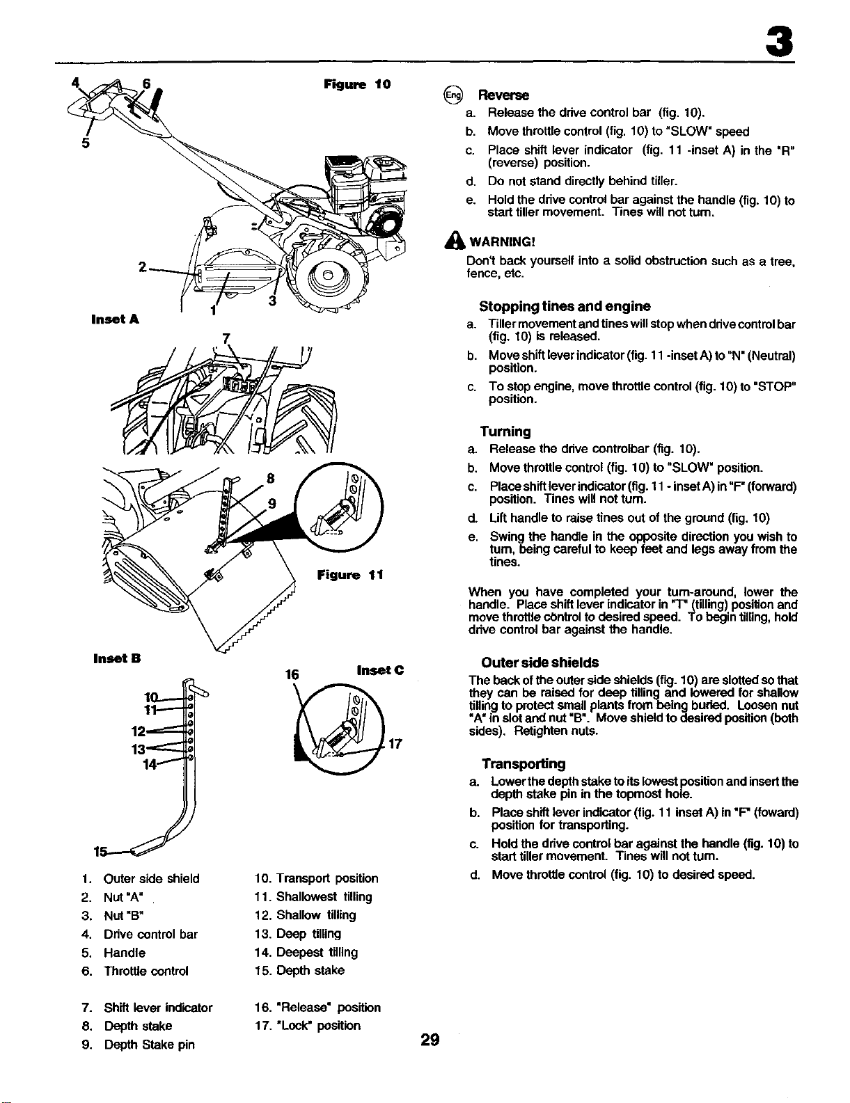
1. Outer side shield
2. Nut"A"
3. Nut"B"
4. Ddve control bar
5. Handle
6. Throttle control
3
7
r_ure t0 GReverse
a. Release the ddve control bar (fig. 10).
b. Move throttle control (fig. 10) to "SLOW" speed
c. Place shift lever indicator (fig. 11 -inset A) in the 'R"
(reverse) position.
d. Do not stand directly behind tiller.
e. Hold the ddve control bar against the handle (fig. 10) to
start tiller movement. Tines will not rum.
_1_ WARNING!
Don't back yourself into asolid obstruction such as atree,
fence, etc.
Stopping tines and engine
a. Tillermovementandtineswillstopwhenddvecontrolbar
(fig. tO) isreleased.
b. Moveshiftloverindicator(fig.11-insetA)to"N"(Neutral)
position.
c. To stopengine,move throttlecontrol (fig.10)to"STOP"
position.
8
Figure 11
Tuming
a. Release the ddve controlbar (fig. 10).
b. Move throttle control (fig. 10) to "SLOW" position.
c. Place shiftlever indicator (fig. 11 - insetA) in "F" (forward)
position. Tines will not turn.
d. Lifthandle to raise tines out of the ground (fig. 10)
e. Swing the handle in the opposite direction you wish to
turn, being careful to keep feet and legs away from the
tines.
When you have completed your turn-around, lower the
handle. Place shift lever indicator in 'T" (tilling)position and
move thrOttlecOntroltodesired speed. To begin tilling,hold
ddve control bar against the handle.
16
10. Transport position
11. Shallowest tilling
12. Shallow tilling
13. Deep tilling
14. Deepest tilling
15. Depth stake
Inset C
17
Outer side shields
The back ofthe outer side shields (fig. 10) are slotted so that
they can be raised for deep tilling and lowered for shallow
tilling to protect small plants from being buried. Loosen nut
"A"in slot and nut "B". Move shield to desired position (both
sides), Rstighten nuts.
Transporting
a. Lower tbe depth stake to its lowest posiUonand insortthe
depth stake pin in the topmost hole.
b. Place shift lever indicator (fig. 11 inset A) in "F" (foward)
position for transporting.
c. Hold the ddve control bar against the handle (fig. 10) to
start tiller movement. Tines will not turn.
d. Move throttle control (fig. tO) to desired speed.
7. Shift lever indicator
8. Depth stake
9. Depth Stake pin
16. "Release" position
17. "Lock" position 29
Loading ...
Loading ...
Loading ...