USER MANUAL
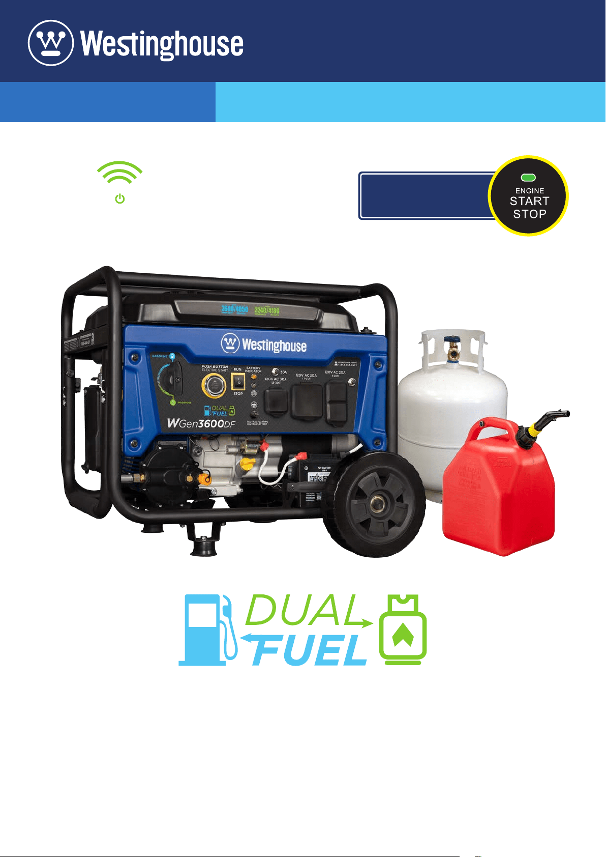
WGen3600DF
Dual Fuel Portable Generator
GASOLINE: 3600 Running Watts | 4650 Peak Watts
PROPANE: 3240 Running Watts | 4180 Peak Watts
REMOTE START
PUSH BUTTON
ELECTRIC START
2 | Westinghouse Portable Power
DISCLAIMERS:
All information, illustrations and specications in this manual are based on the latest information available at
the time of publishing. The illustrations used in this manual are intended as representative reference views only.
Moreover, because of our continuous product improvement policy, we may modify information, illustrations and/or
specications to explain and/or exemplify a product, service or maintenance improvement. We reserve the right
to make any change at any time without notice. Some images may vary depending upon which model is shown.
ALL RIGHTS RESERVED:
No part of this publication may be reproduced or used in any form by any means – graphic, electronic or
mechanical, including photocopying, recording, taping or information storage and retrieval systems – without the
written permission of MWE Investments LLC.
DANGER
This manual contains important instructions for operating this generator. For your safety
and the safety of others, be sure to read this manual thoroughly before operating the
generator. Failure to properly follow all instructions and precautions can cause you and
others to be seriously hurt or killed.
California
Proposition 65 Warning
The engine exhaust from this product
contains chemicals known to the state
of California to cause cancer, birth
defects or other reproductive harm.
California
Proposition 65 Warning
Certain components in this product and its
related accessories contain chemicals
known to the state of California to cause
cancer, birth defects or other reproductive
harm. Wash hands after handling.
Model
Number
Running
Watts
Peak
Watts
Gasoline
Tank Size
(G)
Rated
Speed
(RPM)
Ignition
Type
Spark
plug
Engine
Disp
(cc)
Stroke
X Bore
Oil
Capacity
(L) Oil Type Fuel Type
WGen3600DF Gas:
3600
Propane:
3240
Gas:
4650
Propane:
4180
4 Gallons 3600 TCI F7TC 212cc 55X70 .6 L 10W30 Gasoline
NOTICE
This generator is NOT equipped with altitude carburetor modication. Even with a carburetor modication, engine horsepower will
decrease about 3.5% for each 300 meter (1,000 foot) increase in altitude. The eect of altitude on horsepower will be greater if no
carburetor modication is made. A decrease in engine horsepower will decrease the power output of the generator. Contact our
service team to order altitude kits. See page 16 for altitude kit numbers.
WGen TECHNICAL SPECIFICATIONS
HAVE QUESTIONS?
DO NOT RETURN THIS PRODUCT TO THE STORE
Email us at service@wpowereq.com
or call 1-855-944-3571
SAVE THESE INSTRUCTIONS
Important safety instructions are included in this manual.

Westinghouse Portable Power | 3
FOR YOUR RECORDS:
Date of Purchase:
Generator Model Number:
Purchased from Store/Dealer:
Generator Serial Number:
IMPORTANT: KEEP YOUR PURCHASE RECEIPT TO ENSURE TROUBLE-FREE WARRANTY
COVERAGE.
PRODUCT REGISTRATION
To ensure trouble-free warranty coverage, it is important you register your Westinghouse generator.
You can register your generator by either:
1. Filling in the product registration form below and mailing to:
Product Registration
MWE Investments LLC
777 Manor Park Drive
Columbus, Ohio 43228
2. Registering your product Online at www.westinghouseportablepower.com/register-your-product/
To register your generator you will need to locate the following information:
WESTINGHOUSE PRODUCT REGISTRATION FORM
PERSONAL INFORMATION GENERATOR INFORMATION
First Name: _______________________________________ Model Number: _____________________________________
Last Name: _______________________________________ Serial Number: ______________________________________
Street Address: ___________________________________ Date Purchased: ____________________________________
Street Address: ___________________________________ Purchased From: ____________________________________
City, State, ZIP: ____________________________________
Country: __________________________________________
Phone Number: ___________________________________
E-Mail: ___________________________________________
HAVE QUESTIONS?
DO NOT RETURN THIS PRODUCT TO THE STORE
Email us at service@wpowereq.com
or call 1-855-944-3571
Made in China/
Fabriqu é en Chine
CSA Master Contract
Number :
Numéro de contrat
principa l de CSA
MWE Investments LLC
Columbus Ohio 43228 USA
Con u à columbus , Ohio,tats-Unis
MWE Investments LLC
Columbus Ohio 43228 Etats-Unis
Par t N0.
Numéro de
pièc e
Designed in Columbus , Ohio USA

4 | Westinghouse Portable Power
TABLE OF CONTENTS
WGEN3600DF TECHNICAL SPECIFICATIONS .....2
PRODUCT REGISTRATION
.....................3
For Your Records: ..........................3
Product Registration .......................3
Product Registration Form ...................3
SAFETY
.....................................5
Safety Denitions ..........................5
Safety Symbol Denitions ...................5
General Safety Rules ........................6
Safety Labels and Decals ....................7
Fuel Safety ................................9
UNPACKING
.................................10
What Comes in the Box ......................10
Wheel Kit Accessories Box ...................10
ASSEMBLY
.................................11
Installing Wheels and Feet ....................11
Installing the Battery ........................12
FEATURES
.................................13
Generator Features .........................13
Control Panel Features .....................15
OPERATION
.................................16
Before Starting the Generator .................16
Location Selection .......................16
Grounding the Generator ..................16
High Altitude Operation/Conversion Kits ......16
Power Cord ..............................17
Using Westinghouse Power Cord ...........17
Engine Fluids and Fuel .......................18
Programming Remote Start Key Fob .........18
Adding Gasoline to the Fuel Tank ...........19
Connecting the LPG/Propane Tank ..........19
Switching Fuel Sources ......................20
Starting the Generator ......................21
Starting on Gasoline .....................21
Starting on Propane .....................21
Stopping the Generator ......................22
Normal Operation .......................22
During an Emergency ....................22
MAINTENANCE
..............................23
Maintenance Schedule ......................23
Engine Oil Maintenance .....................24
Engine Oil Specication ...................24
Checking Engine Oil .....................24
Adding Engine Oil .......................24
Changing Engine Oil .....................25
Air Filter Maintenance .......................25
Cleaning the Air Filter ....................25
Spark Plug Maintenance .....................26
Checking and Adjusting Valve Lash ..............27
Cleaning the Generator ......................27
Storage ..................................27
TROUBLE SHOOTING
.........................28
EXPLODED AND ENGINE VIEWS
................30
WGen3600DF Exploded View .................30
WGen3600DF Engine View ...................32
SCHEMATICS
................................33
WGen3600DF Schematic ....................33
Westinghouse Portable Power | 5
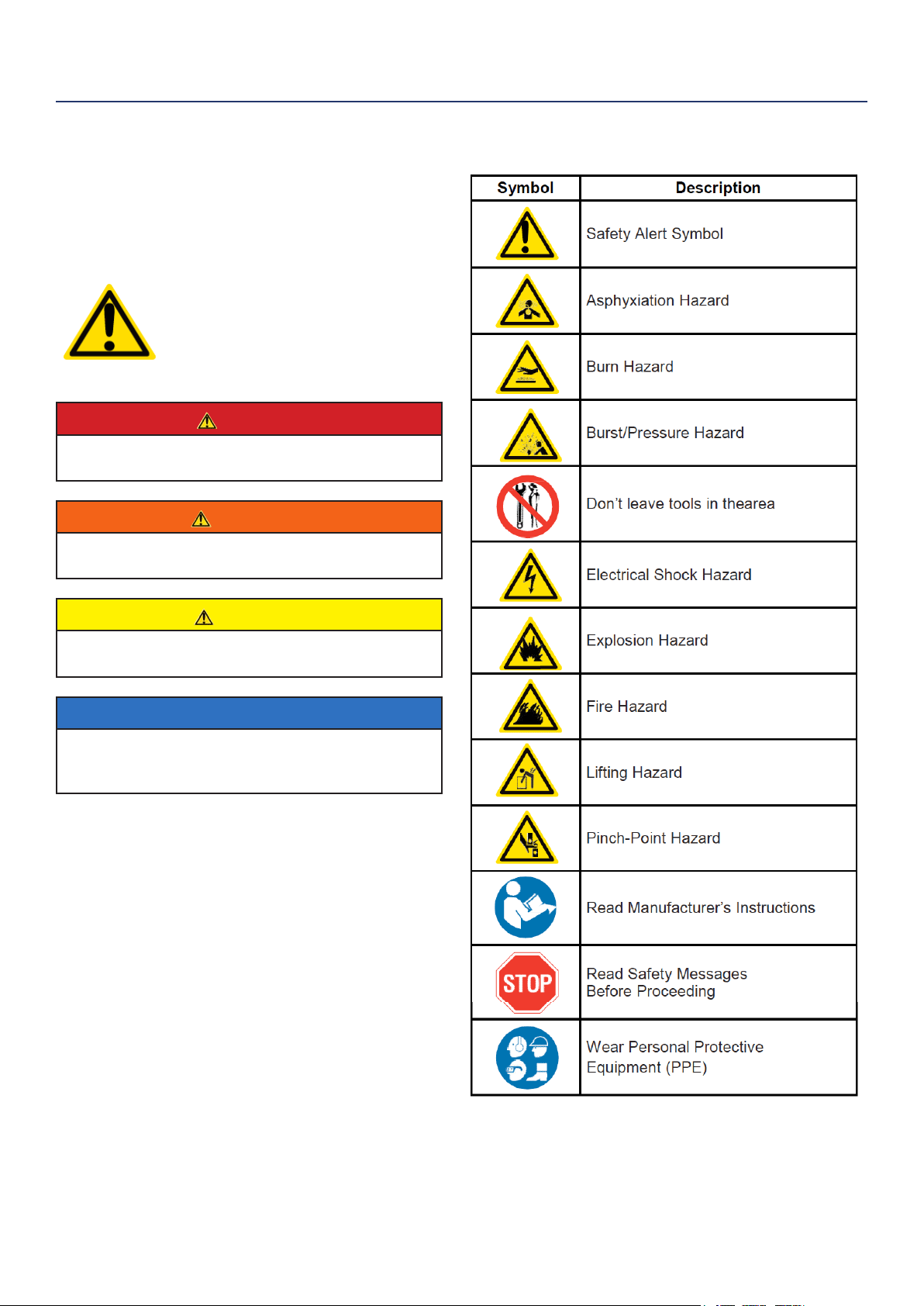
SAFETY DEFINITIONS
The words DANGER, WARNING, CAUTION and
NOTICE are used throughout this manual to highlight
important information. Be certain that the meanings of
these alerts are known to all who work on or near the
equipment.
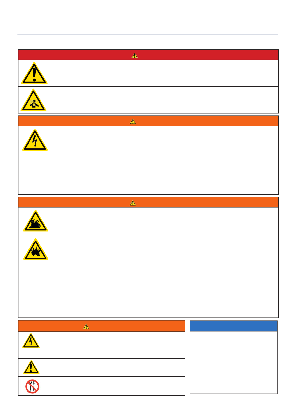
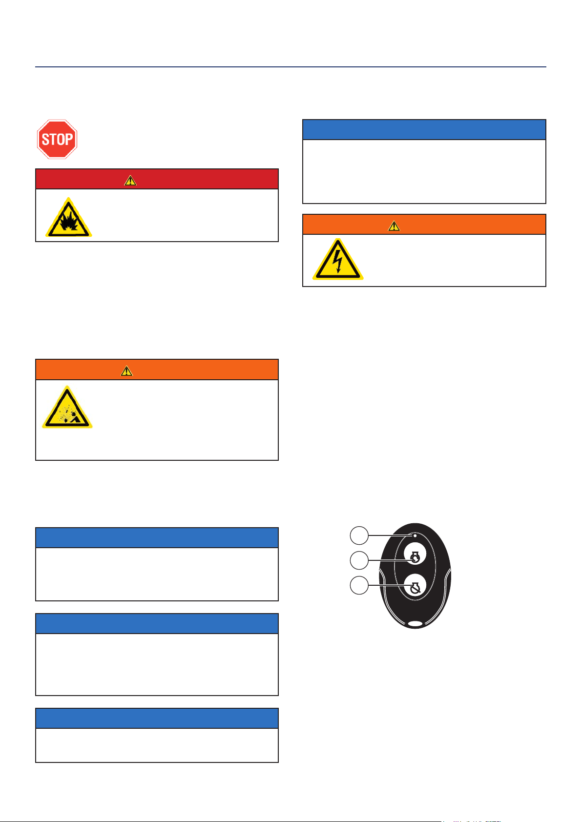
This safety alert symbol appears
with most safety statements. It
means attention, become alert, your
safety is involved! Please read and
abide by the message that follows
the safety alerts symbol.
DANGER
Indicates a hazardous situation which, if not
avoided, will result in death or serious injury.
WARNING
Indicates a hazardous situation which, if not
avoided, could result in death or serious injury.
CAUTION
Indicates a hazardous situation which, if not
avoided, could result in minor or moderate injury.
NOTICE
Indicates a situation which can cause damage to the
generator, personal property and/or the environment,
or cause the equipment to operate improperly.
NOTE: Indicates a procedure, practice or condition
that should be followed in order for the
generator to function in the manner
intended.
SAFETY
SAFETY SYMBOL DEFINITIONS
6 | Westinghouse Portable Power
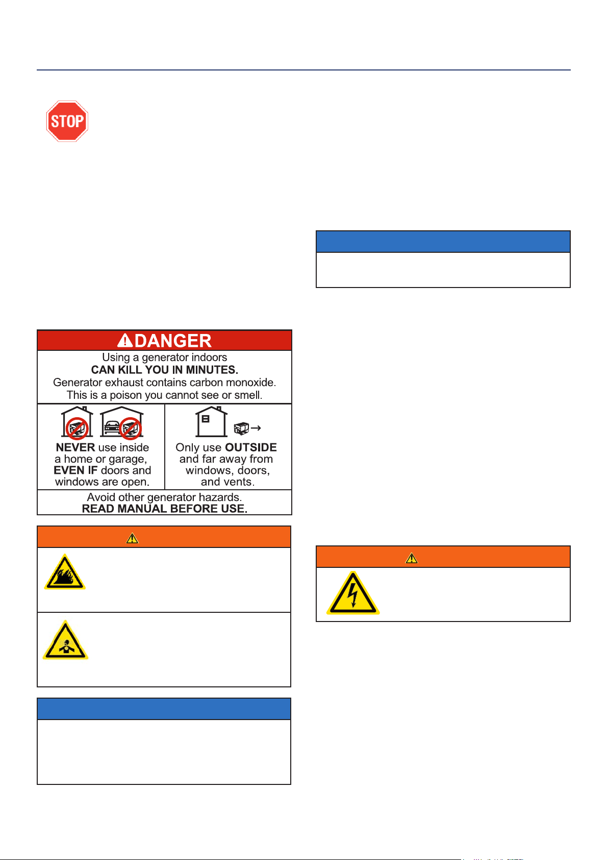
DANGER
Never use the generator in a location that is wet or damp. Never expose the generator to rain,
snow, water spray or standing water while in use. Protect the generator from all hazardous weather
conditions. Moisture or ice can cause a short circuit or other malfunction in the electrical circuit.
Never operate the generator in an enclosed area. Engine exhaust contains carbon monoxide. Only
operate the generator outside and away from windows, doors and vents.
WARNING
Voltage produced by the generator could result in death or serious injury.
• Never operate the generator in rain or a ood plain unless proper precautions are taken to avoid
being subject to rain or a ood.
• Never use worn or damaged extension cords.
• Always have a licensed electrician connect the generator to the utility circuit.
• Never touch an operating generator if the generator is wet or if you have wet hands.
• Never operate the generator in highly conductive areas such as around metal decking or steel
works.
• Always use grounded extension cords. Always use three-wire or double-insulated power tools.
• Never touch live terminals or bare wires while the generator is operating.
• Be sure the generator is properly grounded before operating.
WARNING
Gasoline, gasoline vapors & liquid petroleum gas (LPG) are extremely ammable and explosive
under certain conditions.
• Always refuel the generator outdoors, in a well-ventilated area.
• Never remove the fuel cap with the engine running.
• Never refuel the generator while the engine is running. Always turn engine o and allow the
generator to cool before refueling.
• Only ll fuel tank with gasoline.
• Keep sparks, open ames or other form of ignition (such as matches, cigarettes, static electric
sources) away when refueling.
• Never overll the fuel tank. Leave room for fuel to expand. Overlling the fuel tank can result in a
sudden overow of gasoline and result in spilled gasoline coming in contact with HOT surfaces.
Spilled fuel can ignite. If fuel is spilled on the generator, wipe up any spills immediately. Dispose
of rag properly. Allow area of spilled fuel to dry before operating the generator.
• Wear eye protection while refueling.
• Never use gasoline as a cleaning agent.
• Store any containers containing gasoline or propane in a well-ventilated area, away from any
combustibles or source of ignition.
• Check for fuel leaks after refueling. Never operate the engine if a fuel leak is discovered.
WARNING
Never operate the generator if powered items overheat,
electrical output drops, there is sparking, ames or smoke
coming from the generator, or if the receptacles are
damaged.
Never use the generator to power medical support
equipment.
Always remove any tools or other service equipment used
during maintenance from the generator before operating.
NOTICE
Never modify the generator.
Never operate the generator if it
vibrates at high levels, if engine
speed changes greatly or if the
engine misres often.
Always disconnect tools or
appliances from the
generator before starting.
GENERAL SAFETY RULES
SAFETY
Westinghouse Portable Power | 7
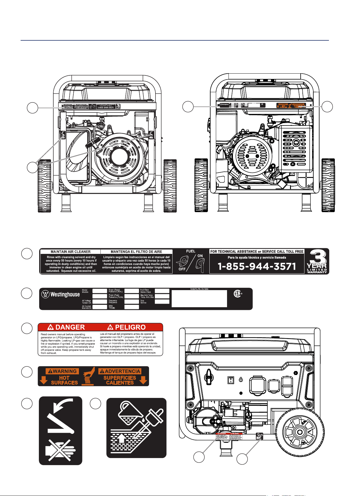
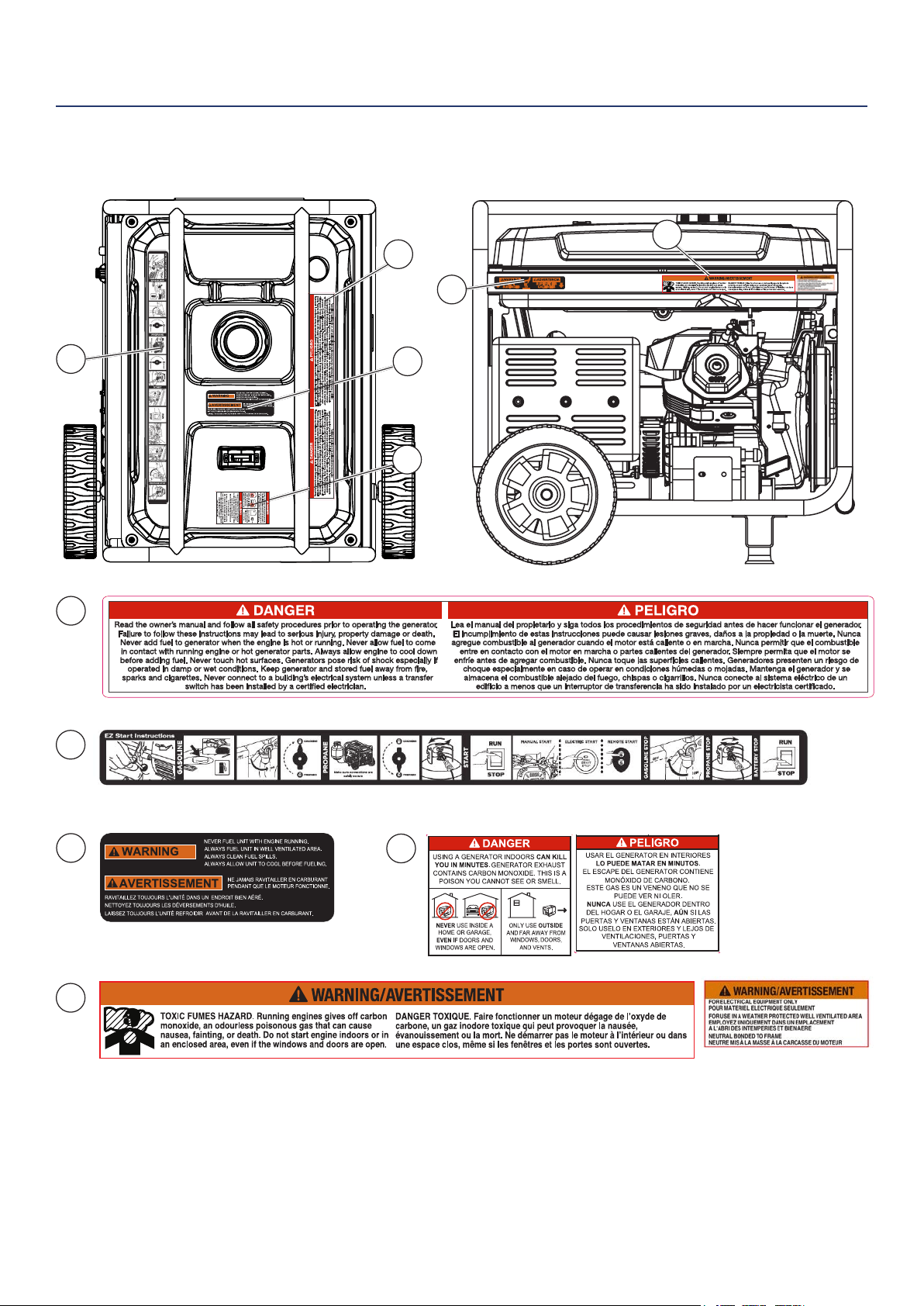
SAFETY
SAFETY LABELS AND DECALS
4
1
3
6
2
4
1
5
Made in China/
Fabriqu é en Chine
CSA Master Contract
Number :
Numéro de contrat
principa l de CSA
MWE Investments LLC
Columbus Ohio 43228 USA
Con u à columbus , Oh io,tats-Unis
MWE Investments LLC
Columbus Ohio 43228 Etats-Unis
Part N0.
Numéro de
pièce
Designed in Columbus , Ohio USA
Made in China/ Fabriqu é en Chine
CSA Master Contract
Number :
Numéro de contrat
principa l de CSA
MWE Investments LLC
Columbus Ohio 43228 USA
Con u à columbus , O hio,tats-Unis
MWE Investments LLC
Columbus Ohio 43228 Etats-Unis
Par t N0.
Numéro de
pièc e
Designed in Columbus , Ohio USA
2 4
5
3
6
8 | Westinghouse Portable Power
SAFETY
SAFETY LABELS AND DECALS
9
10
8
11
9
10
7
7
4
11
8
Westinghouse Portable Power | 9
When transporting or servicing the generator:
• Make certain the fuel shuto valve is o and the fuel
tank is empty.
• Make sure the LPG tank and LPG hose is not attached
to the generator.
• Disconnect the spark plug wire.
When storing the generator:
• Store away from sparks, open ames, pilot lights, heat
and other sources of ignition.
• Do not store gas or LPG tank near furnaces, water
heaters or any other appliances that produce heat or
have automatic ignitions.
CAUTION
Only use approved LPG tanks with
OPD (overlling prevention device)
valve. Always keep the tank in a
vertical position with the valve on
top and installed at ground level on a
at surface. Do not allow tanks to be
around any heat source and make sure
it is not exposed to the sun, rain and
dust. When transporting and storing,
turn o the tank valve and fuel valve,
and disconnect the tank. Make sure to
always cover the generator and tank
outlet with protective plastic caps.
CAUTION
Do not allow children to tamper or
play with the propane tank or hose
connections.
WARNING
If there is a strong smell of propane
while operating the generator close the
valve on the propane tank immediately.
Once the propane is o, use soapy
water to check for leaks on the hose
and connections on the tank valve and
the generator. Do not smoke or light a
cigarette or check for leaks using any
open ame source such as a match
or lighter. If a leak is found contact
a qualied technician to inspect and
repair the LPG system before using the
generator.
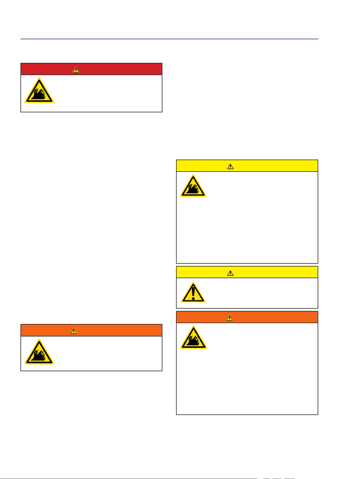
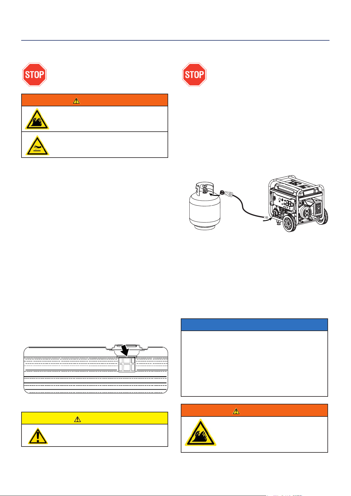
DANGER
Gasoline and liquid petroleum gas
(LPG) are highly explosive and
ammable. Explosions and re can
cause severe burns or death.
Gasoline and gasoline vapor (Gas)
• Gasoline is highly ammable and explosive.
• Gas expands and contracts with dierent
temperatures.
• In case of a gas re, do not attempt to extinguish the
ame if the fuel shuto valve is in the on position.
Introducing an extinguisher to a generator with an
open fuel valve could create an explosion hazard.
• Gas has a distinctive odor, this will help detect
potential leaks quickly.
• Gas vapors can cause a re if ignited.
• Gasoline is a skin irritant and needs to be cleaned up
immediately if it comes in contact with the skin.
Liquid Petroleum Gas (Propane/LPG)
• LPG/Propane is highly ammable and explosive.
• Flammable gas under pressure can cause a re or
explosion if ignited.
• LPG/Propane can settle in low places because it is
heavier than air.
• LPG/Propane has a distinctive odor added to help
detect potential leaks.
• Always keep LPG/Propane tank in an upright position.
• When exchanging LPG/Propane tanks, be sure the
tank value is the same type.
• In case of a LPG/Propane re, do not attempt to
extinguish unless the fuel supply can be shut o.
• LPG/Propane will burn the skin. Prevent skin contact
at all times.
WARNING
Never use a gas container, LPG
connector hose, LPG tank or any
other fuel item that appears to be
damaged.
When starting generator:
• Make sure that the gas cap, air lter, spark plug, fuel
lines and exhaust system are properly in place.
• If you spill any gasoline on the tank, allow it to fully
evaporate before operating.
• Make sure the generator and propane tank are on a
at surface before operating.
• If there is a propane odor do not start the unit because
there may be a potential leak.
• Never place propane tank near engine exhaust.
SAFETY
FUEL SAFETY
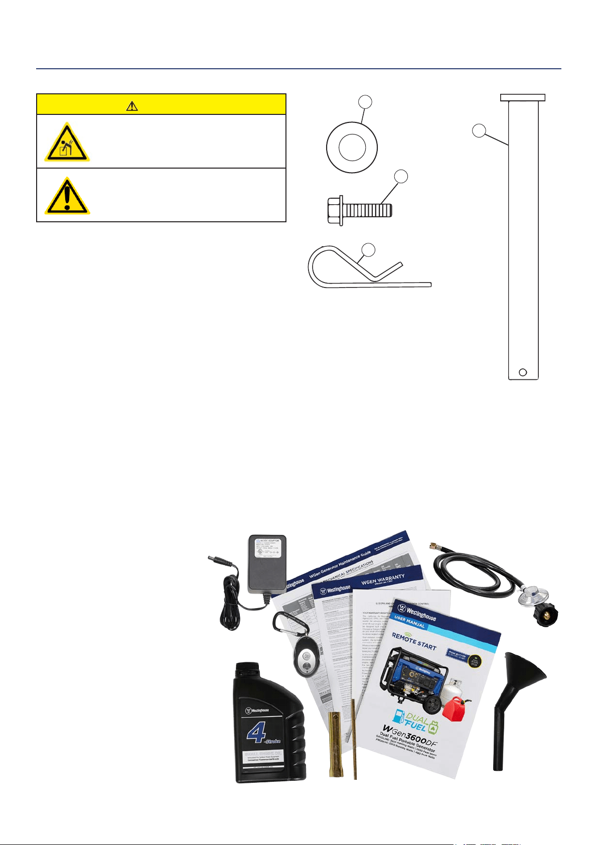
10 | Westinghouse Portable Power
1. Washer (2 used)
2. Flange Bolt M8 x16mm (4 used)
3. Hairpin Cotter Pin (2 used)
4. Wheel Axle Pin (2)
CAUTION
Always have assistance when lifting
the generator. The generator is heavy;
lifting it could cause bodily harm.
Avoid cutting on or near staples
to prevent personal injury.
Tools required – box cutter or similar device.
1. Carefully cut the packing tape on top of the carton.
2. Fold back top aps to reveal the manual.
3. Remove the Wheel Kit Accessories cardboard box.
4. Carefully cut two sides of the carton to
remove the generator.
WHAT COMES IN THE BOX
Owners Manual
Quick Start Guide/Maintenance Schedule
Remote Start Key Fob (1)
Battery Charger (1)
LPG Hose (1)
.6 Liter Bottle of SAE 10W30 Oil (1)
Spark Plug Socket Wrench (1)
Wheel Kit Accessories Box
Funnel (1)
WHEEL KIT ACCESSORIES BOX
Open the Wheel Kit Accessories box and verify the
contents against the list right. If any parts are missing,
contact our service team at [email protected] or
call 1-855-944-3571.
UNPACKING
Figure 1 -Wheel and Feet Kit Hardware
1
2
3
4
Westinghouse Portable Power | 11
INSTALLING WHEELS AND FEET
BEFORE ASSEMBLING THE
GENERATOR, REVIEW THE SAFETY
SECTION STARTING ON PAGE 5.
CAUTION
Never lift the generator without
assistance. The generator is heavy
and lifting without assistance could
result in personal injury.
Never use the handles as a lifting point
to support the entire weight of the
generator. Only use the handles to move
the generator by lifting the handles and
using the wheels to move the generator.
Use caution when collapsing the
handles. Hands and ngers could get
caught and pinched.
NOTICE
Assembling the generator will require lifting the unit
on one side. Make sure all engine oil and fuel are
drained from the unit prior to assembling. Once
assembled, the wheel kit is not intended for on-
road use. The wheel kit is designed for use on this
generator only.
INSTALLING FEET TO FRAME
1. Place generator on a at surface.
2. Place a piece of cardboard or other soft material to
tip the generator onto, to protect the frame paint
and prevent the generator from sliding. Tip the
generator onto the side.
3. Install the mounting foot to the frame using M8
ange bolts.
1 - Mounting Feet
2 - Flange Bolts M8
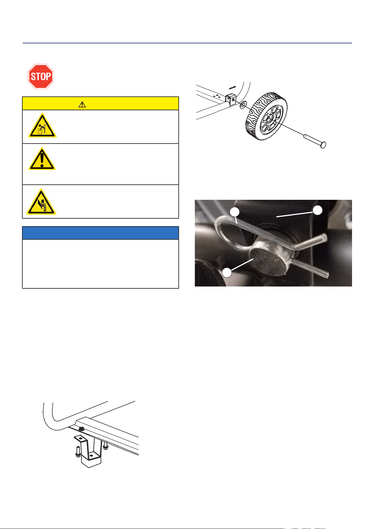
INSTALLING WHEELS TO FRAME
1. Insert axle pin through washer and wheel.
2. Install the wheel with axle pin through the axle
bracket on the frame. The eye of the bolt should be
facing toward the inside of the generator.
2
1
3
Figure 3 - Assemble Wheel to Frame
3. Install the hairpin cotter through the axle pin to lock
it in place.
1 - Axle Bracket
2 - Hairpin Clip
3 - Axle Pin
4. Repeat previous steps on other wheel.
ASSEMBLY
Figure 2 -Wheel Assembly
Figure 1 - Assemble Mounting Feet to Frame
12 | Westinghouse Portable Power
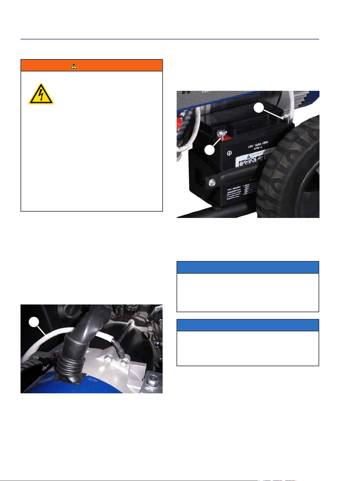
4. Pull back the black boot and securely attach
the negative (-) battery cable (black boot) to the
negative (-) battery post as shown in Figure 5.
Replace the black boot so it protects the cable lug
and battery post.
1 - Positive (+) Battery Cable (Red)
2- Negative (-) Battery Cable (Black)
NOTICE
The electric start generator is equipped with a battery
charging feature. Once the engine is running, a small
charge is supplied to the battery via the battery
cables and will slowly recharge the battery.
NOTICE
Even if you do not plan on using the electric start
feature it is recommended that you install the battery
to complete the circuit in order for the automatic
choke mechanism to work properly.
INSTALLING THE BATTERY
WARNING
To avoid electric shock:
• ALWAYS connect the positive (+)
battery cable (red boot) rst when
connecting battery cables.
• ALWAYS disconnect the negative (-)
battery cable (black boot) rst when
disconnecting battery cables.
• NEVER connect the negative (-)
battery cable (black boot) to the
positive (+) post on the battery.
• NEVER connect the positive (+)
battery cable (red boot) to the
negative (-) post on the battery.
• NEVER touch both battery posts
simultaneously.
• NEVER place a metal tool across
both battery posts.
• ALWAYS use insulated or
nonconducting tools when installing
the battery.
1. Secure the positive (+) battery cable (red boot)
tightly to the positive (+) battery post. Make sure
boot is over battery post.
2. Carefully remove the protective wrapping around
the lug of the negative (-) battery cable (black boot).
3. Locate negative (-) cable attached to alternator
cable, remove tie and route to the negative (-)
battery post. See gure 4 below for location of
negative (-) cable.
ASSEMBLY
Figure 4 - (1) Negative Cable
Figure 5 - Attaching the Negative (-) Battery Wire (black)
1
1
2
Westinghouse Portable Power | 13
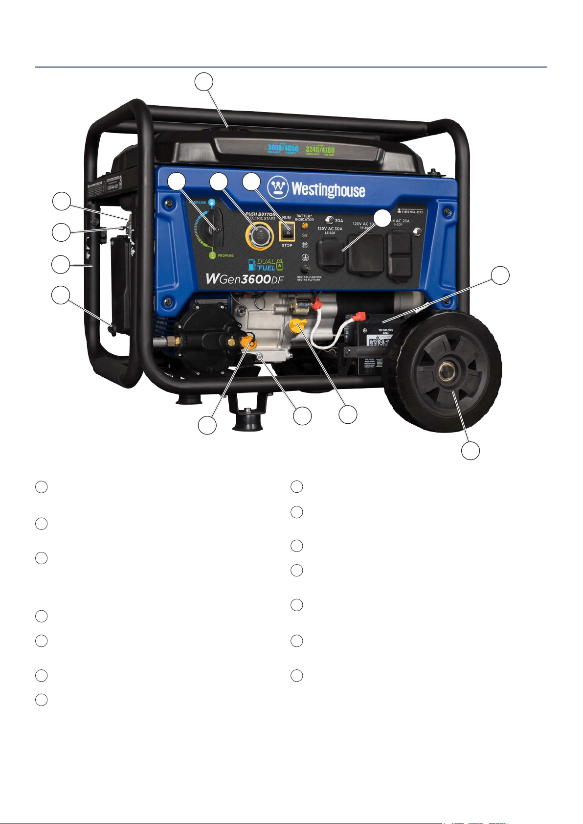
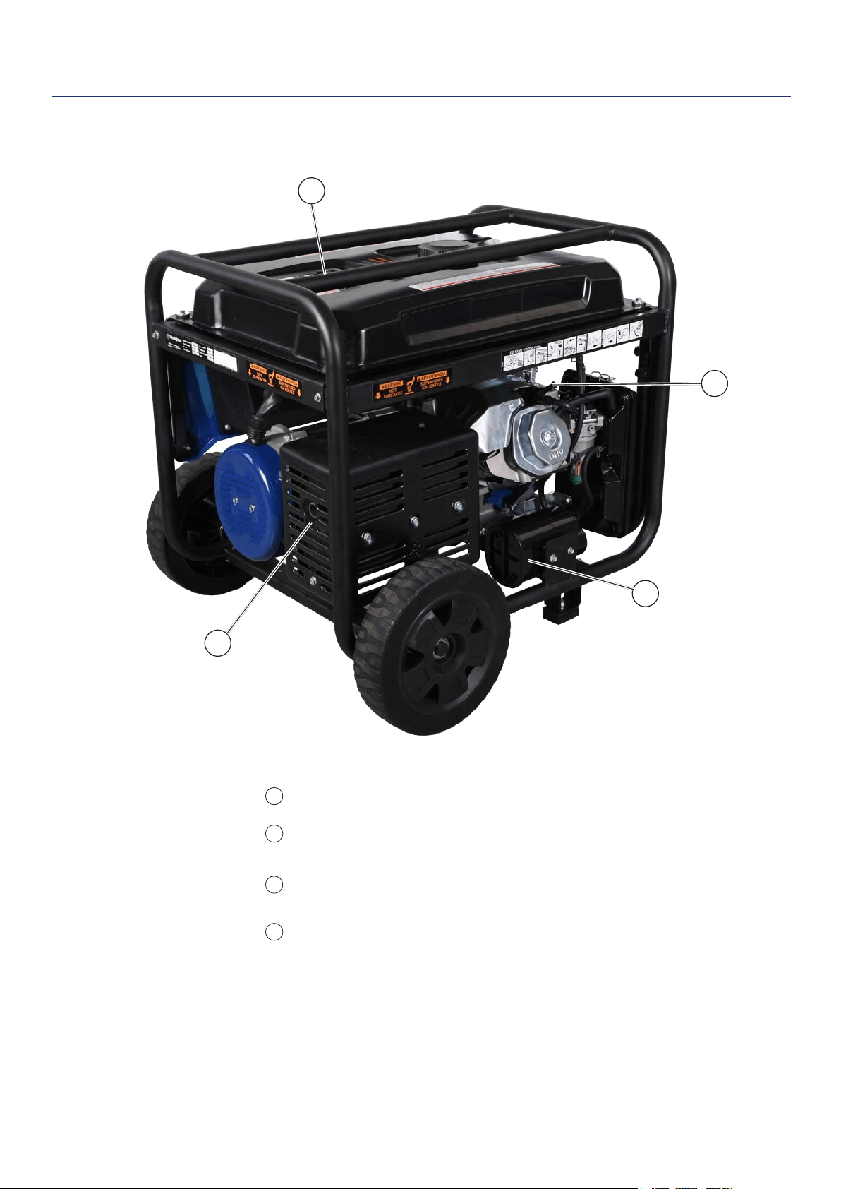
Fuel Selector Switch: Used to select and turn
on gasoline or propane fuel source.
Push Button Electric Start: Starts and stops
the engine.
Engine Control Switch/Battery Disconnect:
Allows fuel to ow to engine and energizes
the ignition system. Also, disconnects battery
power when in STOP position.
Fuel Cap: Close until clicking sound is heard.
Control Panel: Contains the circuit breakers
and outlets.
Battery: Included for electric start models.
Oil Fill Plug/Dipstick: Must be removed to add
and check oil.
FEATURES
Oil Drain Plug: Must be removed to drain engine oil.
Propane Hook Up: Hook up your propane tank with
the LPG hose provided to this inlet.
Never Flat Wheels: For easy portability.
Auto Choke: Automatically sets the engine choke
when starting engine.
Gas Fuel Shut O Valve: Controls the ow of gas
to the engine.
Single Piece Handle: Includes rubber grip. Allows
you to easily push or pull unit with one hand.
Air Filter: Rotate knob to unlock air cleaner cover for
easy access.
1
5
6
7
8
10
9
11
12
13
14
2
3
4
1
2 3
5
7
8
10
11
9
13
14
6
12
4
14 | Westinghouse Portable Power
Fuel Gauge: Indicates gas level.
Spark Plug Boot (Wire): Must be removed
when servicing the engine or the spark plug.
CARB Canister: Required for models sold into
and used in California.
Muer and Spark Arrester: Avoid contact
until engine is cooled down. Spark arrestor
prevents sparks from exiting the muer. It must
be removed for servicing.
FEATURES
1
2
3
4
1
2
3
4
Westinghouse Portable Power | 15
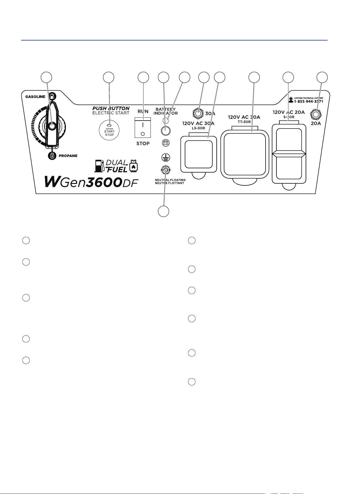
30-Amp Circuit Breaker: Circuit breaker limits
the current that can be delivered through the 120-
volt outlet to 30amps.
120-Volt, 30 Amp Twistlock Outlet (L5-30R):
Outlet can supply 120V output.
120-Volt 30 Amp Outlet (TT-30R): Travel Trailer
outlet can supply a maximum of 30 amps and 120
volts.
120-Volt, 20-Amp Duplex Outlets (5-20R): Each
outlet is capable of carrying a maximum of 20
amps on a single receptacle or a combination of
both receptacles.
20-Amp Circuit Breaker: Circuit breaker limits
the current that can be delivered through the 120-
volt duplex outlets to 20amps.
Ground Terminal: The ground terminal is used to
ground the generator.
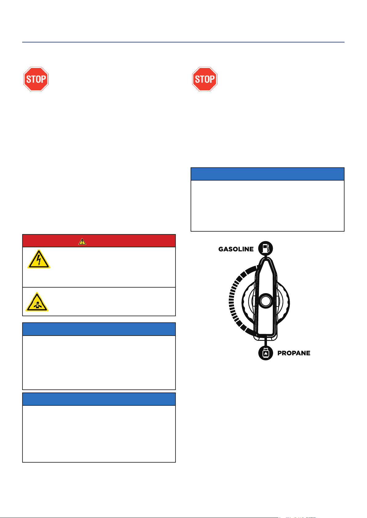
Fuel Selector Switch: Select and turn on gas or
propane.
Push Start Button:
• Push for 1 second to automatically start the
engine. Green light shows when unit is on.
• Push again to stop the engine.
Engine Control Switch/Battery Disconnect:
Switch to STOP to stop the engine. When in
STOP position it prevents the unit from drawing
power from the battery. Switch to RUN before
starting engine.
Battery Charge Port: Used to charge the battery
when the unit is o (battery charger included).
Battery Indicator Light: When light is illuminated,
the battery is connected.
CONTROL PANEL FEATURES
1
8
9
10
11
2
3
4
5
6
7
3 4 5 6 87 9 1021
11
FEATURES
16 | Westinghouse Portable Power
Weather – Never operate your generator outdoors during
rain, snow or any combination of weather conditions that
could lead to moisture collecting on, in or around the
generator.
Dry Surface – Always operate the generator on a dry
surface free of any moisture.
No Connected Loads – Make sure the generator has no
connected loads before starting it. To ensure there are no
connected loads, unplug any electrical extension cords
that are plugged into the control panel receptacles.
NOTICE
Starting the generator with loads already applied to it could result
in damage to any appliance being powered o the generator during
the brief start-up period.
Grounding the Generator – The National Electric Code
(NEC), as well as many local electrical codes, may require
the generator to be connected to earth ground. The
most common application that requires a ground rod is
when you are using the generator as a separately derived
system to provide back up power to your house. Typically
this is when a transfer switch has a switched neutral.
As the generator application has many variables that
cannot be determined by the manufacturer of the
generator, a licensed electrician will need to determine if a
grounding rod is needed.
If a licensed electrician has determined the application
requires a ground rod, make sure it is connected to earth
ground by connecting the ground terminal on the control
panel to earth ground using copper wire (minimum 10
AWG). Consult a qualied electrician for local grounding
requirements.
WARNING
Be sure the generator is properly connected to
earth ground before operating. The generator
must be grounded to prevent electrical shock
due to faulty appliances.
High Altitude Operation
Engine power is reduced the higher you operate above
sea level. Output will be reduced approximately 3.5%
for every 1000ft of increased altitude from sea level.
This is a natural occurrence and cannot be adjusted by
engine. Increased exhaust emissions can also result
due to increased fuel mixture. Other issues include hard
starting, increased fuel consumption and spark plug
fouling. Contact our service team 1-855-944-3571 for
altitude part kits.
High Altitude Carburetor Kit Part Number: 140543
High Altitude DF Regulator Part Number: 140560
Note: You must purchase the Dual Fuel Regulator along with carburetor kit on
the WGen3600DF
BEFORE STARTING THE GENERATOR
BEFORE STARTING THE GENERATOR,
REVIEW SAFETY SECTION STARTING
ON PAGE 5.
Location Selection – Before starting the generator,
avoid exhaust and location hazards by verifying:
• You have selected a location to operate the generator
that is outdoors and well ventilated.
• You have selected a location with a level and solid
surface on which to place the generator.
• You have selected a location that is at least 6 feet
(1.8 m) away from any building, other equipment or
combustible material.
• If the generator is located close to a building, make
sure it is not located near any windows, doors and/
or vents.
WARNING
Always operate the generator on a level surface.
Placing the generator on non level surfaces can
cause the generator to tip over, causing fuel and
oil to spill. Spilled fuel can ignite if it comes in
contact with an ignition source such as a very hot
surface.
Do not operate a device plugged into the USB
ports. Prolonged exposure to engine exhaust can
cause serious injury or death. While charging a
device do not place on the exhaust side of the
generator. Extreme heat caused by exhaust can
damage the device, and cause a potential re
hazard.
NOTICE
Only operate the generator on a solid, level surface. Operating the
generator on a surface with loose material such as sand or grass
clippings can cause debris to be ingested by the generator that
could:
• Block cooling vents
• Block air intake system
OPERATION
Westinghouse Portable Power | 17
POWERCORD
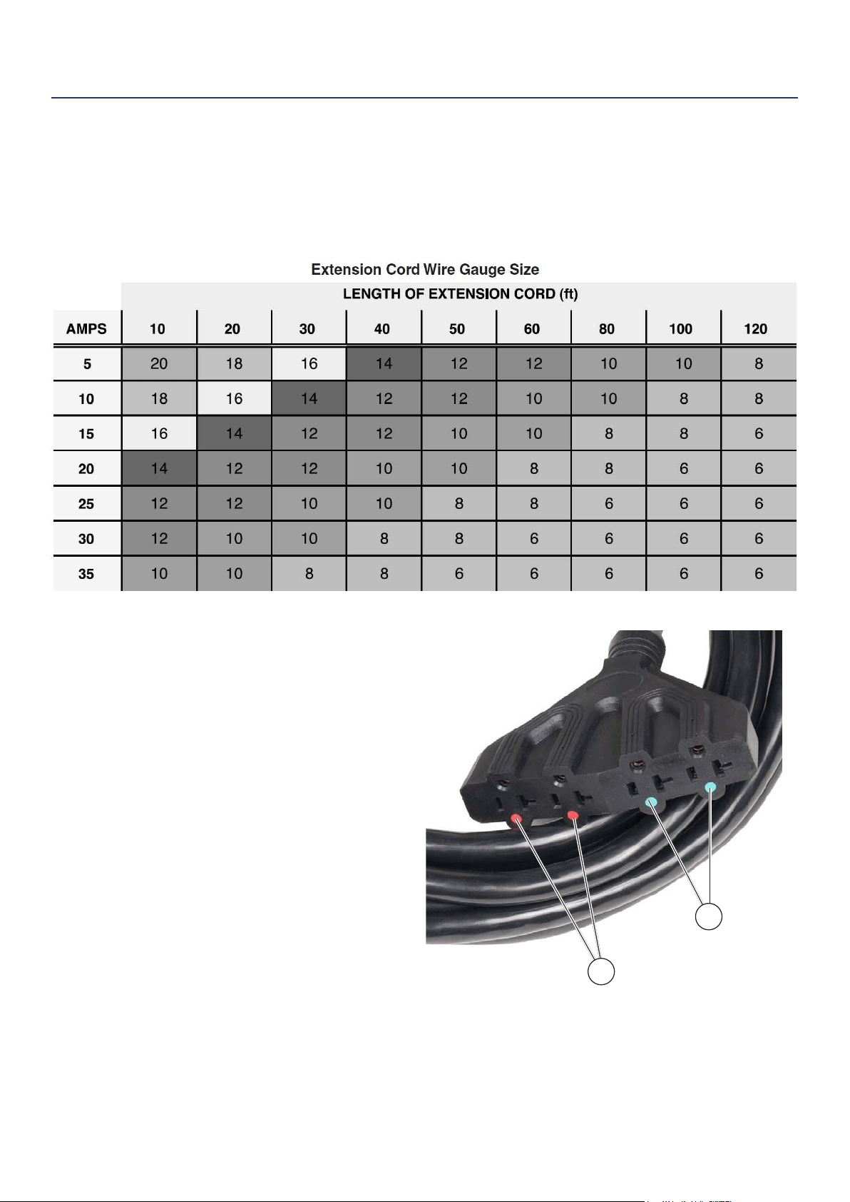
Using Extension Cords
Westinghouse Portable Power assumes no responsibility for the content within this table. The use of this table is the
responsibility of the user only. This table is intended for reference only. The results produced by using this table are
not guaranteed to be correct or applicable in all situations as the type and construction of cords are highly variable.
Always check with local regulations and a licensed electrician prior to installing or connecting an electrical appliance
Using Westinghouse Power Cord
Use the extension cord chart to determine the size
of the conductor for extension cord applications.
Determine the distance of the generator to the
appliance on the top line of the chart. Then select the
rated amperage of the generator on the left side of the
chart. Where the two meet is the size of the conductor
required for the application.
The WCG25 power cord is connected to the generator
at the 120/240 plug. The opposite end of the power
cord is a fan tail receptacle with 2 green receptacles
and 2 red receptacles. Each receptacle is rated at
120 volts AC. To balance the load on the generator’s
alternator, use the red and green identiers on the fan
tail receptacle. To keep the load balanced, connect
the loads so that both color receptacles are used. An
example is one in red and one in green. Do not connect
2 in red and none in green, or 2 in green and none in
red. If only one color receptacle is used with multiple
loads, the alternator may experience an unbalanced
load, causing undue vibration to generator.
OPERATION
1
2
Figure 6 - WCG25 Extension Cord
Red Dots
Green Dots
18 | Westinghouse Portable Power
ADDING / CHECKING ENGINE
FLUIDS AND FUEL
BEFORE ADDING/CHECKING ENGINE
FLUIDS AND FUEL, REVIEW SAFETY
SECTION STARTING ON PAGE 5.
DANGER
Filling the fuel tank with gasoline while the
generator is running can cause gasoline to leak
and come in contact with hot surfaces that can
ignite the gasoline.
Before starting the generator, always check:
• Level of Engine oil
• Level of gasoline in the fuel tank
• Secured connection to an undamaged LPG tank
It is not safe to add gasoline to the fuel tank or engine
oil to the engine while the engine is running or the
engine and muer are hot.
CHECKING AND / OR ADDING ENGINE OIL
WARNING
Internal pressure can build in the engine
crankcase while the engine is running.
Removing the oil ll plug/ dipstick while the
engine is hot can cause extremely hot oil to
spray out of the crankcase and can severely
burn skin. Allow engine oil to cool for several
minutes before removing the oil ll plug/
dipstick.
The unit as shipped does not contain oil in the engine.
You must add engine oil before starting the generator
for the rst time. See Checking Engine Oil and Adding
Engine Oil on page 24 for instructions on checking
engine oil level and the procedure for adding engine oil.
NOTICE
The engine does not contain engine oil as shipped.
Attempting to start the engine can damage engine components.
The owner of the generator is responsible to ensure the proper oil
level is maintained during the operation of the generator. Failure to
maintain the proper oil level can result in engine damage.
NOTICE
During the rst ve hours of operating the generator make sure to
not exceed 50% of the rated running watts until the unit is broken
in properly. Make sure to vary to load occasionally to allow stator
windings to heat and cool. Adjusting the load will also help seat
piston rings. Check oil more often during the rst couple times of
operating the generator.
NOTICE
Weather will aect engine oil performance. Change the type of
engine oil used based on weather conditions to suit the engine
needs.
OPERATION
PROGRAMMING THE GENERATOR FOR
REMOTE START
NOTICE
The key fob included with the generator should come
already paired with the unit. If it does not you can
follow the directions below to reconnect. If your unit
was shipped without a key fob please contact our
customer support team.
WARNING
Always make sure the area around
the generator is clear of bystanders
before using the remote start to start
the generator.
The generator can be started remotely from up to a
maximum of 109 yards (100 M) away using the remote
start key fob with new, fully charged batteries in the
key fob. As the batteries’ state of charge in the key fob
reduces, the distance to start the generator will also
reduce.
Before the generator can be started, an initial start-up
procedure must be performed so the generator and the
key fob recognize each other. If the key fob is replaced,
you will need to go through this procedure with the new
fob.
1. Turn the engine control switch to the RUN position.
2. Push and hold the red REMOTE PAIRING button
on the side of the control panel for 3 seconds.
3. Press and hold the STOP button on the remote
start key fob, the indicator light (see 1 below) at the
top of the remote will icker once.
Remote Start Key Fob
1 - Pairing Indicator light
2 - Start Button | 3 - Stop Button
4. Press and hold the START button on the remote
start key fob, the indicator light at the top of the
remote will icker once.
5. Press and hold the REMOTE PAIRING button for
3 seconds. The generator is now programmed to
start remotely
START
STOP
1
2
3
Westinghouse Portable Power | 19
ADDING GASOLINE TO THE FUEL TANK
BEFORE ADDING GAS TO THE TANK
PLEASE REVIEW FUEL SAFETY
SECTION ON PAGE 9
WARNING
Never refuel the generator while the engine is
running.
Always turn the engine o and allow
the generator to cool before refueling.
Required Gasoline – Only use gasoline that meets the
following requirements:
• Unleaded gasoline only
• Gasoline with maximum 10% ethanol added
• Gasoline with an 87 octane rating or higher
Filling the Fuel Tank – Follow the steps below to ll the
fuel tank:
1. Shut o the generator.
2. Allow the generator to cool down so all surface
areas of the muer and engine are cool to the
touch.
3. Move the generator to a at surface.
4. Clean area around the fuel cap.
5. Remove the fuel cap by rotating counterclockwise.
6. Slowly add gasoline into the fuel tank. Be very
careful not to overll the tank. The gasoline level
should NOT be higher than the ller neck (see
Figure 7).
7. Install the fuel cap by rotating clockwise until
you hear a click, indicating the cap is completely
installed.
CAUTION
Avoid prolonged breathing of gasoline vapors.
OPERATION
Figure 7 - Maximum Gasoline Fill Level
CONNECTING THE LPG/PROPANE TANK
BEFORE CONNECTING PROPANE TANK
TO THE GENERATOR PLEASE REVIEW
FUEL SAFETY SECTION ON PAGE 9
Connecting LPG Tank
1. Make sure the generator is o, on a at surface in
well ventilated area.
2. Make sure propane tank valve is in the o position.
3. Make sure the fuel selector switch on the generator
control panel is pointing downward to “Propane”.
4. Remove the plastic cover on the generator propane
inlet valve.
5. Using your ngers tighten the LPG hose (included)
end below to the generator propane inlet. DO NOT
OVER-TIGHTEN 35-88 Ib-in maximum.
6. Attach the other end of the hose to a tank of LPG/
Propane and hand tighten.
7. Check all connections for leaks by wetting the
ttings with soapy water. Anywhere that bubbles
appear or grow indicates a leak in the connection.
If a leak exists at a tting then turn o the tank
valve and tighten the tting. Turn the gas back on
and recheck with soapy water again. If the leak
continues or if the leak is not at a tting then do not
use the generator and contact customer service.
NOTICE
• Use only standard 20 or 30 pound capacity LPG tanks with Type
1, right hand Acme threads.
• Verify the requalication date on the tank has not expired.
• All new tanks must be purged of air and moisture prior to lling.
Used tanks that have not been plugged or kept closed must also
be purged
• The purging process should be done by a LPG supplier. (Tanks
from an exchange supplier should have been purged and lled
properly already)
• Always position the tank so the connection between the valve
and the gas inlet won’t cause sharp bends or kinks in the hose.
WARNING
Do not start generator if you smell propane.
This may result in explosion hazard. Do not use
provided LPG hose for any other appliances.
Always turn o the propane tank and
disconnect LPG hose when not in use.
20 | Westinghouse Portable Power
SWITCHING FUEL SOURCES
BEFORE ADDING GAS TO THE TANK
PLEASE REVIEW FUEL SAFETY
SECTION ON PAGE 9
The below assumes that the propane fuel line is already
attached to the generator securely and safely.
While the unit is running simply turn the FUEL
SELECTOR knob to the desired fuel source. If you
want to switch from gasoline to propane make sure the
propane tank valve is open before you switch. When
you move from propane to gasoline shut the propane
valve after you have switched to gas.
NOTICE
If you do not plan on operating the unit on propane do not leave
the propane tank valve open.
When starting on propane the engine may run rough for a few
seconds while it purges gasoline in the carburetor.
If the engine fails when switching fuel sources simply restart the
unit on the fuel source that you switched to.
BEFORE STARTING THE GENERATOR
BEFORE STARTING THE GENERATOR,
REVIEW SAFETY SECTION STARTING
ON PAGE 5.
Before attempting to start the generator,
verify the following:
• The engine is lled with engine oil. See Checking
Engine Oil on page 24.
• The generator is situated in a proper location
(Location Selection on page 16).
• The generator is on a dry surface (Weather and Dry
Surface on page 16).
• All loads are disconnected from the generator (No
Connected Loads on page 16).
• The generator is properly grounded the Generator
(page 16).
• Propane connection is secure with no leaks or
damage. See Connecting LPG Tank on page 19.
DANGER
Never use the generator in a location that is wet or
damp. Never expose the generator to rain, snow,
water spray or standing water while in use. Protect
the generator from all hazardous weather conditions.
Moisture or ice can cause a short circuit or other
malfunction in the electrical circuit.
Never operate the generator in an enclosed area.
Engine exhaust contains carbon monoxide. Only
operate the generator outside and away from
windows, doors and vents.
NOTICE
The engine is equipped with a low oil shutdown switch. If the oil
level becomes low, the engine may shut down and not start until
the oil is lled to the proper level. Poor oil quality may interfere with
the operation of the low oil shutdown switch.
The owner of the generator is responsible to ensure the proper oil
level is maintained during the operation of the generator. Failure to
maintain the proper oil level can result in engine damage.
NOTICE
When operating on LPG it is common for frost to form on the tank
and regulators. This is not an indication of a problem. The amount
of frost that forms can be aected by the size of the container,
the amount of fuel being used, the humidity of the air and other
operating conditions. In standard use this frost may reduce ow
of gas and lower performance. If frost becomes an issue try
exchanging fuel tanks to allow the rst tank to warm up. You can
also temporarily warm the tank up by pouring warm water over the
top of the propane tank.
OPERATION
Westinghouse Portable Power | 21
OPERATION
STARTING THE GENERATOR
1. Move generator to a at surface outside in a well
ventilated area.
2. Check oil levels (see Adding Engine Oil page 24).
3. Verify the battery is installed and both battery
cables are attached to their corresponding polarity.
See Installing the Battery on page 12.
4. Disconnect all electrical loads from the generator.
5. Make sure the circuit breakers are properly set (see
Figure 8 below).
240/120VMain Circuit Breaker Operating Position
240/120V Main Circuit Breaker Tripped Position
120V Circuit Breaker Operating Position
120V Circuit Breaker Tripped Position
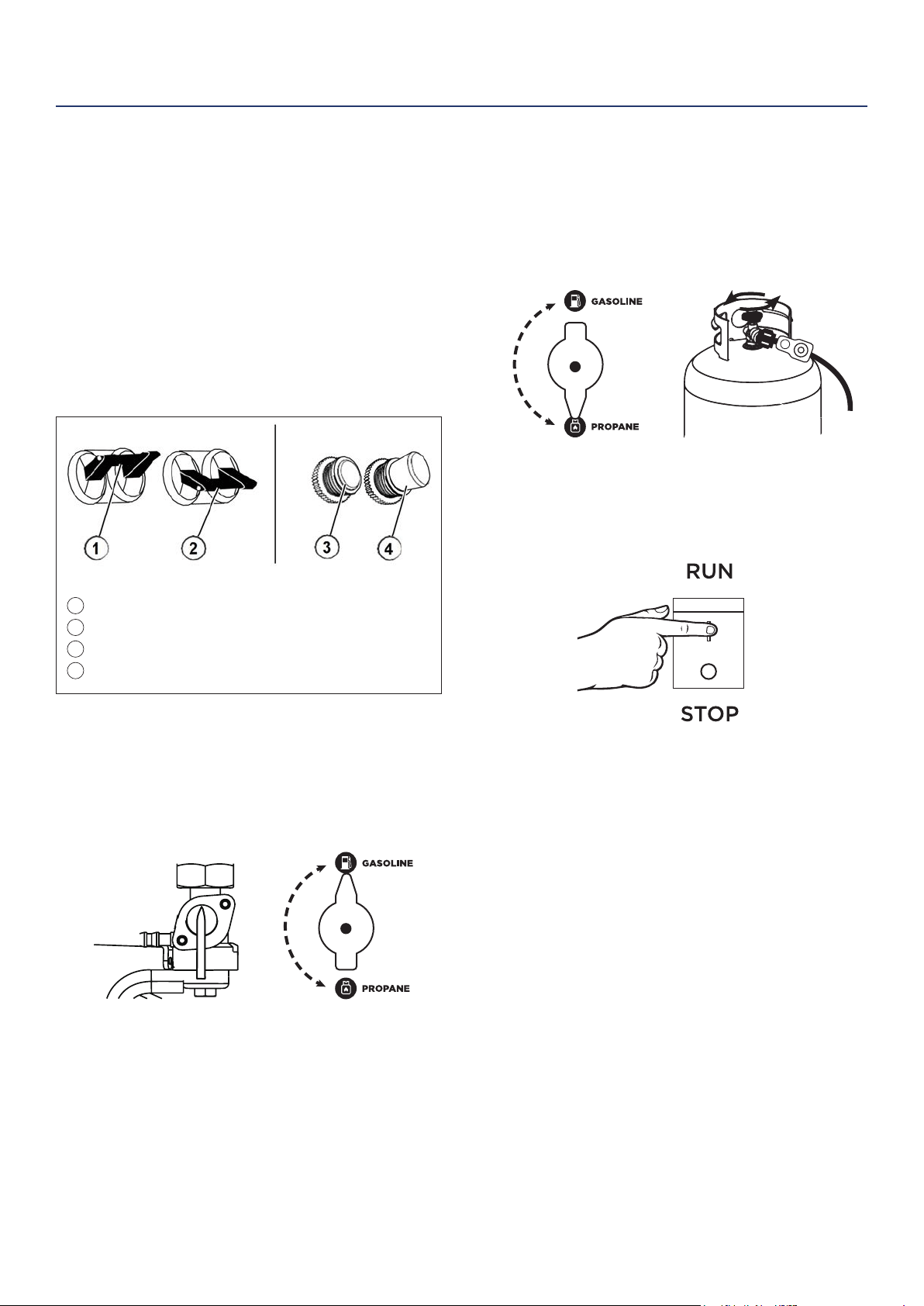
4. Select fuel source for start up:
FOR GASOLINE:
a. Move the fuel shut o valve to the ON position
(see Figure 9).
b. Turn fuel selector knob to GASOLINE (see
Figure 9).
Figure 9 - Fuel Shut O - ON
Fuel Selector - GASOLINE
FOR LPG/PROPANE:
a. Make sure the LPG hose is safely secured from
the generator to the tank (see Connecting the
LPG Tank on page 19).
b. Turn the fuel selector knob to PROPANE (see
Figure 10).
c. Fully open the valve on the propane tank.
5. Switch the engine switch to RUN (see Figure 11).
6. Choose starting method:
a. Recoil Start: Move the choke to the right then
rmly grasp and pull the recoil handle slowly
until you feel increased resistance. At this point,
apply a rapid pull while pulling up and slightly
away from the generator.
b. Remote Start: Click START on the wireless key
FOB provided.
c. Push Button Start: Push and hold the engine
start push button for 1 second and release.
• The engine will automatically set the choke and begin the
start sequence.
• If the engine has started successfully the light indicator
on the engine start button will turn green.
• If the engine fails to start, the generator controls will
attempt to start the engine two more times for a total of
three attempts.
• If the third attempt fails, the light on the engine start
button will turn red.
• If the engine has failed to start after three attempts the
engine start button can be pushed again to begin the
automatic start sequence.
• The red engine stop button can be pushed at any time
during the automatic start sequence to abort the engine
start attempt.
OPERATION
Figure 8 - Breakers
Figure 10 - Fuel Selector - PROPANE
Propane Tank Valve - OPEN
Figure 11 - Engine Switch - RUN
1
2
3
4
ON
OFF
22 | Westinghouse Portable Power
STOPPING THE GENERATOR
Normal Operation
During normal operation, use the following steps to
stop your generator:
1. Remove any connected loads from the control
panel receptacles.
2. Allow the generator to run at “no load” to reduce
and stabilize engine and alternator temperatures.
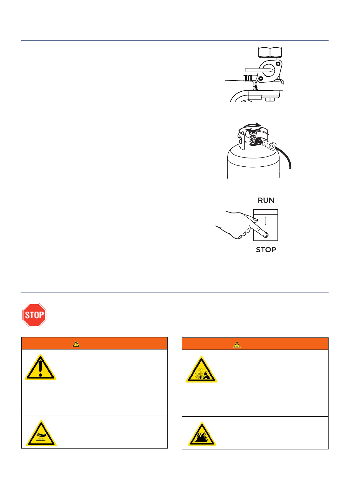
3. If you are operating on gas move the fuel shut o
valve to OFF (see Figure 14). If you are operating on
propane shut o the tank valve (see Figure 15). Wait
for engine to shut o due to lack of fuel.
4. To stop generator remotely simply push the STOP
button on the wireless control. The generator will
run for an additional 15 seconds as it goes through
a cool down cycle before shutting o.
5. Position the engine control switch to STOP (see
Figure 16).
During an Emergency
If there is an emergency and the generator must be
stopped quickly, position the engine control switch to
the STOP position immediately.
WARNING
Internal pressure can build in the
engine crankcase while the engine
is running. Removing the oil ll plug/
dipstick while the engine is hot can
cause extremely hot oil to spray out
of the crankcase and can severely
burn skin. Allow engine oil to cool for
several minutes before removing the
oil ll plug/dipstick.
Always perform maintenance in a well-
ventilated area. Gasoline fuel and fuel
vapors are extremely ammable and
can ignite under certain conditions.
WARNING
Avoid accidentally starting the
generator during maintenance by
removing the spark plug boot from
the spark plug. For electric start
generators, also disconnect the
battery cables from the battery
(disconnect the black negative (-)
cable rst) and place the cables away
from the battery posts to avoid arcing.
Allow hot components to cool to
the touch prior to performing any
maintenance procedure.
OPERATION
MAINTENANCE
Figure 16 - Engine Switch - STOP
Figure 14 - Fuel Shut O - OFF
Figure 15 - Propane Tank Valve - CLOSED
BEFORE PERFORMING MAINTENANCE ON THE GENERATOR, REVIEW THE
SAFETY SECTION STARTING ON PAGE 5, AS WELL AS THE FOLLOWING
SAFETY MESSAGES.
ON
OFF
Westinghouse Portable Power | 23
MAINTENANCE SCHEDULE
WARNING
Failure to perform periodic
maintenance or not following
maintenance procedures can cause
the generator to malfunction and
could result in death or serious injury.
NOTICE
Periodic maintenance intervals vary depending
on generator operating conditions. Operating the
generator under severe conditions, such as sustained
high-load, high-temperature, or unusually wet or
dusty environments, will require more frequent
periodic maintenance. The intervals listed in the
maintenance schedule should be treated only as a
general guideline.
MAINTENANCE
TABLE 1: MAINTENANCE SCHEDULE - OWNER PERFORMED
Maintenance Item
Before Every
Use
After First 20
Hours or First
Month of Use
After 50 Hours
of Use or Every
6 Months
After 100 Hour
of Use or Every
6 Months
After 300 Hours
of Use or Every
Year
Engine Oil
Check Level Change Change - -
Cooling Features
Check/Clean - - - -
Air Filter
Check - Clean* - Replace
Spark Plug
- - - Check/Clean Replace
Spark Arrestor
- - - Check/Clean -
*Service more frequently if operating in dry and dusty conditions
TABLE 2: MAINTENANCE SCHEDULE - AUTHORIZED WESTINGHOUSE
SERVICE DEALER PERFORMED
Maintenance Item
Before Every
Use
After First 20
Hours or First
Month of Use
After 50 Hours
of Use or Every
6 Months
After 100 Hour
of Use or Every
6 Months
After 300 Hours
of Use or Every
Year
Valve Clearance
- - - - Check/Adjust
Fuel Filter
- - - Check/Clean -
Idle Speed
- - - - Check/Adjust
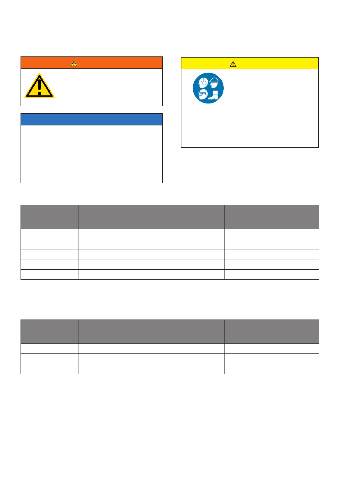
CAUTION
Avoid skin contact with engine
oil or gasoline. Prolonged
skin contact with engine oil
or gasoline can be harmful.
Frequent and prolonged
contact with engine oil may
cause skin cancer. Take
protective measures and
wear protective clothing and
equipment. Wash all exposed
skin with soap and water.
Following the maintenance schedule is important
to keep the generator in good operating condition.
The following is a summary of maintenance items by
periodic maintenance intervals.
24 | Westinghouse Portable Power
ENGINE OIL MAINTENANCE
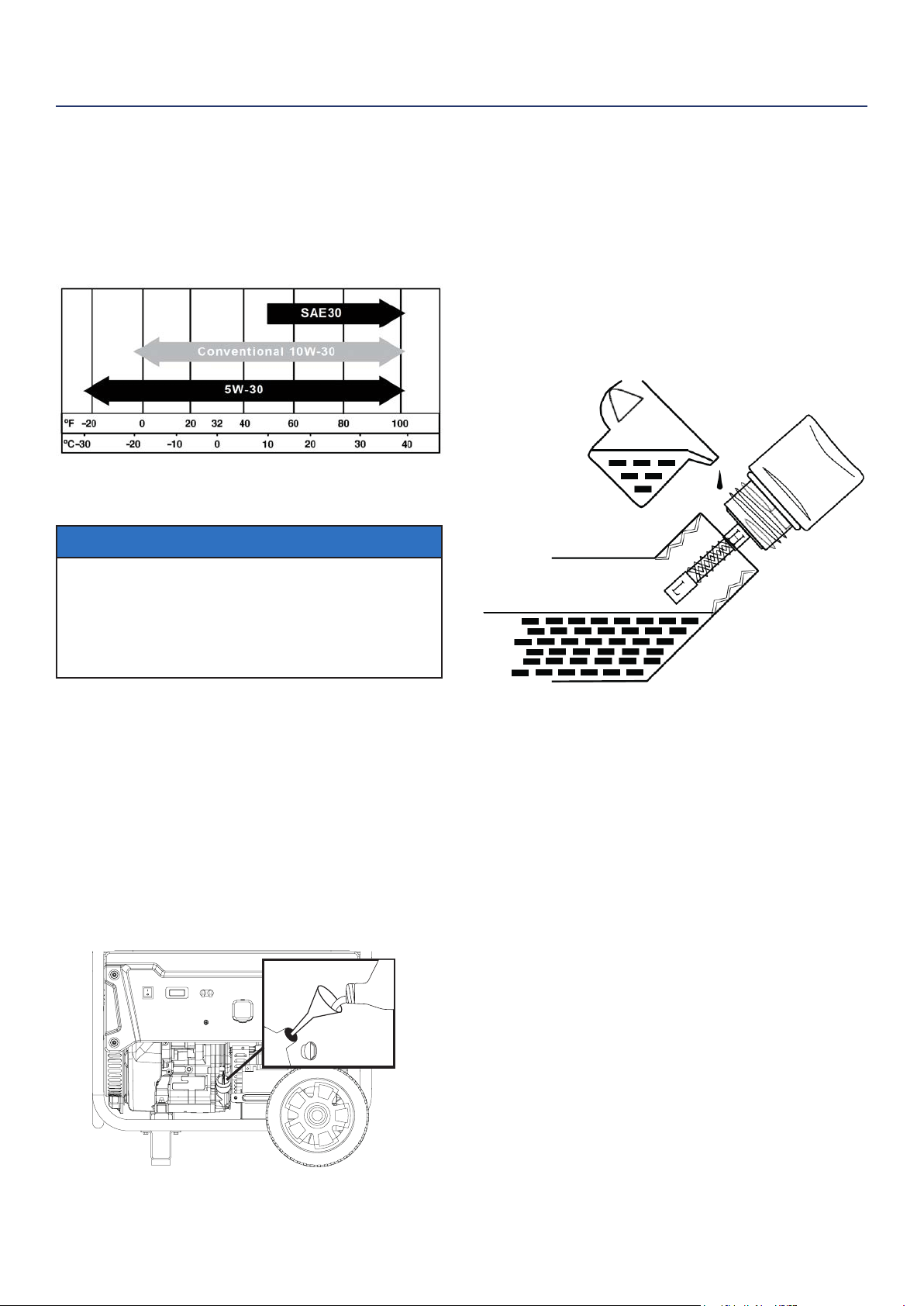
Engine Oil Specication
1. Only use the engine oil specied in Figure 17.
2. Only use 4-stroke/cycle engine oil. NEVER USE
2-STROKE/CYCLE OIL. Synthetic oil is an
acceptable substitute for conventional oil.
Figure 17 - Recommended Oil
CHECKING ENGINE OIL
NOTICE
Always maintain proper engine oil level. Failure to
maintain proper engine oil level could result in severe
damage to the engine and/or shorten the life of the
engine. Always use the specied engine oil. Failure
to use the specied engine oil can cause accelerated
wear and/or shorten the life of the engine.
Engine oil level should be checked before every use.
1. Always operate or maintain the generator
on a at surface.
2. Stop engine if running.
3. Let engine sit and cool for several minutes (allow
crankcase pressure to equalize).
4. With a damp rag, clean around the
oil ll plug/dipstick.
5. Remove oil ll plug/dipstick (see Figure 18 below).
Figure 18 - Oil Fill Plug/Dipstick
6. Check oil level: When checking the engine oil,
remove the oil ll plug/dipstick and wipe it clean.
Thread the oil ll plug/dipstick all the way back in
and then remove and check the oil level on the oil
ll plug/dipstick.
• Acceptable Oil Level – Oil is visible on the
crosshatches between the H and L lines on the oil
ll plug/dipstick (see Figure 19).
• Low Oil – Oil is below the L line on the oil ll
plug/ dipstick.
Figure 19 - Checking Oil Level
ADDING ENGINE OIL
1. Always operate or maintain the generator
on a at surface.
2. Stop engine if running.
3. Let engine sit and cool for several minutes (allow
crankcase pressure to equalize).
4. Thoroughly clean around the oil ll plug/dipstick.
5. Remove oil ll plug/dipstick and wipe clean.
6. Select the proper engine oil as specied
in Figure 17.
7. Using the supplied funnel and tube, slowly add
engine oil to the engine. Stop frequently to check
the level to avoid overlling.
8. Continue to add oil until the oil is at the correct
level. See Figure 19.
MAINTENANCE
Westinghouse Portable Power | 25
AIR FILTER MAINTENANCE
WARNING
Never use gasoline or other ammable
solvents to clean the air lter. Use only
household detergent soap to clean the
air lter.
Cleaning the Air Filter
The air lter must be cleaned after every 50 hours of
use or 3 months (frequency should be increased if
generator is operated in a dusty environment).
1. Turn o the generator and let it cool for several
minutes if running.
2. Move the generator to a at, level surface.
3. Unclip the clips on the top and bottom of the air
lter cover (Figure 21).
4. Remove the black coarse air lters.
5. Wash the foam air lter elements by submerging
the elements in a solution of household detergent
soap and warm water. Slowly squeeze the foam to
thoroughly clean.
NOTICE
NEVER twist or tear the foam air lter element
during cleaning or drying. Only apply slow but rm
squeezing action.
6. Rinse in clean water by submerging the air lter
elements in fresh water and applying a slow
squeezing action
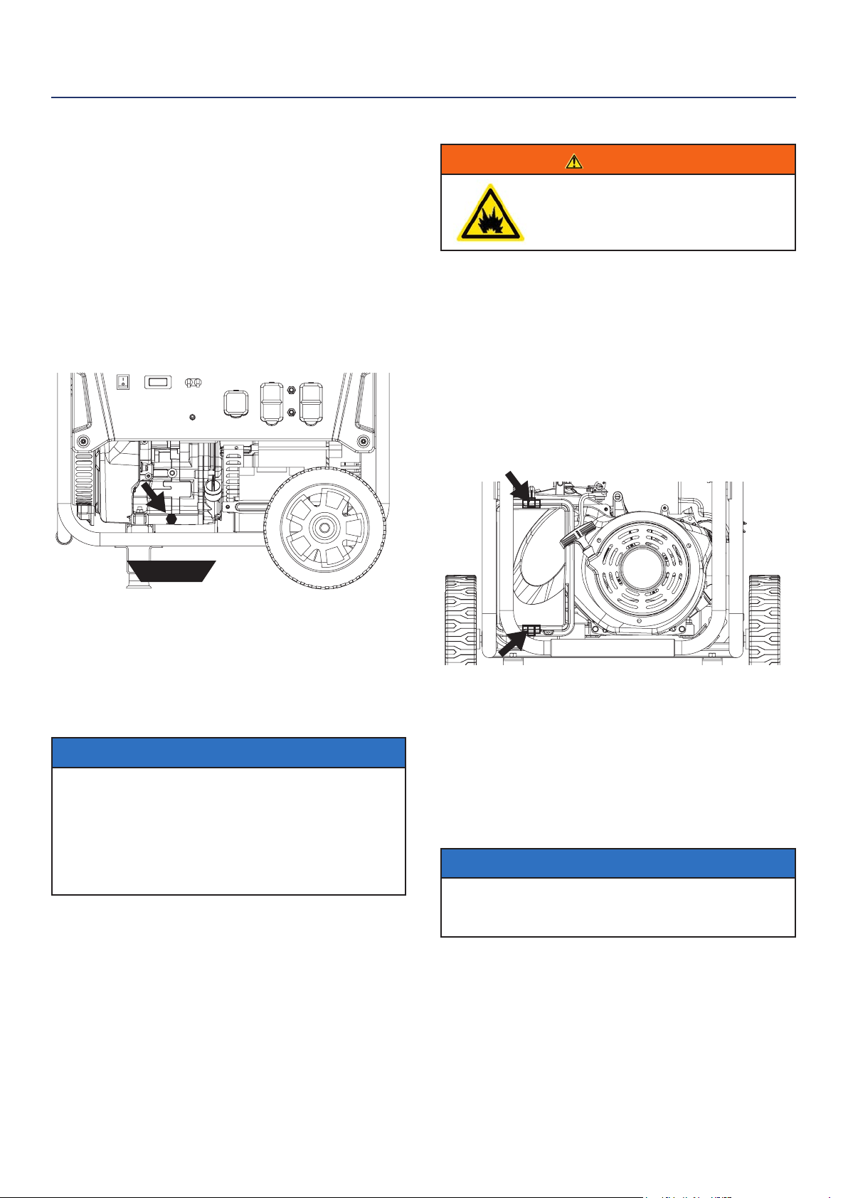
CHANGING ENGINE OIL
1. Stop the engine.
2. Let engine sit and cool for several minutes (allow
crankcase pressure to equalize).
3. Place oil pan (or suitable container) under the oil
drain plug (see Figure 20).
4. With a damp rag, thoroughly clean around the oil
drain plug.
5. Remove the oil drain plug (see Figure 20). Once
removed, place the oil drain plug on a clean
surface.
Figure 20 - Oil Drain Plug
6. Allow oil to completely drain.
7. Replace oil drain plug.
8. Fill crankcase with oil following the steps outlined in
Adding Engine Oil on page 24.
NOTICE
Never dispose of used engine oil by dumping the
oil into a sewer, on the ground, or into ground
water or waterways. Always be environmentally
responsible. Follow the guidelines of the EPA or
other governmental agencies for proper disposal
of hazardous materials. Consult local authorities or
reclamation facility.
MAINTENANCE
Figure 21 - Clips on air lter
oil pan
26 | Westinghouse Portable Power
Cleaning the Air Filter - Continued from Page 25
NOTICE
Never dispose of soap cleaning solution used to
clean the air lter by dumping the solution into
a sewer, on the ground, or into ground water or
waterways. Always be environmentally responsible.
Follow the guidelines of the EPA or other
governmental agencies for proper disposal of
hazardous materials. Consult local authorities or
reclamation facility.
7. Dispose of used soap cleaning solution properly.
8. Dry the air lter elements by again applying a slow
rm squeezing action.
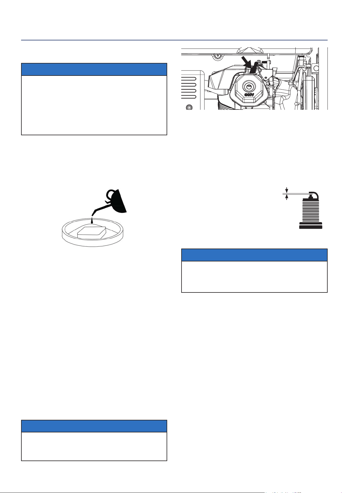
9. Once the air lters are dry, coat the air lters with
clean engine oil (see Figure 22 below).
Figure 22
10. Squeeze the lters to remove any excess oil.
11. Install the lters back into the unit. If there are two
lters make sure the gray (ne) air lter goes in
rst followed by the black (coarse) air lter on the
outside.
12. Install the air lter cover and secure the air lter
assembly.
SPARK PLUG MAINTENANCE
The spark plug must be checked and cleaned after
every 100 hours of use or 6 months and must be
replaced after 300 hours of use or every year.
1. Stop the generator and let it cool for several
minutes if running.
2. Move the generator to a at, level surface.
3. Remove the spark plug boot by rmly pulling the
plastic spark plug boot handle directly away from
the engine (see Figure 23).
NOTICE
Never apply any side load or move the spark plug laterally
when removing the spark plug. Applying a side load or
moving the spark plug laterally may crack and damage the
spark plug boot.
Figure 23 - Remove Spark Plug Boot
4. Clean area around the spark plug.
5. Using the 13/16” spark plug socket wrench
provided, remove the spark plug from the cylinder
head.
6. Place a clean rag over the opening created by the
removal of the spark plug to make sure no dirt can
get into the combustion chamber.
Inspect the spark plug for:
• Cracked or chipped insulator
• Excessive wear
• Spark plug gap (the acceptable
limit of 0.027–0.032 in.
[0.70 – 0.80 mm]) (see Figure 24).
NOTICE
Use only recommended spark plugs when servicing.
The manufacturer is not responsible for engine
damage when using spark plugs not recommended
by the manufacturer.
7. Install the spark plug by carefully following the
steps outlined below:
a. Carefully insert the spark plug back into the
cylinder head. Hand-thread the spark plug until
it bottoms out.
b. Using the 13/16” spark plug socket wrench
provided, turn the spark plug to ensure it is fully
seated.
c. Replace the spark plug boot, making sure the
boot fully engages the spark plug’s tip.
Recommended Spark Plug Replacement:
AC Delco: 4EXLS
Autolite: 52
Champion: N9YC
Bosch: W7DC
Torch: F7TC
MAINTENANCE
SPARK PLUG GAP
Figure 24
Westinghouse Portable Power | 27
8. Recheck the valve lash after tightening the jam nut.
9. Perform this procedure for both the intake and
exhaust valves.
10. Install the rocker arm cover, gasket and spark plug.
BATTERY SERVICE
To ensure the battery remains charged, the generator
should be started every 2 to 3 months and run for a
minimum of 15 minutes or the charger (included) should
be plugged into the generator and the generator should
be charged overnight. Make sure the engine control
switch is in the “RUN” position when charging. Plug the
cord from the charger into the charging port on the gen-
erator. Plug the charger into a 110/120-volt AC outlet.
CLEANING THE GENERATOR
It is important to inspect and clean the generator before
every use.
Clean All Engine Air Inlet and Outlet Ports – Make
sure all engine air inlet and outlet ports are clean of any
dirt and debris to ensure the engine does not run hot.
Clean All Engine Cooling Fins – Use a damp rag and
a brush to loosen and remove all dirt on or around the
engine’s cooling ns.
Clean All Alternator Cooling Air Inlets and Exhaust
Ports – Make sure the cooling air inlets and exhaust
ports of the alternator are free of any debris and ob-
structions. Use a vacuum cleaner to remove dirt and
debris stuck in the cooling air inlets and exhaust ports.
General Cleaning of the Generator – Use a damp rag
to clean all remaining surfaces.
STORING GENERATOR
WARNING
Never store a generator with fuel in the tank
indoors or in a poorly ventilated area where the
fumes can come in contact with an ignition source
such as a: 1) pilot light of a stove, water heater,
clothes dryer or any other gas appliance; or 2)
spark from an electric appliance.
NOTICE
Gasoline stored for as little as 60 days can go bad, causing gum,
varnish and corrosive buildup in fuel lines, fuel passages and the
engine. This corrosive buildup restricts the ow of fuel, preventing
an engine from starting after a prolonged storage period.
Proper care should be taken to prepare the generator for
any storage.
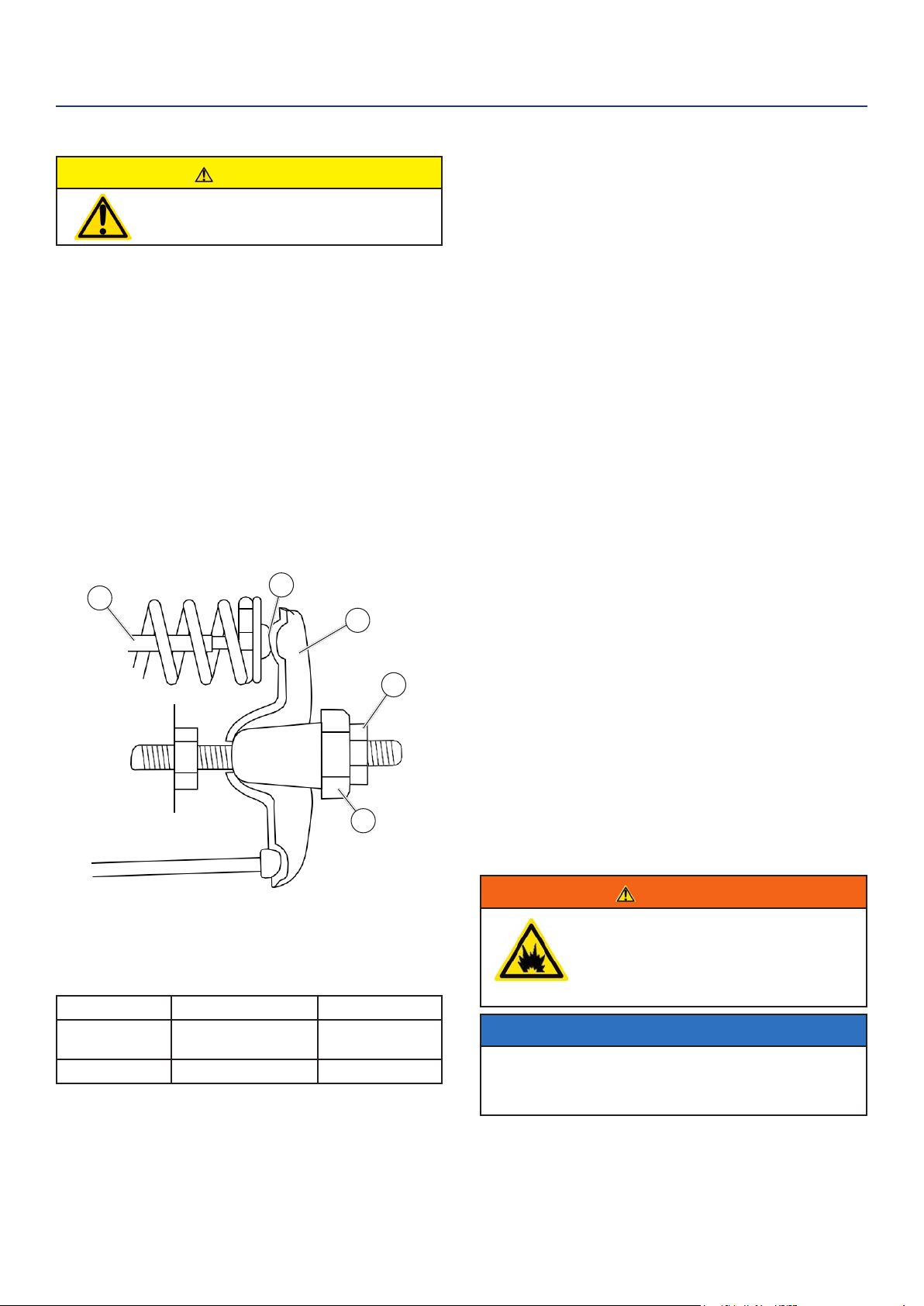
CHECKING AND ADJUSTING VALVE LASH
CAUTION
Checking and adjusting valve lash
must be done when the engine is cold.
1. Remove the rocker arm cover and carefully remove
the gasket. If the gasket is torn or damaged, it must
be replaced.
2. Remove the spark plug so the engine can be
rotated more easily.
3. Rotate the engine to top dead center (TDC) of the
compression stroke. Looking through the spark
plug hole, the piston should be at the top.
4. Both the rocker arms should be loose at TDC on
the compression stroke. If they are not, rotate the
engine 360°.
5. Insert a feeler gauge between the rocker arm and
the push rod and check for clearance (see Figure
25). See Table 2 for valve lash specications
Figure 25
(1) Push Rod, (2) Feeler Gauge Area
(3) Rocker Arm, (4) Jam Nut, (5) Adjusting Nut
(Table 2) Standard Valve Lash
Intake Valve Exhaust Valve
Valve Lash
0.0035 ± 0.0043 in
(0.09 ± 0.11 mm)
0.0043 ± 0.0051 in
(0.11 ± 0.13 mm)
Bolt Torque
8-12N.m 8-12N.m
6. If an adjustment is required, hold the adjusting nut
and loosen the jam nut.
7. Turn the adjusting nut to obtain the correct valve
lash. When the valve lash is correct, hold the ad-
justing nut and tighten the jam nut to 106 in-lb (12
N•m).
MAINTENANCE
1
2
3
4
5
28 | Westinghouse Portable Power
Storing Generator - Continued from page 27
1. Make sure the Engine Switch is switched to STOP
so the generator does not draw power from battery.
2. Clean the generator as outlined in Cleaning the
Generator.
3. Drain all gasoline from the fuel tank as best as
possible.
4. With the fuel shut o valve open, start the engine
and allow the generator to run until all the remaining
gasoline in the fuel lines and carburetor is consumed
and the engine shuts o. If you used propane the
last time you ran the generator: start the unit up
with propane then shut o the propane tank valve
allowing the engine to use up all the remanding
propane in the carburetor before it shuts o.
5. Close the fuel shut o valve.
6. Change the oil (see Changing Engine Oil on page
25).
7. Remove the spark plug (see Spark Plug Maintenance
on page 26) and place about 1 tablespoon of oil in
the spark plug opening. While placing a clean rag
over the spark plug opening, slowly pull there coil
handle to allow the engine to turn over several times.
This will distribute the oil and protect the cylinder
wall from corroding during storage.
8. Replace the spark plug (see Spark Plug Maintenance
on page 26).
9. Move the generator to a clean, dry place for storage.
MAINTENANCE
WARNING
Before attempting to service or troubleshoot the generator, the owner or service technician must rst read the owner’s
manual and understand and follow all safety instructions. Failure to follow all instructions may result in conditions that
can lead to voiding of the EPA certication or product warranty, serious personal injury, property damage or even death.
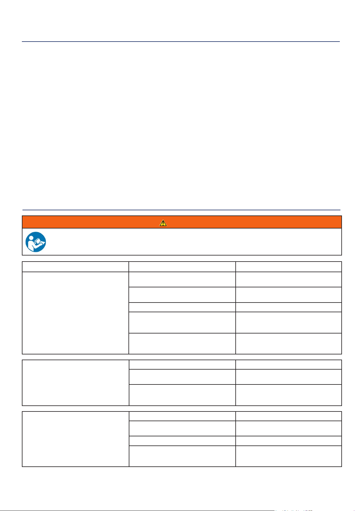
TROUBLESHOOTING
PROBLEM POTENTIAL CAUSE SOLUTION
Engine is running, but no
electrical output
1. Circuit breakers are tripped. 1. Reset the circuit breakers and check for
overload condition.
2. The power cord’s plug connector is not fully
engaged in the generator’s outlet.
2. Verify plug connector is rmly engaged in
the generator’s outlet.
3. Faulty or defective power cord 3. Replace power cord.
4. Faulty or defective electrical appliance 4. Try connecting a known good appliance
to verify the generator is producing electrical
power.
5. If trying 1-4 above does not solve the
problem, the cause might be the generator has
a fault.
6. Take the generator to your nearest
authorized service dealer.
Engine runs
erratic; does not hold a
steady RPM.
1. Dirty air lter 1. Clean the air lter (see pages 25-26).
2. Applied loads maybe cycling on and o 2. As applied loads cycle, changes in engine
speed may occur; this is a normal condition.
3. If trying 1-2 above does not solve
the problem, the cause might be a
fault in the generator
3. Take the generator to your nearest
authorized service dealer.
Generator suddenly
stops running.
1. Generator is out of fuel. 1. Check fuel level. Add fuel if necessary.
2. The low oil shut down switch has stopped
the engine.
2. Check oil level and add oil if necessary (see
page 24).
3. Too much load 3. Restart the generator and reduce the load.
4. If trying 1-3 above does not solve the
problem,the cause might be a fault in the
generator.
4. Take the generator to your nearest
authorized service dealer.

Westinghouse Portable Power | 29
TROUBLESHOOTING
Frost on the propane tank or
regulator
1. This can be a normal occurrence caused
when liquid propane changes phase to a
gas. As this process occurs the fuel tank
or regulator will cool and allow humid air
surrounding the propane tank or regulator to
condense into frost.
1. As this can be normal, providing all
the propane fuel handling equipment is
functioning normally, no remedy is needed.
2. The propane tank is not equipped with a
OPD (rollover protection device) and has been
stored in a horizontal position allowing liquid
propane to enter the downstream fuel handling
equipment.
2. If you suspect your propane fuel tank is
not equipped with a OPD device, discontinue
operation immediately and replace the
propane fuel tank with a propane tank
equipped with a roll over protection device.
3. Propane fuel tank over lled. 3. If you suspect your propane fuel tank
has been overlled, discontinue operation
immediately and return the propane fuel tank
to the place of purchase or relling.
Propane fuel smell
1. Fuel regulator or fuel hose and ttings not
securely sealed.
1. Using a soap solution check each
connection and tighten as needed.
2. Propane fuel regulator vent active. 2. The propane fuel regulator is equipped with
a small vent that will allow a small amount
of propane fuel vapor to escape from the
regulator when the propane tank valve is
opened. This can be normal providing the
venting of the propane is brief. If you suspect
that this is abnormal, immediately discontinue
use and have the propane regulator inspected
by a qualied technician.
3. Residual fuel from the carburetor dispersing
after operation.
3. Normal, no remedy is needed.
Poor performance or engine
stalling on propane
1. Propane fuel line kinked or crushed. 1. Inspect propane fuel line and remove kinks
or other obstructions.
2. Fuel selector valve not properly positioned. 2. Rotate the fuel valve fully until the pointer is
directly in line with the desired fuel.
3. Gasoline not purged from the carburetor
before switching to propane.
3. Turn the propane fuel tank valve to closed.
Move the fuel selector valve to propane. Turn
the gasoline fuel valve to o. Start the engine
and allow the engine to run until the fuel has
been consumed in the carburetor. Begin
propane start up procedure.
Engine will not start or
remain running while
trying to start.
1. Fuel shuto valve is in the OFF position. 1. Move the fuel shut o valve to the ON
position (see Figure 9 page 21).
2. Generator is out of gasoline. 2. Add gasoline to the generator (see page
19).
3. Fuel ow is obstructed. 3. Inspect and clean fuel delivery passages.
4. Starting battery may have insucient charge 4. On electric start models only. Check battery
output and charge battery as necessary.
5. Dirty air lter 5. Check and clean the air lter (see page 25).
6. Low oil level shut down switch is preventing
the unit from starting.
6. Check oil level and add oil if necessary (see
page 24).
7. Spark plug boot is not fully engaged with
the spark plug tip.
7. Firmly push down on the spark plug boot to
ensure the boot is fully engaged
8. Spark plug is faulty. 8. Remove and check the spark plug. Replace
if faulty (see page 26).
9. Dirty/plugged spark arrestor 9. Check and clean the spark arrestor.
10. Stale fuel 10. Drain fuel and replace with fresh fuel.
11. If trying 1-10 above does not solve the
problem, the cause might be the generator has
a fault.
11. Take the generator to your nearest
authorized service dealer.
30 | Westinghouse Portable Power
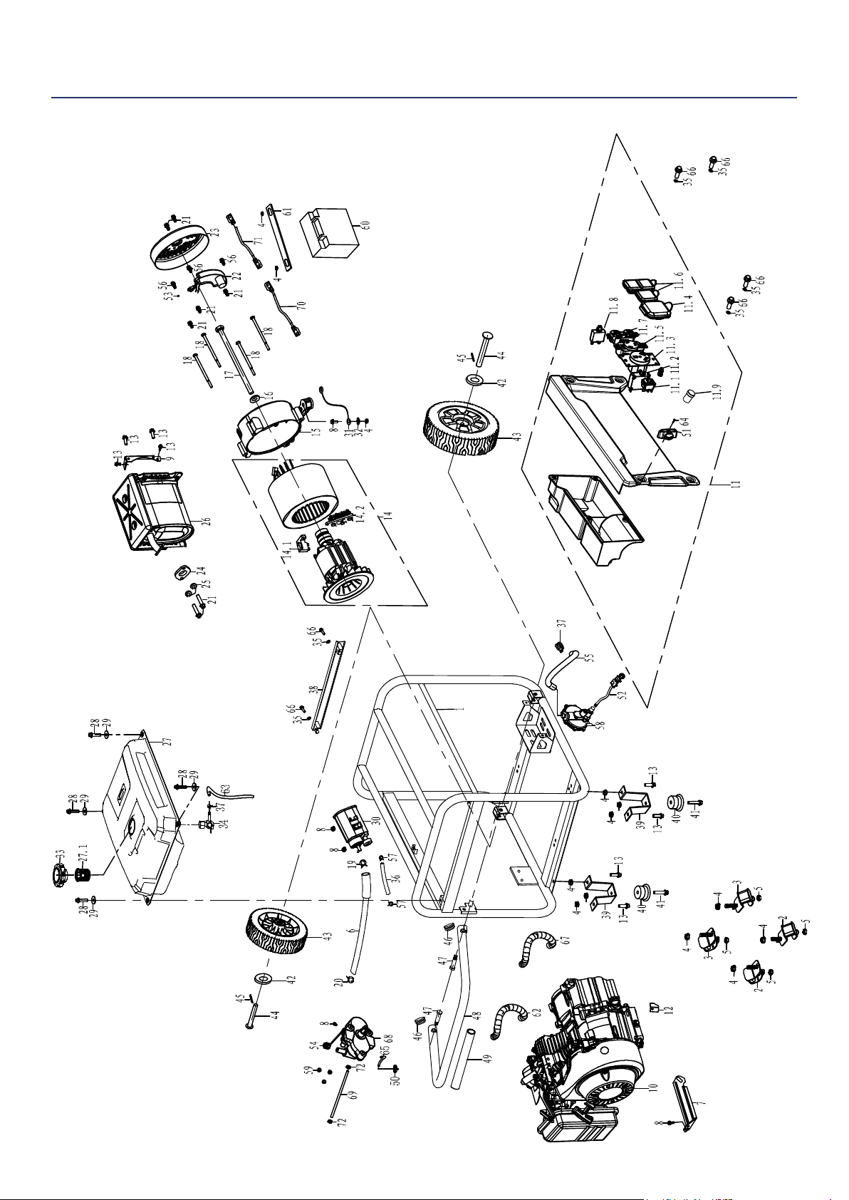
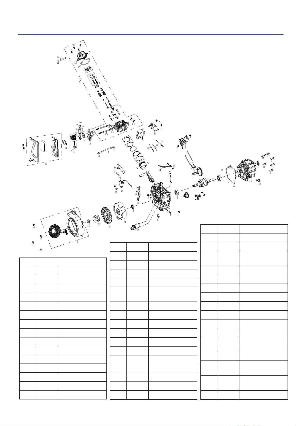
WGen3600DF EXPLODED VIEW

Westinghouse Portable Power | 31
WGen3600DF EXPLODED PART NO.
No. Part. Description
1 100608 Frame
2 105560 Damper
3 100559 Damper
4 100520 M8 Nut
5 180524 M8 Nut
6 150519 Hose
7 180569 Bracket
8 120539 M6X12
9 110520 Bracket
10 180595 Engine Assy
11 130554 Panel Complete
11.1 130534 Stop Switch
11.2 130547 GFCI Breaker
1P30A
11.3 130511 TT-30 Receptacle
11.4 130555 TT-30R Dust
Cover
11.5 130550 L5-30 Receptacle
11.6 130512 R5-20 Receptacle
11.7 130549 Dust Cover TT-
30R
11.8 130533 Circuit Breaker
1P20A
11.9 130528 Start Switch
12 180568 Dust Plate
13 100516 M8X16
14 120546 Alternator Assy
14.1 120525 Brush Assy
14.2 120526 Terminal Block
15 120527 Rear Bearing
Carrier
16 120532 Washer
17 120531 M8X220
18 120521 M6X165
19 150545 Hose Clamp
20 150550 Hose Clamp
21 120537 M5X12
22 120529 AVR
23 120545 Alternator Cover
24 110519 Gasket
25 110502 Spring Washer
26 110518 Muer Assy
27 150551 Fuel Tank
27.1 150506 Fuel Strainer
28 120541 M5X25
29 150547 M6 Washer
30 150520 Carbon Canister
31 120528 Ground Strap
32 120533 M6 Washer
33 150505 Fuel Tank Cap
34 150552 Fuel Valve
35 100547 Washer
36 150522 Hose
37 150553 Hose Clamp
38 100530 Bracket
39 100541 Foot Bracket
40 100515 Rubber Pad
41 100582 M6X28
42 100510 Washer
43 100538 Wheel
44 100537 Axle Pin
45 100508 Cotter Pin
46 100546 Plug
47 100545 Handle Fastener
48 100543 Handle
49 100544 Handle Cover
50 100593 Fuel Filter
51 130539 Fuel Selector
Knob
52 100594 High Pressure
Regulator
53 120512 M5 Lock Washer
54 100595 Regulator Cap
55 100610 Fuel Hose
56 120518 M5X16
57 150549 Hose Clamp
58 100603 Fuel Regulator
59 100583 M5 Nut
60 100579 Battery
61 110524 Battery Hold
Down
62 100607 Conduit
63 100611 Fuel Hose
64 130535 Allen Head Bolt
65 150554 Fuel Hose
66 130536 M6X16
67 100612 Conduit
68 130538 Fuel Selector
Valve
69 100610 Fuel Hose
70 100584 Positive Lead
71 100613 Negative Lead
72 100588 Hose Clamp
32 | Westinghouse Portable Power
WGen3600DF ENGINE VIEW
No. Part. Description
1 180556 Ball Bearing
2 180541 Oil Seal
3 180543 Drain Plug
4 180544 Drain Plug Seal
5 180546 Crankcase Cover
6 170518 Harness Clamp
7 180596 Cylider Head Assy
7.1 180526 Spark Plug
7.2 180555 Valve Cover Gasket
7.3 180554 Valve Cover
7.4 140515 M6 Stud
7.5 140516 Gasket
7.6 180571 M10X80 Stud
8 140552 Carburetor Assy
9 140553 Fuel Hose
10 140508 Hose Clamp
11 180549 Govenor Arm
12 100548 M6 Nut
13 180545 Gasket
14 110503 M8X30
15 180547 Cylinder Head
Gasket
16 180553 Heat Shield
17 120505 M6X12
18 180597 Dust Plate
19 180567 M6X20
20 180598 Flywheel Assy
21 180539 Engine Cooling Fan
22 180538 Starter Cup
23 180537 Crankshaft Nut
24 180599 Ignition Coil Assy
25 100518 M6X25
26 140514 Spacer
27 140513 Gasket
28 140554 Gasket
29 180570 Govenor Linkage
30 180551 Throttle Return
Spring
31 170519 Recoil Assy
32 180552 Govenor Bracket
33 160501 Air Cleaner Assy
34 180559 Vent
35 140506 Fitting
36 180550 Govenor Spring
37 180600 Dip Stick
38 170520 Engine Starter
39 140555 Stepper Motor
Bracket
40 140556 Spring
41 140557 Stepper Motor
Coupling Shaft
42 140558 Stepper Motor
Fastener
43 140559 Stepper Motor
Westinghouse Portable Power | 33
27 140513 Gasket
28 140554 Gasket
29 180570 Govenor Linkage
30 180551 Throttle Return
Spring
31 170519 Recoil Assy
32 180552 Govenor Bracket
33 160501 Air Cleaner Assy
34 180559 Vent
35 140506 Fitting
36 180550 Govenor Spring
37 180600 Dip Stick
38 170520 Engine Starter
39 140555 Stepper Motor
Bracket
40 140556 Spring
41 140557 Stepper Motor
Coupling Shaft
42 140558 Stepper Motor
Fastener
43 140559 Stepper Motor
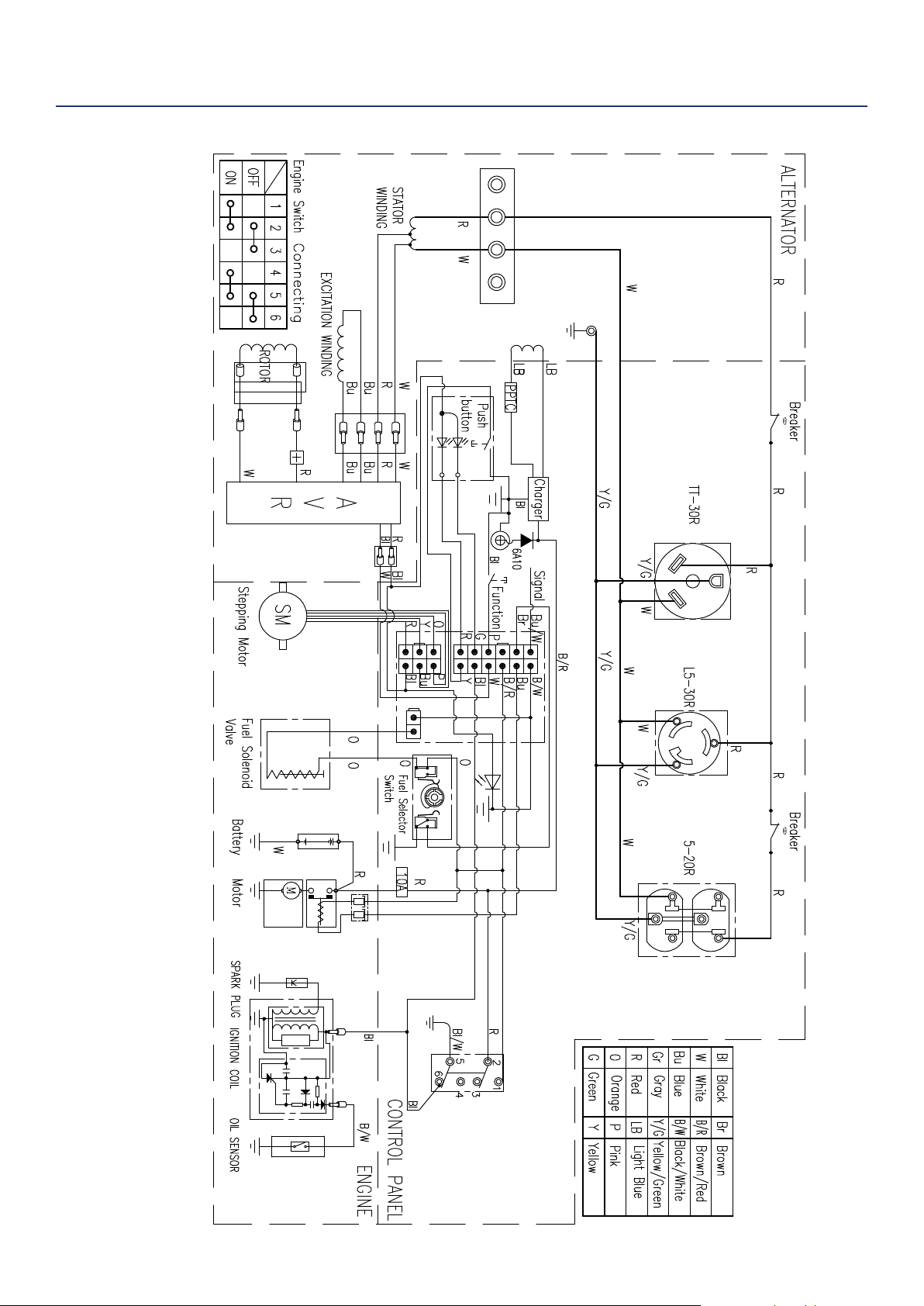
WGen3600DF SCHEMATIC
WGen3600DF

34 | Westinghouse Portable Power
MAINTENANCE NOTES

Westinghouse Portable Power | 35
MAINTENANCE NOTES

36 | Westinghouse Portable Power
Version 9.25.17KD
