USER MANUAL
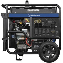
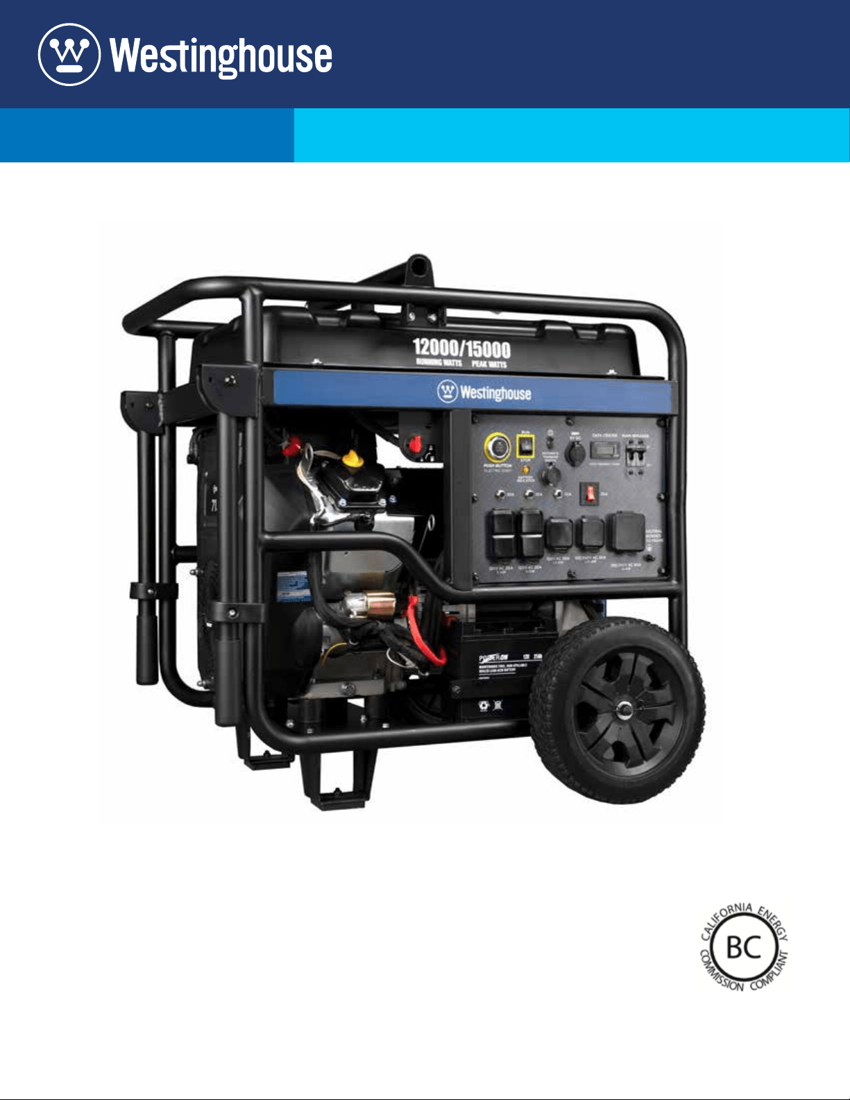
WGen12000
Portable Generator
12,000 Running Watts | 15,000 Peak Watts

2 | Westinghouse Outdoor Power Equipment
DISCLAIMERS:
All information, illustrations and specications in this manual are based on the latest information available at the time of
publishing. The illustrations used in this manual are intended as representative reference views only. Moreover, because
of our continuous product improvement policy, we may modify information, illustrations and/or specications to explain
and/or exemplify a product, service or maintenance improvement. We reserve the right to make any change at any time
without notice. Some images may vary depending upon which model is shown.
ALL RIGHTS RESERVED:
No part of this publication may be reproduced or used in any form by any means – graphic, electronic or
mechanical, including photocopying, recording, taping or information storage and retrieval systems – without the
written permission of MWE Investments LLC.
DANGER
This manual contains important instructions for operating this generator. For your safety
and the safety of others, be sure to read this manual thoroughly before operating the
generator. Failure to properly follow all instructions and precautions can cause you and
others to be seriously hurt or killed.
Model
Number
Running
Watts
Peak
Watts
Fuel Tank Size
(L/G)
Rated
Speed
(RPM)
Ignition
Type
Spark
plug
Engine
Disp (cc)
Stroke X
Bore
Oil
Capacity
(L) Oil Type THD
WGen12000 12000 15000 40 L
10.5 G
3600 TCI Bosch
F7TC
713cc 71X80 1.6 L 10W30 <5%
NOTICE
This generator is not equipped with altitude carburetor modication. Even with a carburetor modication, engine horsepower will decrease
about 3.5% for each 300 meter (1,000 foot) increase in altitude. The eect of altitude on horsepower will be greater if no carburetor
modication is made. A decrease in engine horsepower will decrease the power output of the generator. Contact our service team to order
altitude kits.
WGen TECHNICAL SPECIFICATIONS
HAVE QUESTIONS?
Email us at service@wpowereq.com
or call 1-855-944-3571
Operating, servicing and maintaining this equipment can expose you to chemicals including engine exhaust,
carbon monoxide, phthalates, and lead, which are known to the State of California to cause cancer and birth
defects or other reproductive harm. To minimize exposure, avoid breathing exhaust, do not idle the engine
except as necessary, service your equipment in a well-ventilated area and wear gloves or wash your hands
frequently when servicing your equipment. For more information go to www.P65Warnings.ca.gov.
WARNING

Westinghouse Outdoor Power Equipment | 3
FOR YOUR RECORDS:
Date of Purchase:
Generator Model Number:
Purchased from Store/Dealer:
Generator Serial Number:
IMPORTANT: KEEP YOUR PURCHASE RECEIPT TO ENSURE TROUBLE-FREE WARRANTY
COVERAGE.
PRODUCT REGISTRATION
To ensure trouble-free warranty coverage, it is important you register your Westinghouse generator.
You can register your generator by either:
1. Filling in the product registration form below and mailing to:
Product Registration
MWE Investments LLC
777 Manor Park Drive
Columbus, Ohio 43228
2. Registering your product Online at www.westinghouseportablepower.com/register
To register your generator you will need to locate the following information:
WESTINGHOUSE PRODUCT REGISTRATION FORM
PERSONAL INFORMATION GENERATOR INFORMATION
First Name: _______________________________________ Model Number: _____________________________________
Last Name: _______________________________________ Serial Number: ______________________________________
Street Address: ___________________________________ Date Purchased: ____________________________________
Street Address: ___________________________________ Purchased From: ____________________________________
City, State, ZIP: ____________________________________
Country: __________________________________________
Phone Number: ___________________________________
E-Mail: ___________________________________________
Model info decal located on back side
above muer
Serial Number which is located on
right side of model info decal
SERIAL NUMBER

4 | Westinghouse Outdoor Power Equipment
TABLE OF CONTENTS
WGEN TECHNICAL SPECIFICATIONS ............2
PRODUCT REGISTRATION .....................3
For Your Records: ..........................3
Product Registration .......................3
Product Registration Form ...................3
SAFETY .....................................5
Safety Denitions ..........................5
Safety Symbol Denitions ...................5
General Safety Rules ........................6
UNPACKING .................................7
What Comes in the Box ......................7
ASSEMBLY .................................8
Installing Wheels and Feet ....................8
Installing Lift Bracket ........................8
Installing the Battery ........................9
FEATURES .................................10
Generator Features .........................10
Control Panel Features .....................11
OPERATION .................................12
Before Starting the Generator .................12
High Altitude Operation ......................13
How to Ground Generator ....................13
Connecting the Generator to Building Electrical ...13
System
How to Float the Neutral .....................13
Power Cords .............................14
How to use Lifting Bracket ...................14
Engine Fluids and Fuel .......................15
Adding Gasoline to the Fuel Tank .............15
Power Output and Demand ...................16
Starting the Generator ......................18
Electric Start ..............................18
Remote Start ..............................18
Stopping the Generator ......................19
Normal Operation .........................19
During an Emergency ......................19
MAINTENANCE ..............................20
Maintenance Schedule ......................20
Engine Oil Maintenance .....................21
Engine Oil Specication .....................21
Checking Engine Oil . . . . . . . . . . . . . . . . . . . . . . . . 21
Adding Engine Oil .........................21
Changing Engine Oil .......................22
Air Filter Maintenance .......................22
Cleaning the Air Filter .......................22
Spark Plug Maintenance .....................23
VFT Maintenance Reminders ..................23
Checking and Adjusting Valve Lash ..............24
Battery Service. . . . . . . . . . . . . . . . . . . . . . . . . . . . . 24
Battery Replacement .......................24
Cleaning the Generator ......................25
Cleaning Spark Arrestor ......................25
Storage ..................................25
TROUBLE SHOOTING .........................26
EXPLODED AND ENGINE VIEWS ................28
WGen12000 Exploded View ..................28
WGen12000 Exploded View Part Numbers .......29
WGen12000 Engine View ....................30
WGen12000 Engine View Part Numbers .........31
WGen12000 Schematic ......................33

Westinghouse Outdoor Power Equipment | 5
SAFETY DEFINITIONS
The words DANGER, WARNING, CAUTION and
NOTICE are used throughout this manual to highlight
important information. Be certain that the meanings of
these alerts are known to all who work on or near the
equipment.
This safety alert symbol appears
with most safety statements. It
means attention, become alert, your
safety is involved! Please read and
abide by the message that follows
the safety alerts symbol.
DANGER
Indicates a hazardous situation which, if not
avoided, will result in death or serious injury.
WARNING
Indicates a hazardous situation which, if not
avoided, could result in death or serious injury.
CAUTION
Indicates a hazardous situation which, if not
avoided, could result in minor or moderate injury.
NOTICE
Indicates a situation which can cause damage
to the generator, personal property and/or the
environment, or cause the equipment to operate
improperly.
NOTE: Indicates a procedure, practice or condition
that should be followed in order for the
generator to function in the manner
intended.
SAFETY
SAFETY SYMBOL DEFINITIONS
Explosion Hazard
Fire Hazard
Electrical Shock Hazard
Lifting Hazard
Pinch-Point Hazard
Read Manufacturer’s Instructions
Read Safety Messages
Before Proceeding
Wear Personal Protective
Equipment (PPE)
Safety Alert Symbol
Asphyxiation Hazard
Burn Hazard
Burst/Pressure Hazard
Don’t leave tools in the area
Symbol Description

6 | Westinghouse Outdoor Power Equipment
DANGER
Never use the generator in a location that is wet or damp. Never expose the generator to rain, snow, water
spray or standing water while in use. Protect the generator from all hazardous weather conditions. Moisture
or ice can cause a short circuit or other malfunction in the electrical circuit.
Never operate the generator in an enclosed area. Engine exhaust contains carbon monoxide. Only operate
the generator outside and away from windows, doors and vents.
WARNING
Voltage produced by the generator could result in death or serious injury.
• Never operate the generator in rain or a ood plain unless proper precautions are taken to avoid
being subject to rain or a ood.
• Never use worn or damaged extension cords.
• Always have a licensed electrician connect the generator to the utility circuit.
• Never touch an operating generator if the generator is wet or if you have wet hands.
• Never operate the generator in highly conductive areas such as around metal decking or steel works.
• Always use grounded extension cords. Always use three-wire or double-insulated power tools.
• Never touch live terminals or bare wires while the generator is operating.
• Be sure the generator is properly grounded before operating.
WARNING
Gasoline and gasoline vapors are extremely ammable and explosive under certain conditions.
• Always refuel the generator outdoors, in a well-ventilated area.
• Never remove the fuel cap with the engine running.
• Never refuel the generator while the engine is running. Always turn engine o and allow the generator
to cool before refueling.
• Only ll fuel tank with gasoline.
• Keep sparks, open ames or other form of ignition (such as match, cigarette, static electric source)
away when refueling.
• Never overll the fuel tank. Leave room for fuel to expand. Overlling the fuel tank can result in a
sudden overow of gasoline and result in spilled gasoline coming in contact with HOT surfaces.
Spilled fuel can ignite. If fuel is spilled on the generator, wipe up any spills immediately. Dispose of
rag properly. Allow area of spilled fuel to dry before operating the generator.
• Wear eye protection while refueling.
• Never use gasoline as a cleaning agent.
• Store any containers containing gasoline in a well-ventilated area, away from any combustibles or
source of ignition.
• Check for fuel leaks after refueling. Never operate the engine if a fuel leak is discovered.
WARNING
Never operate the generator if powered items overheat, electrical
output drops, there is sparking, ames or smoke coming from the
generator, or if the receptacles are damaged.
Never use the generator to power medical support equipment.
Always remove any tools or other service equipment used during
maintenance from the generator before operating.
NOTICE
Never modify the generator.
Never operate the generator if it
vibrates at high levels, if engine
speed changes greatly or if the
engine misres often.
Always disconnect tools or
appliances from the
generator before starting.
GENERAL SAFETY RULES
SAFETY

Westinghouse Outdoor Power Equipment | 7
CAUTION
Always have assistance when lifting
the generator. The generator is heavy;
lifting it could cause bodily harm.
Avoid cutting on or near staples
to prevent personal injury.
WHAT COMES IN THE BOX (WGEN12000)
Owners Manual
Quick Start Guide/Maintenance Schedule
Wireless Remote Starter (1)
1.6 Liter Bottle of SAE 10W30 Oil (1)
Spark Plug Socket Wrench (1)
Battery Charger
Wheel Kit Accessories Box
Lift bracket with bolts
Pins for handles
Oil funnel (1)
UNPACKING

8 | Westinghouse Outdoor Power Equipment
INSTALLING WHEELS AND FEET
BEFORE ASSEMBLING THE
GENERATOR, REVIEW THE SAFETY
SECTION STARTING ON PAGE 5.
CAUTION
Never lift the generator without
assistance. The generator is heavy
and lifting without assistance could
result in personal injury.
Never use the handles as a lifting point
to support the entire weight of the
generator. Only use the handles to move
the generator by lifting the handles and
using the wheels to move the generator.
Use caution when collapsing the
handles. Hands and ngers could get
caught and pinched.
NOTICE
Assembling the generator will require lifting the unit
on one side. Make sure all engine oil and fuel are
drained from the unit prior to assembling. Once
assembled, the wheel kit is not intended for on-
road use. The wheel kit is designed for use on this
generator only.
INSTALLING WHEELS TO FRAME
1. Insert axle bolt through washer and wheel and slide
hairpin cotter into top of the axle bolt to prevent it
from sliding o the wheel.
Figure 1 - Install Wheels
2. Install the axle bolt and wheel through another
washer and then through the axle bracket on the
frame.
3. Install the hairpin cotter through the end of the axle
bolt to lock it in place.
4. Repeat previous steps on other wheel.
INSTALLING LIFT BRACKET
1. Align the lifting bar with the mounting brackets on the
top of the fuel tank and secure with the 4 M8 ange
bolts provided.
Figure 2 - Install Lift Bracket
ASSEMBLY

Westinghouse Outdoor Power Equipment | 9
1
2
Figure 4 - Connect battery
1 - Positive (+) Battery Cable (Red)
2- Negative (-) Battery Cable (Black)
NOTE: The electric start generator is equipped
with a battery charging feature. Once the engine is
running, a small charge is supplied to the battery
via the battery cables and will slowly recharge the
battery.
INSTALLING THE BATTERY
WARNING
To avoid electrics hock:
• ALWAYS connect the positive (+)
battery cable (red boot) rst when
connecting battery cables.
• ALWAYS disconnect the negative (-)
battery cable (black boot) rst when
disconnecting battery cables.
• NEVER connect the negative (-)
battery cable (black boot) to the
positive (+) post on the battery.
• NEVER connect the positive (+)
battery cable (red boot) to the
negative (-) post on the battery.
• NEVER touch both battery posts
simultaneously.
• NEVER place a metal tool across
both battery posts.
• ALWAYS use insulated or
nonconducting tools when installing
the battery.
1. Remove the two bolts holding on the battery plate.
Tilt the battery forward and remove.
Figure 3 - Remove Battery
2. Connect the positive (+) battery cable (red boot) to
the positive (+) battery post. Make sure boot is over
battery post.
3. Locate negative (-) cable (black boot) and connect
to the negative (-) battery post. Make sure the boot
is over the battery post.
ASSEMBLY

10 | Westinghouse Outdoor Power Equipment
Push Button Electric Start: Starts and stops
the engine.
Fuel Cap: Close until clicking sound is heard.
Control Panel: Contains the circuit breakers
and outlets.
Battery: Included for electric start models.
Oil Fill Plug: Must be removed to add oil.
Oil Drain Plug: Must be removed to drain
engine oil
Oil Dipstick: Used to check correct oil levels.
Never Flat Wheels: For easy portability
Fuel Shut o Valve: Controls the ow of fuel
to the engine.
Lifting Bracket: Bracket to lift generator at
using a crane.
Fuel Gauge: Indicates fuel level.
Spark Plug Boot (Wire): Must be removed
when servicing the engine or the spark plug.
FEATURES
Remote Start Pairing Button: Initiates the remote
key fob pairing function.
Alternator Cover: Gain access to alternator wiring.
CARB Canister: Required for models sold into and
used in California.
Muer and Spark Arrester: Avoid contact until
engine is cooled down. Spark arrestor prevents
sparks from exiting the muer. It must be removed
for servicing.
1
5
6
7
8
10
11
12
13
14
15
9
2
3
4
1
3
4
6
7
5
11
8
2
10
12
13
15
14
9

Westinghouse Outdoor Power Equipment | 11
ON
OFF
120/240-Volt, 30-Amp Twist Lock Outlet
(NEMA L14-30R): Outlet can supply either
120V or 240V up to 30 amps.
120/240-Volt, 50-Amp Outlet (NEMA 14-50R):
Outlet can supply either 120V or 240V up
to 50 amps.
30-Amp Circuit Breaker: Circuit breaker limits
the current that can be delivered through the 120-
volt duplex outlets to 30amps.
30-Amp Circuit Breaker: Circuit breaker limits
the current that can be delivered through the
120/240-volt duplex outlets to 30amps.
Ground Terminal: The ground terminal is used to
ground the generator.
VFT Data Center: Press and release the mode
button to toggle between Voltage, Frequency,
Total Hour Meter and Run/Maintenance Timer.
Frequency in hertz
Lifetime run hours
Run/Maintenance
Voltage
The Run/Maintenance Timer displays the time
in hours and minutes each time the generator
is ran. The run timer resets to 00:00 when the
generator is shut o. Built into this run timer is a
maintenance reminder. When the new generator
is ran for 25 hours, the meter will display P25.
This is to remind you to change the oil after the
initial 25 hours of run time. When it displays P50,
it is time to clean the air lter. When it displays
P100 it is time change/clean the fuel lter, clean
the air lter, and change the oil.
Push Button Electric Start:
• Push for 1 second to automatically start the
engine.
• Push again to stop the engine.
Engine Control Switch/Battery Disconnect:
Switch to “Stop” to stop the engine. When in
“Stop” position it prevents the unit from drawing
power from the battery. Switch to “Run” before
starting engine.
Battery Charging Port: Charge the battery when
the unit is o with charger provided.
Smart Switch Outlet: Connects the Westinghouse
ST Switch (sold separately) to the control panel.
USB Duplex: Two 5V DC USB ports.
Main Circuit Breaker: The main circuit breaker
controls total output of all outlets to protect the
generator.
120-Volt, 20-Amp Duplex Outlets
(NEMA 5-20R): Each outlet is capable of carrying
a maximum of 20 amps on a single receptacle or a
combination of both receptacles.
20-Amp Circuit Breakers: Each circuit breaker
limits the current that can be delivered through the
120-volt duplex outlets to 20amps.
120-Volt, 30-Amp Twist Lock Outlet
(NEMA L5-30R): Outlet can supply
120V up to 30 amps.
CONTROL PANEL FEATURES
1
8
9
9
8
15
15
10
10
11
12
12
13
13
11
2
2
3
3
4
4
5
6
5
14
14
7
7
FEATURES
1
6

12 | Westinghouse Outdoor Power Equipment
Weather – Never operate your generator outdoors during
rain, snow or any combination of weather conditions that
could lead to moisture collecting on, in or around the
generator.
Dry Surface – Always operate the generator on a dry
surface free of any moisture.
No Connected Loads – Make sure the generator has no
connected loads before starting it. To ensure there are no
connected loads, unplug any electrical extension cords that
are plugged into the control panel receptacles.
NOTICE
Starting the generator with loads already applied
to it could result in damage to any appliance being
powered o the generator during the brief start-up
period.
Grounding the Generator – The National Electric Code
(NEC), as well as many local electrical codes, may require
the generator to be connected to earth ground before
operating. The most common application that requires
a ground rod is when you are using the generator as a
separately derived system to provide back up power to
your house. Typically this is when a transfer switch has a
switched neutral.
As the generator application has many variables that
cannot be determined by the manufacturer of the
generator, a licensed electrician will need to determine if a
grounding rod is needed.
If a licensed electrician has determine the application
requires a ground rod, make sure it is connected to earth
ground by connecting the ground terminal on the control
panel to earth ground using copper wire (minimum 10
AWG). Consult a qualied electrician for local grounding
requirements.
Neutral Bonded: There is a permanent conduct or between
the generator (stator winding) and the frame.
WARNING
Be sure the generator is properly
connected to earth ground before
operating. The generator must be
grounded to prevent electrical shock
due to faulty appliances.
BEFORE STARTING THE GENERATOR
BEFORE STARTING THE GENERATOR,
REVIEW SAFETY SECTION STARTING
ON PAGE 5.
Location Selection – Before starting the generator,
avoid exhaust and location hazards by verifying:
• You have selected a location to operate the generator
that is outdoors and well ventilated.
• You have selected a location with a level and solid
surface on which to place the generator.
• You have selected a location that is at least 15 feet
(4.5 m) away from any building, other equipment or
combustible material.
• If the generator is located close to a building, make
sure it is not located near any windows, doors and/or
vents.
WARNING
Always operate the generator on a
level surface. Placing the generator
on non level surfaces can cause the
generator to tip over, causing fuel
and oil to spill. Spilled fuel can ignite
if it comes in contact with an ignition
source such as a very hot surface.
NOTICE
Only operate the generator on a solid, level surface.
Operating the generator on a surface with loose
material such as sand or grass clippings can cause
debris to be ingested by the generator that could:
• Block cooling vents
• Block air intake system
OPERATION

Westinghouse Outdoor Power Equipment | 13
HIGH ALTITUDE OPERATION
Engine power is reduced the higher you operate above
sea level. Output will be reduced approximately 3.5% for
every 1000ft of increased altitude from sea level. This is
a natural occurrence and cannot be adjusted by engine.
Increased exhaust emissions can also result due to
increased fuel mixture. Other issues include hard starting,
increased fuel consumption and spark plug fouling.
Contact our service team 1-855-944-3571 for altitude part
kits. High Altitude Carburetor Kit Part Number: 140574
HOW TO GROUND THE GENERATOR
NOTICE
Grounding codes can vary by location. Please
contact a local electrician to check the grounding
regulations for your area.
1. Attach grounding wire to the ground on the control
panel and secure. A generally acceptable grounding
wire is a No. 12 AWG (American Wire Gauge)
stranded copper wire.
2. Connect the other end to a copper or brass
grounding rod that’s driven into the earth.
WARNING
Failure to properly ground the
generator can result in electrocution.
OPERATION
CONNECTING THE GENERATOR TO A
BUILDING ELECTRICAL SYSTEM
It is recommended to use a manual transfer switch when
connecting directly to a buildings electrical system.
Connecting a portable generator to a buildings electrical
system must be made in strict compliance with all national
and local electrical codes and laws, and be completed by a
qualied electrician.
HOW TO FLOAT THE NEUTRAL
The Westinghouse generator is wired with the neutral
bonded to ground. If you are connecting your generator
to a panel board transfer switch, a licensed electrician will
need to consider removing the bonded neutral to ensure
proper operation of household GFCI circuits.
Begin by removing the alternator cover. Once the cover
is o, remove the (white) bonded ground jumper wire
by removing the two nuts that hold it in place. Once the
wire is removed, make sure to reattach the nuts without
removing any other wires that are underneath the jumper
wire. See picture below:
NOTICE
Make sure to keep the white ground jumper wire in case
you need to bond the neutral.
If the bonded neutral is removed the generator must be
relabeled as oating neutral on the control panel.
If your generator is equipped with GFCI receptacles,
removing the bonded neutral may not allow proper
operation of the GFCI receptacles.

14 | Westinghouse Outdoor Power Equipment
LIFTING BRACKET
1. Before lifting the generator, inspect the
bracket and make sure it is securely fastened
to the generator. Do not lift the generator
unless the lifting bracket is securely fastened.
2. Hook a chain or strap through the eye on the
lifting bracket and make sure it is securely
fastened.
3. Connect a suitable lifting device to the chain
or strap. Inspect chain and hook for any
damaged links or any defects that could
cause failure. It is recommended to use hooks
with safety latches installed.
4. Lift the generator slightly to ensure it is
lifting straight and level. Adjust the bracket if
required to allow it to lift correctly.
OPERATION
Do not lift anywhere
else than the eye on
the lifting bracket.
Improper lifting could
damage unit.
POWER CORDS
Using Extension Cords
Westinghouse Portable Power assumes no responsibility for the content within this table. The use of this table is the
responsibility of the user only. This table is intended for reference only. The results produced by using this table are
not guaranteed to be correct or applicable in all situations as the type and construction of cords are highly variable.
Always check with local regulations and a licensed electrician prior to installing or connecting an electrical appliance.

Westinghouse Outdoor Power Equipment | 15
ADDING / CHECKING ENGINE
FLUIDS AND FUEL
BEFORE ADDING/CHECKING ENGINE
FLUIDS AND FUEL, REVIEW SAFETY
SECTION STARTING ON PAGE 5.
DANGER
Filling the fuel tank with gasoline while
the generator is running can cause
gasoline to leak and come in contact
with hot surfaces that can ignite the
gasoline.
Before starting the generator, always check the level of:
• Engine oil
• Gasoline in the fuel tank
Once the generator is started and the engine gets warm,
it is not safe to add gasoline to the fuel tank or engine oil
to the engine while the engine is running or the engine
and muer are hot.
CHECKING AND / OR ADDING ENGINE OIL
WARNING
Internal pressure can build in the engine
crankcase while the engine is running.
Removing the oil ll plug/ dipstick while
the engine is hot can cause extremely
hot oil to spray out of the crankcase and
can severely burn skin. Allow engine
oil to cool for several minutes before
removing the oil ll plug/dipstick.
The unit as shipped does not contain oil in the engine.
You must add engine oil before starting the generator
for the rst time. See Checking Engine Oil and Adding
Engine Oil for instructions on checking engine oil level
and the procedure for adding engine oil.
NOTICE
The engine does not contain engine oil as shipped.
Attempting to start the engine can damage engine
components. The owner of the generator is responsible
to ensure the proper oil level is maintained during the
operation of the generator. Failure to maintain the
proper oil level can result in engine damage.
OPERATION
ADDING GASOLINE TO THE FUEL TANK
WARNING
Never refuel the generator while the
engine is running.
Always turn the engine o and allow
the generator to cool before refueling.
Required Gasoline – Only use gasoline that meets the
following requirements:
• Unleaded gasoline only
• Gasoline with maximum 10% ethanol added
• Gasoline with an 87 octane rating or higher
Filling the Fuel Tank – Follow the steps below to ll the
fuel tank:
1. Shut o the generator.
2. Allow the generator to cool down so all surface areas
of the muer and engine are cool to the touch.
3. Move the generator to a at surface.
4. Clean area around the fuel cap.
5. Remove the fuel cap by rotating counterclockwise.
6. Slowly add gasoline into the fuel tank. Be very careful
not to overll the tank. The gasoline level should NOT
be higher than the ller neck (see Figure 5).
7. Install the fuel cap by rotating clockwise until
you hear a click, indicating the cap is completely
installed.
Figure 5 - Maximum Gasoline Fill Level
CAUTION
Avoid prolonged skin contact with
gasoline. Avoid prolonged breathing of
gasoline vapors.

16 | Westinghouse Outdoor Power Equipment
OPERATION
POWER OUTPUT AND DEMAND
120/240-Volt AC devices have two dierent electric power demands that must be taken
into consideration, namely the running power and the starting/peak power. Both are
measured in Watts (typically abbreviated as “W”).
The steady state continuous load is the running power demand and this is often marked
on the device near its model number or serial number. Sometimes the device might only
be marked with its voltage (i.e. 120 V) and current draw (e.g. 6 Amp or 6 A), in which
case the running power demand in Watts can be obtained by multiplying the voltage
times the current, e.g. 120 V × 6 A = 720 W.
Simple resistive 120-Volt AC devices such as incandescent bulbs, toasters, heaters, etc.
have no extra power demand when starting, and so their starting power demands are
the same as their running power demands.
More complex 120/240-Volt AC devices containing inductive or capacitive elements
such as electric motors have a momentary extra power demand when starting, which
can be up to seven times the running power demand or more. Manufacturers of such
devices rarely publish this starting power demand and so it’s often necessary to
estimate it. A rule of thumb for devices tted with an electric motor is to apply a starting
power multiplier of 1.2 for small hand-held or portable devices and a value of 3.5 for
larger stationary devices. For example, a 900 W angle grinder can be assumed to have a
starting power demand of at least 1.2 × 900 W, which equals 1,080 W. Similarly, a 1,650
W air compressor can be assumed to have a starting power demand of at least 3.5 ×
1,650 W, which equals 5,775 W.
To prevent overloading of the generator’s 120-Volt AC system:
1. Add up the running power demand of all the 120/240-Volt AC devices that will be
connected to the generator at one time. This total must not be greater than the
generator’s specied running power output.
2. Add up the running power demand again, but for the largest motor-driven device
use the value of its starting power demand instead of its running power demand.
This total must not be greater than the generator’s specied starting power output.
3. The total running power demand of all the devices that will be connected to any one
of the generator’s outlets must not exceed the generator’s specied running power
output.

Westinghouse Outdoor Power Equipment | 17
OPERATION
BEFORE STARTING THE GENERATOR
BEFORE STARTING THE GENERATOR,
REVIEW SAFETY SECTION STARTING ON
PAGE 5.
Before attempting to start the generator,
verify the following:
• The engine is lled with engine oil. See Checking
Engine Oil.
• The generator is situated in a proper location. See
Location Selection.
• The generator is on a dry surface. See Weather and
Dry Surface.
• All loads are disconnected from the generator. See No
Connected Loads.
• The generator is properly grounded the Generator. See
Grounding the Generator.
DANGER
Never use the generator in a location
that is wet or damp. Never expose the
generator to rain, snow, water spray or
standing water while in use. Protect
the generator from all hazardous
weather conditions. Moisture or ice
can cause a short circuit or other
malfunction in the electrical circuit.
Never operate the generator in an
enclosed area. Engine exhaust
contains carbon monoxide. Only
operate the generator outside and
away from windows, doors and vents.
NOTICE
The engine is equipped with a low oil shutdown switch.
If the oil level becomes low, the engine may shut down
and not start until the oil is lled to the proper level. Poor
oil quality may interfere with the operation of the low oil
shutdown switch.
The owner of the generator is responsible to ensure the
proper oil level is maintained during the operation of the
generator. Failure to maintain the proper oil level can
result in engine damage.
This generator is equipped with an automatic choke for
starting. This system is always on and cannot be turned
o. Do not attempt to make adjustments to the automatic
choke or any other carburetor adjustments. Tampering
with the automatic choke system may void your warranty.
See an authorized Westinghouse service center for more
information.

18 | Westinghouse Outdoor Power Equipment
STARTING THE GENERATOR
Be sure to check oil levels before starting. If it is the rst
time starting make sure to add oil (see Adding Engine
Oil).
1. Make sure nothing is plugged into power outlets.
2. Verify the battery is properly installed and both
battery cables are attached (see Connecting the
Battery).
3. Make sure the circuit breakers are properly set (see
Figure 6 below).
Figure 6 - Breakers
1
2
3
4
240/120VMain Circuit Breaker Operating Position
240/120V Main Circuit Breaker Tripped Position
120V Circuit Breaker Operating Position
120V Circuit Breaker Tripped Position
4. Move the fuel shut o valve to the ON position (see
Figure 7 below).
Figure 7 - Fuel Shut O - ON
5. Push the engine control switch into the RUN position
(see Figure 8).
Figure 8 - Engine Control Switch - RUN
6. Push and hold the push button start for 1 second,
then release. If using remote start then hold down
START on the remote key fob until the generator
starts, then release (see Figure 9).
ON
OFF
Figure 9 - Push Button Start/Remote Start
• The engine will automatically set the choke and
begin the start sequence.
• If the engine has started successfully the light
indicator on the engine start button will turn green.
• If the engine fails to start, the generator controls
will attempt to start the engine two more times for
a total of three attempts.
• If the third attempt fails, the light on the engine
start button will turn red.
• If the engine has failed to start after three attempts
the push button start can be pushed again to begin
the automatic start sequence.
• The engine control switch can be switched at any
time during the automatic start sequence to abort
the engine start attempt.
NOTE: If the cranking speed drops after each
unsuccessful attempt, then the battery may not
be adequately charged. You can use the charger
provided to charge the battery by plugging it into
the battery charging port on the control panel.
7. Plug in electric devices.
OPERATION

Westinghouse Outdoor Power Equipment | 19
STOPPING THE GENERATOR
Normal Operation
During normal operation, use the following steps to
stop your generator:
1. Remove any connected loads from the control
panel receptacles.
2. Allow the generator to run at “no load” to reduce
and stabilize engine and alternator temperatures.
3. Position the engine control switch to STOP (see
gure 10).
NOTE If you plan to store the generator after
use, turn the fuel shuto valve to the OFF
position and allow the fuel to be consumed from
the carburetor.
4. To stop generator remotely hold the OFF button on
the wireless control (see gure 11). The generator
may run for an additional 5 seconds as it goes
through a cool down cycle before shutting o.
5. Turn the fuel shuto valve to the OFF position.
During an Emergency
If there is an emergency and the generator must be
stopped quickly, position the engine control switch to
the STOP position immediately.
WARNING
Internal pressure can build in the
engine crankcase while the engine
is running. Removing the oil ll plug/
dipstick while the engine is hot can
cause extremely hot oil to spray out
of the crankcase and can severely
burn skin. Allow engine oil to cool for
several minutes before removing the
oil ll plug/dipstick.
Always perform maintenance in a well-
ventilated area. Gasoline fuel and fuel
vapors are extremely ammable and
can ignite under certain conditions.
WARNING
Avoid accidentally starting the
generator during maintenance by
removing the spark plug boot from
the spark plug. For electric start
generators, also disconnect the
battery cables from the battery
(disconnect the black negative (-)
cable rst) and place the cables away
from the battery posts to avoid arcing.
Allow hot components to cool to
the touch prior to performing any
maintenance procedure.
OPERATION
MAINTENANCE
Figure 10 - Engine Control Switch to - STOP
Figure 11 - Remote Stop - Hold Stop Button
BEFORE PERFORMING MAINTENANCE ON THE GENERATOR, REVIEW THE SAFETY SECTION
STARTING ON PAGE 5, AS WELL AS THE FOLLOWING SAFETY MESSAGES.
ON
OFF

20 | Westinghouse Outdoor Power Equipment
MAINTENANCE SCHEDULE
WARNING
Failure to perform periodic maintenance
or not following maintenance
procedures can cause the generator to
malfunction and could result in death or
serious injury.
NOTICE
Periodic maintenance intervals vary depending
on generator operating conditions. Operating the
generator under severe conditions, such as sustained
high-load, high-temperature, or unusually wet or dusty
environments, will require more frequent periodic
maintenance. The intervals listed in the maintenance
schedule should be treated only as a general guideline.
MAINTENANCE
TABLE 1: MAINTENANCE SCHEDULE - OWNER PERFORMED
Maintenance Item
Before Every
Use
After First 20
Hours or First
Month of Use
After 50 Hours
of Use or Every
6 Months
After 100 Hour
of Use or Every
6 Months
After 300 Hours of
Use or Every Year
Engine Oil
Check Level Change Change - -
Cooling Features
Check/Clean - - - -
Air Filter
Check - Clean* - Replace
Spark Arrestor
- - - Check/Clean -
Spark Plug
- - - Check/Clean Replace
*Service more frequently if operating in dry and dusty conditions
TABLE 2: MAINTENANCE SCHEDULE - AUTHORIZED WESTINGHOUSE
SERVICE DEALER PERFORMED
Maintenance Item
Before Every
Use
After First 20
Hours or First
Month of Use
After 50 Hours
of Use or Every
6 Months
After 100 Hour
of Use or Every
6 Months
After 300 Hours of
Use or Every Year
Valve Clearance
- - - - Check/Adjust
Fuel Filter
- - - Check/Clean -
Idle Speed
- - - - Check/Adjust
CAUTION
Avoid skin contact with engine
oil or gasoline. Prolonged
skin contact with engine oil
or gasoline can be harmful.
Frequent and prolonged contact
with engine oil may cause
skin cancer. Take protective
measures and wear protective
clothing and equipment. Wash
all exposed skin with soap and
water.
Following the maintenance schedule is important
to keep the generator in good operating condition.
The following is a summary of maintenance items by
periodic maintenance intervals.

Westinghouse Outdoor Power Equipment | 21
ENGINE OIL MAINTENANCE
Engine Oil Specication
1. Only use the engine oil specied in Figure 12.
2. Only use 4-stroke/cycle engine oil. NEVER USE
2-STROKE/CYCLE OIL. Synthetic oil is an
acceptable substitute for conventional oil.
Figure 12 - Recommended Oil
CHECKING ENGINE OIL
NOTICE
Always maintain proper engine oil level. Failure to
maintain proper engine oil level could result in severe
damage to the engine and/or shorten the life of the
engine. Always use the specied engine oil. Failure
to use the specied engine oil can cause accelerated
wear and/or shorten the life of the engine.
Engine oil level should be checked before every use.
1. Always operate or maintain the generator
on a at surface.
2. Stop engine if running.
3. Let engine sit and cool for several minutes (allow
crankcase pressure to equalize).
4. With a damp rag, clean around the
oil ll dipstick.
5. Remove oil ll dipstick (see Figure 13 below).
Figure 13 - Oil Dipstick
6. Check oil level: When checking the engine oil, remove
the oil dipstick and wipe it clean. Push the oil dipstick
all the way back in and then remove and check the oil
level on the oil dipstick.
• Acceptable Oil Level – Oil is visible on the at part
of the end of the stick up to the rst notch. (see
Figure 14).
• Low Oil – Oil is below the rst notch on the oil ll
dipstick.
Acceptable oil
level
Figure 14 - Checking Oil Level
ADDING ENGINE OIL
1. Always operate or maintain the generator
on a at surface.
2. Stop engine if running.
3. Let engine sit and cool for several minutes (allow
crankcase pressure to equalize).
4. Thoroughly clean around the oil ll plug.
5. Remove oil ll plug and wipe clean. (See Figure 15)
Figure 15 - Oil Fill Plug
6. Select the proper engine oil as specied
in Figure 12.
7. Using the supplied funnel, slowly add engine oil to
the engine. Stop frequently to check the level to avoid
overlling.
8. Continue to add oil until the oil is at the correct level.
See Figure 14.
MAINTENANCE

22 | Westinghouse Outdoor Power Equipment
1. Turn o the generator and let it cool for several
minutes if running.
2. Move the generator to a at, level surface.
3. Locate the air lter cover on top of the engine. Unclip
the 4 clips on the sides of the air lter cover (Figure
17).
Figure 17 - Unclip air lter cover
4. Clean air lter ns with compressed air to remove
debris. Do not submerge in water or add oil.
NOTICE
Do not clean this air lter with liquid or oil. Only
compressed air can be used. If the ns or foam
element are ripped, replace the lter.
5. Replace the air lter with the correct side up. (See
Figure 18). Make sure lter is seated properly.
Top of lter Bottom of lter
Figure 18 - Air Filter
6. Fasten 4 clips to secure air lter top cover in place.
CHANGING ENGINE OIL
1. Stop the engine.
2. Let engine sit and cool for several minutes (allow
crankcase pressure to equalize).
3. Place oil pan (or suitable container) under the oil
drain plug (see Figure 16).
4. With a damp rag, thoroughly clean around the oil
drain plug.
5. Remove the oil drain plug (see Figure 16).Once
removed, place the oil drain plug on a clean surface.
oil pan
Figure 16 - Oil Drain Plug
6. Allow oil to completely drain.
7. Replace oil drain plug.
8. Fill crankcase with oil following the steps outlined in
Adding Engine Oil.
NOTICE
Never dispose of used engine oil by dumping the
oil into a sewer, on the ground, or into ground
water or waterways. Always be environmentally
responsible. Follow the guidelines of the EPA or
other governmental agencies for proper disposal
of hazardous materials. Consult local authorities or
reclamation facility.
AIR FILTER MAINTENANCE
WARNING
Never use gasoline or other ammable
solvents to clean the air lter. Use only
household detergent soap to clean the
air lter.
Cleaning the Air Filter
The air lter must be cleaned after every 50 hours of use
or 3 months (frequency should be increased if generator
is operated in a dusty environment).
MAINTENANCE

Westinghouse Outdoor Power Equipment | 23
SPARK PLUG MAINTENANCE
The spark plug must be checked and cleaned after every
100 hours of use or 6 months and must be replaced after
300 hours of use or every year.
1. Stop the generator and let it cool for several minutes
if running.
2. Move the generator to a at, level surface.
3. Remove the spark plug boot by rmly pulling the
plastic spark plug boot directly away from the engine
(see Figure 19).
Figure 19 - Remove Spark Plug Boot
NOTICE
Never apply any side load or move the spark plug laterally when
removing the spark plug. Applying a side load or moving the spark
plug laterally may crack and damage the spark plug boot.
4. Clean area around the spark plug.
5. Using the spark plug socket wrench provided,
remove the spark plug from the cylinder head.
6. Place a clean rag over the opening created by the
removal of the spark plug to make sure no dirt can
get into the combustion chamber.
Inspect the spark plug for:
• Cracked or chipped insulator
• Excessive wear
• Spark plug gap (the acceptable
limit of 0.028–0.031 in.
[0.70 – 0.80 mm]).
NOTICE
Use only recommended spark plugs when servicing.
The manufacturer is not responsible for engine
damage when using spark plugs not recommended
by the manufacturer.
Recommended Spark Plug Replacement:
NGK: (1034) BP7ES (Replacement)
Bosch: F7TC (OE Spark Plug)
Westinghouse Part Number: 180749
7. Install the spark plug by carefully following the steps
outlined below:
a. Carefully insert the spark plug back into the
cylinder head. Hand-thread the spark plug until it
bottoms out.
b. Using the spark plug socket wrench provided, turn
the spark plug to ensure it is fully seated.
c. Replace the spark plug boot, making sure the
boot fully engages the spark plug’s tip.
MAINTENANCE REMINDERS
The VFT meter on this unit has programmed maintenance
reminders. When the VFT meter shows:
P25: This is to remind you to change the oil after the
initial 25 hours of run time.
P50: It is time to clean the air lter.
P100: It is time change/clean the fuel lter, clean the air
lter, and change the oil.
MAINTENANCE
SPARK PLUG GAP

24 | Westinghouse Outdoor Power Equipment
lash. When the valve lash is correct, hold the
adjusting nut and tighten the jam nut to 106 in-lb
(12 N•m).
8. Recheck the valve lash after tightening the jam nut.
9. Perform this procedure for both the intake and
exhaust valves.
10. Install the rocker arm cover, gasket and spark plug.
BATTERY SERVICE
To ensure the battery remains charged, the generator
should be started every 2 to 3 months and run for a
minimum of 15 minutes or a charger should be plugged
into the generator and the generator should be charged
overnight. Plug the cord from the charger into the
charging port on the generator. Plug the charger into a
110/120-volt AC outlet.
ON
OFF
Battery Replacement
1. Remove the spark plug wire from spark plug.
2. Loosen and remove the bolts on the battery hold
down plate and swing the plate out.
3. Tip the battery forward slightly to access battery
cables.
4. Disconnect the black negative (-) battery cable from
the battery rst.
5. Disconnect the red positive (+) battery cable
second and remove the battery.
NOTICE
Dispose of the used battery properly according to
the guidelines established by your local or state
government.
6. Install the new battery into the generator frame.
7. Connect the red positive (+) battery cable to the
battery rst.
CHECKING AND ADJUSTING VALVE LASH
CAUTION
Checking and adjusting valve lash
must be done when the engine is cold.
1. Remove the rocker arm cover and carefully remove
the gasket. If the gasket is torn or damaged, it must
be replaced.
2. Remove the spark plug so the engine can be
rotated more easily.
3. Rotate the engine to top dead center (TDC) of the
compression stroke. Looking through the spark
plug hole, the piston should be at the top.
4. Both the rocker arms should be loose at TDC on
the compression stroke. If they are not, rotate the
engine 360°.
5. Insert a feeler gauge between the rocker arm and
the push rod and check for clearance (see Figure
20). See table below for valve lash specications
2
3
4
5
1
Figure 20
(1) Push Rod, (2) Feeler Gauge Area
(3) Rocker Arm, (4) Jam Nut, (5) Adjusting Nut
WGen12000 Standard Valve Lash
Intake Valve Exhaust Valve
Valve Lash
0.0031 ± 0.0047 in
(0.08 ± 0.12 mm)
0.0051 ± 0.0066 in
(0.13 ± 0.17 mm)
Bolt Torque
8-12N.m 8-12N.m
6. If an adjustment is required, hold the adjusting nut
and loosen the jam nut.
7. Turn the adjusting nut to obtain the correct valve
MAINTENANCE

Westinghouse Outdoor Power Equipment | 25
8. Connect the black negative (-) battery cable to the
battery second.
9. Install the battery hold-down plate using the nuts
removed in step 2.
10. Install the spark plug wire onto spark plug.
See below for the battery specication
when replacing the battery.
Model WGen12000
Westinghouse Part No. 100639
After Market Battery Model YT51913-22
Volts 12V
Amp Hr 21
Dimensions 7 1/8in by 3in x 6 9/16in
CLEANING THE GENERATOR
It is important to inspect and clean the generator before
every use.
Clean All Engine Air Inlet and Outlet Ports – Make sure
all engine air inlet and outlet ports are clean of any dirt
and debris to ensure the engine does not run hot.
Clean All Engine Cooling Fins – Use a damp rag and
a brush to loosen and remove all dirt on or around the
engine’s cooling ns.
Clean All Alternator Cooling Air Inlets and Exhaust
Ports – Make sure the cooling air inlets and exhaust
ports of the alternator are free of any debris and
obstructions. Use a vacuum cleaner to remove dirt and
debris stuck in the cooling air inlets and exhaust ports.
General Cleaning of the Generator – Use a damp rag to
clean all remaining surfaces.
CLEANING SPARK ARRESTOR
Check and clean the spark arrestor after every 100 hours
of use or 6 months.
1. Generator must be cold to perform this maintenance.
2. Remove the 4 bolts that secure the end of the muer
cover.
3. Once the cover is removed, locate the screw on the
tip of the muer and remove. Pull the spark arrestor
o the muer.
4. If the spark arrestor screen shows signs of wear (rips,
tears or large openings in the screen), replace the
spark arrestor screen. NOTE: Only use Westinghouse
spark arrestors as replacements.
5. If screen is not torn then clean using a wire brush,
commercial solvent, or compressed air. Remove any
dirt and debris that may have collected on the spark
arrestor screen.
6. Install the spark arrestor back into the muer. Make
sure to fully push it in so that it is tight on the tip of
the muer.
7. Replace the muer cover and tighten all 4 screws.
STORING GENERATOR
WARNING
Never store a generator with fuel in the tank
indoors or in a poorly ventilated area where the
fumes can come in contact with an ignition source
such as a: 1) pilot light of a stove, water heater,
clothes dryer or any other gas appliance; or 2)
spark from an electric appliance.
NOTICE
Gasoline stored for as little as 60 days can go bad, causing gum,
varnish and corrosive buildup in fuel lines, fuel passages and the
engine. This corrosive buildup restricts the ow of fuel, preventing
an engine from starting after a prolonged storage period.
Proper care should be taken to prepare the generator for
any storage.
1. Make sure the Engine Switch is switched to OFF so
the generator does not draw power from battery.
2. Clean the generator.
3. Drain all gasoline from the fuel tank as best as
possible.
4. With the fuel shut o valve open, start the engine
and allow the generator to run until all the remaining
gasoline in the fuel lines and carburetor is consumed
and the engine shuts o.
5. Close the fuel shut o valve.
6. Change the oil (see Changing Engine Oil).
7. Remove the spark plug (see Spark Plug Maintenance)
and place about 1 tablespoon of oil in the spark
plug opening. While placing a clean rag over the
spark plug opening, slowly pull there coil handle to
allow the engine to turn over several times. This will
distribute the oil and protect the cylinder wall from
corroding during storage.
8. Replace the spark plug (see Spark Plug Maintenance).
9. Move the generator to a clean, dry place for storage.
MAINTENANCE

26 | Westinghouse Outdoor Power Equipment
WARNING
Before attempting to service or troubleshoot the generator, the owner or service technician must rst read the owner’s
manual and understand and follow all safety instructions. Failure to follow all instructions may result in conditions that can
lead to voiding of the EPA certication or product warranty, serious personal injury, property damage or even death.
TROUBLESHOOTING
PROBLEM POTENTIAL CAUSE SOLUTION
Engine is running, but no
electrical output
1. Circuit breakers are tripped. 1. Reset the circuit breakers and check for
overload condition.
2. The power cord’s plug connector is not
fully engaged in the generator’s outlet.
2. Verify plug connector is rmly engaged
in the generator’s outlet. If using the 240V
outlet, make sure plug connector is rotated
1/4 turn in the clockwise direction.
3. Faulty or defective power cord 3. Replace power cord.
4. Faulty or defective electrical appliance 4. Try connecting a known good appliance
to verify the generator is producing electrical
power.
5. GFCI outlet is tripped 5. Switch the GFCI breaker to operating
position.
6. If trying 1-5 above does not solve
the problem, the cause might be the
generator has a fault.
6. Take the generator to your nearest
authorized service dealer.
Engine will not start or
remain running while
trying to start.
1. Fuel shuto valve is in the OFF
position.
1. Move the fuel shut o valve to the ON
position.
2. Generator is out of gasoline. 2. Add gasoline to the generator.
3. Fuel ow is obstructed. 3. Inspect and clean fuel delivery passages.
4. Starting battery may have insucient
charge
4. On electric start models only. Check
battery output and charge battery as
necessary.
5. Dirty air lter 5. Check and clean the air lter.
6. Low oil level shut down switch is
preventing the unit from starting.
6. Check oil level and add oil if necessary.
7. Spark plug boot is not fully engaged
with the spark plug tip.
7. Firmly push down on the spark plug boot
to ensure the boot is fully engaged
8. Spark plug is faulty. 8. Remove and check the spark plug.
Replace if faulty.
9. Stale fuel 9. Drain fuel and replace with fresh fuel.
10. If trying 1-9 above does not solve
the problem, the cause might be the
generator has a fault.
10. Take the generator to your nearest
authorized service dealer.

Westinghouse Outdoor Power Equipment | 27
TROUBLESHOOTING
Generator suddenly
stops running.
1. Generator is out of fuel. 1. Check fuel level. Add fuel if necessary.
2. The low oil shut down switch has
stopped the engine.
2. Check oil level and add oil if necessary .
3. Too much load 3. Restart the generator and reduce the
load.
4. If trying 1-3 above does not solve the
problem,the cause might be a fault in the
generator.
4. Take the generator to your nearest
authorized service dealer.
PROBLEM POTENTIAL CAUSE SOLUTION
Remote start system not
working.
1. Low battery in remote start key
fob
1. Replace batteries in key fob.
2. Exceeding the range of remote
start key fob
2. Move closer to generator. Must be no
more than 100 ft away.
3. Remote start key fob not
programmed to generator
3. Program key fob to generator.
Engine runs
erratic; does not hold a
steady RPM.
1. Dirty air lter 1. Clean the air lter.
2. Applied loads maybe cycling on and
o
2. As applied loads cycle, changes in engine
speed may occur; this is a normal condition.
3. If trying 1-2 above does not solve
the problem, the cause might be a
fault in the generator
3. Take the generator to your nearest
authorized service dealer.

28 | Westinghouse Outdoor Power Equipment
WGen12000 EXPLODED VIEW
WESTINGHOUSE GENERATOR ACCESSORIES (CALL TO ORDER)
210003 WGC25 25’ POWER CORD
210052 30A 6 BREAKER TRANSFER SWITCH KIT - MODEL
WHMTS30
210075 25’ CORD 30AMP TRANSFER SWITCH
210076 50A 6 BREAKER TRANSFER SWITCH KIT - MODEL
WHMTS50
130573 25’ L14-50R EXTENSION CORD
(120/240-V, 50A OUTLET)
66

Westinghouse Outdoor Power Equipment | 29
WGen12000 EXPLODED VIEW PART NO.
NO. PART. DESCRIPTION
38.5 130566 BATTERY CHARGING PORT 2.5MM
38.6 130569 DOUBLE USB SOCKET
38.7 130503 VFT METER
38.8 300673 THE CIRCUIT BREAKER
38.9 130576 SWITCH
38.10 300674 GROUND BOLT ASSEMBLY
38.11 130573 THE SOCKET 14-30R/UL
38.12 130571 THE CIRCUIT BREAKER
38.13 130505 SOCKET L14-30R/UL
38.14 130568 THERMAL PROTECTOR 30A
38.15 130567 AMERICAN THREE-HOLE PLUG SOCKET
38.16 130563 AMERICAN DOUBLE SOCKET. 5-20R/UL
38.17 130507 THERMAL PROTECTOR 30/1P/20A
39 100547 THE PAPER GASKET
40 130574 AUTOMATIC VOLTAGE REGULATOR
41 120536 BOLT M6*25
42 150501 WASHER FUEL TANK
43 300675 FUEL TANK
44 150505 FUEL TANK CAP COMP
45 180625 CLIP, FUEL LINE
46 150561 FUEL LINE Φ12.5×Φ6.2X430MM
47 100713 PIN HANDLE
48 150563 FUEL COCK
49 100712 INSULATION, HIGH TEMPERATURE
50 300676 SHROUD
51 100702 BOLT M6*50
52 100703 CARD, RUBBER
53 120506 NUT M6
54 300677 HANDLE ASSEMBLY
55 100705 RUBBER, HANDLE
56 100706 BOLT M8*50
57 100707 PIN HANDLE
58 100708 HANDLE BUMPER PADS
59 300678 HOOK
60 300679 HEAT SHIELD
61 100714 THE CONTROLLER
62 150564 CARBON TANK COMPONENTS
63 150519 LONG CARBON CONNECTING PIPE
64 300680 THE CARBON TANK IS CONNECTED TO THE
FUEL TANK
65 300681 SHORT WIRES
66 230514 FUEL GAGE
- 190315 1.6L OIL BOTTLE
- 190777 REMOTE KEY FOB
NO. PART. DESCRIPTION
1 180784 ENGINE
2 120560 FRONT COVER, ALTERNATOR
3 120561 BOLT M10×1.25
4 120562 ALTERNATOR ASSEMBLY
4.1 120526 GROUNDING POST COMP
4.2 120525 CARBON BRUSH COMP
5 120563 WASHER,CRANKSHAFT
6 120564 BOLT M10*1.25*295
7 120565 BRACKET, ALTERNATOR
8 120566 SCREW, STATOR M8*1.25*215
9 120518 BOLT M5*16
10 120537 BOLT M5*12
11 300668 END COVER, ALTERNATOR
12 120505 BOLT M6X12
13 120568 ISOLATOR A
14 120569 NUT M10*1.5
15 100694 VIBRATION ISOLATE
16 100695 NUT, HEX
17 300669 BRACKET, FRAME
18 100516 BOLT M8*16
19 100692 AXLE
20 100690 FLAT WASHER
21 100691 WHEEL
22 100693 COTTER PIN
23 300670 FRAME
24 110526 GASKET, EXHAUST
25 110502 SPRING WASHER Φ8
26 180524 NUT M8
27 110527 EXHAUST PIPE
28 110528 GASKET, EXHAUST PIPE
29 110529 SPRING WASHER Φ10
30.1-3 110530 SHIELD, OUT MUFFLER
31 110531 MUFFLER COMP
32 100665 BOLT
33 120505 BOLT
34 100698 POSITIVE LEAD
35 100699 NEGATIVE LEAD
36 100639 BATTERY
37 300671 PLATE,BATTERY
38 300672 CONTROL PANEL ASSY.
38.1 130528 PUSH BUTTON START SWITCH
38.2 300723 INDICATOR LIGHT
38.3 130534 START STOP SWITCH
38.4 190209 SMART SWITCH

30 | Westinghouse Outdoor Power Equipment
WGen12000 ENGINE VIEW

Westinghouse Outdoor Power Equipment | 31
WGen12000 ENGINE VIEW PART NO.
NO. PA RT. DESCRIPTION
45 180702 CRANKCASE
46 180703 PIN DOWEL Φ8X12
47 180704 SUPPORTING SEAT ASSY, ROCKER
48 180567 BOLT M6X20
49 180705 WASHER
50 180706 CRANKCASE GASKET
51 180853 CLIP, PISTON
52 180707 PIN, PISTON
53 180708 ROD ASSEMBLY., CONNECTING
54 180709 PISTON
55 180710 CRANKSHAFT ASSEMBLY
56 180730 SCREW M3X6
57 140508 FUEL LINE CLAMP
58 180782 SPRING WASHERS 3.2MM
59 180577 FLAT PAD 3.2MM
60 180714 SCRAPER RING SET, PISTON
61 180781 PLUG Φ 14
62 180716 CRANKSHAFT FLAT WASHER
63 180571 BOLT M8X38
64 180718 BALL BEARING
65 180719 CAMSHAFT ASSEMBLY
66 180720 CAMSHAFT FLAT WASHER
67 110526 GASKET, EXHAUST
68 180722 BOLT M6X16
69 180723 SWITCH ASSEMBLY, OIL LEVEL
70 180732 GASKET, AIR FILTER PIPE
71 180725 STRAINER COVER
72 180726 PHILLIPS SCREW M6X16
73 180727 OIL PUMP ASSY
74 180728 GOVERNOR ASSEMBLY
75 180729 FLAT WASHER
76 180524 NUT M8
77 180731 DIPSTICK
78 190201 AMPLIFIER
79 180733 SPRING, PRESSURE RELEASE
80 180734 STEEL BALL
81 180735 PIN DOWEL
82 180736 COVER CRANKCASE
83 180737 WASHER Φ11.2*Φ2.65
84 180738 OIL FILTER
85 180739 CONNECTING PIPE, OIL FILTER BASE
NO. PA RT. DESCRIPTION
1 180661 NUT M6
2 180662 HARNESS, FUEL CUT SOLENOID
3 180663 BOLT M6X35
4 180664 RECOIL STARTER ASSEMBLY
5 180665 FUEL TUBE
6 180666 OIL FILTER BASE
7 180667 CONNECTING PIPE, OIL FILTER
8 180668 BOLT M8X16
9 180669 NUT M20
10 180670 FAN FLAT WASHER
11 180671 PLATE, FAN FIXED
12 180672 FAN
13 180673 FLYWHEEL ASSEMBLY
14 180674 BOLT M6X30
15 180675 CHARGE COIL
16 180676 BOLT M6X113
17 180677 BOLT M6X95
18 300682 LEFT IGNITION COIL ASSY.
19 180679 OIL SEAL
20 180680 BOLT M6X12
21 180681 WIND SHIELD, LH
22 180682 WIND SHIELD, RH
23 300683 RIGHT IGNITION COIL ASSY.
24 180717 STEPPER MOTOR DRIVE SHAFT RIGHT
25 180783 BOLT M6X22
26 180686 FUEL TUBE, PUMP IN
27 180687 FUEL TUBE, PUMP OUT
28 150508 FUEL LINE CLIP
29 100593 FILTER, FUEL
30 180688 FUEL TUBE, PUMP NEGATIVE PRESSURE
31 180689 RUBBER
32 180690 BRACKET, FUEL PUMP
33 180691 FUEL PUMP
34 180692 DIAPHRAGM, BREATHER
35 180693 COVER, BREATHER
36 180694 BREATHER GASKET
37 180695 BOLT M8X110
38 180696 INTAKE PIPE
39 180697 STARTING MOTOR ASSEMBLY
40 180698 INTAKE PIPE GASKET
41 180699 BOLT DRAIN PLUG M14X1.5X12
42 180700 BREATHER TUBE CLIP
43 100518 BOLT M6X25
44 180701 BREATHER TUBE

32 | Westinghouse Outdoor Power Equipment
NO. PA RT. DESCRIPTION
86 180740 BOLT M8X50
87 180741 STRAINER, OIL
88 180742 CRANKCASE DOWEL PIN
89 180743 VALVE, IN
90 180744 LOCKING FLAPS
91 180745 CYLINDER HEAD GASKET
92 180746 FLAT WASHER Φ10.2XΦ17X1
93 190801 LEFT SHROUD
94 180748 CYLINDER HEAD, L
95 180749 SPARK PLUG
96 180750 ROD,PUSH
97 180751 PLATE, PUSH ROD GUIDE
98 180752 RETURNER, INTAKE VALVE
99 180753 OIL SEAL, VALVE
100 180754 SPRING, VALVE
101 180755 SEAT, VALVE SPRING
102 180756 ROTATOR
103 180757 ROCKER ASSY
104 180523 BOLT M10X80
105 180759 SHORT OIL TUBE
106 180760 CLIP, FUEL TUBE
107 180761 BRACKET, HEAT RADIATOR
108 180762 BOLT M6X28
109 180763 HEAT RADIATOR
110 180764 SHROUD, L
111 180765 HEADCOVER GASKET
112 180766 COVER COMP, CYLINDER HEAD, L
113 180767 LUG
114 180768 BRACKET, TUBE
115 180769 OIL PLUG
116 300684 TEMPERATURE SENSOR
117 180685 CARBURETOR ASSEMBLY
118 180684 GASKET, CARBURETOR
119 180724 CLAMPER CORD A
120 180712 STEPPER MOTOR DRIVE SHAFT LEFT
121 300685 RUBBER WASHER
122 180715 PIPE, CARBURETOR
123 180776 CONNECTING PIPE
124 180777 PLATE
125 180778 AIR CLEANER ASSEMBLY
WGen12000 ENGINE VIEW PART NO.
NO. PA RT. DESCRIPTION
126 180779 LONG OIL TUBE
127 180780 VALVE EXHAUST
128 180775 PHILLIPS SCREW M8X50
129 180774 SPACER, CARBURETOR
130 180773 CYLINDER HEAD, R
131 180772 SHROUD, R
132 180771 COVER COMP, CYLINDER HEAD, R
133 180616 CLIP, WIRE HARNESS
134 180747 RIGHT SHROUD
135 180770 BOLT M6X65
- 140574 HIGH ALTITUDE CARBURETOR ASSY (SOLD
SEPARATE)

Westinghouse Outdoor Power Equipment | 33
WGen12000 SCHEMATIC

34 | Westinghouse Outdoor Power Equipment
Version 10.22.18KD