USER MANUAL
iGen4500DF
Digital Inverter Generator
Gasoline: 3700 Running Watts | 4500 Peak Watts
Propane: 3330 Running Watts | 4050 Peak Watts
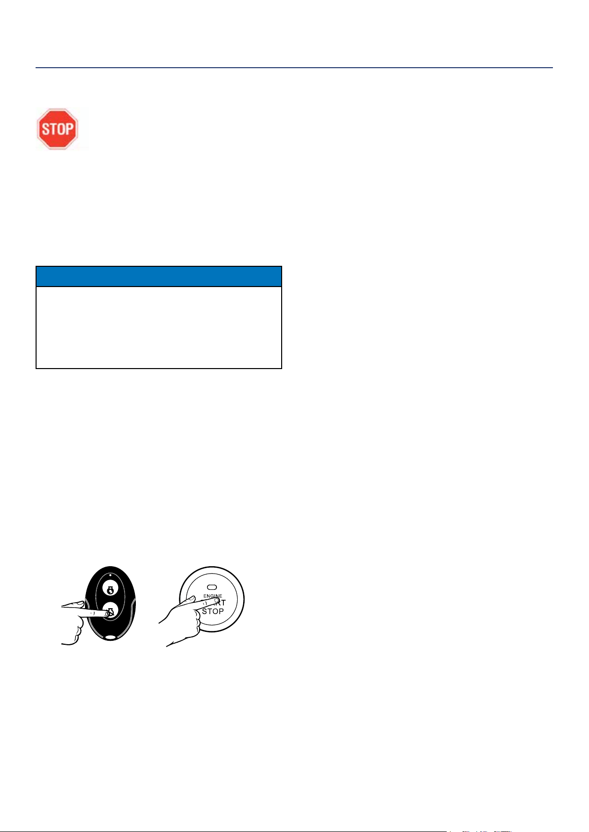
REMOTE START
PUSH BUTTON
ELECTRIC START
2 | Westinghouse Portable Power
DISCLAIMERS:
All information, illustrations and specications in this manual are based on the latest information available at
the time of publishing. The illustrations used in this manual are intended as representative reference views only.
Moreover, because of our continuous product improvement policy, we may modify information, illustrations and/or
specications to explain and/or exemplify a product, service or maintenance improvement. We reserve the right
to make any change at any time without notice. Some images may vary depending upon which model is shown.
ALL RIGHTS RESERVED:
No part of this publication may be reproduced or used in any form by any means – graphic, electronic or
mechanical, including photocopying, recording, taping or information storage and retrieval systems – without the
written permission of MWE Investments LLC.
DANGER
This manual contains important instructions for operating this generator. For your safety and the safety of others, be sure
to read this manual thoroughly before operating the generator. Failure to properly follow all instructions and precautions
can cause you and others to be seriously hurt or killed.
TABLE OF CONTENTS
TECHNICAL SPECIFICATIONS ..................3
PRODUCT REGISTRATION .....................3
For Your Records: .........................3
Product Registration .......................3
Product Registration Form ...................3
SAFETY .....................................4
Safety Denitions ..........................4
Safety Symbol Denitions ....................4
General Safety Rules ........................5
Fuel Safety ...............................6
Safety Labels and Decals ....................7
UNPACKING
Package Contents ..........................8
ASSEMBLY ..................................9
Hooking Up the Battery ......................9
FEATURES ..................................10
Basic Inverter Features .....................10
Control Panel Features ......................11
OPERATION .................................12
Before Starting the Inverter ...................12
Grounding the Inverter ....................12
High Altitude Operation ...................12
Power Cord ...............................13
Inverter Paralleling Operation .................13
Initial Oil Fill ...............................14
Adding/Checking Engine Fluids and Fuel ........15
Connecting the LPG/Propane Tank .............15
Starting the Inverter .........................16
Switching Fuel Sources ......................17
Stopping the Inverter ........................17
Using Eciency Mode ......................17
Resetting the Reset Breaker ..................17
Transporting the Generator ...................18
Power Output and Demand ..................18
MAINTENANCE ..............................19
Maintenance Schedule ......................20
Checking Engine Oil ........................20
Adding Engine Oil ..........................20
Changing Engine Oil ........................20
Air Filter Maintenance .......................21
Draining the Float Bowl ......................22
Spark Plug Maintenance .....................22
Cleaning the Spark Arrestor ..................23
Checking and Adjusting Valve Lash ............23
Cleaning the Inverter ........................24
Battery Service ............................24
Storage ..................................25
TROUBLESHOOTING .........................25
EXPLODED AND ENGINE VIEWS ................27
iGen4500DF Schematic .....................27
iGen4500DF Exploded View ..................28
iGen4500DF Engine View ....................30
NOTICE
This inverter is NOT equipped with altitude carburetor modication. Even with a carburetor modication, engine horsepower will
decrease about 3.5% for each 300 meter (1,000 foot) increase in altitude. The eect of altitude on horsepower will be greater if no
carburetor modication is made. A decrease in engine horsepower will decrease the power output of the generator. Contact our
service team to order altitude kits.
Operating, servicing and maintaining this equipment can expose you to chemicals including engine exhaust,
carbon monoxide, phthalates, and lead, which are known to the State of California to cause cancer and birth
defects or other reproductive harm. To minimize exposure, avoid breathing exhaust, do not idle the engine
except as necessary, service your equipment in a well-ventilated area and wear gloves or wash your hands
frequently when servicing your equipment. For more information go to www.P65Warnings.ca.gov.
WARNING

Westinghouse Portable Power | 3
FOR YOUR RECORDS:
Date of Purchase:
Inverter Model Number:
Purchased from Store/Dealer:
Inverter Serial Number:
IMPORTANT: KEEP YOUR PURCHASE RECEIPT TO ENSURE TROUBLE-FREE WARRANTY
COVERAGE.
PRODUCT REGISTRATION
To ensure trouble-free warranty coverage, it is important you register your Westinghouse inverter.
You can register your generator by either:
1. Filling in the product registration form below and mailing to:
Product Registration
MWE Investments LLC
777 Manor Park Drive
Columbus, Ohio 43228
2. Registering your product Online at www.westinghouseportablepower.com/register-your-product/
To register your generator you will need to locate the following information:
• Model Info Decal located on side panel.
• Serial Number.
WESTINGHOUSE PRODUCT REGISTRATION FORM
PERSONAL INFORMATION INVERTER INFORMATION
First Name: _______________________________________ Model Number: _____________________________________
Last Name: _______________________________________ Serial Number: ______________________________________
Street Address: ___________________________________ Date Purchased: ____________________________________
Street Address: ___________________________________ Purchased From: ____________________________________
City, State, ZIP: ____________________________________
Country: __________________________________________
Phone Number: ___________________________________
E-Mail: ___________________________________________
Model
Running
Watts
Gas/LPG
Peak
Watts
Gas/LP
Fuel Tank
Size (G/L)
Rated
Speed
(RPM)
Ignition
Type
Spark
plug
Engine
Disp
(cc)
Stroke
X Bore
Oil
Cap.
(L) Oil Type THD
Mobile
App
Ready
iGen4500DF 3700/
3330
4500/
4050
3.4/13 3600 TCI F7RTC 224 70X58 0.60 10W30 <3% No
iGen4500DF TECHNICAL SPECIFICATIONS
4 | Westinghouse Portable Power
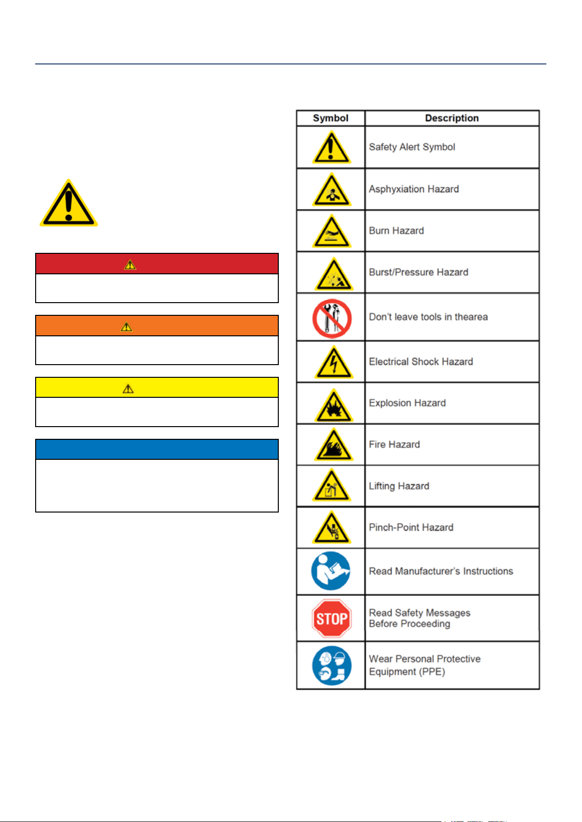
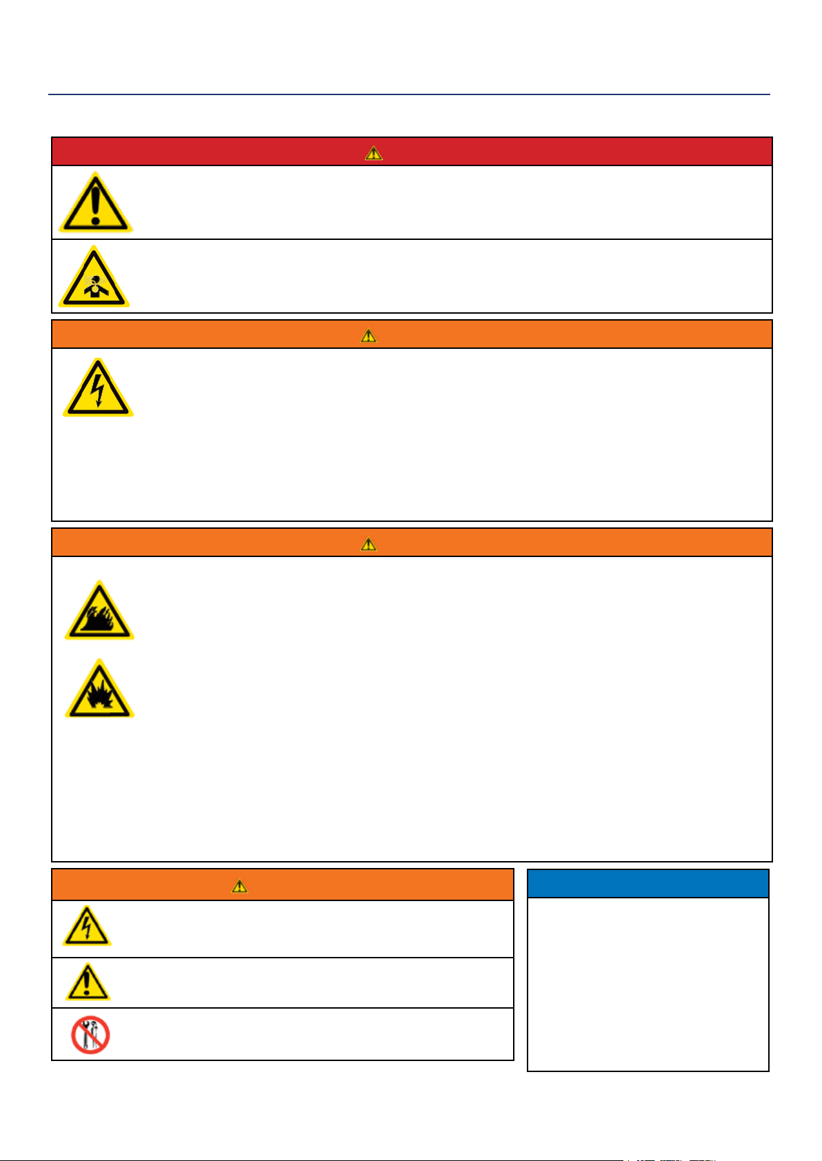
SAFETY DEFINITIONS
The words DANGER, WARNING, CAUTION and
NOTICE are used throughout this manual to highlight
important information. Be certain that the meanings of
these alerts are known to all who work on or near the
equipment.
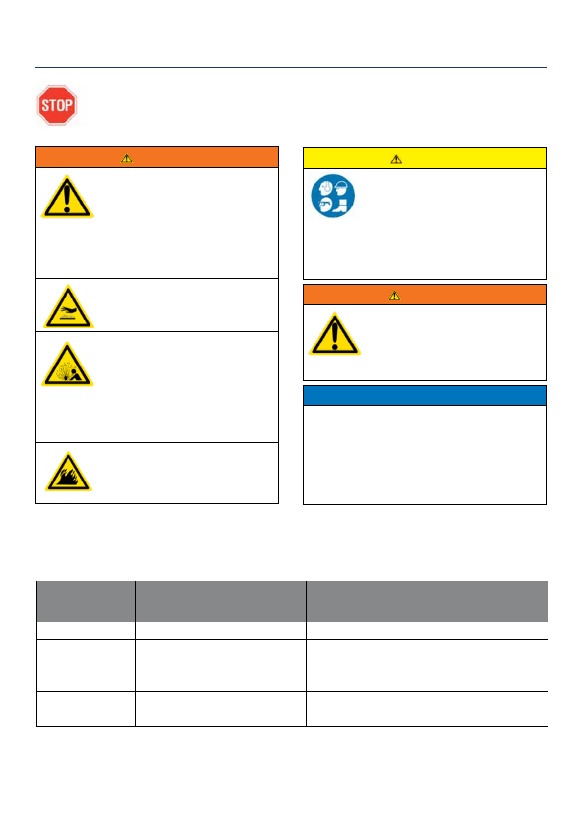
This safety alert symbol appears
with most safety statements. It
means attention, become alert, your
safety is involved! Please read and
abide by the message that follows
the safety alerts symbol.
DANGER
Indicates a hazardous situation which, if not
avoided, will result in death or serious injury.
WARNING
Indicates a hazardous situation which, if not
avoided, could result in death or serious injury.
CAUTION
Indicates a hazardous situation which, if not
avoided, could result in minor or moderate injury.
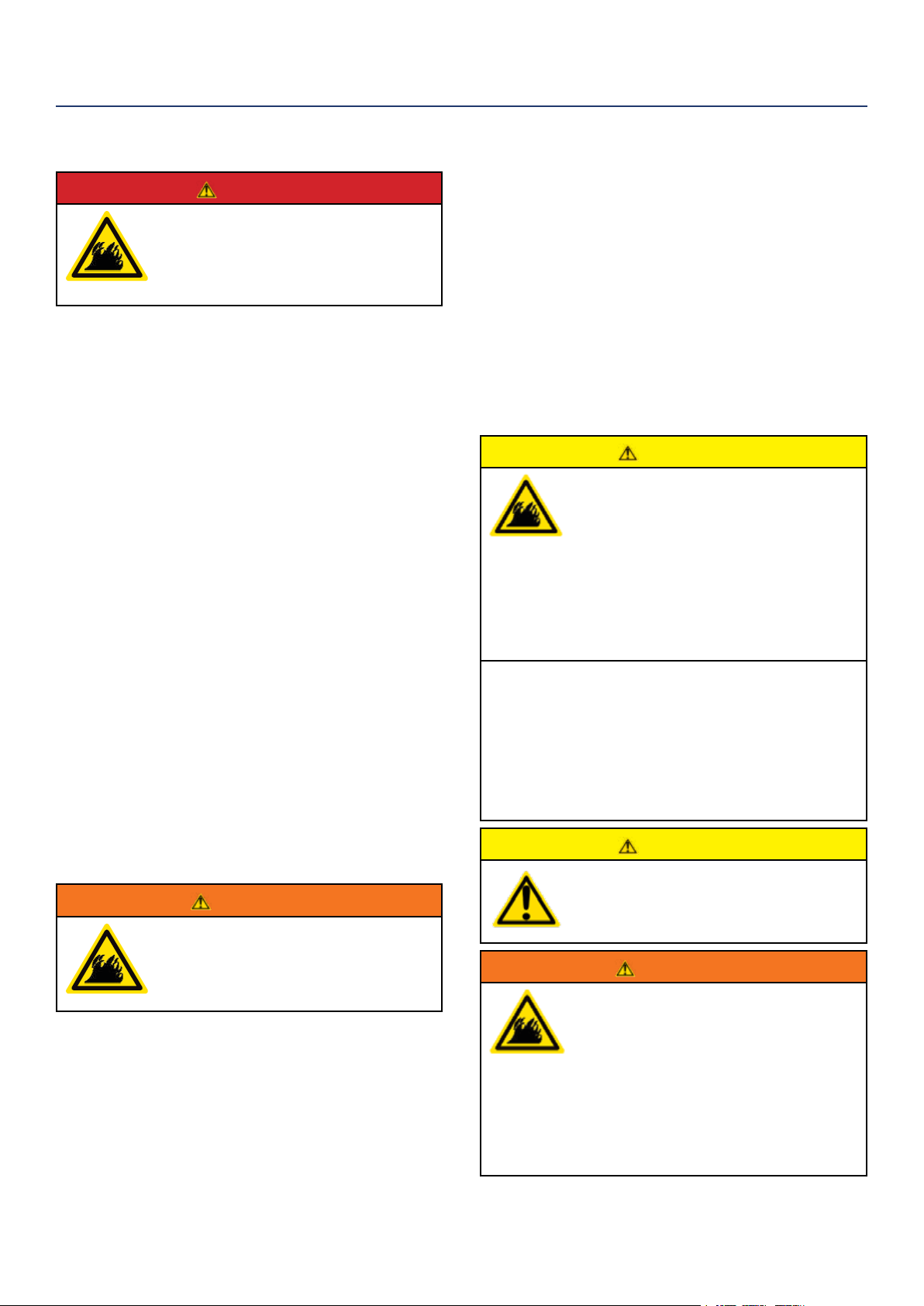
NOTICE
Indicates a situation which can cause damage
to the generator, personal property and/or the
environment, or cause the equipment to operate
improperly.
NOTE: Indicates a procedure, practice or condition
that should be followed in order for the
generator to function in the manner
intended.
SAFETY
SAFETY SYMBOL DEFINITIONS
Westinghouse Portable Power | 5
SAFETY
DANGER
Never use the inverter in a location that is wet or damp. Never expose the inverter to rain, snow,
water spray or standing water while in use. Protect the inverter from all hazardous weather
conditions. Moisture or ice can cause a short circuit or other malfunction in the electrical circuit.
Never operate the inverter in an enclosed area. Engine exhaust contains carbon monoxide. Only
operate the inverter outside and away from windows, doors and vents.
WARNING
Voltage produced by the inverter could result in death or serious injury.
• Never operate the inverter in rain or a ood plain unless proper precautions are taken to avoid
being subject to rain or a ood.
• Never use worn or damaged extension cords.
• Always have a licensed electrician connect the inverter to the utility circuit.
• Never touch an operating inverter if the inverter is wet or if you have wet hands.
• Never operate the inverter in highly conductive areas such as around metal decking or steel works.
• Always use grounded extension cords. Always use three-wire or double-insulated power tools.
• Never touch live terminals or bare wires while the inverter is operating.
• Be sure the inverter is properly grounded before operating.
WARNING
Gasoline, gasoline vapors & liquid petroleum gas (LPG) are extremely ammable and explosive
under certain conditions.
• Always refuel the inverter outdoors, in a well-ventilated area.
• Never remove the fuel cap with the engine running.
• Never refuel the inverter while the engine is running. Always turn engine o and allow the inverter
to cool before refueling.
• Only ll fuel tank with gasoline.
• Keep sparks, open ames or other form of ignition (such as matches, cigarettes, static electric
sources) away when refueling.
• Never overll the fuel tank. Leave room for fuel to expand. Overlling the fuel tank can result in a
sudden overow of gasoline and result in spilled gasoline coming in contact with HOT surfaces.
Spilled fuel can ignite. If fuel is spilled on the inverter, wipe up any spills immediately. Dispose of
rag properly. Allow area of spilled fuel to dry before operating the inverter.
• Wear eye protection while refueling.
• Never use gasoline as a cleaning agent.
• Store any containers containing gasoline or propane in a well-ventilated area, away from any
combustibles or source of ignition.
• Check for fuel leaks after refueling. Never operate the engine if a fuel leak is discovered.
WARNING
Never operate the inverter if powered items overheat,
electrical output drops, there is sparking, ames or smoke
coming from the inverter, or if the receptacles are damaged.
Never use the inverter to power medical support equipment.
Always remove any tools or other service equipment used
during maintenance from the inverter before operating.
NOTICE
Never modify the inverter.
Never operate the inverter if it
vibrates at high levels, if engine
speed changes greatly or if the
engine misres often.
Always disconnect tools or
appliances from the
generator before starting.
GENERAL SAFETY RULES
6 | Westinghouse Portable Power
When transporting or servicing the generator:
• Make certain the fuel shuto valve is o and the fuel
tank is empty.
• Make sure the LPG tank and LPG hose is not attached
to the generator.
• Disconnect the spark plug wire.
When storing the generator:
• Store away from sparks, open ames, pilot lights, heat
and other sources of ignition.
• Do not store gas or LPG tank near furnaces, water
heaters or any other appliances that produce heat or
have automatic ignitions.
CAUTION
Only use approved LPG tanks with OPD
(overlling prevention device) valve. Always
keep the tank in a vertical position with the
valve on top and installed at ground level
on a at surface. Do not allow tanks to be
around any heat source and make sure it is
not exposed to the sun, rain and dust. When
transporting and storing, turn o the tank
valve and fuel valve, and disconnect the tank.
Make sure to always cover the generator and
tank outlet with protective plastic caps.
Large (500-1000 gallon) LPG tanks will
require a certied plumber to install the fuel
line to the generator and the loose regulator
is not used (the regulator that is attached to
the fuel tank). The pressure as measured at
the regulator mounted to the generator must
be 7” to 14” of water column. The plumber
will ensure that the pressure is correct or
install a step down regulator if needed.
CAUTION
Do not allow children to tamper or play with
the propane tank or hose connections.
WARNING
If there is a strong smell of propane while
operating the generator close the valve on
the propane tank immediately. Once the
propane is o, use soapy water to check for
leaks on the hose and connections on the
tank valve and the generator. Do not smoke
or light a cigarette or check for leaks using
any open ame source such as a match or
lighter. If a leak is found contact a qualied
technician to inspect and repair the LPG
system before using the generator.
DANGER
Gasoline and liquid petroleum gas
(LPG) are highly explosive and
ammable. Explosions and re can
cause severe burns or death.
Gasoline and gasoline vapor (Gas)
• Gasoline is highly ammable and explosive.
• Gas expands and contracts with dierent
temperatures.
• In case of a gas re, do not attempt to extinguish the
ame if the fuel shuto valve is in the on position.
Introducing an extinguisher to a generator with an
open fuel valve could create an explosion hazard.
• Gas has a distinctive odor, this will help detect
potential leaks quickly.
• Gas vapors can cause a re if ignited.
• Gasoline is a skin irritant and needs to be cleaned up
immediately if it comes in contact with the skin.
Liquid Petroleum Gas (Propane/LPG)
• LPG/Propane is highly ammable and explosive.
• Flammable gas under pressure can cause a re or
explosion if ignited.
• LPG/Propane can settle in low places because it is
heavier than air.
• LPG/Propane has a distinctive odor added to help
detect potential leaks.
• Always keep LPG/Propane tank in an upright position.
• When exchanging LPG/Propane tanks, be sure the
tank value is the same type.
• In case of a LPG/Propane re, do not attempt to
extinguish unless the fuel supply can be shut o.
• LPG/Propane will burn the skin. Prevent skin contact
at all times.
WARNING
Never use a gas container, LPG
connector hose, LPG tank or any
other fuel item that appears to be
damaged.
When starting generator:
• Make sure that the gas cap, air lter, spark plug, fuel
lines and exhaust system are properly in place.
• If you spill any gasoline on the tank, allow it to fully
evaporate before operating.
• Make sure the generator and propane tank are on a
at surface before operating.
• If there is a propane odor do not start the unit because
there may be a potential leak.
• Never place propane tank near engine exhaust.
SAFETY
FUEL SAFETY
Westinghouse Portable Power | 7
278mm * 29mm
MANUAL START ELECTRIC START REMOTE START
GASOLINE
SET UP
PROPANE
SET UP
START
Make sure connections are
safely secure
START
STOP
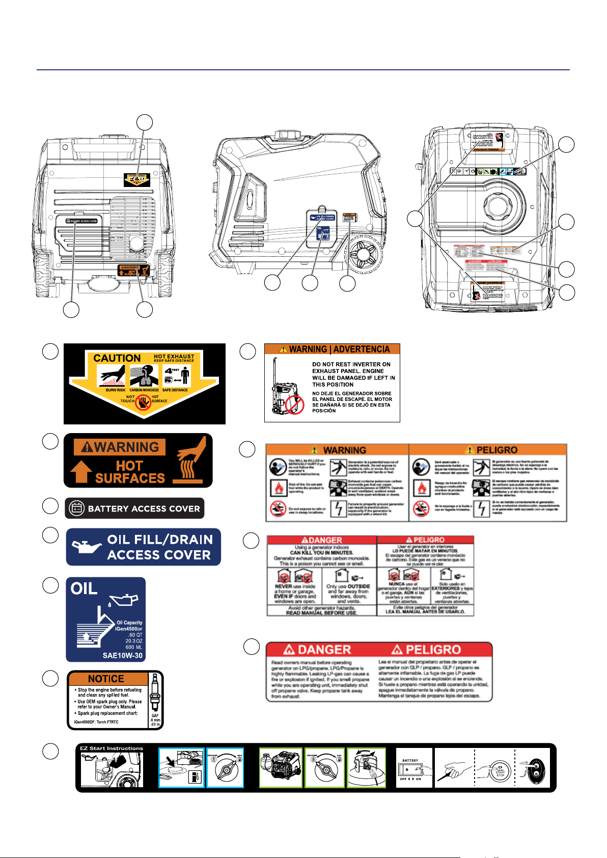
SAFETY
SAFETY LABELS AND DECALS
1
1
2
3
4
5
6
8
9
2
3
5
4
6
10
11
7
8
11
9
10
7
278mm * 29mm
MANUAL START ELECTRIC START REMOTE START
GASOLINE
SET UP
PROPANE
SET UP
START
Make sure connections are
safely secure
START
STOP
8 | Westinghouse Portable Power
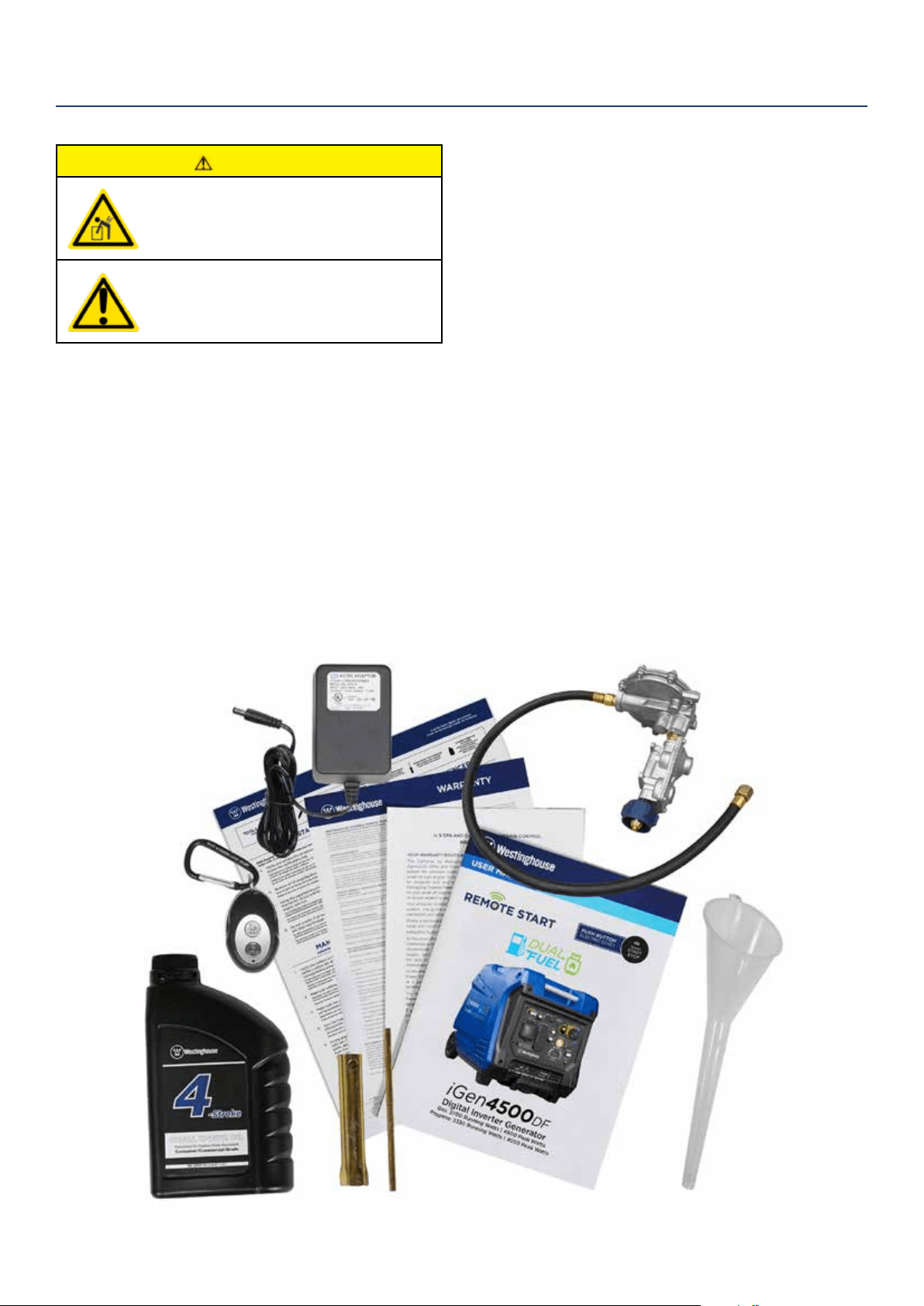
WHAT COMES IN THE BOX
Manual
Quick Start Guide/Maintenance Schedule
LPG Hose with regulator (1)
Wireless Remote Starter (1)
.6 Liter Bottle of SAE 10W30 Oil (1)
Battery Charger (1)
Spark Plug Socket Wrench (1)
Wheel Kit Accessories Box
Oil Funnel (1)
If any parts are missing, contact our service team at
[email protected] or call 1-855-944-3571.
CAUTION
Always have assistance when lifting
the generator. The generator is heavy;
lifting it could cause bodily harm.
Avoid cutting on or near staples
to prevent personal injury.
Tools required – box cutter or similar device.
1. Carefully cut the packing tape on top of the carton.
2. Fold back top aps to reveal the upper packing
tray.
3. Remove and save the instruction manual, oil bottle,
oil funnel, LPG hose, spark plug socket wrench &
battery charger.
4. Remove and discard the upper packing tray.
5. Unfold the top of the plastic bag enclosing the
generator.
6. Carefully cut the vertical corners of the carton to
access the generator.
7. Recycle or dispose of the packaging materials
properly.
UNPACKING

Westinghouse Portable Power | 9
HOOKING UP THE BATTERY
WARNING
To avoid electrics hock:
• ALWAYS connect the positive (+)
battery cable (red boot) rst when
connecting battery cables.
• ALWAYS disconnect the negative (-)
battery cable (black boot) rst when
disconnecting battery cables.
• NEVER connect the negative (-)
battery cable (black boot) to the
positive (+) post on the battery.
• NEVER connect the positive (+)
battery cable (red boot) to the
negative (-) post on the battery.
• NEVER touch both battery posts
simultaneously.
• NEVER place a metal tool across
both battery posts.
• ALWAYS use insulated or
nonconducting tools when installing
the battery.
NOTE: THE INVERTER COMES EQUIPPED WITH
THE POSITIVE BATTERY CABLE (RED BOOT)
ALREADY ATTACHED.
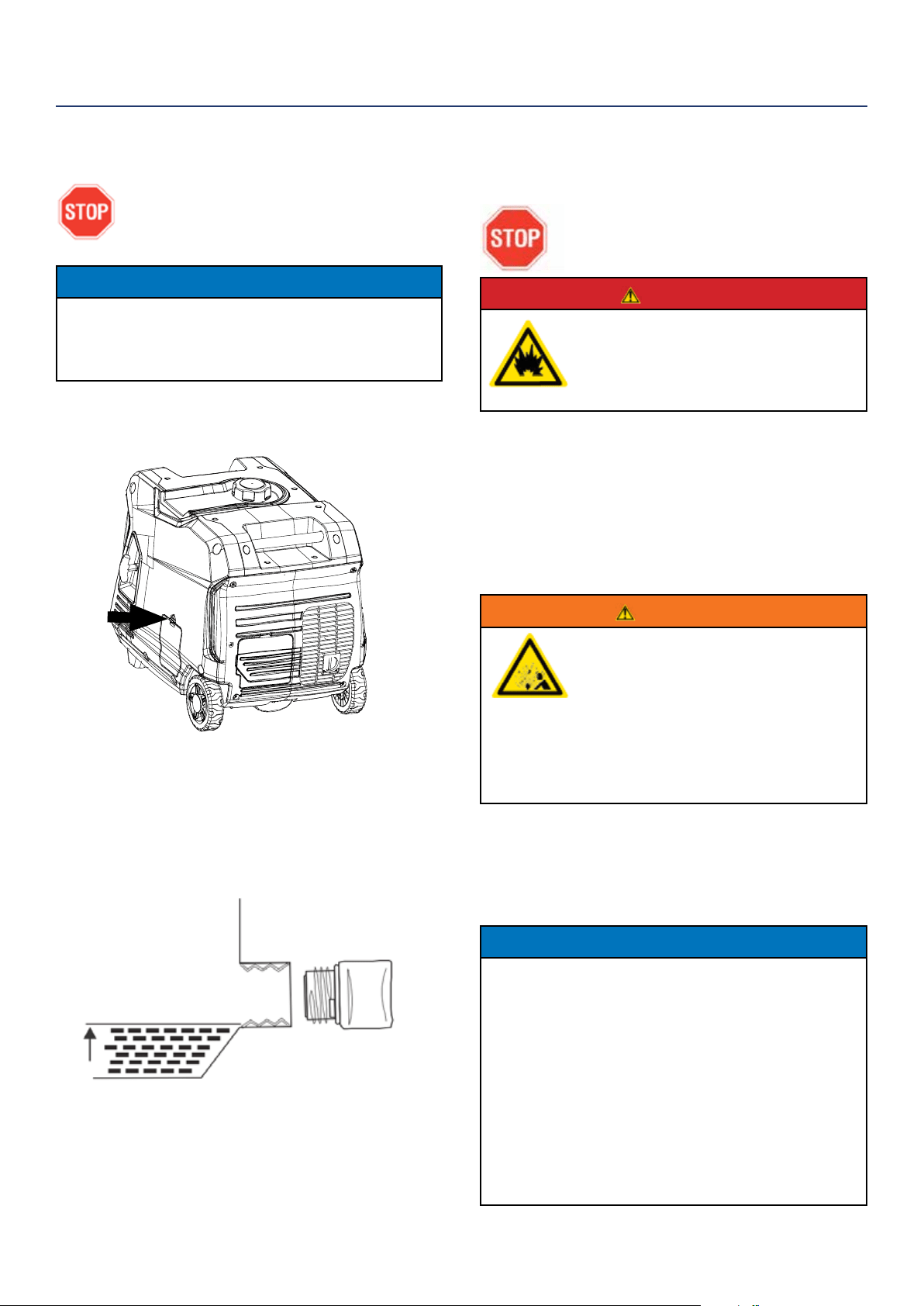
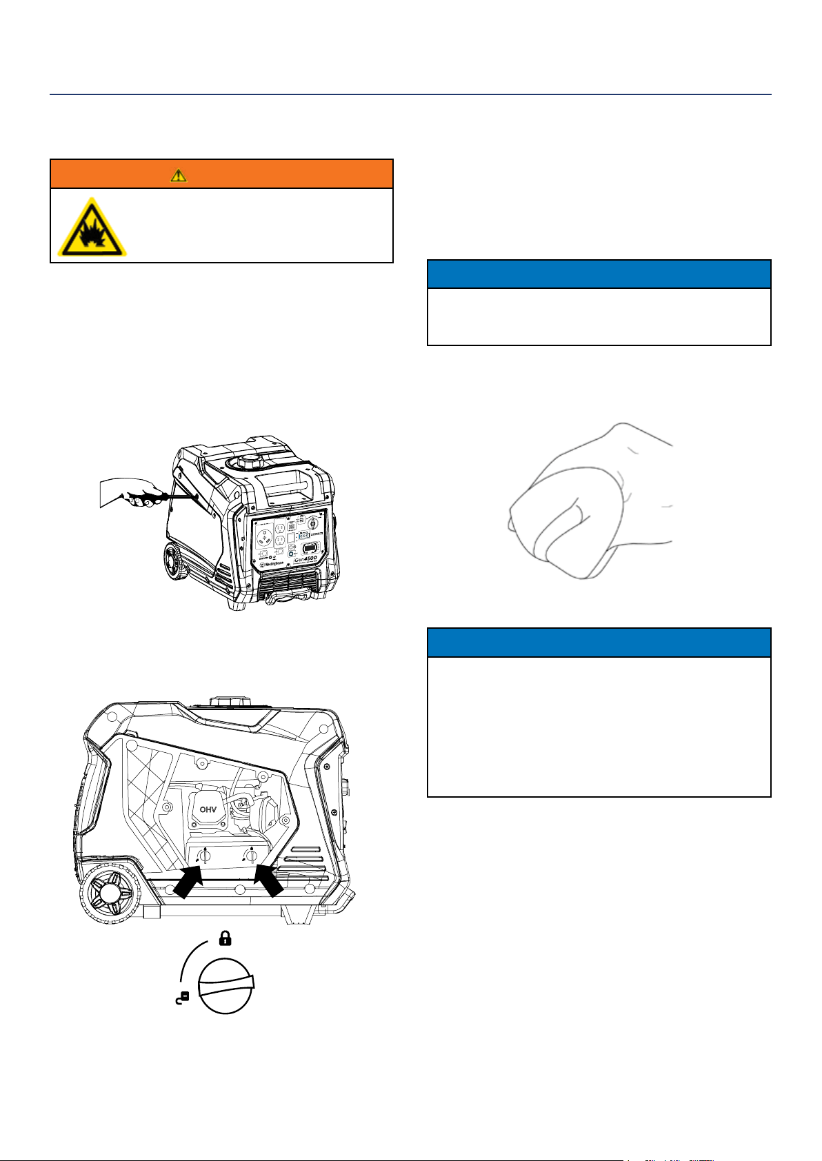
1. Unclip the battery access panel on the back of the
unit next to the muer (see Figure 1).
Figure 1: Battery service panel
2. Pull down on the battery strap clip and unhook it
from the mounting base.
3. Lift the battery up, withdraw it bottom-rst through
the battery access port and then stand it up
vertically in its normal orientation.
4. Clip the battery quick connect from the battery
leads to the main lead inside the inverter (see image
above).
5. Verify the positive (+) battery cable (red boot) is
securely tightened to the positive (+) battery post.
Make sure boot is over battery post.
Figure 2: Installing battery leads
Positive
(Red)
Negative
(Black)
6. Insert the battery top-rst through the battery
access port and stand it up vertically on its
mounting base.
7. Check that the battery is positioned correctly and
that the battery cables are not kinked or pinched.
8. Pass the battery strap under the negative (-) battery
cable and centrally over the top of the battery. Then
pull down on the battery strap clip and hook it onto
the mounting base.
9. Replace the battery access cover.
NOTE: The electric start generator is equipped
with a battery charging feature. Once the engine is
running, a small charge is supplied to the battery
via the battery cables and will slowly recharge the
battery.
ASSEMBLY
10 | Westinghouse Portable Power
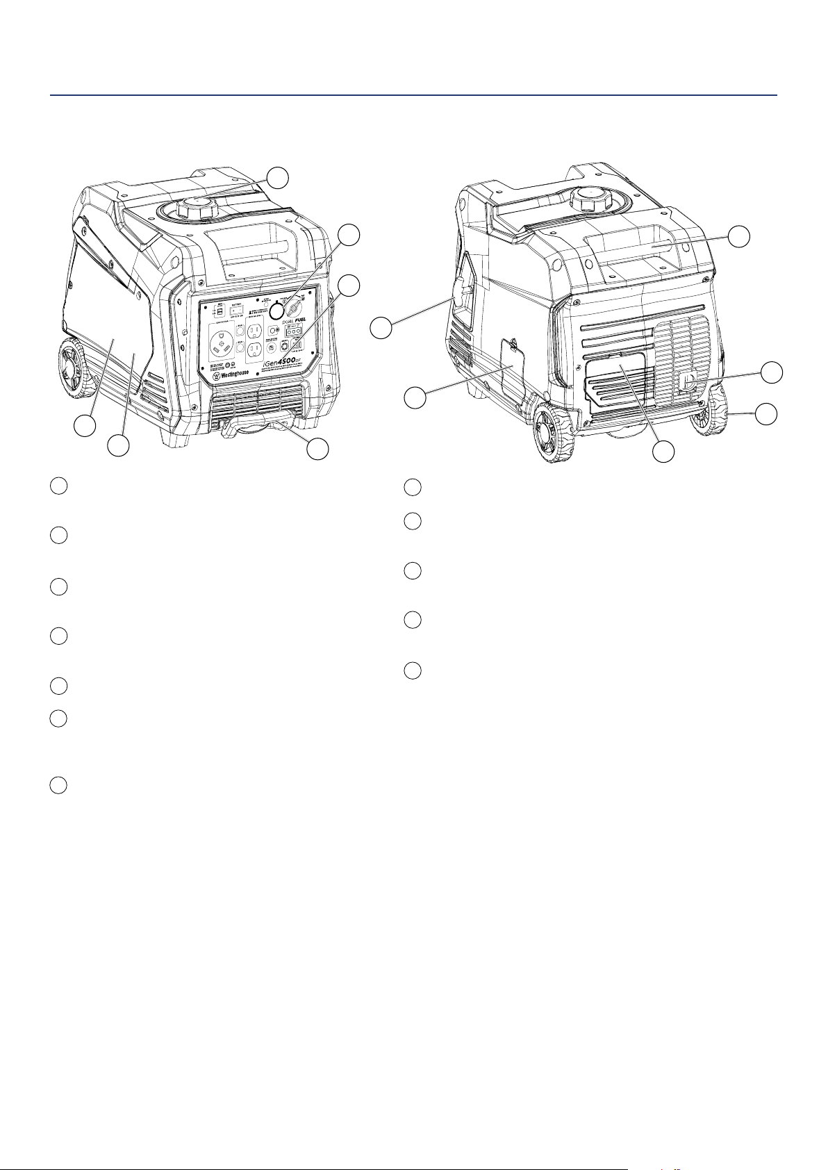
Propane Hook Up: Hook up your propane tank
with the LPG hose provided to this inlet.
Control Panel: Contains the reset breaker,
outlets and warning lights.
Oil Access Cover: Remove the cover to
access the oil ll/drain plug.
Recoil Handle: Pull to manually start the
engine.
Fuel Cap: Close until clicking sound is heard.
Engine Service Panel: Remove the panel to
access the engine, choke, air lter, spark plug
and oat bowl for maintenance.
Muer and Spark Arrestor: Avoid contact
until the engine is cooled down. The spark
arrestor prevents sparks from exiting the
muer. It must be removed for servicing.
FEATURES
BASIC INVERTER FEATURES iGen4500DF
1
5
6
7
8
9
10
11
12
2
3
4
Roller Board Wheels: For easy portability.
Telescoping Handle: Extends and retracts for
easy access.
Carry Handles: Built in handles to allow for
easy pick up.
Battery Access Panel: Easy access to
battery.
Automatic Choke: Unit will automatically set
choke for electric and manual start (if battery
is dead or disconnected you may have to set
choke manually).
1
2
3
4
5
6
12
7
8
9
10
11
Westinghouse Portable Power | 11
BC
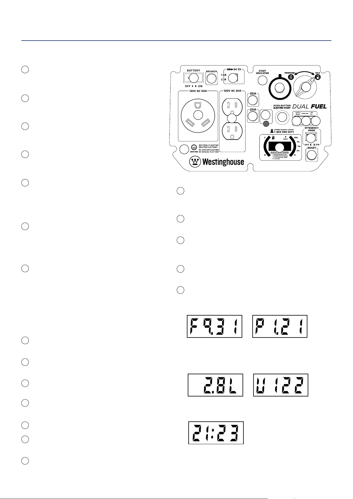
120-Volt, 20-Amp Duplex Outlet (NEMA 5-20R):
The outlet is capable of carrying a maximum of 20
amps.
120-Volt 30 Amp TT-30 Outlet: Travel Trailer
outlet can supply a maximum of 30 amps and
120 volts.
20-Amp Circuit Breaker: Each circuit breaker
limits the current that can be delivered through
the 120-volt duplex outlets to 20amps.
30-Amp Circuit Breaker: Each circuit breaker
limits the current that can be delivered through
the 120-volt TT-30 outlets to 30amps.
USB Duplex: 5V DC USB outlets that come with
1 and 2.1 amp rating. 5-Volt DC USB devices or
extension cords must be tted with a standard
Type “A” USB male plug for connection to the
generator
Reset Breaker: If the inverter is overloaded, the
reset breaker will trip. The engine will continue to
run, but there will be no output from the inverter.
Unplug the devices and reduce the load. Push in
the reset breaker to reset it.
Eciency Mode Switch: Move the switch to the
ON position when powering small resistive loads
such as a computer or electric light; the engine
speed will automatically be kept to a minimum,
thereby reducing fuel consumption and noise.
Select the OFF position when powering large
inductive loads such as an air conditioner or
electric pump; the engine speed will be kept
higher for maximum electrical starting power.
Ground Terminal: The ground terminal is used to
externally ground the inverter.
Battery Switch: Turns battery on and o. Must be
on before electric start.
Output Ready LED: Indicates the inverter is
ready to be used.
Overload LED: Indicates that the inverter is
overloaded.
Low Oil LED: Indicates low oil level.
Battery Charging Port: Used to charge battery
when unit is o.
Main Circuit Breaker: The main circuit breaker
controls total output of all outlets to protect the
generator.
Fuel Selector Switch: Select and turn on gas or
propane. You cant switch fuel sources while unit is
running.
Start Indicator: Indicates that power is on, light
will remain lit the whole time the unit is on.
Push Button Automated Start: Push once to
automatically start the engine. Push again to
stop the engine.
Propane Hook Up: Hook up your propane tank
with the LPG hose provided to this inlet.
LED Data Center: Displays remaining run time
(F), power output in kW (P), fuel level in liters (L),
voltage (V), and lifetime hours.
FEATURES
CONTROL PANEL FEATURES iGen4500DF
1
2
3
4
5
6
7
8
9
11
12
13
14
15
16
17
18
19
10
15
16
1
2
3
4
6
8
9
10 11 12
13
14
7
5
17
18
19
Remaining Run Time:
Displays time remaining
with current fuel level and
power output. Does not
display lifetime hours.
Power Output:
Displays electrical power
output to receptacles in
kilowatts.
Fuel level:
Displays current fuel
level in liters.
Voltage:
Displays current voltage
output of generator.
Lifetime Hours:
Displays the total run
time of the generator.
12 | Westinghouse Portable Power
Weather – Never operate your inverter outdoors during
rain, snow or any combination of weather conditions that
could lead to moisture collecting on, in or around the
generator.
Dry Surface – Always operate the inverter on a dry
surface free of any moisture.
No Connected Loads – Make sure the inverter has no
connected loads before starting it. To ensure there are no
connected loads, unplug any electrical extension cords
that are plugged into the control panel receptacles.
NOTICE
Starting the inverter with loads already applied to
it could result in damage to any appliance being
powered o the inverter during the brief start-up
period.
Grounding the iGen Inverters
Consult with your local municipalities for your
grounding codes.
WARNING
Be sure the inverter is properly
connected to earth ground before
operating.
High Altitude Operation
Engine power is reduced the higher you operate above
sea level. Output will be reduced approximately 3.5% for
every 1000ft of increased altitude from sea level. This is
a natural occurrence and cannot be adjusted by engine.
Increased exhaust emissions can also result due to
increased fuel mixture. Other issues include hard starting,
increased fuel consumption and spark plug fouling.
High Altitude Carburetor Kit Part Number: 140540
High Altitude DF Regulator Part Number: 140547
Note: You must purchase the Dual Fuel Regulator along
with carburetor kit for proper high altitude operation.
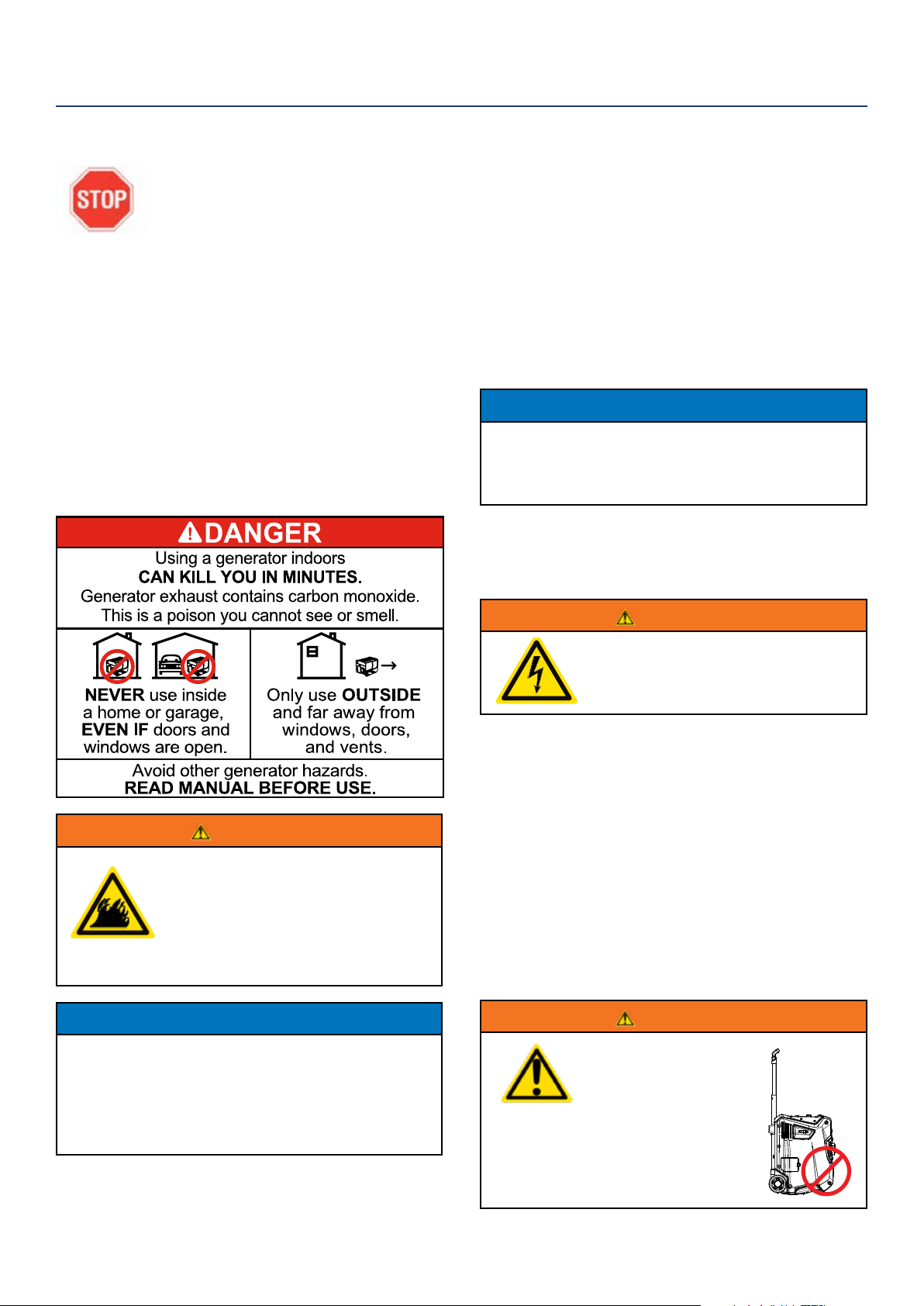
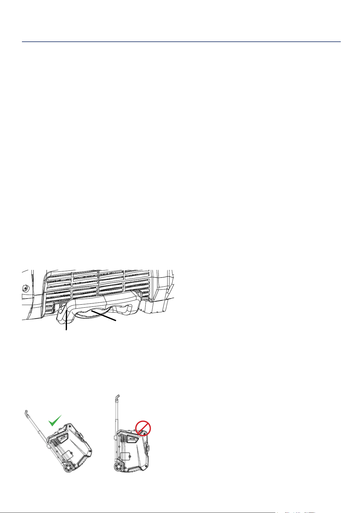
WARNING
Do not rest inverter on
exhaust panel. Do not
move Generator while it
is on. The inverter will
be damaged if operated
in this manner.
BEFORE STARTING THE INVERTER
BEFORE STARTING THE INVERTER,
REVIEW SAFETY SECTION STARTING
ON PAGE 4.
Location Selection – Before starting the inverter, avoid
exhaust and location hazards by verifying:
• You have selected a location to operate the inverter
that is outdoors and well ventilated.
• You have selected a location with a level and solid
surface on which to place the inverter.
• You have selected a location that is at least 6 feet
(1.8 m) away from any building, other equipment or
combustible material.
• If the inverter is located close to a building, make
sure it is not located near any windows, doors and/
or vents.
WARNING
Always operate the inverter on a level
surface. Placing the inverter on non
level surfaces can cause the inverter
to tip over, causing fuel and oil to spill.
Spilled fuel can ignite if it comes in
contact with an ignition source such
as a very hot surface.
NOTICE
Only operate the inverter on a solid, level surface.
Operating the inverter on a surface with loose
material such as sand or grass clippings can cause
debris to be ingested by the inverter that could:
• Block cooling vents
• Block air intake system
OPERATION
Westinghouse Portable Power | 13
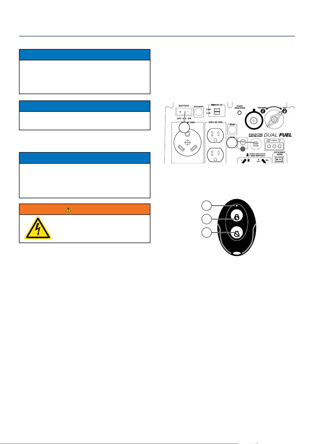
If the key fob is replaced or needs to be reconnected,
you will need to go through this procedure with the new
fob.
1. Turn the battery switch to the ON position.
2. Press and hold the electric start button on the
control panel of the generator for 10s, then let go,
and the start indicator light will ash green.
BC
1
2
3. Press the start button on remote fab, and it will
pair with generator automatically. Then the start
indicator light on the generator will stop ashing.
4. Start the unit.
START
STOP
1
2
3
Remote Start Key Fob
1 - Pairing Indicator light
2 - Start Button | 3 - Stop Button
NOTICE
During the rst ve hours of operating the generator make sure to
not exceed 50% of the rated running watts until the unit is broken
in properly. Make sure to vary to load occasionally to allow stator
windings to heat and cool. Adjusting the load will also help seat
piston rings. Check oil more often during the rst couple times of
operating the generator.
NOTICE
Weather will aect engine oil performance. Change the type of
engine oil used based on weather conditions to suit the engine
needs.
PROGRAMMING THE GENERATOR FOR
REMOTE START
NOTICE
The key fob included with the generator should come
already paired with the unit. If it does not you can
follow the directions below to reconnect. If your unit
was shipped without a key fob please contact our
customer support team.
WARNING
Always make sure the area around
the generator is clear of bystanders
before using the remote start to start
the generator.
The generator can be started remotely from up to a
maximum of 109 yards (100 M) away using the remote
start key fob with new, fully charged batteries in the
key fob. As the batteries’ state of charge in the key fob
reduces, the distance to start the generator will also
reduce.
OPERATION
14 | Westinghouse Portable Power
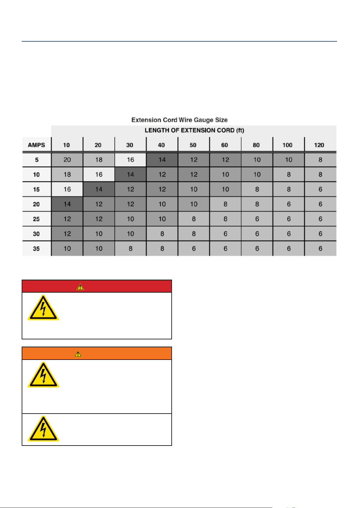
POWER CORD
Using Extension Cords
Westinghouse Portable Power assumes no responsibility for the content within this table. The use of this table is the
responsibility of the user only. This table is intended for reference only. The results produced by using this table are
not guaranteed to be correct or applicable in all situations as the type and construction of cords are highly variable.
Always check with local regulations and a licensed electrician prior to installing or connecting an electrical appliance
INVERTER PARALLELING OPERATION
DANGER
Never connect the paralleling cord
to the inverters with the inverters
running. The inverters must not be
running and both the paralleling cord
switches must be o when connecting
the cords.
WARNING
Do not attempt to parallel the
Westinghouse inverter with any other
manufacturers’ inverters. Do not use
the paralleling cord for any application
other than inverter paralleling. Do not
use this cord on other manufacturers’
inverters.
Always ensure that both ends of
the paralleling cord are switched o
before connecting the inverters.
INVERTER PARALLELING OPERATION
1. Using only the Westinghouse paralleling cord with
both cord switches set to OFF (O), connect one
male plug to one inverter and connect the remain-
ing plug into the other inverter. Either of the recep-
tacles on the inverters can be used.
2. Start one of the inverters and wait until the ready
light is on.
3. Turn both cord switches to ON (I).
4. Start the remaining inverter; wait until the ready
light is on before connecting the load.
5. When power is present, a light will illuminate in the
three-prong plug that is plugged into the inverter.
6. To stop the inverters, unplug all connected loads,
turn both cord switches to OFF (O) and unplug the
cord on each inverter.
7. If during operation the inverters’ output is stopped
due to overloading, reduce the connected load by
unplugging appliances, and then push the reset
button and restart the inverter. When the ready light
is on, the load can be reconnected.
OPERATION
Westinghouse Portable Power | 15
INITIAL OIL FILL
BEFORE ADDING ENGINE OIL, REVIEW
SAFETY SECTION STARTING ON PAGE 4.
NOTICE
Engine oil must be added when the inverter is on a
at, level surface, or an inaccurate reading may result.
Do not overll. If the engine is overlled with oil, it can
cause serious engine damage.
1. Unclip and remove the oil service panel to access
the oil ll/drain plug (see Figure 3).
Figure 3: Oil service panel
2. Clean area around oil ll/drain plug and remove
plug.
3. Using the supplied funnel and oil, pour the entire
bottle of oil into the engine. See correct oil level in
Figure 4 below.
Figure 4: Engine oil correct level
4. Do not overll, if oil level is too high, oil will drain
out through the ll plug.
OPERATION
ADDING/CHECKING ENGINE
FLUIDS AND FUEL
BEFORE ADDING/CHECKING ENGINE
FLUIDS AND FUEL, REVIEW SAFETY
SECTION STARTING ON PAGE 4.
DANGER
Filling the fuel tank with gasoline while
the inverter is running can cause
gasoline to leak and come in contact
with hot surfaces that can ignite the
gasoline.
Before starting the inverter, always check the level of:
• Engine oil
• Gasoline in the fuel tank
Once the inverter is started and the engine gets warm,
it is not safe to add gasoline to the fuel tank or engine
oil to the engine while the engine is running or the en-
gine and muer are hot.
CHECKING AND / OR ADDING ENGINE OIL
WARNING
Internal pressure can build in the
engine crankcase while the engine
is running. Removing the oil ll plug/
dipstick while the engine is hot can
cause extremely hot oil to spray out of
the crankcase and can severely
burn skin. Allow engine oil to cool for
several minutes before removing the
oil ll plug/dipstick.
The unit as shipped does not contain oil in the engine.
You must add engine oil before starting the inverter
for the rst time. See Initial Oil Fill for instructions on
checking engine oil level and the procedure for adding
engine oil.
NOTICE
The engine does not contain engine oil as shipped.
Attempting to start the engine without adding
engine oil will permanently damage internal engine
components.
The engine is equipped with a low oil shutdown
switch. If the oil level becomes low, the engine may
shut down and not start until the oil is lled to the
proper level.
The owner of the inverter is responsible to ensure the
proper oil level is maintained during the operation of
the generator. Failure to maintain the proper oil level
can result in engine damage.
16 | Westinghouse Portable Power
ADDING GASOLINE TO THE FUEL TANK
WARNING
Never refuel the inverter while the
engine is running.
Always turn the engine o and allow
the inverter to cool before refueling.
CAUTION
Avoid prolonged skin contact with
gasoline. Avoid prolonged breathing of
gasoline vapors.
Required Gasoline – Only use gasoline that meets the
following requirements:
• Unleaded gasoline only
• Gasoline with maximum 10% ethanol added
• Gasoline with an 87 octane rating or higher
Filling the Fuel Tank – Follow the steps below to ll the
fuel tank:
1. Shut o the inverter.
2. Allow the inverter to cool down so all surface areas
of the muer and engine are cool to the touch.
3. Move the inverter to a at surface.
4. Clean area around the fuel cap.
5. Remove the fuel cap by rotating counterclockwise.
NOTICE
Do not overll the fuel tank. Spilled fuel will damage
some plastic parts.
6. Slowly add gasoline into the fuel tank. Be very care-
ful not to overll the tank. The gasoline level should
NOT be higher than the red ring (see Figure 5).
7. Install the fuel cap by rotating clockwise.
Figure 5: Maximum gasoline ll level
OPERATION
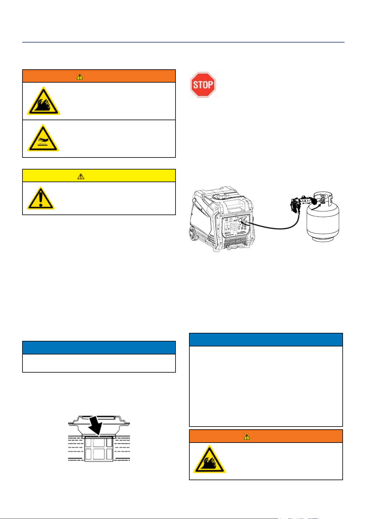
CONNECTING THE LPG/PROPANE TANK
BEFORE CONNECTING PROPANE TANK
TO THE GENERATOR PLEASE REVIEW
FUEL SAFETY SECTION ON PAGE 6
Connecting LPG Tank
1. Make sure the inverter is o, on a at surface in well
ventilated area.
2. Make sure propane tank valve is in the o position.
3. Make sure the fuel selector switch on the inverter
control panel is pointing downward to “Propane”.
4. Remove the plastic cover on the generator propane
inlet valve.
5. Using your ngers tighten the LPG hose (included)
end below to the generator propane inlet. DO NOT
OVER-TIGHTEN 35-88 Ib-in maximum.
6. Attach the other end of the hose to a tank of LPG/
Propane and hand tighten.
7. Check all connections for leaks by wetting the
ttings with soapy water. Anywhere that bubbles
appear or grow indicates a leak in the connection.
If a leak exists at a tting then turn o the tank
valve and tighten the tting. Turn the gas back on
and recheck with soapy water again. If the leak
continues or if the leak is not at a tting then do not
use the generator and contact customer service.
NOTICE
• The LPG tank can be of any capacity but the tank must conform
to the standard as previously listed in Fuel Safety section.
• LPG tanks that use liquid withdrawal system can not be used on
these models.
• Verify the requalication date on the tank has not expired.
• All new tanks must be purged of air and moisture prior to lling.
Used tanks that have not been plugged or kept closed must also
be purged
• The purging process should be done by a LPG supplier. (Tanks
from an exchange supplier should have been purged and lled
properly already)
• Always position the tank so the connection between the valve
and the gas inlet won’t cause sharp bends or kinks in the hose.
WARNING
Do not start generator if you smell propane.
This may result in explosion hazard. Do not use
provided LPG hose for any other appliances.
Always turn o the propane tank and
disconnect LPG hose when not in use.
Westinghouse Portable Power | 17
STARTING THE INVERTER
BEFORE STARTING THE INVERTER,
REVIEW SAFETY SECTION STARTING
ON PAGE 4.
For proper starting and operation of the inverter,
make sure you review the inverter features and their
descriptions in Features section.
Before attempting to start the inverter, verify the
following:
• The engine is lled with engine oil (see Figure 4:
Engine Oil Correct Level).
• The inverter is situated in a proper location (see
Location Selection).
• The inverter is on a dry surface (see Weather and Dry
Surface).
• All loads are disconnected from the inverter (see No
Connected Loads).
• The inverter is properly grounded (see Grounding the
Inverter)
DANGER
Never use the inverter in a location that is wet or
damp. Never expose the inverter to rain, snow,
water spray or standing water while in use. Protect
the inverter from all hazardous weather conditions.
Moisture or ice can cause a short circuit or other
malfunction in the electrical circuit.
Never operate the inverter in an enclosed area.
Engine exhaust contains carbon monoxide.
Only operate the inverter outside and away from
windows, doors and vents.
1. Check oil levels (see Initial Oil Fill)
2. Make sure nothing is plugged into any of the
outlets.
3. Make sure battery is connected (see Hooking Up
the Battery).
4. Make sure the circuit breakers are properly set
(see Figure 6).
1 2
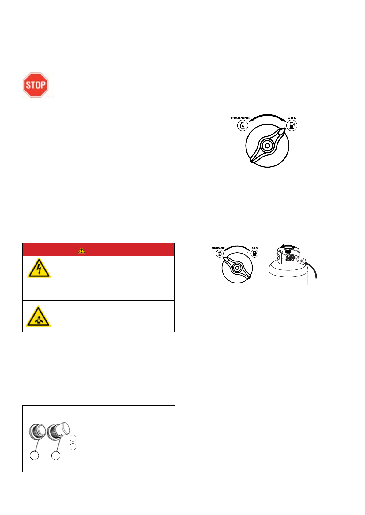
5. Select fuel source for start up:
FOR GASOLINE
a. Make sure there is gas in the tank (see Adding
Gasoline to the Fuel Tank).
b. Turn fuel selector knob to GASOLINE (see
Figure 7).
Figure 7: Turn Fuel selector to GAS position
FOR LPG/PROPANE:
a. Make sure the LPG hose is safely secured from
the generator to the tank (see Connecting the
LPG Tank).
b. Turn the fuel selector knob to PROPANE (see
Figure 8).
c. Fully open the valve on the propane tank.
Figure 8: Turn fuel selector to PROPANE position
Propane tank valve - OPEN
6. Turn battery switch ON.
7. Choose starting method:
a. Recoil Start: Firmly grasp and pull the
recoil handle slowly until you feel increased
resistance. At this point, apply a rapid pull while
pulling up and slightly away from the generator.
b. Remote Start: Click START on the wireless key
FOB provided.
c. Push Button Start: Push and hold the engine
start push button for 1 second and release.
• The engine will automatically set the choke and begin the
start sequence.
• If the engine fails to start, the generator controls will
attempt to start the engine two more times for a total of
three attempts.
• If the engine has failed to start after three attempts the
engine start button can be pushed again to begin the
automatic start sequence.
• The push button can be pushed at any time during
the automatic start sequence to abort the engine start
attempt.
OPERATION
1
2
Figure 6: Breakers
120V Circuit Breaker Operating Position
120V Circuit Breaker Tripped Position
18 | Westinghouse Portable Power
USING EFFICIENCY MODE
The inverter is equipped with an eciency mode switch
to minimize fuel consumption. In eciency mode, the
inverter will sense the load and adjust the engine RPM
to the current load requirements. Eciency mode
should be used only after the inverter has been warmed
up to operating temperature.
1. To turn on the eciency mode, press the switch to
the ON position).
2. If no load is present, the inverter RPM will drop
down to an idle speed.
3. As a load is applied, the inverter will sense the load
and engine RPM will increase according to the load
applied.
4. To run the inverter at maximum power and RPM,
press the eciency mode switch to the OFF
position.
OVERLOAD RESET
An electrical overload or short circuit will trip the
overload protection system by disconnecting the
generator’s AC output even though the engine is still
running. If this occurs, the overload alarm light will be
illuminated red and the output indicator light will be o.
The AC output can be restored as follows:
1. Turn o and unplug any electrical devices or
cords from the 120-Volt AC and 5-Volt DC USB
receptacles on the control panel.
2. Press the generator reset button on the control
panel until the overload alarm light goes o and the
output indicator light is illuminated green.
3. Check that the intended electrical running and
starting loads do not exceed the generator’s
capacity or have a licensed electrician rectify any
fault causing a short circuit in the load.
4. Reconnect any electrical devices or cords to the
receptacles on the control panel and then turn on
the electrical loads as required.
SWITCHING FUEL SOURCES
PLEASE REVIEW FUEL SAFETY
SECTION ON PAGE 6
The below assumes that the propane fuel line is already
attached to the generator securely and safely.
While the unit is running simply turn the FUEL
SELECTOR knob to the desired fuel source. If you
want to switch from gasoline to propane make sure the
propane tank valve is open before you switch. When
you move from propane to gasoline shut the propane
valve after you have switched to gas.
NOTICE
If you do not plan on operating the unit on propane do not leave
the propane tank valve open.
When starting on propane the engine may run rough for a few
seconds while it purges gasoline in the carburetor.
If the engine fails when switching fuel sources simply restart the
unit on the fuel source that you switched to.
STOPPING THE INVERTER
Normal Operation
During normal operation, use the following steps to
stop your inverter:
1. Remove any connected loads from the control
panel receptacles.
2. Allow the inverter to run at “no load” to reduce and
stabilize engine and alternator temperatures.
3. Press and hold the Push Start/Stop Button for 1
second, or press “Stop” on remote start key fob,
(see Figure 9).
4. Switch battery to OFF.
Figure 9: Stopping generator
OPERATION
START
STOP
Westinghouse Portable Power | 19
POWER OUTPUT AND DEMAND
The generator should not be run completely unloaded
for extended periods otherwise the engine may be
damaged. It is recommended that the generator should
always be operated with at least one-third of its rated
120-Volt AC power output. 120-Volt AC devices have
two dierent electric power demands that must be
taken into consideration, namely the running power and
the starting/peak power. Both are measured in Watts
(typically abbreviated as “W”).
The steady state continuous load is the running power
demand and this is often marked on the device near its
model number or serial number. Sometimes the device
might only be marked with its voltage (i.e. 120 V) and
current draw (e.g. 6 Amp or 6 A), in which case the
running power demand in Watts can be obtained by
multiplying the voltage times the current, e.g. 120 V
× 20 A = 2,400 W.
Simple resistive 120-Volt AC devices such as
incandescent bulbs, toasters, heaters, etc. have no extra
power demand when starting, and so their starting power
demands are the same as their running power demands.
More complex120-Volt AC devices containing inductive
or capacitive elements such as electric motors have a
momentary extra power demand when starting, which can
be up to seven times the running power demand or more.
Manufacturers of such devices rarely publish this starting
power demand and so it’s often necessary to estimate it.
A rule of thumb for devices tted with an electric motor is
to apply a starting power multiplier of
1.2 for small hand-held or portable devices and a value
of 3.5 for larger stationary devices. For example, a 900 W
angle grinder can be assumed to have a starting power
demand of at least 1.2 × 900 W, which equals 1,080 W.
Similarly, a 1,650 W air compressor can be assumed to
have a starting power demand of at least 3.5 × 1,650 W,
which equals 5,775 W.
To prevent overloading of the generator’s 120-Volt
AC system:
1. Add up the running power demand of all the 120-Volt
AC devices that will be connected to the generator
at one time. This total must not be greater than the
generator’s specied running power output.
2. Add up the running power demand again, but for
the largest motor-driven device use the value of its
starting power demand instead of its running power
demand. This total must not be greater than the
generator’s specied starting power output.
3. The total running power demand of all the devices
that will be connected to any one of the generator’s
outlets must not exceed the generator’s specied
running power output or 3,700 W, whichever is the
lesser.
TRANSPORTING THE GENERATOR
The generator should be stopped and both the fuel
control switch and fuel cap vent should be turned to the
OFF position before transporting the generator. Keep
the unit level during transport to minimize the possibility
of fuel leakage or, if possible, drain out the fuel prior to
transport.
If the generator has been operating, allow the unit to
cool down before loading it onto the transport vehicle.
The iGen4500’s wheels are only intended for ease of
moving the generator around by hand. The wheels are
not suitable for towing the generator either on or o-
road.
Use only the generator’s xed handle(s) for lifting the
unit or attaching any load restraints such as ropes or
tie-down straps. Do not attempt to lift or secure the
generator by holding onto any of its other components.
The iGen4500 is also equipped with an extendable
handle. To deploy it, push on the locking button and
pull on the handle until it’s fully extended. To stow it,
push on the locking button and push on the handle until
it’s fully retracted. Only extend or retract the handle
while the generator is stationary and resting on a
horizontal surface.
The extendable handle is intended for ease of wheeling
the generator around by hand. Do not use the
extendable handle to lift the generator entirely o the
ground, tow it or up-end it.
OPERATION
Locking Button
Handle Grip
20 | Westinghouse Portable Power
CAUTION
Avoid skin contact with engine oil or
gasoline. Prolonged skin contact with
engine oil or gasoline can be harmful.
Frequent and prolonged contact with
engine oil may cause skin cancer.
Take protective measures and wear
protective clothing and equipment.
Wash all exposed skin with soap and
water.
WARNING
Failure to perform periodic
maintenance or not following
maintenance procedures can cause
the inverter to malfunction and could
result in death or serious injury.
NOTICE
Periodic maintenance intervals vary depending on
inverter operating conditions. Operating the inverter
under severe conditions, such as sustained high-
load, high-temperature, or unusually wet or dusty
environments, will require more frequent periodic
maintenance. The intervals listed in the maintenance
schedule should be treated only as a general
guideline.
WARNING
Avoid accidentally starting the inverter
during maintenance by removing
the spark plug boot from the spark
plug. For electric start inverters, also
disconnect the battery cables from the
battery (disconnect the black negative
(-) cable rst) and place the cables
away from the battery posts to avoid
arcing.
Allow hot components to cool to
the touch prior to performing any
maintenance procedure.
Internal pressure can build in the
engine crankcase while the engine
is running. Removing the oil ll plug/
dipstick while the engine is hot can
cause extremely hot oil to spray out
of the crankcase and can severely
burn skin. Allow engine oil to cool for
several minutes before removing the
oil ll plug/dipstick.
Always perform maintenance in a well-
ventilated area. Gasoline fuel and fuel
vapors are extremely ammable and
can ignite under certain conditions.
MAINTENANCE
BEFORE PERFORMING MAINTENANCE ON THE INVERTER, REVIEW THE
SAFETY SECTION STARTING ON PAGE 4, AS WELL AS THE FOLLOWING
SAFETY MESSAGES.
TABLE 1: MAINTENANCE SCHEDULE - OWNER PERFORMED*
Maintenance Item
Before Every
Use
After First 20
Hours or First
Month of Use
After 50 Hours
of Use or Every
6 Months
After 100 Hour
of Use or Every
6 Months
After 300 Hours
of Use or Every
Year
Engine Oil
Check Level Change Change - -
Cooling Features
Check/Clean - - - -
Air Filter
Check - Clean* - Replace
Spark Plug
- - - Check/Clean Replace
Spark Arrestor
- - - Check/Clean -
Valve Clearance**
- - - Check/Adjust
*Service more frequently if operating in dry and dusty conditions
**Recommend to have service done by authorized Westinghouse service dealer
Following the maintenance schedule is important to keep the inverter in good operating condition. The following is a
summary of maintenance items by periodic maintenance intervals.
Westinghouse Portable Power | 21
ADDING ENGINE OIL
1. Always operate or maintain the inverter on a at
surface.
2. Stop engine if running.
3. Let engine sit and cool for several minutes (allow
crankcase pressure to equalize).
4. Remove the engine service panel to gain access to
the oil ll/drain plug.
5. Thoroughly clean around the oil ll/drain plug.
6. Remove the oil ll/drain plug.
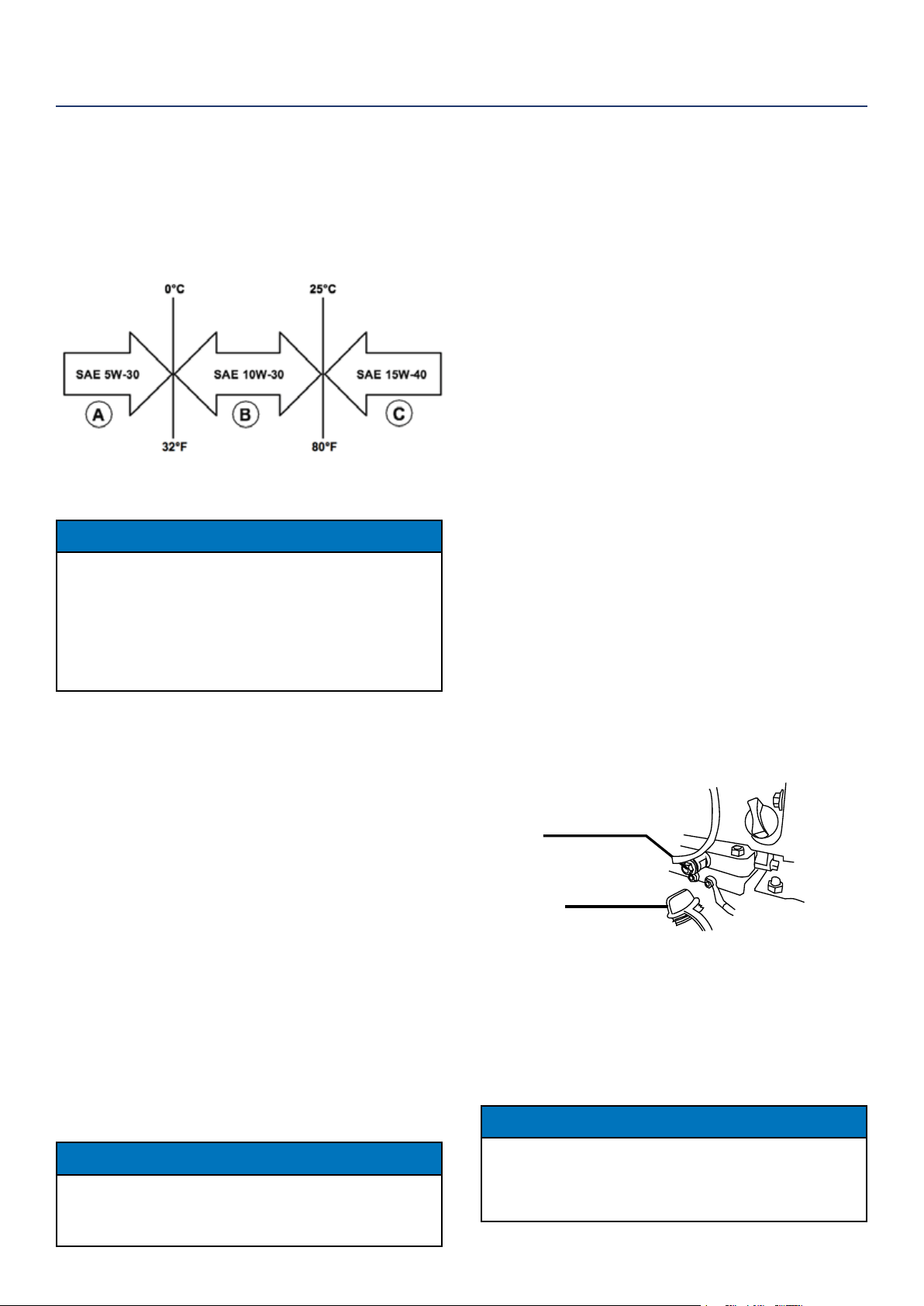
7. Select the proper engine oil as specied in Figure 10.
8. Using the supplied oil funnel, slowly add engine oil
to the engine. Stop frequently to check the oil level
and avoid overlling.
CHANGING ENGINE OIL
1. Stop the engine.
2. Let engine sit and cool for several minutes (allow
crankcase pressure to equalize).
3. Remove the oil service panel to gain access to the
oil ll/drain plug.
4. Place oil pan (or suitable container) under the
rubber plug just below the oil ll/drain cap.
5. Unscrew the rubber plug so the oil can drain out
the bottom of the generator.
6. Using a 10mm wrench, remove the oil drain bolt
(pictured below) to allow oil to drain.
Rubber oil plug
Oil drain bolt
7. Allow oil to completely drain, dispose of used
engine oil properly.
8. Fill crankcase with oil following the steps outlined in
Adding Engine Oil above and tighten oil plug.
9. Use a rag and remove access oil at the bottom of
the unit and replace the rubber oil cap as well as
the oil drain bolt. Replace access panel.
NOTICE
Never dispose of used engine oil by dumping the oil into a sewer,
on the ground, or into groundwater or waterways. Always be
environmentally responsible. Follow the guidelines of the EPA or
other governmental agencies for proper disposal of hazardous
materials. Consult local authorities or reclamation facility.
ENGINE OIL MAINTENANCE
Engine Oil Specication
1. Only use the engine oil specied in Figure 10.
2. Only use 4-stroke/cycle engine oil. NEVER USE
2-STROKE/CYCLE OIL. Synthetic oil is an
acceptable substitute for conventional oil.
Figure 10: Recommended oil
CHECKING ENGINE OIL
NOTICE
Always maintain proper engine oil level. Failure to
maintain proper engine oil level could result in severe
damage to the engine and/or shorten the life of the
engine.
Always use the specied engine oil. Failure to use the
specied engine oil can cause accelerated wear and/
or shorten the life of the engine.
Engine oil level should be checked before every use.
1. Always operate or maintain the inverter on a at
surface.
2. Stop engine if running.
3. Let engine sit and cool for several minutes (allow
crankcase pressure to equalize).
4. Remove the oil service panel to access the oil ll/
drain plug (see Figure 3 in Initial Oil Fill section).
5. With a damp rag, clean around the oil ll/drain plug.
6. Remove the oil ll/drain plug.
7. Check oil level: When checking the engine oil, remove
the oil ll/ drain plug (see Figure 4 Initial Oil Fill
section).
• The oil level is acceptable if oil is visible at the
bottom of the threads of the oil ll plug.
• If oil level is low, add to the correct level using
the supplied oil ll bottle. Do not overll the oil
crankcase.
NOTICE
Engine oil must always be checked and added when the inverter is
on a at, level surface, or an inaccurate reading may result, causing
serious engine damage.
MAINTENANCE
22 | Westinghouse Portable Power
4. Remove the foam element from the air cleaner
housing.
5. Wash the foam air lter element by submerging
the element in a solution of household detergent
soap and warm water. Slowly squeeze the foam to
thoroughly clean.
NOTICE
NEVER twist or tear the foam air lter element
during cleaning or drying. Only apply slow but rm
squeezing action.
6. Rinse in clean water by submerging the air lter el-
ement in fresh water and applying a slow squeezing
action (see Figure 13).
Figure 13: Squeeze air lter
NOTICE
Never dispose of soap cleaning solution used to
clean the air lter by dumping the solution into
a sewer, on the ground, or into ground water or
waterways. Always be environmentally responsible.
Follow the guidelines of the EPA or other
governmental agencies for proper disposal of
hazardous materials. Consult local authorities or
reclamation facility.
7. Dispose of used soap cleaning solution properly.
8. Dry the air lter element by again applying a slow
rm squeezing action.
9. Return the air lter element to its position in the air
cleaner housing.
10. Install the air cleaner cover, making sure the knobs
lock into place.
11. Install the engine service panel.
AIR FILTER MAINTENANCE
WARNING
Never use gasoline or other ammable
solvents to clean the air lter. Use only
household detergent soap to clean the
air lter.
Cleaning the Air Filter
The air lter must be cleaned after every 50 hours of
use or 3 months (frequency should be increased if
inverter is operated in a dusty environment).
1. Turn o the inverter and let it cool for several min-
utes if running.
2. Remove the Engine Service Panel to gain access to
the air lter (see Figure 11).
Figure 11: Remove engine service panel
3. Turn the 2 knobs on the air cleaner to unlock the
cover. Tip the cover down to access the foam
element (see Figure 12).
MAINTENANCE
Figure 12: Unlock air lter cover
Westinghouse Portable Power | 23
SPARK PLUG MAINTENANCE
The spark plug must be checked and cleaned after ev-
ery 100 hours of use or 6 months and must be replaced
after 300 hours of use or every year.
1. Stop the inverter and let it cool for several minutes
if running.
2. Move the inverter to a at, level surface.
3. Remove the Engine Service Panel to gain access to
the spark plug (see Figure in Air Filter Maintenance).
4. Remove the spark plug cover by rmly pulling the
metal spark plug boot handle directly away from
the engine (see Figure 16).
Figure 16: Pull o spark plug cover
NOTICE
Never apply any side load or move the spark plug
laterally when removing the spark plug. Applying a
side load or moving the spark plug laterally may crack
and damage the spark plug boot.
5. Clean area around the spark plug.
6. Using the spark plug socket wrench provided,
remove the spark plug from the cylinder head (see
Figure 17).
Figure 17: Remove spark plug
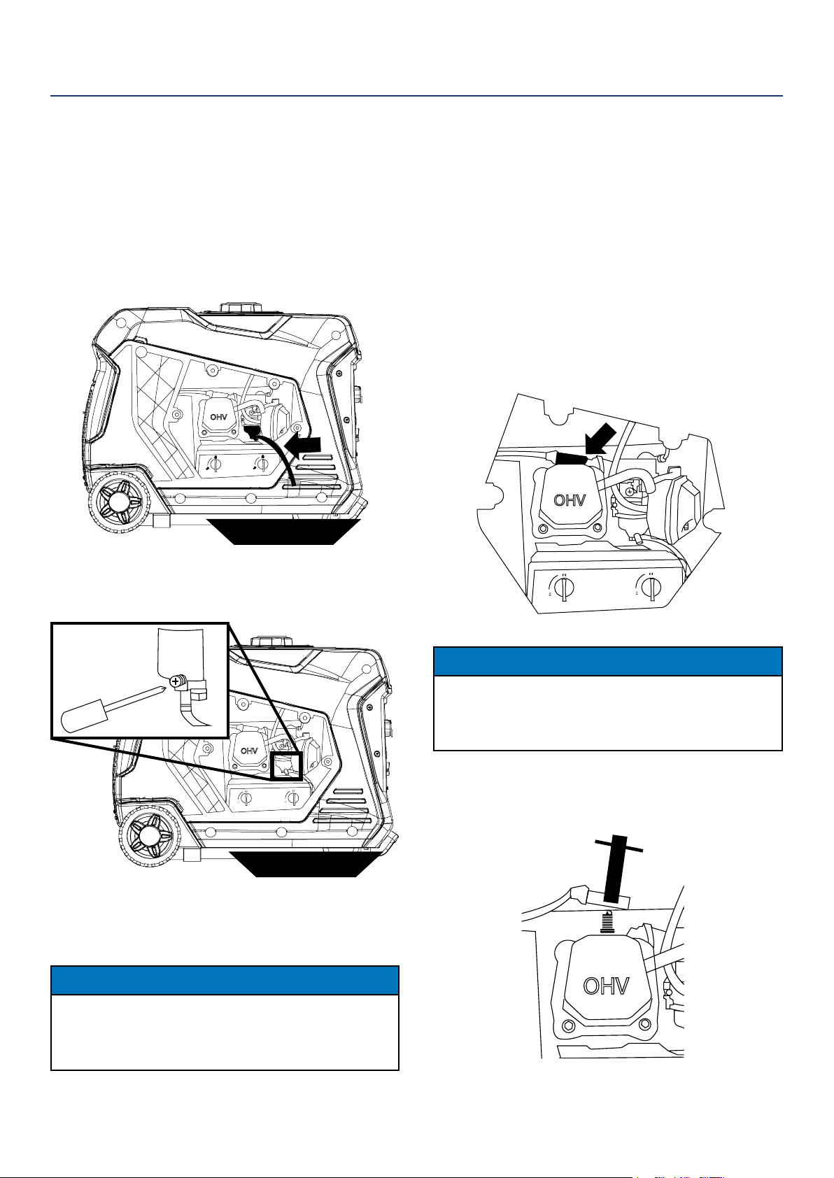
DRAINING THE FLOAT BOWL
1. Remove the Engine Service Panel to access the
carburetor (see Figure 11 in Air Filter Maintenance).
2. Locate the clear plastic hose from the oat that is
extending towards the bottom of the inverter, pull
those hose outside the body and place a suitable
container under it to catch the drained fuel (see
Figure 14).
Figure 14: Fuel drain hose
3. Loosen the oat bowl drain screw until fuel is seen
draining from the oat bowl (see Figure 15).
Figure 15: Loosen oat bowl screw
4. Allow fuel to drain into the container, and then
tighten the oat bowl drain screw.
NOTICE
Never dispose of fuel by dumping fuel into a sewer, on the ground,
or into groundwater or waterways. Always be environmentally
responsible. Follow the guidelines of the EPA or other
governmental agencies for proper disposal of hazardous materials.
Consult local authorities or reclamation facility.
5. Install the engine service panel.
MAINTENANCE
fuel pan
fuel pan
24 | Westinghouse Portable Power
Spark Plug Maintenance - Continued
7. Place a clean rag over the opening created by the
removal of the spark plug to make sure no dirt can
get into the combustion chamber.
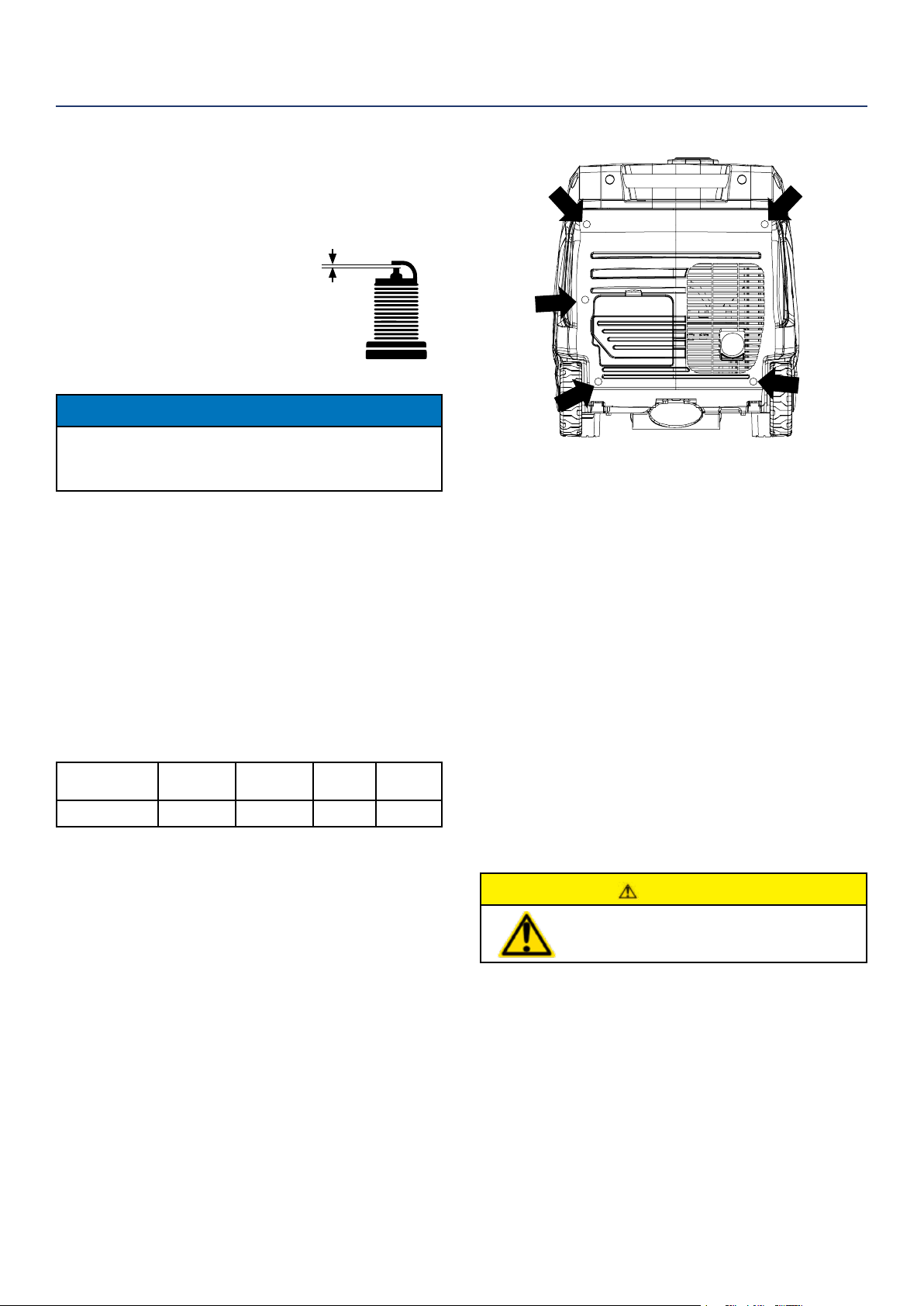
8. Inspect the spark plug for:
• Cracked or chipped insulator
• Excessive wear
• Spark plug gap of 0.032 in. (0.80 mm).
If the spark plug fails any one of the
conditions listed above, replace the plug.
NOTICE
Only use the recommended spark plug. See chart
below. Using a non- recommended spark plug could
result in damage to the engine.
9. Install the spark plug by carefully following the
steps outlined below:
a. Carefully insert the spark plug back into the
cylinder head. Hand-thread the spark plug until
it bottoms out.
b. Using the spark plug socket wrench provided,
turn the spark plug to ensure it is fully seated.
c. Replace the spark plug boot, making sure the
boot fully engages the spark plug’s tip.
d. Install the spark plug access cover.
Recommended Spark Plug Replacement:
Westinghouse
Model Number
Torch Spark
plug
Champion Bosch Autolite
iGen4500DF
F7RTC N9YC W7DC 52
CLEANING THE SPARK ARRESTOR
Check and clean the spark arrestor after every 100
hours of use or 6 months.
1. Stop the inverter and let it cool for several minutes
if running.
2. Move the inverter to a at, level surface.
3. Remove the screws holding the muer cover in
place (see Figure 18).
4. Loosen the clamp holding the spark arrestor onto
the muer.
5. Slide the spark arrestor band clamp o the spark
arrestor screen.
6. Pull the spark arrestor screen o the muer
exhaust pipe.
7. Using a wire brush, remove any dirt and debris that
may have collected on the spark arrestor screen.
8. If the spark arrestor screen shows signs of wear
(rips, tears or large openings in the screen), replace
the spark arrestor screen.
9. Install the spark arrestor components in the
following order:
a. Place spark arrestor screen over the muer
exhaust pipe. Push on the screen until it fully
bottoms out.
b. Place the spark arrestor band clamp over the
screen and tighten with a athead screwdriver
10. Replace the discharge gate.
CHECKING AND ADJUSTING VALVE LASH
CAUTION
Checking and adjusting valve lash
must be done when the engine is cold.
1. Remove the rocker arm cover and carefully remove
the gasket. If the gasket is torn or damaged, it must
be replaced.
2. Remove the spark plug so the engine can be
rotated more easily.
3. Rotate the engine to top dead center (TDC) of the
compression stroke. Looking through the spark
plug hole, the piston should be at the top.
SPARK PLUG GAP
MAINTENANCE
Figure 18: Remove muer access panel
Westinghouse Portable Power | 25
4. Both the rocker arms should be loose at TDC on
the compression stroke. If they are not, rotate the
engine 360°.
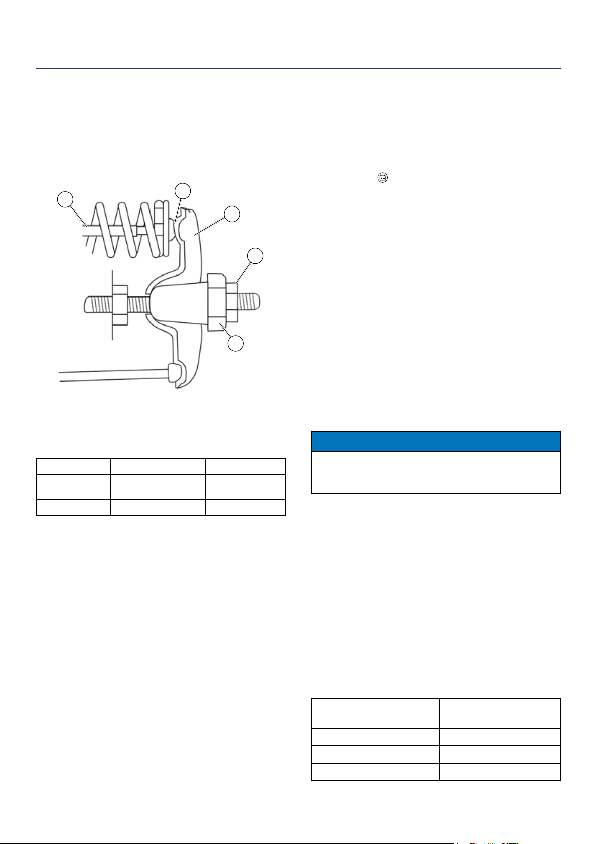
5. Insert a feeler gauge between the rocker arm and
the push rod and check for clearance (see Figure 19).
See table below for valve lash specications
Figure 19
(1) Push Rod, (2) Feeler Gauge Area
(3) Rocker Arm, (4) Jam Nut, (5) Adjusting Nut
Standard Valve Lash
Intake Valve Exhaust Valve
Valve Lash
0.0035 ± 0.0043 in
(0.09 ± 0.11 mm)
0.0043 ± 0.0051 in
(0.11 ± 0.13 mm)
Bolt Torque
8-12N.m 8-12N.m
6. If an adjustment is required, hold the adjusting nut
and loosen the jam nut.
7. Turn the adjusting nut to obtain the correct valve
lash. When the valve lash is correct, hold the ad-
justing nut and tighten the jam nut to 106 in-lb (12
N•m).
8. Recheck the valve lash after tightening the jam nut.
9. Perform this procedure for both the intake and
exhaust valves.
10. Install the rocker arm cover, gasket and spark plug.
CLEANING THE INVERTER
It is important to inspect and clean the inverter before
every use.
Clean All Engine Air Inlet and Outlet Ports – Make
sure all engine air inlet and outlet ports are clean of any
dirt and debris to ensure the engine does not run hot.
MAINTENANCE
1
2
3
4
5
BATTERY SERVICE
To ensure the battery remains charged, the generator
should be started every 2 to 3 months and run for a
minimum of 15 minutes or a charger should be plugged
into the generator and the generator should be charged
overnight. Plug the cord from the charger into the
charging port “
” on the generator. Plug the charger
into a 110/120-volt AC outlet.
Battery Replacement
1. Remove the engine service panel (see Figure 11 in
Air Filter Maintenance section)
2. Remove the spark plug wire from spark plug (see
Figure 16 in Spark Plug Maintenance section).
3. Remove battery service panel
(see Figure 1 Hooking Up the Battery section).
4. Loosen the rubber strap holding the battery in
place.
5. Disconnect the black negative (-) battery cable from
the battery rst.
6. Disconnect the red positive (+) battery cable
second and remove the battery.
NOTICE
Dispose of the used battery properly according to
the guidelines established by your local or state
government.
7. Install the new battery into the generator frame.
8. Connect the red positive (+) battery cable to the
battery rst.
9. Connect the black negative (-) battery cable to the
battery second.
10. Replace rubber strap to hold battery in place.
11. Replace battery service panel.
12. Install the spark plug wire onto spark plug.
13. Replace engine service panel.
See below for the battery specication
when replacing the battery.
After Market Battery
Model
YT5AL
Volts 12
Amp Hr 5
Dimensions 4.63 in by 2.38 in by 5 in
26 | Westinghouse Portable Power
4. Start the engine on gasoline and allow the inverter
to run until all the remaining gasoline in the fuel
lines and carburetor is consumed and the engine
shuts o.
5. Drain any remaining fuel from the oat bowl. See
Draining the Float Bowl section.
6. Change the oil (see Changing Engine Oil
section).
7. Remove the spark plug (see Spark Plug
Maintenance section) and place about 1 tablespoon
of oil in the spark plug opening. While placing a
clean rag over the spark plug opening, slowly pull
the recoil handle to allow the engine to turn over
several times. This will distribute the oil and protect
the cylinder wall from corroding during storage.
8. Replace the spark plug (see Spark Plug
Maintenance section).
9. Move the inverter to a clean, dry place for storage.
STORAGE
WARNING
Never store an inverter with fuel in the
tank indoors or in a poorly ventilated
area where the fumes can come in
contact with an ignition source such
as a: 1) pilot light of a stove, water
heater, clothes dryer or any other gas
appliance; or 2) spark from an electric
appliance.
NOTICE
Gasoline stored for as little as 60 days can go bad,
causing gum, varnish and corrosive buildup in fuel
lines, fuel passages and the engine. This corrosive
buildup restricts the ow of fuel, preventing an engine
from starting after a prolonged storage period.
Proper care should be taken to prepare the inverter for
any storage
1. Make sure battery switch is OFF.
2. Clean the inverter.
3. Siphon all gasoline from the fuel tank as best as
possible.
MAINTENANCE
WARNING
Before attempting to service or troubleshoot the generator, the owner or service technician must rst read the owner’s
manual and understand and follow all safety instructions. Failure to follow all instructions may result in conditions that
can lead to voiding of the EPA certication or product warranty, serious personal injury, property damage or even death.
TROUBLESHOOTING
PROBLEM POTENTIAL CAUSE SOLUTION
Engine is running, but no
electrical output
1. Circuit breakers are tripped. 1. Reset the circuit breakers and check for
overload condition.
2. The power cord’s plug connector is not fully
engaged in the generator’s outlet.
2. Verify plug connector is rmly engaged in
the generator’s outlet.
3. Faulty or defective power cord. 3. Replace power cord.
4. Faulty or defective electrical appliance. 4. Try connecting a known good appliance
to verify the generator is producing electrical
power.
5. If trying 1-4 above does not solve the
problem, the cause might be the generator has
a fault.
6. Take the generator to your nearest
authorized service dealer.
Engine runs
erratic; does not hold a
steady RPM.
1. Dirty air lter. 1. Clean the air lter.
2. Applied loads maybe cycling on and o. 2. As applied loads cycle, changes in engine
speed may occur; this is a normal condition.
3. If trying 1-2 above does not solve
the problem, the cause might be a
fault in the inverter.
3. Take the generator to your nearest
authorized service dealer.

Westinghouse Portable Power | 27
TROUBLESHOOTING
Inverter suddenly
stops running.
1. Inverter is out of fuel. 1. Check fuel level. Add fuel if necessary.
2. The low oil shut down switch has stopped the
engine.
2. Check oil level and add oil if necessary.
3. Too much load 3. Restart the inverter and reduce the load.
Frost on the propane tank
or regulator
1. This can be a normal occurrence caused when
liquid propane changes phase to a gas. As this
process occurs the fuel tank or regulator will cool
and allow humid air surrounding the propane tank or
regulator to condense into frost.
1. As this can be normal, providing all the
propane fuel handling equipment is functioning
normally, no remedy is needed.
2. The propane tank is not equipped with a OPD
(rollover protection device) and has been stored in a
horizontal position allowing liquid propane to enter
the downstream fuel handling equipment.
2. If you suspect your propane fuel tank is
not equipped with a OPD device, discontinue
operation immediately and replace the propane
fuel tank with a propane tank equipped with a
roll over protection device.
3. Propane fuel tank over lled. 3. If you suspect your propane fuel tank
has been overlled, discontinue operation
immediately and return the propane fuel tank to
the place of purchase or relling.
Propane fuel smell
1. Fuel regulator or fuel hose and ttings not
securely sealed.
1. Using a soap solution check each connection
and tighten as needed.
2. Propane fuel regulator vent active. 2. The propane fuel regulator is equipped with
a small vent that will allow a small amount of
propane fuel vapor to escape from the regulator
when the propane tank valve is opened. This
can be normal providing the venting of the
propane is brief. If you suspect that this is
abnormal, immediately discontinue use and have
the propane regulator inspected by a qualied
technician.
3. Residual fuel from the carburetor dispersing after
operation.
3. Normal, no remedy is needed.
Poor performance
or engine stalling on
propane
1. Propane fuel line kinked or crushed. 1. Inspect propane fuel line and remove kinks or
other obstructions.
2. Fuel selector valve not properly positioned. 2. Rotate the fuel valve fully until the pointer is
directly in line with the desired fuel.
3. Gasoline not purged from the carburetor before
switching to propane.
3. Turn the propane fuel tank valve to closed.
Move the fuel selector valve to propane. Turn the
gasoline fuel valve to o. Start the engine and
allow the engine to run until the fuel has been
consumed in the carburetor. Begin propane start
up procedure.
28 | Westinghouse Portable Power
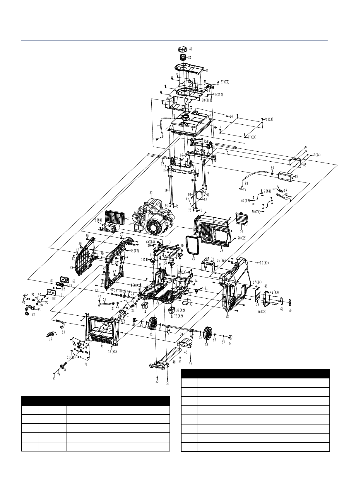
iGen4500DF EXPLODED VIEW
NO. PAR T. DESCRIPTION
6 - NUT M8
7 - BOLT M6X12
8 100562 LEFT SKELETON
9 - BACK POST
10 - FRONT POST
11 - BRACKET
12 100567 HANDLE
13 150526 FUEL TANK
NO. PAR T. DESCRIPTION
1 - BOTTOM MOTOR BRACKET LEFT
2 - BOTTOM MOTOR BRACKET RIGHT
3 - BOTTOM MOTOR BRACKET BACK
4 - SQUARE NUTS
5 100578 DAMPER
NOTE: Parts with no number are not stocked by
the manufcturer. Please call our service team if
you have questions.

Westinghouse Portable Power | 29
iGen4500DF EXPLODED VIEW PART NUMBERS
NO. PAR T. DESCRIPTION
14 - VIBRATION ISOLATION PAD
15 - FRONT TOP BRACKET
16 - BACK TOP BRACKET
17 120538 INVERTER MODULE
18 - INVERTER BRACKET
19 - DEPUTY WIRING HARNESS
20 - BOLT M8X20
21 100569 INTAKE CRATE
22 - FUEL SELECT BRACKET
23 150535 FUEL VALVE
24 - FUEL LINE Φ4XΦ10XΦ6XΦ12-95L
25 - FUEL LINE Φ4XΦ10XΦ6XΦ12-55L
26 - FUEL LINE Φ4XΦ10-194L
27 - PIN
28 300248 RIGHT PANEL
29 100568 INSPECTION COVER
30 100574 AXLE
31 100579 BATTERY
32 100580 TIE WRAP
33 130526 DC VOLTAGE REGULATOR
34 300249 KNOB
35 150533 PLUG
36 - LOCKINMG M6
37 - CAP, CENTRIFUGAL COVER
38 100570 RUBBER FOOT
39 100564 DISCHARGE GRATE
40 150530 FUEL TANK CAP
41 150528 SPLASH GUARD
42 - CORE PULLING RIVETS
43 100571 WHEEL
44 100577 HUB CAP
45 100565 MUFFLER SEAL
46 100573 HANDLE BRACKET
47 - CLIP, FUEL LINE
48 100572 HANDLE ASSEMBLY
49 - HANDLE DECORATED
50 170515 RECOIL ANCHOR
51 150532 BOLT M5X12
52 100561 TOP COVER
53 300250 LEFT SIDE PANEL
54 100566 DISCHARGE COVER
55 - BOLT M6X40
56 150527 CONNECTING PIPE
57 - ENGINE BOTTOM BOARD
58 150529 STRAINER
NO. PAR T. DESCRIPTION
59 150534 FUEL FILTER
60 150536 CLIP, FUEL LINE
61 170514 GRIP STARTER
62 - GROUNDING WIRE
63 - WHEEL A WILD CARD
64 - BOLT M8X30
65 100575 WHEEL WASHER
66 - FLAT WASHER
67 - HEX FLANGE SCREWS M6X20
68 300251 FUEL SELECT GEAR LEFT
69 300252 FUEL SELECT BACK PLATE
70 - TOOTH TYPE GASKET
71 300253 PANEL COMPLETE
72 - CLIP, FUEL LINE
73 - BOLT M6X25
74 - STOP
75 - BOLT M6X20
76 - BOLT M6X20
77 - GASKET, ROTOR BOLT
78 - CROSS RECESSED PAN HEAD BOLTS M6X16
79 - VIBRATION ISOLATION PAD
80 - BOLT M6X16
81 300254 BASE OIL COVER
82 300255 ENGINE COMPLETE
83 - CORRUGATED PIPE
84 - PUII THE TRAY
85 150538 CANESTER BRACKET
86 130525 CONRTOLLER
87 150520 CARBON TANK
88 150540 CONNECTING PIPE
89 150539 VENT HOSE
90 - NUTM6
91 - BOLT M6X30
92 300256 GAS INLET PLUG
93 300257 SHEATH
94 300258 GAS INTAKE CONNECTOR
95 300259 L CONNECT
96 300260 GAS LINE CONNECT
97 300261 LOW PRESSURE PIPE
98 300262 SEALING WASHER
99 300263 SWITCH SHAFT
100 300264 DISC BOLT M5*10
101 300265 FRONT FUEL SELECT COVER
102 300266 CROSS SCREW M4*12.
103 300267 FUEL SELECT GEAR RIGHT
30 | Westinghouse Portable Power
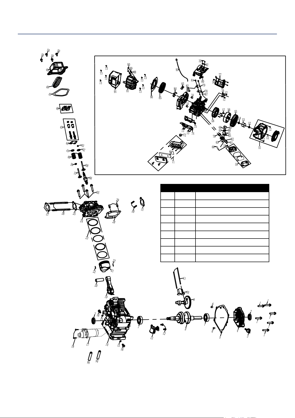
iGen4500DF ENGINE VIEW
NO. PA RT. DESCRIPTION
1 - BOLT M8X30
2 - OIL SEAL
3 180581 DIPSTICK
4 - COVER ASSEMBLY, CRANKCASE
5 - PACKING, CASECOVER
6 - DOWEL PIN,CASECOVER
7 - BALL BEARING
8 - CRANKSHAFT ASSEMBLY
9 - CAMSHAFT ASSEMBLY
NOTE: Parts with no number are not stocked by
the manufcturer. Please call our service team if
you have questions.

Westinghouse Portable Power | 31
iGen4500DF ENGINE VIEW PART NUMBERS
NO. PA RT. DESCRIPTION
10 - LIFTER, VALVE
11 - ROD, PUSH
12 - BOLT M6X16
13 180582 STARTER SOLENOID
14 - CRANKCASE
15 - WASHER, DRAIN PLUG
16 - BOLT DRAIN PLUG
17 170516 STARTING MOTOR ASSEMBLY
18 - BOLT M6X25
19 180850 ROD ASSEMBLY., CONNECTING
20 180851 PIN, PISTON
21 180852 PISTON
22 180853 CLIP, PISTON
23 180854 SCRAPER RING SET, PISTON
24 180855 CYLINDER HEAD
25 180856 PACKING, INTAKE
26 180857 BOLT, STUD
27 180858 PACKING, CARBURETOR
28 180859 GASKET, CYLINDER HEAD
29 180860 PIN DOWEL
30 180861 BOLT, STUD
31 180862 PACKING, EXHAUST
32 - BOLT M8X12
33 - CAP, CENTRIFUGAL COVER
34 - DOWEL PIN, CASECOVER
35 - BOLT M8X60
36 180580 SPARK PLUG
37 180863 VALVE, IN
38 180864 VALVE EXHAUST
39 180865 RETURNER, INTAKE VALVE
40 180866 SPRING, VALVE
41 180867 SEAT, VALVE SPRING, IN
42 180868 SEAT, VALVE SPRING, EX
43 180869 ROTATOR
44 180870 PLATE, PUSH ROD GUIDE
45 180871 ADJUSTER ROCKER ARM
46 180872 ARM, ROCKER
47 180873 PACKING, HEADCOVER
48 - COVER COMP, CYLINDER HEAD
49 - COVER COMP, CYLINDER HEAD
50 - BOLT M6X12
51 170512 RECOIL STARTER W/FAN HOUSING
ASSY
52 - BOLT
53 - CUP, FLYWHEEL
NO. PA RT. DESCRIPTION
54 - NUT M14
55 - FAN, FLYWHEEL
56 - ROTOR
57 - BOLT M6X60
58 - STATOR
59 160505 CARBURETOR ASSEMBLY
60 - TUBE,BREATHER
61 100548 NUT M6
62 140517 SPACER, CARBURETOR
63 300268 CARBURETOR ASSEMBLY
64 140531 STEPPER MOTOR BRACKET
65 140533 CROSSING SCREW M4X25
66 140529 STEPPER MOTOR
67 140530 STEPPER MOTOR
68 140534 CROSSING SCREW M4X6
69 - WATERPROOF COVER
70 140535 INSULATOR, CARBURETOR
71 160504 AIR CLEANER ASSEMBLY
72 - TUBE, FUEL TANK TO CARBON
73 - BOLT M6X20
74 - BRACKET, AIR CLEANER
75 - SHROUD, UPPER
76 - THE TRIGGER
77 - SHROUD,RIGHT
78 - LGNITION COIL SUPPORT PLATE
79 180579 IGNITION COIL
80 - SHROUD, ABOVE
81 - BOLT M6X30
82 - CENTRIFUGAL FAN HOUSING.
83 - CAP,CENTRIFUGAL COVER
84 - BOLT M8X20
85 - FAN
86 - ISOLATOR
87 110510 MUFFLER COMP ASSY
88 110512 FLAT WASHER
89 110502 SPRING WASHER
90 180524 NUT M8
91 110511 SHIELD, MUFFLER
92 - CLAMP, CABLE CLAMP
93 110513 TEMPERATURE SENSOR
94 - CLIP, WIRE HARNESS
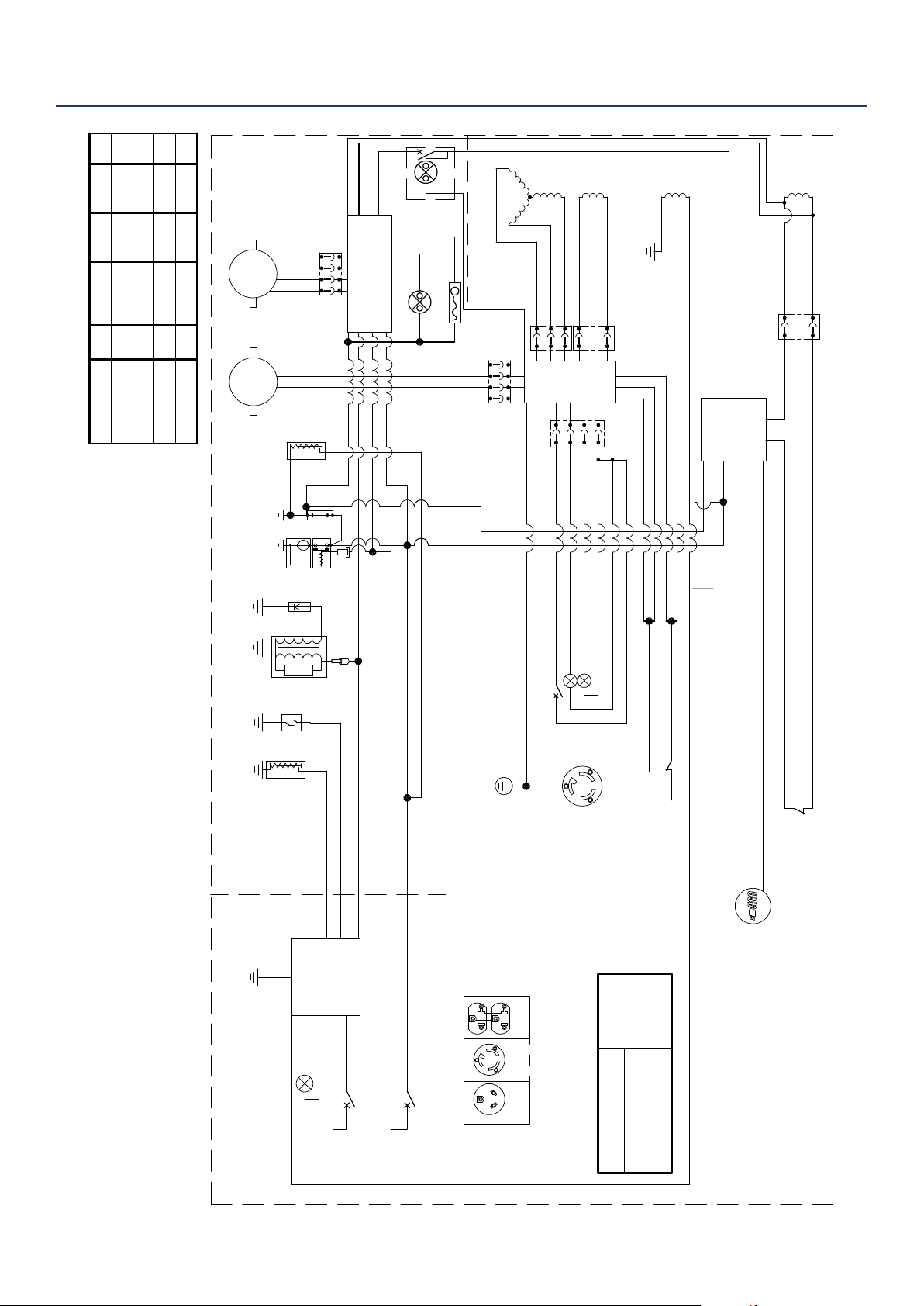
32 | Westinghouse Portable Power
iGen4500DF SCHEMATIC
DC
Winding
Generator
Control
power
winding
Main
winding
I nver t er
Bu 16AWG
Bu 16AWG
W20AWG
W20AWG
W16AWG
R 16AW
G
Bu 16AWG
Engine
8A Breaker
Regulated
Rectif ier
Bu 16AWG
Bu 16AWG
Bu 16AWG
R / W20AWG
B/W20AWG
R 18AWG
Bl 18AWG
5V USB
Control Panel
Bl 22AWG
R 22AWG
Y 22AWG
Bu 22AWG
Fu le Stepping Motor
SM
Br 20AWG
O 20AWG
Oil Indicator
W22AWG
Br 22AWG
Bu 22AWG
Gr 22AWG
W22AWG
W22AWG
Fault indicator
R
u
n
ning
lights
Idle sw it ch
Gas/LPG S
wit
ch
Bl
Br
R
Br/R
Bl ue
W
Gr
P
Y
Y/G
Bl / W Black/white
B/W
Y
Yellow
O
Pu
Purple
Bl ack
Red
Bu
White
Yellow
Pink
Orange
Yellow green
Brown/ red
Brown
Gray
Black/whit e
Breaker
Y/G 12AWG
Y/G 12AWG
R 14AWG
R 14AWG
W14AWG
W14AWG
R 12AWG
5V
T.C. I
l gnition
Spark
plug
Motor
Battery
M
W20AWG
R 20AWG
Supply
winding
T. C. I unit
W12AWG
R 12AWG
Oil
Sensor
R 20AWG
T.C. I
winding
R
Bl
Bu 20AWG
B/ W20AWG
Bl 20AWG
Bl 20AWG
R 20AWG
R 20AWG
W20AWG
R 20AWGR 20AWG
Bl 20AWG
Bl 20AWG
L5- 30R TT- 30R
5- 20R( A)
Flameout Switch
Bl 22AWG
R 22AWG
Y 22AWG
Bu 22AWG
Choke Stepping Motor
SM
Remote-Start Modular
20 AWG Bl/ W
20 AWG Bu
Start light
Temperature Sensor
Solenoid
valve
O 20AWG
O 20AWG
R 20AWG
W20AWG
Bu 20AWG
Bl 20AWG
W12AWG
Model
Al ternative Chois e
5-20R(A) +20A Breaker
+L5- 30R+TT- 30R
5- 20R(A)
V 2
+20A Breaker
V 2
+L5- 30R/TT-30R
Battery SW.
light
20 AWG Bu
iGen4500DF
iGen4500DF

Westinghouse Portable Power | 33
Version 04.28.18KD
