USER MANUAL
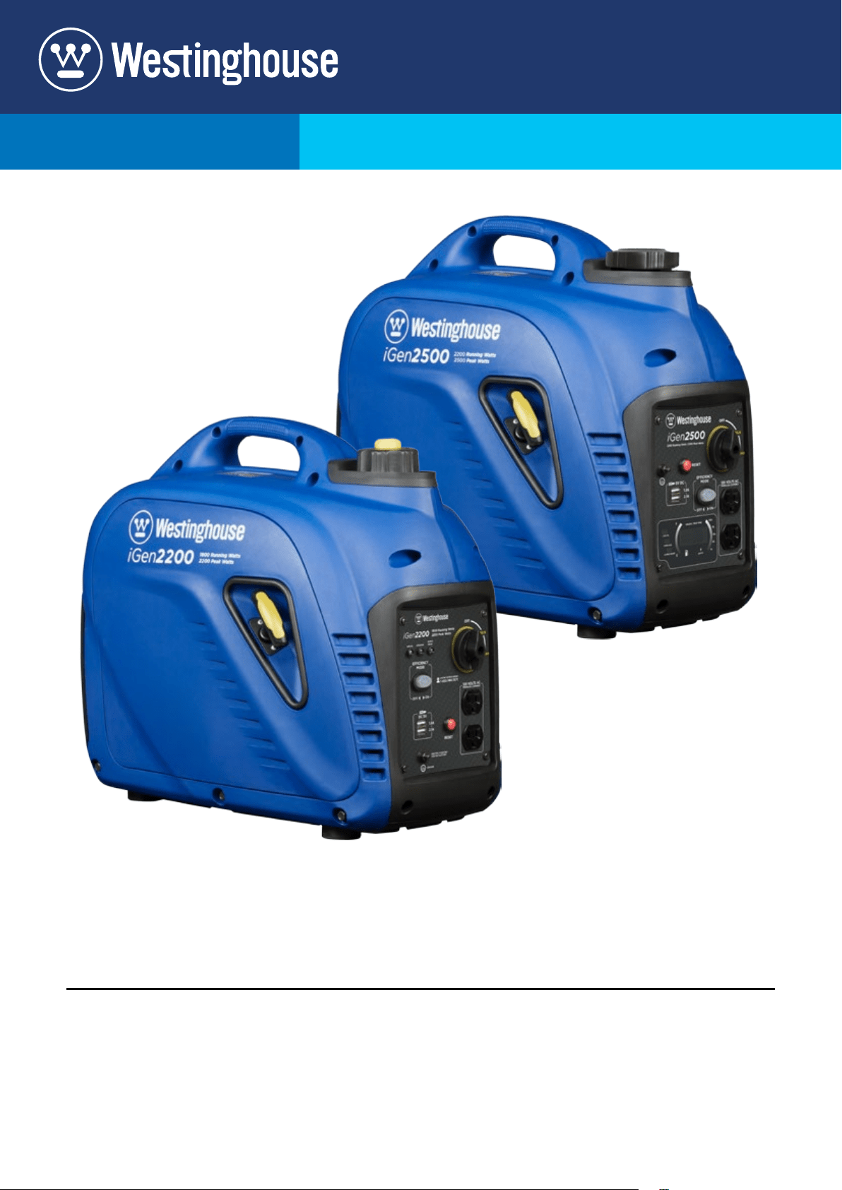
iGen2200
Digital Inverter Generator
1800 Running Watts | 2200 Peak Watts
iGen2500
Digital Inverter Generator
2200 Running Watts | 2500 Peak Watts
FOR MODELS:
2 | Westinghouse Portable Power
DISCLAIMERS:
All information, illustrations and specications in this manual are based on the latest information available at
the time of publishing. The illustrations used in this manual are intended as representative reference views only.
Moreover, because of our continuous product improvement policy, we may modify information, illustrations and/or
specications to explain and/or exemplify a product, service or maintenance improvement. We reserve the right
to make any change at any time without notice. Some images may vary depending upon which model is shown.
ALL RIGHTS RESERVED:
No part of this publication may be reproduced or used in any form by any means – graphic, electronic or
mechanical, including photocopying, recording, taping or information storage and retrieval systems – without the
written permission of MWE Investments LLC.
DANGER
This manual contains important instructions for operating this inverter generator. For your safety
and the safety of others, be sure to read this manual thoroughly before operating the
generator. Failure to properly follow all instructions and precautions can cause you and
others to be seriously hurt or killed.
California
Proposition 65 Warning
The engine exhaust from this product
contains chemicals known to the state
of California to cause cancer, birth
defects or other reproductive harm.
California
Proposition 65 Warning
Certain components in this product and its
related accessories contain chemicals
known to the state of California to cause
cancer, birth defects or other reproductive
harm. Wash hands after handling.
Model
Number
Running
Watts
Peak
Watts
Fuel
Tank
Size
(L/G)
Rated
Speed
(RPM)
Ignition
Type
Spark
plug
Engine
Disp (cc)
Stroke X
Bore
Oil
Capacity
(L) Oil Type THD
iGen2200 1800 2200 4.5/1.2 5300 CDI E6RTC 80 49X43 0.35 10W30 <5%
iGen2500 2200 2500 3.8/1.0 5500 CDI E6RTC 98 52X46 0.35 10W30 <5%
iGen TECHNICAL SPECIFICATIONS
HAVE QUESTIONS?
Email us at service@wpowereq.com
or call 1-855-944-3571
Westinghouse Portable Power | 3
FOR YOUR RECORDS:
Date of Purchase:
Inverter Model Number:
Purchased from Store/Dealer:
Inverter Serial Number:
IMPORTANT: KEEP YOUR PURCHASE RECEIPT TO ENSURE TROUBLE-FREE WARRANTY
COVERAGE.
PRODUCT REGISTRATION
To ensure trouble-free warranty coverage, it is important you register your Westinghouse inverter.
You can register your generator by either:
1. Filling in the product registration form below and mailing to:
Product Registration
MWE Investments LLC
777 Manor Park Drive
Columbus, Ohio 43228
2. Registering your product Online at www.westinghouseportablepower.com/register-your-product/
To register your generator you will need to locate the following information:
WESTINGHOUSE PRODUCT REGISTRATION FORM
PERSONAL INFORMATION INVERTER INFORMATION
First Name: _______________________________________ Model Number: _____________________________________
Last Name: _______________________________________ Serial Number: ______________________________________
Street Address: ___________________________________ Date Purchased: ____________________________________
Street Address: ___________________________________ Purchased From: ____________________________________
City, State, ZIP: ____________________________________
Country: __________________________________________
Phone Number: ___________________________________
E-Mail: ___________________________________________
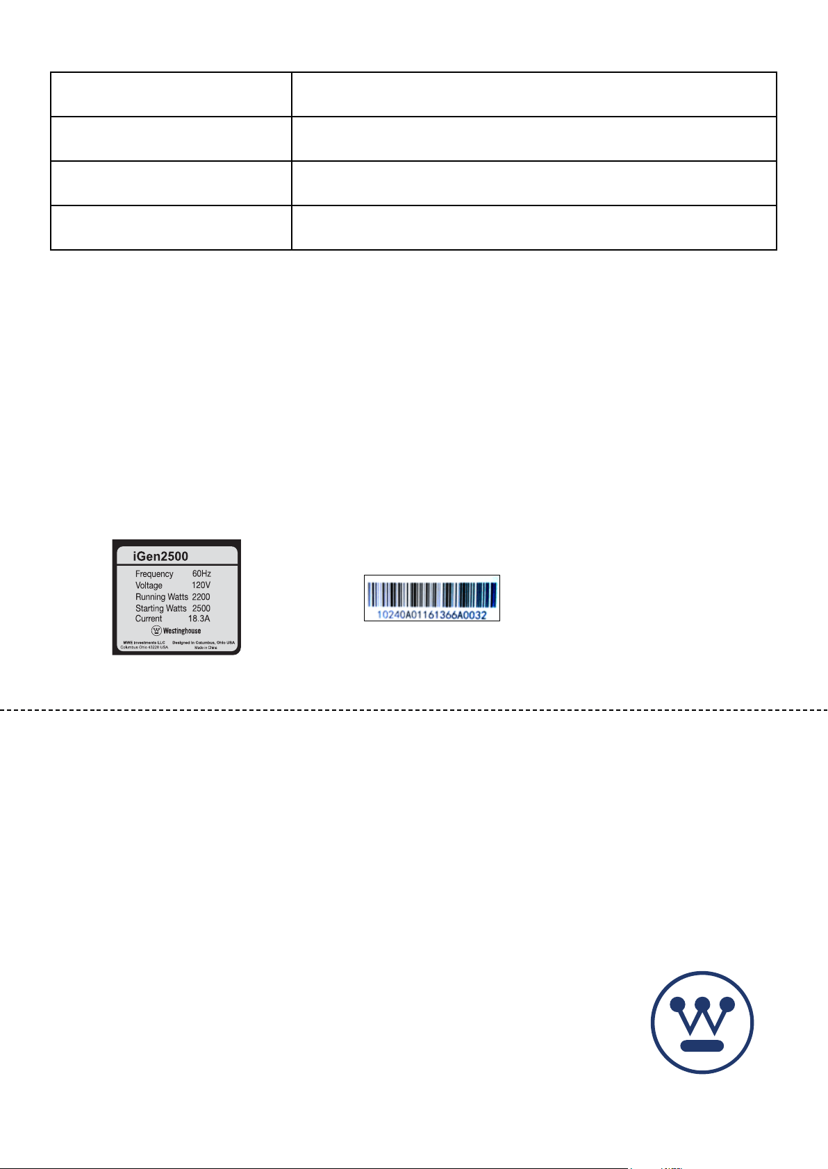
Model Info Decal located on side panel.
(See pages 7-8 for placement)
Serial Number which is located on
bottom of muer cover.

4 | Westinghouse Portable Power
TABLE OF CONTENTS
IGEN TECHNICAL SPECIFICATIONS .............2
PRODUCT REGISTRATION .....................3
For Your Records: ..........................3
Product Registration .......................3
Product Registration Form ...................3
SAFETY .....................................5
Safety Denitions ...........................5
Safety Symbol Denitions ....................5
General Safety Rules ........................6
Safety Labels and Decals ....................7
UNPACKING .................................7
FEATURES ..................................8
Basic Inverter Features iGen2200/2500 .........8
Control Panel Features iGen2200/2500 ..........9
LED Digital Data Display iGen2500 .............10
OPERATION .................................11
Before Starting the Inverter ...................11
Location Selection .......................11
Weather ................................11
Dry Surface .............................11
No Connected Loads .....................11
Grounding the iGen Inverters ...............11
Powercord ................................12
Inverter Paralleling Operation .................12
Initial Oil Fill ...............................13
Adding/Checking Engine Fluids and Fuel ........14
Checking and/or Adding Engine Oil. . . . . . . . . . . . . 14
Adding Gasoline to the Fuel Tank ..............14
Starting iGen2200/2500 .....................15
Stopping the Inverter ........................16
Using Eciency Mode .......................16
Resetting the Reset Breaker ..................16
MAINTENANCE ..............................17
Maintenance Schedule ......................17
Engine Oil Maintenance ......................18
Checking Engine Oil. . . . . . . . . . . . . . . . . . . . . . . . . 18
Adding Engine Oil ..........................18
Changing Engine Oil ........................19
Air Filter Maintenance .......................19
Cleaning the Air Filter ........................19
Draining the Float Bowl ......................20
Spark Plug Maintenance .....................21
Cleaning the Spark Arrestor ...................22
Checking and Adjusting Valve Lash. . . . . . . . . . . . . 22
Cleaning the Inverter ........................23
Storage ..................................23
TROUBLESHOOTING .........................24
EXPLODED AND ENGINE VIEWS ................25
iGen2200 Exploded View .....................25
iGen2200 Engine View .......................26
iGen2500 Exploded View .....................27
iGen2500 Engine View .......................28
iGen2200 Schematic ........................29
iGen2500 Schematic ........................30
Westinghouse Portable Power | 5
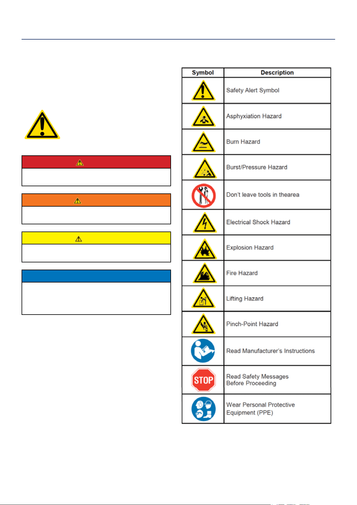
SAFETY DEFINITIONS
The words DANGER, WARNING, CAUTION and
NOTICE are used throughout this manual to highlight
important information. Be certain that the meanings of
these alerts are known to all who work on or near the
equipment.
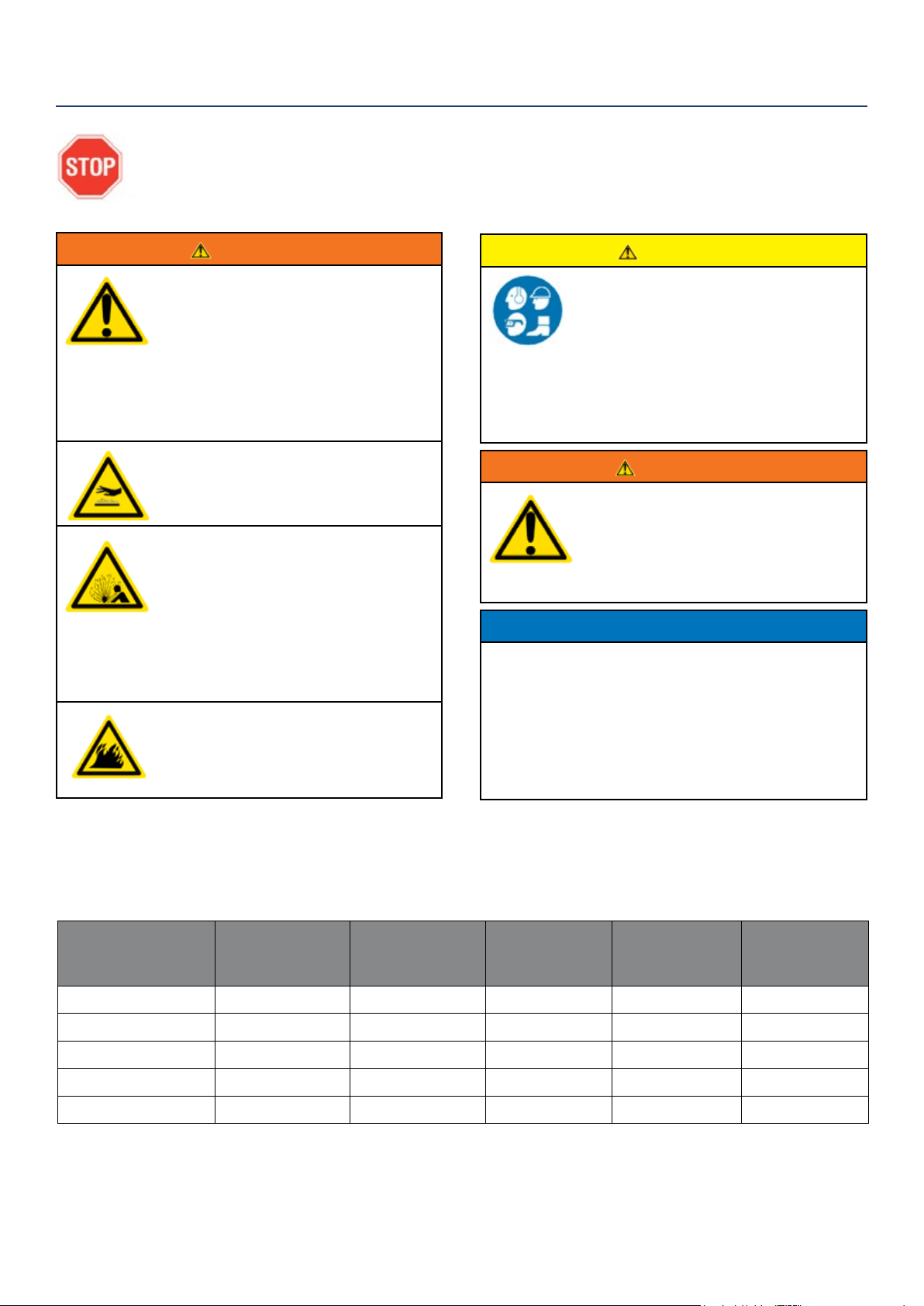
This safety alert symbol appears
with most safety statements. It
means attention, become alert, your
safety is involved! Please read and
abide by the message that follows
the safety alerts symbol.
DANGER
Indicates a hazardous situation which, if not
avoided, will result in death or serious injury.
WARNING
Indicates a hazardous situation which, if not
avoided, could result in death or serious injury.
CAUTION
Indicates a hazardous situation which, if not
avoided, could result in minor or moderate injury.
NOTICE
Indicates a situation which can cause damage
to the generator, personal property and/or the
environment, or cause the equipment to operate
improperly.
NOTE: Indicates a procedure, practice or condition
that should be followed in order for the
generator to function in the manner
intended.
SAFETY
SAFETY SYMBOL DEFINITIONS
6 | Westinghouse Portable Power
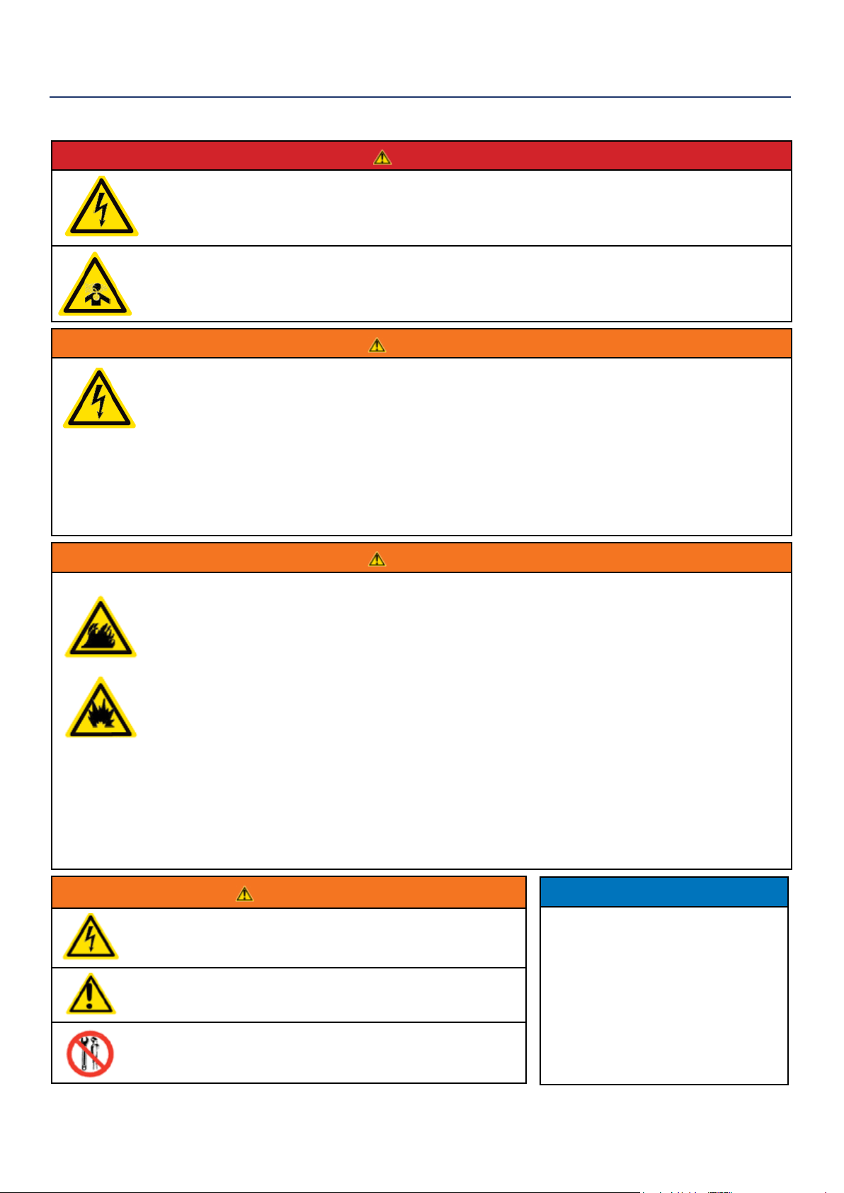
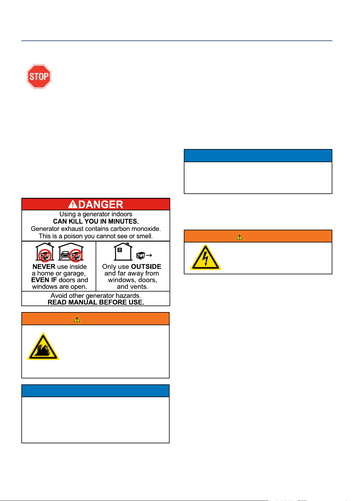
DANGER
Never use the inverter in a location that is wet or damp. Never expose the inverter to rain, snow,
water spray or standing water while in use. Protect the inverter from all hazardous weather
conditions. Moisture or ice can cause a short circuit or other malfunction in the electrical circuit.
Never operate the inverter in an enclosed area. Engine exhaust contains carbon monoxide. Only
operate the inverter outside and away from windows, doors and vents.
WARNING
Voltage produced by the inverter could result in death or serious injury.
• Never operate the inverter in rain or a ood plain unless proper precautions are taken to avoid
being subject to rain or a ood.
• Never use worn or damaged extension cords.
• Always have a licensed electrician connect the inverter to the utility circuit.
• Never touch an operating inverter if the inverter is wet or if you have wet hands.
• Never operate the inverter in highly conductive areas such as around metal decking or steel works.
• Always use grounded extension cords. Always use three-wire or double-insulated power tools.
• Never touch live terminals or bare wires while the inverter is operating.
• Be sure the inverter is properly grounded before operating.
WARNING
Gasoline and gasoline vapors are extremely ammable and explosive under certain conditions.
• Always refuel the generator outdoors, in a well-ventilated area.
• Never remove the fuel cap with the engine running.
• Never refuel the inverter while the engine is running. Always turn engine o and allow the
generator to cool before refueling.
• Only ll fuel tank with gasoline.
• Keep sparks, open ames or other form of ignition (such as match, cigarette, static electric
source) away when refueling.
• Never overll the fuel tank. Leave room for fuel to expand. Overlling the fuel tank can result in a
sudden overow of gasoline and result in spilled gasoline coming in contact with HOT surfaces.
Spilled fuel can ignite. If fuel is spilled on the inverter, wipe up any spills immediately. Dispose of
rag properly. Allow area of spilled fuel to dry before operating the inverter.
• Wear eye protection while refueling.
• Never use gasoline as a cleaning agent.
• Store any containers containing gasoline in a well-ventilated area, away from any combustibles or
source of ignition.
• Check for fuel leaks after refueling. Never operate the engine if a fuel leak is discovered.
WARNING
Never operate the inverter if powered items overheat,
electrical output drops, there is sparking, ames or smoke
coming from the inverter, or if the receptacles are damaged.
Never use the inverter to power medical support equipment.
Always remove any tools or other service equipment used
during maintenance from the inverter before operating.
NOTICE
Never modify the inverter.
Never operate the inverter if it
vibrates at high levels, if engine
speed changes greatly or if the
engine misres often.
Always disconnect tools or
appliances from the
inverter before starting.
GENERAL SAFETY RULES
SAFETY
Westinghouse Portable Power | 7
5
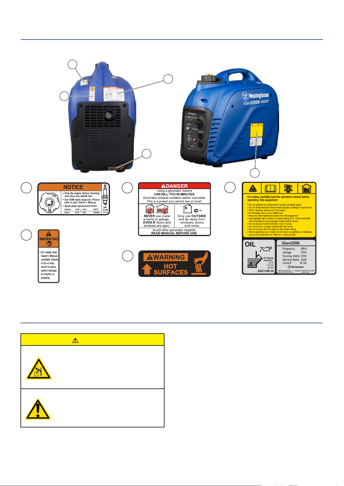
SAFETY
SAFETY LABELS AND DECALS IGEN2200 AND IGEN2500
1 2
3
5
4
CAUTION
Always have assistance when lifting
the inverter. The inverter is heavy;
lifting it could cause bodily harm.
Avoid cutting on or near staples
to prevent personal injury.
UNPACKING
2
3
4
1
Tools required – box cutter or similar device.
1. Carefully cut the packing tape on top of the carton.
2. Remove socket wrench, oil and funnel and
save for later.
3. Carefully cut two sides of the carton to
remove the inverter.
WHAT COMES IN THE BOX
Spark Plug Socket Wrench (1)
Owner Manual (1)
Quick Start Guide (1)
Warranty Information (1)
Funnel (1)
.37 QT/.35 L Bottle of 10W-30 Oil (1)
8 | Westinghouse Portable Power
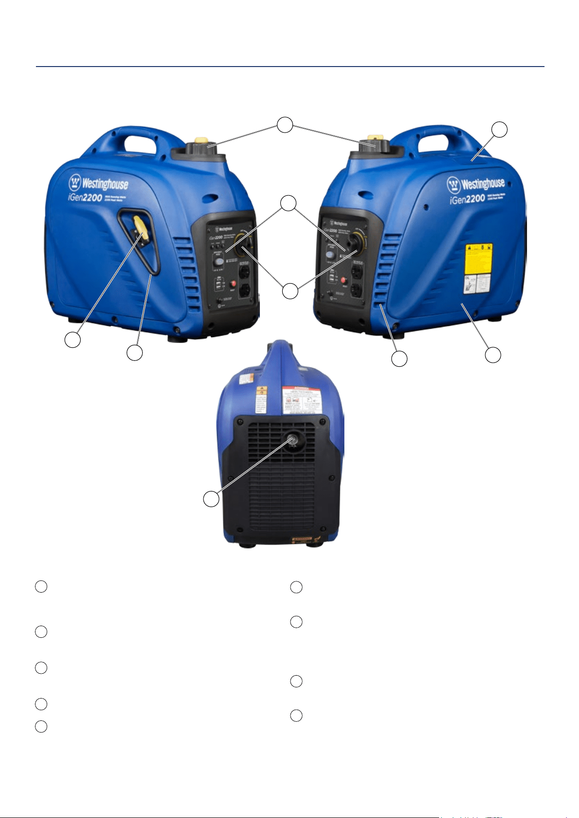
FEATURES
BASIC INVERTER FEATURES IGEN2200 & IGEN2500
Fuel Cap and Vent (vent: iGen2200 only): Open
the vent to run the engine and close the vent
when the engine is o.
Control Panel: Contains the reset breaker,
outlets and warning lights.
Spark Plug Access Cover: Remove the cover
to service the spark plug.
Recoil Handle: Pull to start the engine.
Engine Control Switch: Sets the choke, turns
the fuel on and o.
1
5
6
7
8
9
2
3
4
2
1
3
4
5
6
7
8
9
Engine Service Panel: Remove the panel to access
the engine for maintenance.
Muer and Spark Arrestor: Avoid contact until the
engine is cooled down. The spark arrestor prevents
sparks from exiting the muer. It must be removed for
servicing.
Engine Cooling Vents: Helps move airow in unit to
regulate engine temperatures.
Recoil Handle Protective Cover: Prevents pull cord
wire from damaging inverter body.
Westinghouse Portable Power | 9
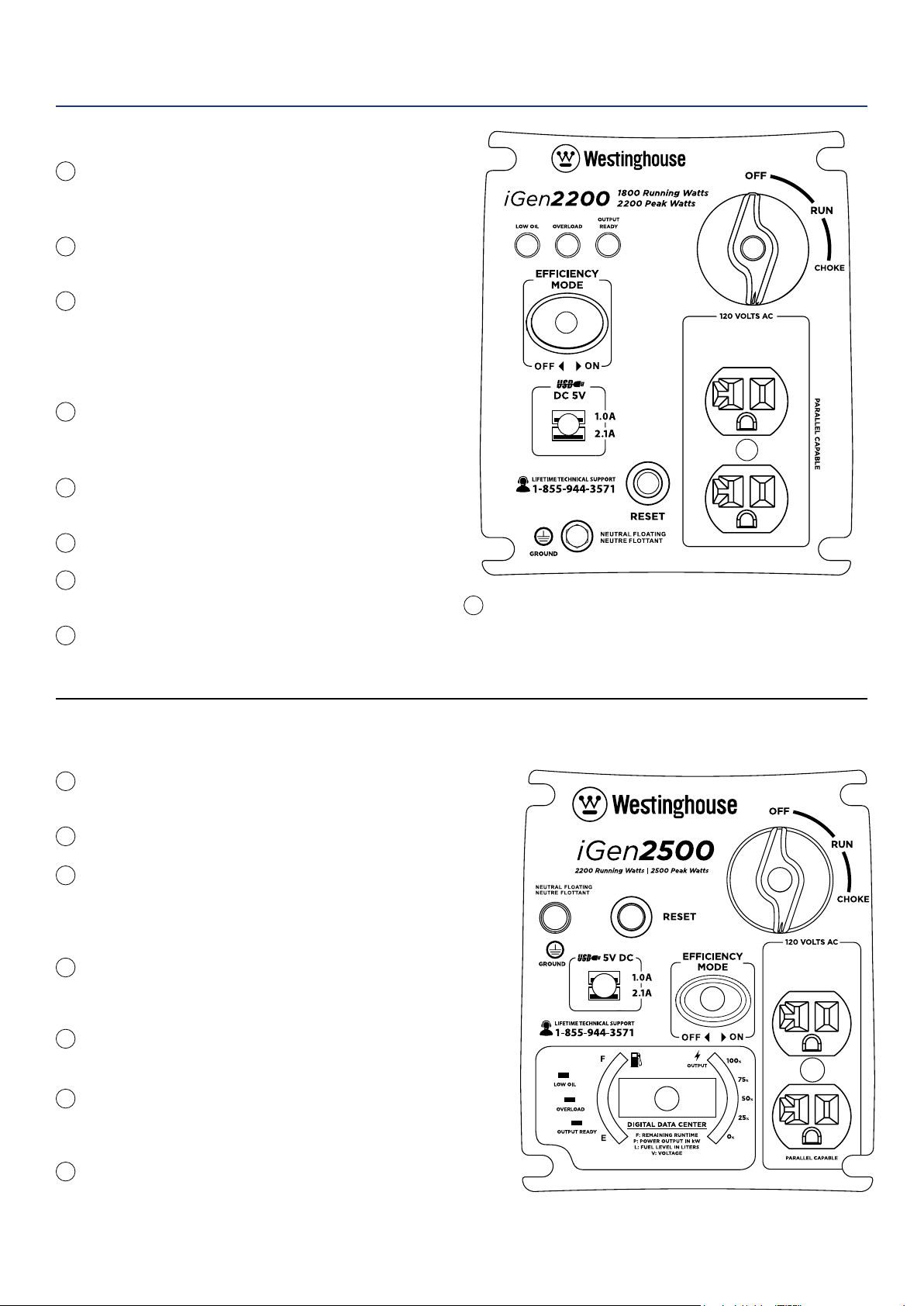
CONTROL PANEL FEATURES IGEN2200
120-Volt, 20-Amp Duplex Outlet (NEMA 5-20R):
The outlet is capable of carrying a maximum of
20 amps.
USB Duplex: 5V DC that come in 1 amps and
2.1 amps.
Reset Breaker: If the inverter is overloaded, the
reset breaker will trip. The engine will continue to
run, but there will be no output from the inverter.
Unplug the devices and reduce the load. Push in
the reset breaker to reset it.
Eciency Mode Switch: When turned to the ON
position, the engine will sense the load needed
and run at a slower RPM to save fuel.
Ground Terminal: The ground terminal is used to
externally ground the inverter.
Low Oil LED: Indicates low oil level.
Overload LED: Indicates that the inverter is
overloaded.
Output Ready LED: Indicates the inverter is
ready to be used.
1
2
3
4
5
6
7
8
9
Engine Control Switch: Turn position to CHOKE to start
the engine, and turn to RUN position once the engine is
running. Switch to OFF to stop inverter.
1
2
3
9
4
5
7
8
6
FEATURES
CONTROL PANEL FEATURES IGEN2500
120-Volt, 20-Amp Duplex Outlet (NEMA 5-20R): The
outlet is capable of carrying a maximum of 20 amps.
USB Duplex: 5V DC that come in 1 amps and 2.1 amps.
Reset Breaker: If the inverter is overloaded, the reset breaker
will trip. The engine will continue to run, but there will be no
output from the inverter. Unplug the devices and reduce the
load. Push in the reset breaker to reset it.
Eciency Mode Switch: When turned to the ON position, the
engine will sense the load needed and run at a slower RPM to
save fuel.
Ground Terminal: The ground terminal is used to externally
ground the inverter.
Engine Control Switch: Turn position to CHOKE to start the
engine, and turn to RUN position once the engine is running.
Switch to OFF to stop inverter.
LED Data Center: Indicates low oil, overload and output ready.
Displays fuel level, power output, remaining run time, voltage.
See more information on the next page.
1
2
3
4
5
6
7
1
2
3
6
4
7
5
10 | Westinghouse Portable Power
FEATURES
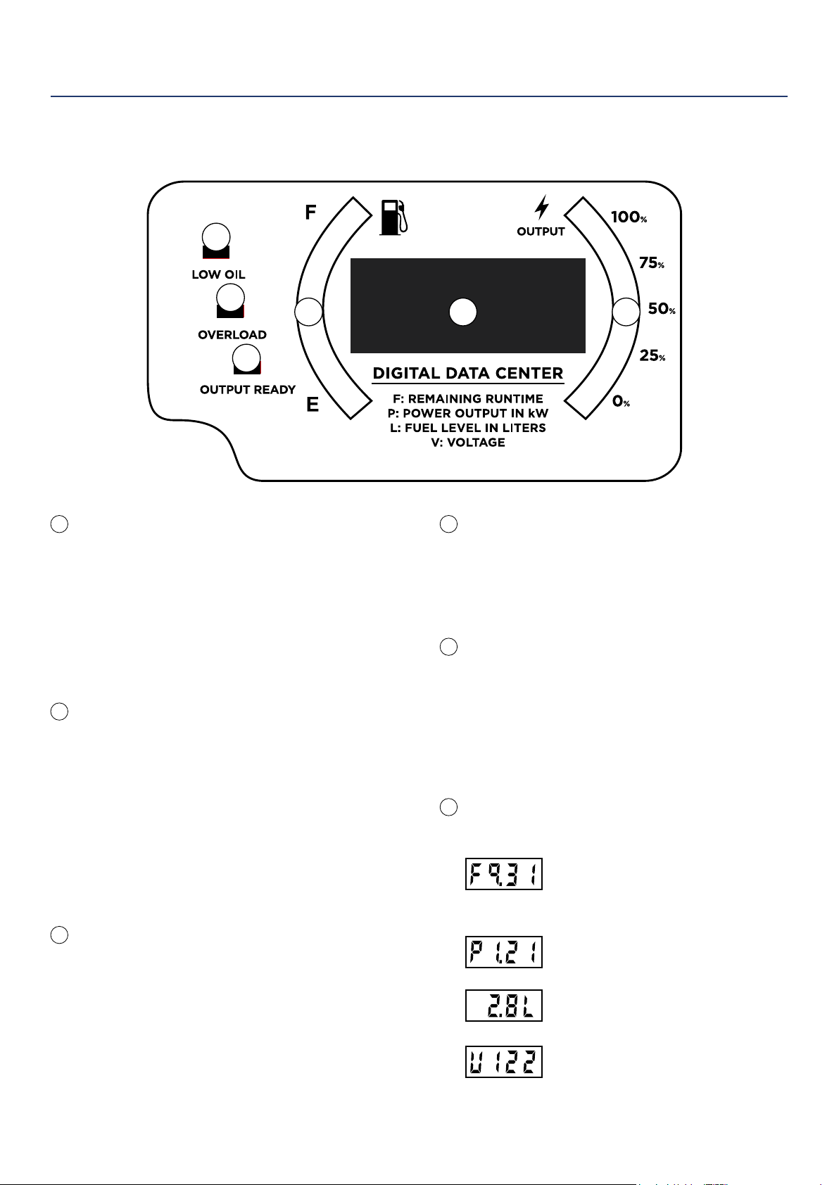
iGen2500 LED Data Display
LOW OIL INDICATOR
Description:
Lights up red when unit is low or out of oil. Engine
will not run when indicator is lit.
Recommended Action:
When this light appears conrm engine is o, let
the unit cool down, then add oil. Make sure to
periodically check oil levels while lling to prevent
overlling.
OVERLOAD INDICATOR
Description:
Red light ashes when the unit is close to
overloading. If any more load is added when the
light is ashing the electrical power will be cut to the
receptacles and light will become a constant red.
Recommended Action:
While the engine is running, disconnect all
appliances and hit the RESET breaker on the panel.
Reduce the amount of appliances before plugging
back in.
OUTPUT READY INDICATOR
Description:
The output ready indicator shows a green light
when the generator is operating normally and
producing electrical power to the receptacles.
FUEL LEVEL INDICATOR
Description:
Displays estimated fuel level percentage. Four green
lights indicate a full tank. One green light indicates
the unit is almost out of fuel. For accurate fuel levels
refer to “L” number in display.
ELECTRICAL POWER OUTPUT TO
RECEPTACLES
Description:
Displays percentage of power
output to the receptacles. A red light will display
next to the “100%” if the unit is close to being
overloaded. For accurate power output refer to
the “P” number in display.
AUTOMATIC ROTATING DATA
NUMBER DISPLAY
Remaining Run Time (F):
Displays time remaining with current
fuel level and power output. Does not
display lifetime hours.
Power Output (P):
Displays electrical power output to
receptacles in kilowatts.
Fuel level (L):
Displays current fuel level in liters.
Voltage (V):
Displays current voltage output of
generator.
1
1
4 56
2
3
2
3
4
5
6
Westinghouse Portable Power | 11
Weather – Never operate your inverter outdoors during
rain, snow or any combination of weather conditions that
could lead to moisture collecting on, in or around the
generator.
Dry Surface – Always operate the inverter on a dry
surface free of any moisture.
No Connected Loads – Make sure the inverter has no
connected loads before starting it. To ensure there are no
connected loads, unplug any electrical extension cords
that are plugged into the control panel receptacles.
NOTICE
Starting the inverter with loads already applied to
it could result in damage to any appliance being
powered o the inverter during the brief start-up
period.
Grounding the iGen Inverters
Consult with your local municipalities for your
grounding codes.
WARNING
Be sure the inverter is properly
connected to earth ground before
operating.
BEFORE STARTING THE INVERTER
BEFORE STARTING THE INVERTER,
REVIEW SAFETY SECTION STARTING
ON PAGE 5.
Location Selection – Before starting the inverter, avoid
exhaust and location hazards by verifying:
• You have selected a location to operate the inverter
that is outdoors and well ventilated.
• You have selected a location with a level and solid
surface on which to place the inverter.
• You have selected a location that is at least 6 feet
(1.8 m) away from any building, other equipment or
combustible material.
• If the inverter is located close to a building, make
sure it is not located near any windows, doors and/
or vents.
WARNING
Always operate the inverter on a level
surface. Placing the inverter on non
level surfaces can cause the inverter
to tip over, causing fuel and oil to spill.
Spilled fuel can ignite if it comes in
contact with an ignition source such
as a very hot surface.
NOTICE
Only operate the inverter on a solid, level surface.
Operating the inverter on a surface with loose
material such as sand or grass clippings can cause
debris to be ingested by the inverter that could:
• Block cooling vents
• Block air intake system
OPERATION
12 | Westinghouse Portable Power
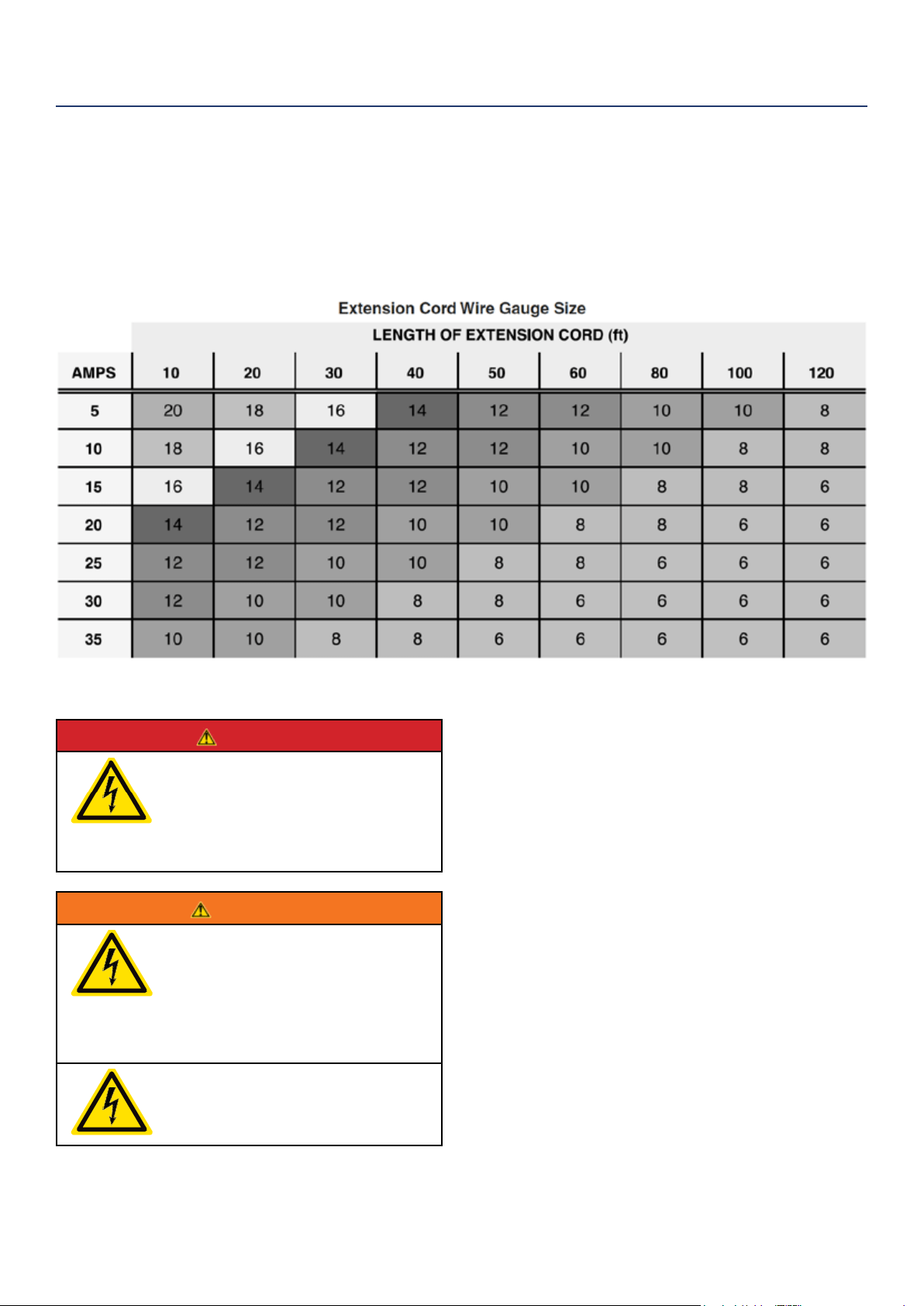
POWERCORD
Using Extension Cords
Westinghouse Portable Power assumes no responsibility for the content within this table. The use of this table is the
responsibility of the user only. This table is intended for reference only. The results produced by using this table are
not guaranteed to be correct or applicable in all situations as the type and construction of cords are highly variable.
Always check with local regulations and a licensed electrician prior to installing or connecting an electrical appliance
INVERTER PARALLELING OPERATION
DANGER
Never connect the paralleling cord
to the inverters with the inverters
running. The inverters must not be
running and both the paralleling cord
switches must be o when connecting
the cords.
WARNING
Do not attempt to parallel the
Westinghouse inverter with any other
manufacturers’ inverters. Do not use
the paralleling cord for any application
other than inverter paralleling. Do not
use this cord on other manufacturers’
inverters.
Always ensure that both ends of
the paralleling cord are switched o
before connecting the inverters.
INVERTER PARALLELING OPERATION
1. Using only the Westinghouse paralleling cord (Part
No. 260041) with both cord switches set to OFF
(O), connect one male plug to one inverter and
connect the remaining plug into the other inverter.
Either of the receptacles on the inverters can be
used.
2. Start one of the inverters and wait until the output
ready light is on.
3. Turn both cord switches to ON (I).
4. Start the remaining inverter; wait until the output
ready light is on before connecting the load.
5. When power is present, a light will illuminate in the
three-prong plug that is plugged into the inverter.
6. To stop the inverters, unplug all connected loads,
turn both cord switches to OFF (O) and unplug the
cord on each inverter.
7. If during operation the inverters’ output is stopped
due to overloading, reduce the connected load by
unplugging appliances, and then push the reset
button and restart the inverter. When the ready light
is on, the load can be reconnected.
OPERATION
Westinghouse Portable Power | 13
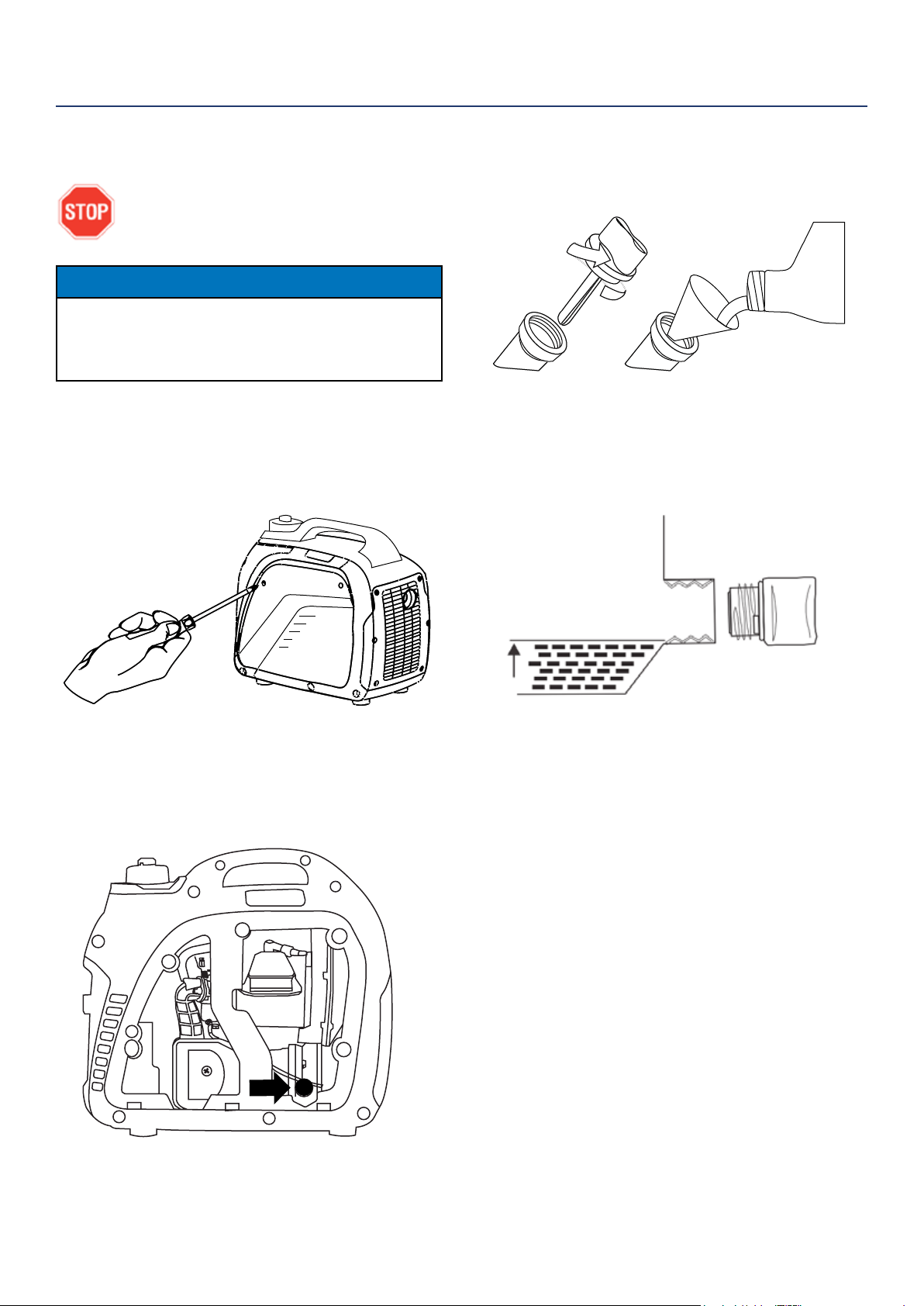
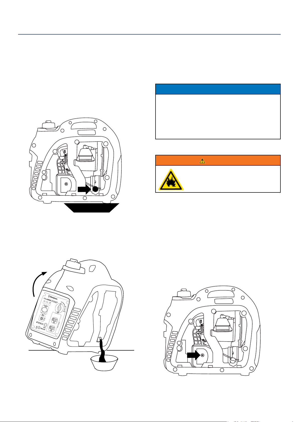
3. Using the supplied funnel and oil, pour the entire
bottle of oil into the engine (see Figure 3).
Figure 3: Oil Funnel
4. Do not overll, if oil level is too high, oil will drain
out through the ll plug. See correct oil level in
Figure 4.
Figure 4: Engine Oil Correct Level
INITIAL OIL FILL
BEFORE ADDING ENGINE OIL, REVIEW
SAFETY SECTION STARTING ON PAGE 5.
NOTICE
Engine oil must be added when the inverter is on a
at, level surface, or an inaccurate reading may result.
Do not overll. If the engine is overlled with oil, it can
cause serious engine damage.
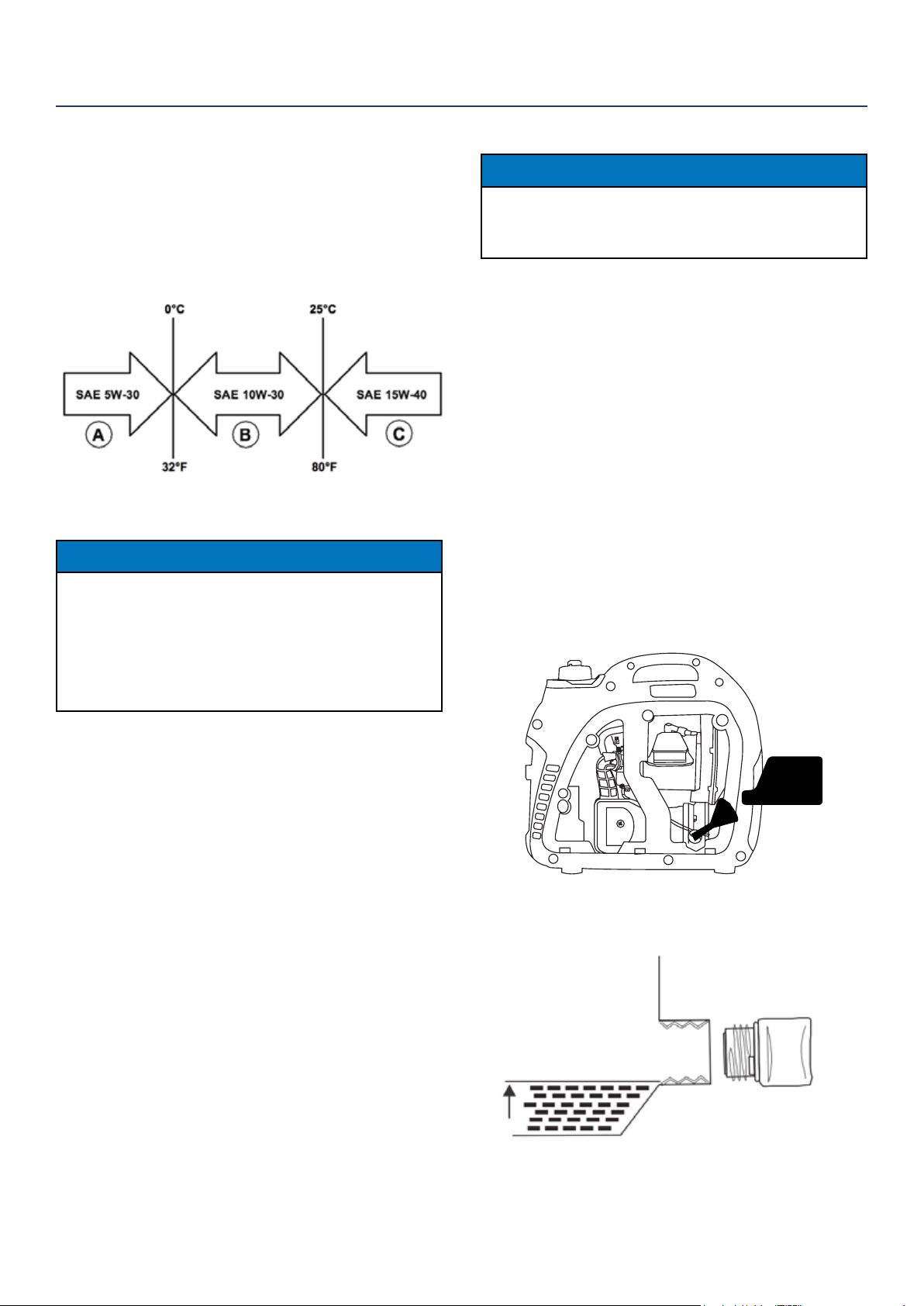
1. Loosen the screw and remove the engine oil ll/
drain plug service panel to access the oil ll/drain
plug (see Figure 1)
Figure 1: Engine Service Panel
2. Clean the area around the oil ll/drain plug and
remove plug (See Figure 2).
Figure 2: Oil Fill/Drain Plug
OPERATION
14 | Westinghouse Portable Power
ADDING/CHECKING ENGINE
FLUIDS AND FUEL
BEFORE ADDING/CHECKING ENGINE
FLUIDS AND FUEL, REVIEW SAFETY
SECTION STARTING ON PAGE 5.
DANGER
Filling the fuel tank with gasoline while
the inverter is running can cause
gasoline to leak and come in contact
with hot surfaces that can ignite the
gasoline.
Before starting the inverter, always check the level of:
• Engine oil
• Gasoline in the fuel tank
Once the inverter is started and the engine gets warm,
it is not safe to add gasoline to the fuel tank or engine
oil to the engine while the engine is running or the en-
gine and muer are hot.
CHECKING AND / OR ADDING ENGINE OIL
WARNING
Internal pressure can build in the
engine crankcase while the engine
is running. Removing the oil ll plug/
dipstick while the engine is hot can
cause extremely hot oil to spray out of
the crankcase and can severely
burn skin. Allow engine oil to cool for
several minutes before removing the
oil ll plug/dipstick.
The unit as shipped does not contain oil in the engine.
You must add engine oil before starting the inverter
for the rst time. See Initial Oil Fill on page 13 for
instructions on checking engine oil level and the
procedure for adding engine oil.
NOTICE
The engine does not contain engine oil as shipped.
Attempting to start the engine without adding
engine oil will permanently damage internal engine
components.
The engine is equipped with a low oil shutdown
switch. If the oil level becomes low, the engine may
shut down and not start until the oil is lled to the
proper level.
The owner of the inverter is responsible to ensure the
proper oil level is maintained during the operation of
the generator. Failure to maintain the proper oil level
can result in engine damage.
ADDING GASOLINE TO THE FUEL TANK
WARNING
Never refuel the inverter while the
engine is running.
Always turn the engine o and allow
the inverter to cool before refueling.
CAUTION
Avoid prolonged skin contact with
gasoline. Avoid prolonged breathing of
gasoline vapors.
Required Gasoline – Only use gasoline that meets the
following requirements:
• Unleaded gasoline only
• Gasoline with maximum 10% ethanol added
• Gasoline with an 87 octane rating or higher
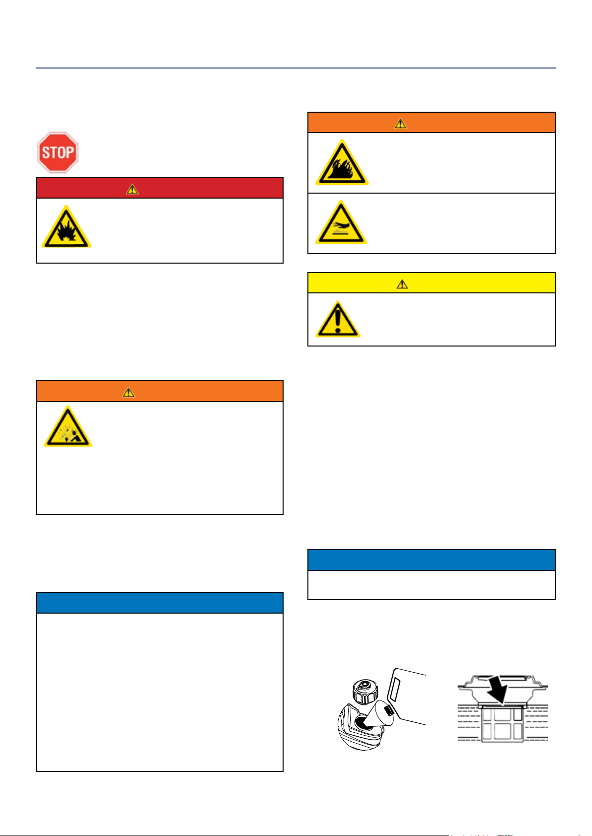
Filling the Fuel Tank – Follow the steps below to ll the
fuel tank:
1. Shut o the inverter.
2. Allow the inverter to cool down so all surface areas
of the muer and engine are cool to the touch.
3. Move the inverter to a at surface.
4. Clean area around the fuel cap.
5. Remove the fuel cap by rotating counterclockwise.
NOTICE
Do not overll the fuel tank. Spilled fuel will damage
some plastic parts.
6. Slowly add gasoline into the fuel tank. Be very care-
ful not to overll the tank. The gasoline level should
NOT be higher than the red ring (see Figure 5).
7. Install the fuel cap by rotating clockwise.
Figure 5: Maximum Gasoline Fill Level
OPERATION
Westinghouse Portable Power | 15
STARTING THE INVERTER
BEFORE STARTING THE INVERTER,
REVIEW SAFETY SECTION STARTING
ON PAGE 5.
For proper starting and operation of the inverter,
make sure you review the inverter features and their
descriptions starting on page 8.
Before attempting to start the inverter, verify the
following:
• The engine is lled with engine oil (see Figure 4:
Engine Oil Correct Level on page 13).
• The inverter is situated in a proper location (see
Location Selection on page 11).
• The inverter is on a dry surface (see Weather and Dry
Surface on page 11).
• All loads are disconnected from the inverter (see No
Connected Loads on page 11).
• The inverter is properly grounded (see Grounding the
Inverter on page 11)
DANGER
Never use the inverter in a location
that is wet or damp. Never expose
the inverter to rain, snow, water
spray or standing water while in use.
Protect the inverter from all hazardous
weather conditions. Moisture or ice
can cause a short circuit or other
malfunction in the electrical circuit.
Never operate the inverter in an
enclosed area. Engine exhaust
contains carbon monoxide. Only
operate the inverter outside and away
from windows, doors and vents.
OPERATION
Starting iGen2200 & iGen2500
1. Check oil levels. If it is the rst time starting make
sure to add oil (see Initial Oil Fill on page 13).
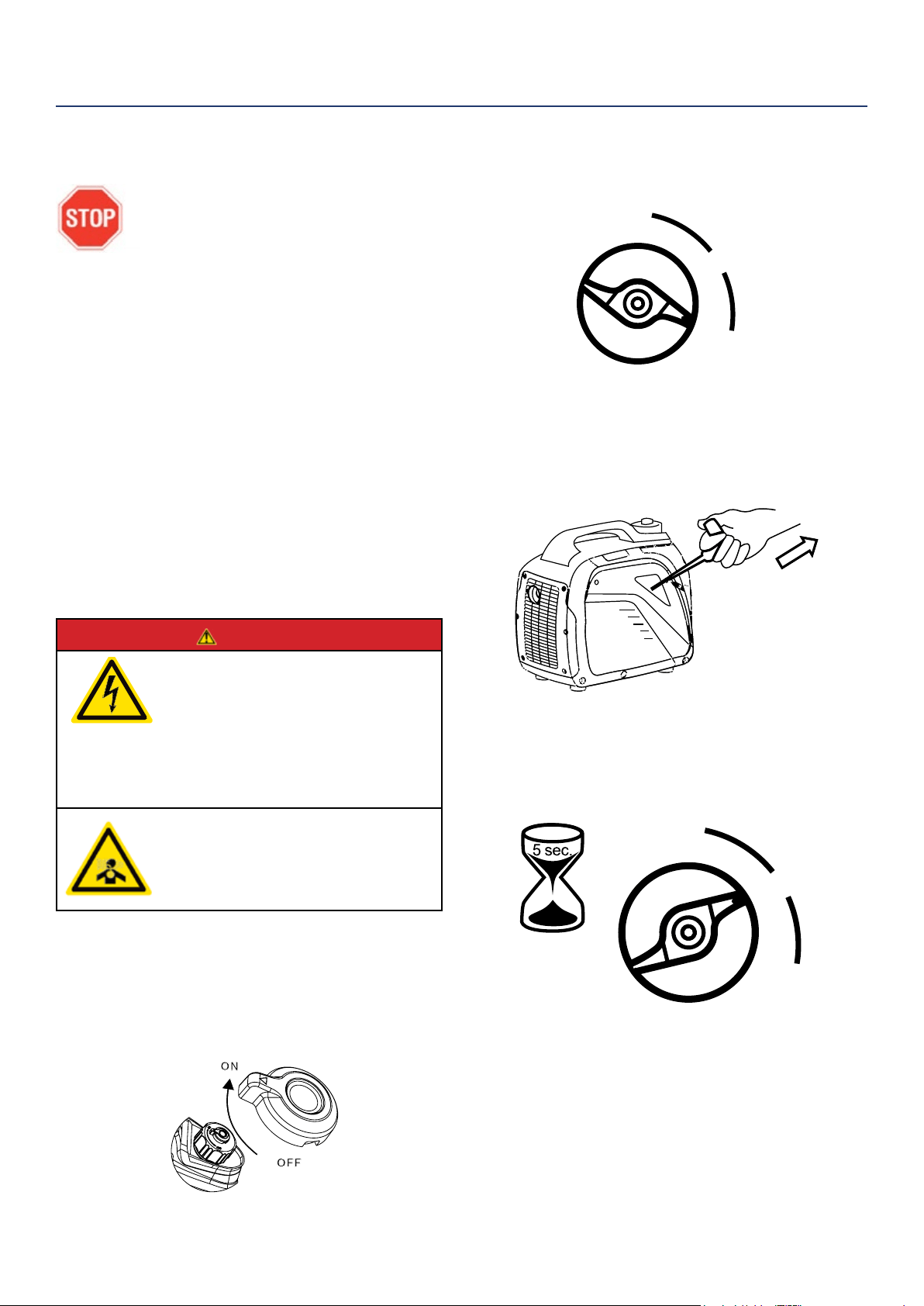
2. Turn the fuel tank vent to the ON position
(iGen2200 only) (see Figure 6).
3. Turn the engine/fuel control switch to the CHOKE
position (see Figure 7).
Figure 7: Turn Engine/Fuel Switch to CHOKE Position
4. Firmly grasp and pull the recoil handle slowly until
you feel increased resistance. At this point, apply
a rapid pull while pulling out from the inverter (see
Figure 8).
Figure 8: Pull the Recoil Handle out from Inverter
5. As the engine starts and stabilizes, turn the choke
switch back in to the RUN position (see Figure 9).
Figure 9: Turn Engine/Fuel Switch to RUN
Figure 6: fuel tank vent - iGen2200 only
OFF
RUN
CHOKE
OFF
RUN
CHOKE
16 | Westinghouse Portable Power
OPERATION
STOPPING THE INVERTER
Normal Operation
During normal operation, use the following steps to
stop your inverter:
1. Remove any connected loads from the control
panel receptacles.
2. Allow the inverter to run at “no load” to reduce and
stabilize engine and alternator temperatures.
3. Move the engine control switch to the OFF position
(see Figure 10) .
Figure 10: Turn Engine/Fuel Switch to OFF Position
4. Turn the fuel tank vent to the OFF position
(iGen2200 only).
During an Emergency
If there is an emergency and the inverter must be
stopped quickly, move the engine control switch to the
OFF position immediately (see Figure 10).
USING EFFICIENCY MODE
The inverter is equipped with an eciency mode switch
to minimize fuel consumption. In eciency mode, the
inverter will sense the load and adjust the engine RPM
to the current load requirements. Eciency mode
should be used only after the inverter has been warmed
up to operating temperature.
1. To turn on the eciency mode, press the switch to
the ON position).
2. If no load is present, the inverter RPM will drop
down to an idle speed.
3. As a load is applied, the inverter will sense the load
and engine RPM will increase according to the load
applied.
4. To run the inverter at maximum power and RPM,
press the eciency mode switch to the OFF
position.
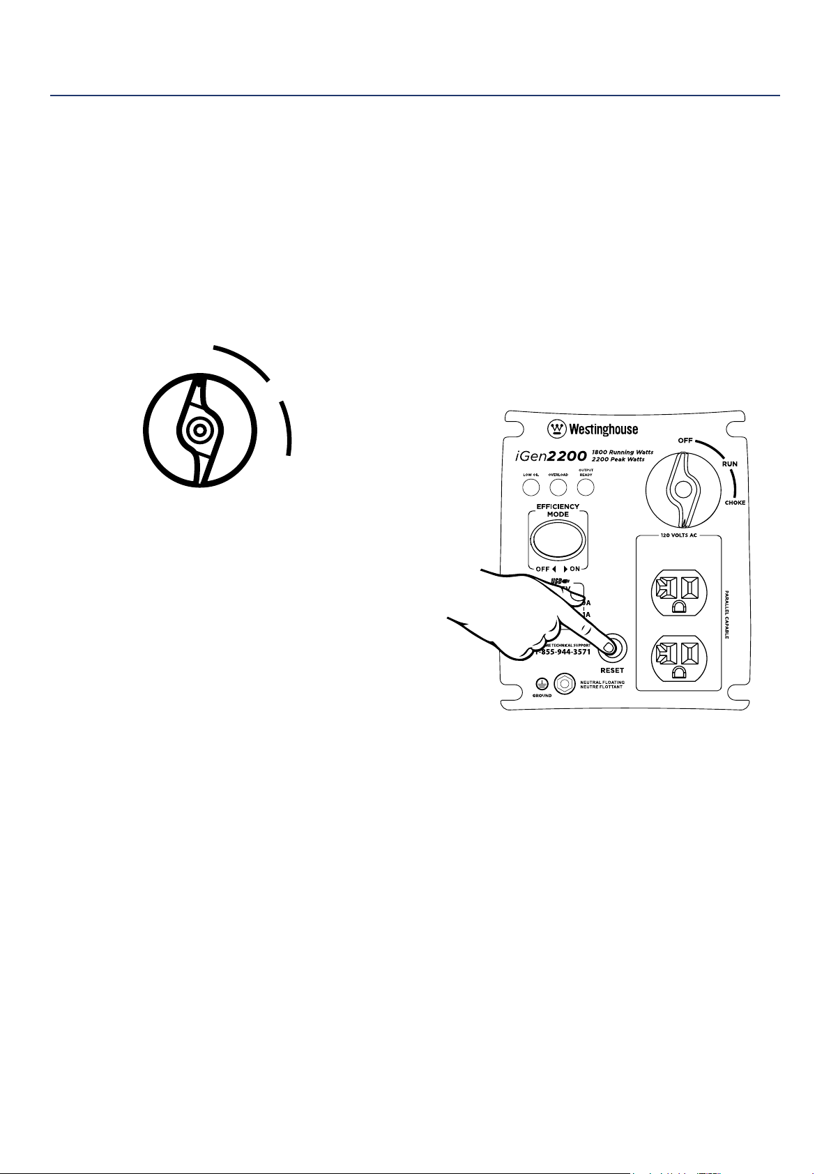
RESETTING THE RESET BREAKER
The inverter will trip the breaker and automatically
disconnect from the load when the controls sense a
predetermined overload condition. The inverter engine
will continue to run, but there will not be any electrical
output.
1. Turn o all devices and unplug them from the
inverter.
2. Determine the wattage required from the devices
being powered by the inverter. Make sure the
wattage required does not exceed the maximum
output of the inverter.
3. Press in the reset breaker to reset it (see Figure 11).
Figure 11: Press in reset breaker
4. Plug the devices in to the inverter.
5. Turn on the devices as needed.
OFF
RUN
CHOKE
Westinghouse Portable Power | 17
CAUTION
Avoid skin contact with engine oil or
gasoline. Prolonged skin contact with
engine oil or gasoline can be harmful.
Frequent and prolonged contact with
engine oil may cause skin cancer.
Take protective measures and wear
protective clothing and equipment.
Wash all exposed skin with soap and
water.
WARNING
Failure to perform periodic
maintenance or not following
maintenance procedures can cause
the inverter to malfunction and could
result in death or serious injury.
NOTICE
Periodic maintenance intervals vary depending on
inverter operating conditions. Operating the inverter
under severe conditions, such as sustained high-
load, high-temperature, or unusually wet or dusty
environments, will require more frequent periodic
maintenance. The intervals listed in the maintenance
schedule should be treated only as a general
guideline.
WARNING
Avoid accidentally starting the inverter
during maintenance by removing
the spark plug boot from the spark
plug. For electric start inverters, also
disconnect the battery cables from the
battery (disconnect the black negative
(-) cable rst) and place the cables
away from the battery posts to avoid
arcing.
Allow hot components to cool to
the touch prior to performing any
maintenance procedure.
Internal pressure can build in the
engine crankcase while the engine
is running. Removing the oil ll plug/
dipstick while the engine is hot can
cause extremely hot oil to spray out
of the crankcase and can severely
burn skin. Allow engine oil to cool for
several minutes before removing the
oil ll plug/dipstick.
Always perform maintenance in a well-
ventilated area. Gasoline fuel and fuel
vapors are extremely ammable and
can ignite under certain conditions.
MAINTENANCE
BEFORE PERFORMING MAINTENANCE ON THE INVERTER, REVIEW THE
SAFETY SECTION STARTING ON PAGE 5, AS WELL AS THE FOLLOWING
SAFETY MESSAGES.
TABLE 1: MAINTENANCE SCHEDULE - OWNER PERFORMED
Maintenance Item
Before Every
Use
After First 20
Hours or First
Month of Use
After 50 Hours
of Use or Every
6 Months
After 100 Hour
of Use or Every
6 Months
After 300 Hours
of Use or Every
Year
Engine Oil
Check Level Change Change - -
Cooling Features
Check/Clean - - - -
Air Filter
Check - Clean* - Replace
Spark Plug
- - - Check/Clean Replace
Spark Arrestor
- - - Check/Clean -
*Service more frequently if operating in dry and dusty conditions
Following the maintenance schedule is important to keep the inverter in good operating condition. The following is a
summary of maintenance items by periodic maintenance intervals.
18 | Westinghouse Portable Power
NOTICE
Engine oil must always be checked and added when
the inverter is on a at, level surface, or an inaccurate
reading may result, causing serious engine damage.
ADDING ENGINE OIL
1. Always operate or maintain the inverter on a at
surface.
2. Stop engine if running.
3. Let engine sit and cool for several minutes (allow
crankcase pressure to equalize).
4. Remove the engine service panel to gain access to
the oil ll/drain plug.
5. Thoroughly clean around the oil ll/drain plug.
6. Remove the oil ll/drain plug.
7. Select the proper engine oil as specied in
Figure 12.
8. Using the supplied oil funnel, slowly add engine oil
to the engine. Stop frequently to check the oil level
and avoid overlling.
9. Continue to add oil until the oil is at the
correct level.
ENGINE OIL MAINTENANCE
Engine Oil Specication
1. Only use the engine oil specied in Figure 12.
2. Only use 4-stroke/cycle engine oil. NEVER USE
2-STROKE/CYCLE OIL. Synthetic oil is an
acceptable substitute for conventional oil.
Figure 12: Recommended Oil
CHECKING ENGINE OIL
NOTICE
Always maintain proper engine oil level. Failure to
maintain proper engine oil level could result in severe
damage to the engine and/or shorten the life of the
engine.
Always use the specied engine oil. Failure to use the
specied engine oil can cause accelerated wear and/
or shorten the life of the engine.
Engine oil level should be checked before every use.
1. Always operate or maintain the inverter on a at
surface.
2. Stop engine if running.
3. Let engine sit and cool for several minutes (allow
crankcase pressure to equalize).
4. Remove the engine service panel to access the oil
ll/drain plug.
5. With a damp rag, clean around the oil ll/drain plug.
6. Remove the oil ll/drain plug.
7. Check oil level: When checking the engine oil,
remove the oil ll/ drain plug.
• The oil level is acceptable if oil is visible at the
bottom of the threads of the oil ll plug.
• If oil level is low, add to the correct level using
the supplied oil ll bottle. Do not overll the oil
crankcase.
MAINTENANCE
Westinghouse Portable Power | 19
7. Allow oil to completely drain.
8. Fill crankcase with oil following the steps outlined in
Adding Engine Oil on page 18.
9. Dispose of used engine oil properly.
NOTICE
Never dispose of used engine oil by dumping the
oil into a sewer, on the ground, or into groundwater
or waterways. Always be environmentally
responsible. Follow the guidelines of the EPA or
other governmental agencies for proper disposal
of hazardous materials. Consult local authorities or
reclamation facility.
CHANGING ENGINE OIL
1. Stop the engine.
2. Let engine sit and cool for several minutes (allow
crankcase pressure to equalize).
3. Remove the engine service panel to gain access to
the oil ll/drain plug.
4. Place oil pan (or suitable container) under the oil ll/
drain plug (see Figure 13).
Figure 13: Place oil pan under oil ll/drain plug
5. With a damp rag, thoroughly clean around the oil
ll/drain plug.
6. Tilt the inverter so the oil drains down the through
into the container.
MAINTENANCE
AIR FILTER MAINTENANCE
WARNING
Never use gasoline or other ammable
solvents to clean the air lter. Use only
household detergent soap to clean the
air lter.
Cleaning the Air Filter
The air lter must be cleaned after every 50 hours of
use or 3 months (frequency should be increased if
inverter is operated in a dusty environment).
1. Turn o the inverter and let it cool for several
minutes if running.
2. Remove the engine service panel to gain access to
the air lter.
3. Unscrew the air cleaner cover and tip the cover
down (see Figure 15)
4. Remove the foam element from the air cleaner
housing.
oil pan
Figure 14: Carefully tip inverter so oil ows into oil pan
Figure 15: Unscrew air cleaner cover
20 | Westinghouse Portable Power
5. Wash the foam air lter element by submerging
the element in a solution of household detergent
soap and warm water. Slowly squeeze the foam to
thoroughly clean.
NOTICE
NEVER twist or tear the foam air lter element
during cleaning or drying. Only apply slow but rm
squeezing action.
6. Rinse in clean water by submerging the air lter el-
ement in fresh water and applying a slow squeezing
action (see Figure 16).
Figure 16
NOTICE
Never dispose of soap cleaning solution used to
clean the air lter by dumping the solution into
a sewer, on the ground, or into ground water or
waterways. Always be environmentally responsible.
Follow the guidelines of the EPA or other
governmental agencies for proper disposal of
hazardous materials. Consult local authorities or
reclamation facility.
7. Dispose of used soap cleaning solution properly.
8. Dry the air lter element by again applying a slow
rm squeezing action.
9. Return the air lter element to its position in the air
cleaner housing.
10. Install the air cleaner cover, making sure the tabs
lock into place.
11. Install the engine service panel.
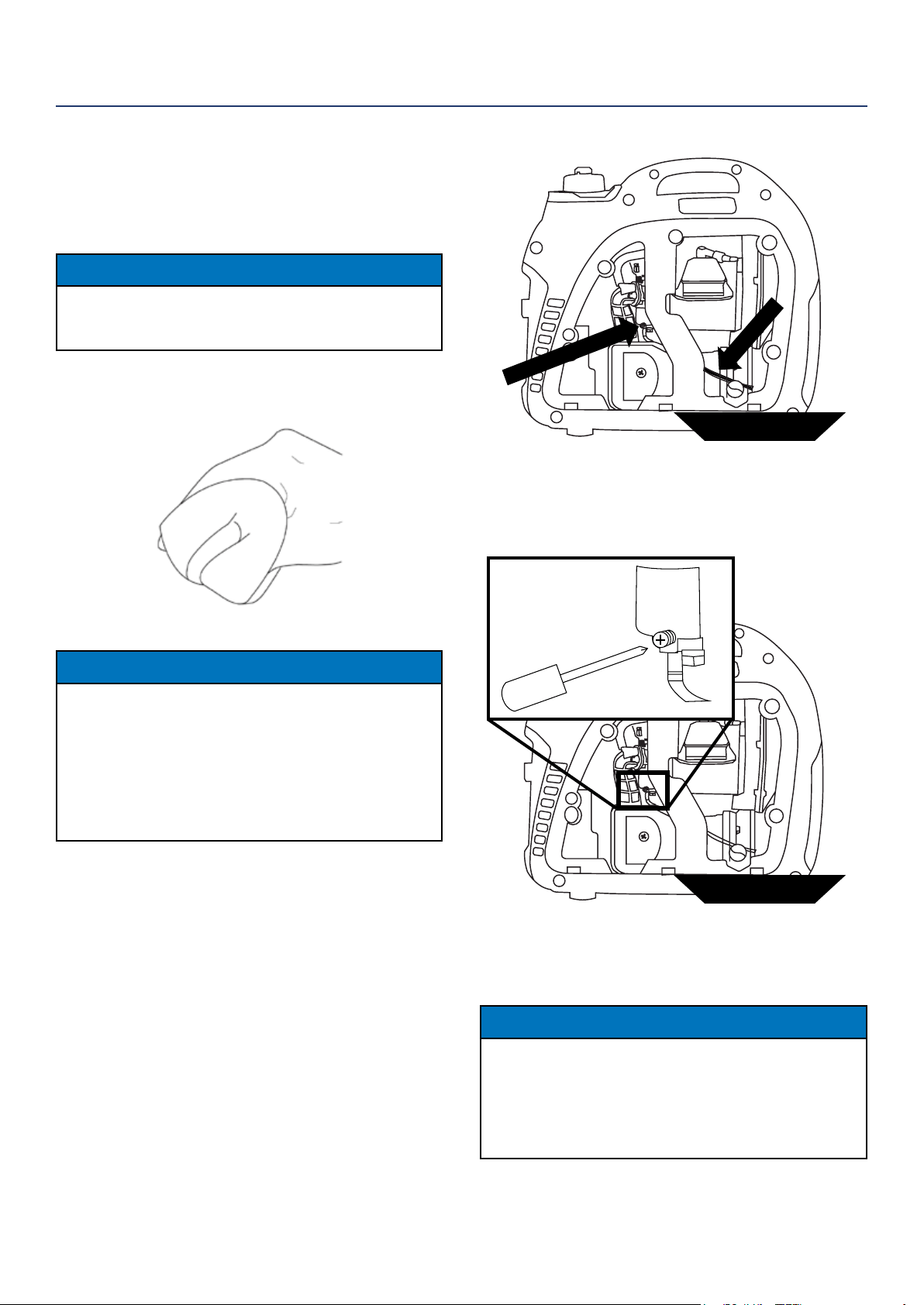
DRAINING THE FLOAT BOWL
1. Remove the engine service panel to access the
carburetor.
2. Locate the clear plastic hose from the oat that is
exiting out the bottom of the inverter, and place a
suitable container under it to catch the drained fuel
(see Figure 17).
MAINTENANCE
3. Loosen the oat bowl drain screw (see Figure 18)
until fuel is seen draining from the oat bowl.
4. Allow fuel to drain into the container, and then
tighten the oat bowl drain screw.
NOTICE
Never dispose of fuel by dumping fuel into a sewer,
on the ground, or into groundwater or waterways.
Always be environmentally responsible. Follow the
guidelines of the EPA or other governmental agencies
for proper disposal of hazardous materials. Consult
local authorities or reclamation facility.
5. Install the engine service panel.
Figure 17: Fuel drain hose
fuel pan
Fuel Drain Hose
Float Bowl Drain Screw
Figure 18: Loosen oat bowl screw
fuel pan
Westinghouse Portable Power | 21
SPARK PLUG MAINTENANCE
The spark plug must be checked and cleaned after ev-
ery 100 hours of use or 6 months and must be replaced
after 300 hours of use or every year.
1. Stop the inverter and let it cool for several minutes
if running.
2. Move the inverter to a at, level surface.
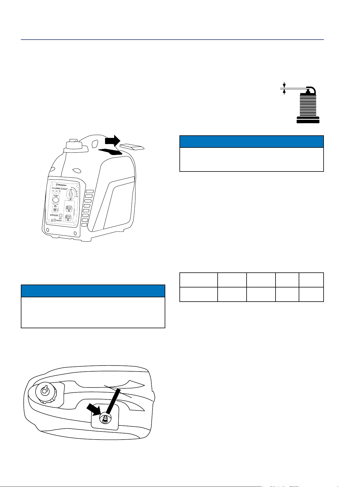
3. Slide the spark plug access cover o the housing
(see Figure 19).
4. Remove the spark plug boot by rmly pulling the
plastic spark plug boot handle directly away from
the engine.
NOTICE
Never apply any side load or move the spark plug
laterally when removing the spark plug. Applying a
side load or moving the spark plug laterally may crack
and damage the spark plug boot.
5. Clean area around the spark plug.
6. Using the spark plug socket wrench provided,
remove the spark plug from the cylinder head (see
Figure 20).
MAINTENANCE
7. Place a clean rag over the opening created by the
removal of the spark plug to make sure no dirt can
get into the combustion chamber.
8. Inspect the spark plug for:
• Cracked or chipped insulator
• Excessive wear
• Spark plug gap of 0.032 in. (0.80 mm).
If the spark plug fails any one of the
conditions listed above, replace the plug.
NOTICE
Only use the recommended spark plug. See chart
below. Using a non- recommended spark plug could
result in damage to the engine.
9. Install the spark plug by carefully following the
steps outlined below:
a. Carefully insert the spark plug back into the
cylinder head. Hand-thread the spark plug until
it bottoms out.
b. Using the spark plug socket wrench provided,
turn the spark plug to ensure it is fully seated.
c. Replace the spark plug boot, making sure the
boot fully engages the spark plug’s tip.
d. Install the spark plug access cover.
Recommended Spark Plug Replacement:
Westinghouse
Model Number
Torch Spark
plug
Champion Bosch Autolite
iGen2200
iGen2500
E6RTC RL12Y W6B 284
SPARK PLUG GAP
Figure 19: Slide o spark plug cover
Figure 20: Remove spark plug with socket wrench
22 | Westinghouse Portable Power
CHECKING AND ADJUSTING VALVE LASH
CAUTION
Checking and adjusting valve lash
must be done when the engine is cold.
1. Remove the rocker arm cover and carefully remove
the gasket. If the gasket is torn or damaged, it must
be replaced.
2. Remove the spark plug so the engine can be
rotated more easily.
3. Rotate the engine to top dead center (TDC) of the
compression stroke. Looking through the spark
plug hole, the piston should be at the top.
4. Both the rocker arms should be loose at TDC on
the compression stroke. If they are not, rotate the
engine 360°.
5. Insert a feeler gauge between the rocker arm and
the push rod and check for clearance (see Figure
22). See Table 2 for valve lash specications
Figure 22
(1) Push Rod, (2) Feeler Gauge Area
(3) Rocker Arm, (4) Jam Nut, (5) Adjusting Nut
Table 2: Standard Valve Lash
Intake Valve Exhaust Valve
Valve Lash
.0023-.0039in
(.06-.10mm)
.0031-.0048in
(.08-.12mm)
Bolt Torque
8-12N.m 8-12N.m
6. If an adjustment is required, hold the adjusting nut
and loosen the jam nut.
7. Turn the adjusting nut to obtain the correct valve
lash. When the valve lash is correct, hold the ad-
justing nut and tighten the jam nut to 106 in-lb (12
N•m).
8. Recheck the valve lash after tightening the jam nut.
9. Perform this procedure for both the intake and
exhaust valves.
10. Install the rocker arm cover, gasket and spark plug.
MAINTENANCE
CLEANING THE SPARK ARRESTOR
Check and clean the spark arrestor after every 100
hours of use or 6 months.
1. Stop the inverter and let it cool for several minutes
if running.
2. Move the inverter to a at, level surface.
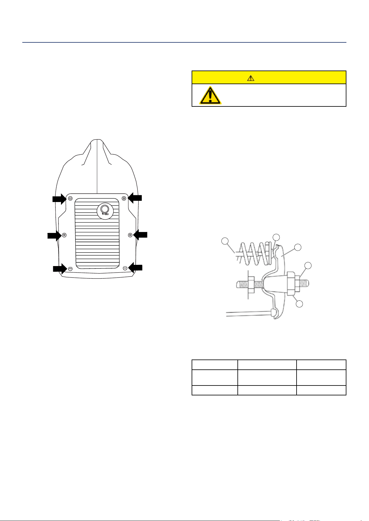
3. Remove the screws holding the muer cover in
place (see Figure 21).
4. Loosen the clamp holding the spark arrestor onto
the muer.
5. Slide the spark arrestor band clamp o the spark
arrestor screen.
6. Pull the spark arrestor screen o the muer
exhaust pipe.
7. Using a wire brush, remove any dirt and debris that
may have collected on the spark arrestor screen.
8. If the spark arrestor screen shows signs of wear
(rips, tears or large openings in the screen), replace
the spark arrestor screen.
9. Install the spark arrestor components in the
following order:
a. Place spark arrestor screen over the muer
exhaust pipe. Push on the screen until it fully
bottoms out.
b. Place the spark arrestor band clamp over the
screen and tighten with a athead screwdriver
10. Replace the discharge gate.
Figure 21: Remove screws holding muer cover
1
2
3
4
5
Westinghouse Portable Power | 23
Proper care should be taken to prepare the inverter for
any storage
1. Clean the inverter as outlined in Cleaning the
Inverter.
2. Siphon all gasoline from the fuel tank as best as
possible.
3. Start the engine and allow the inverter to run until
all the remaining gasoline in the fuel lines and
carburetor is consumed and the engine shuts o.
4. Drain any remaining fuel from the oat bowl. See
Draining the Float Bowl on page 20.
5. Change the oil (see Changing Engine Oil on page
19).
6. Remove the spark plug (see Spark Plug
Maintenance on page 21) and place about 1
tablespoon of oil in the spark plug opening. While
placing a clean rag over the spark plug opening,
slowly pull the recoil handle to allow the engine to
turn over several times. This will distribute the oil
and protect the cylinder wall from corroding during
storage.
7. Replace the spark plug (see Spark Plug
Maintenance on page 21).
8. Move the inverter to a clean, dry place for storage.
CLEANING THE INVERTER
It is important to inspect and clean the inverter before
every use.
Clean All Engine Air Inlet and Outlet Ports – Make
sure all engine air inlet and outlet ports are clean of any
dirt and debris to ensure the engine does not run hot.
STORAGE
WARNING
Never store an inverter with fuel in the
tank indoors or in a poorly ventilated
area where the fumes can come in
contact with an ignition source such
as a: 1) pilot light of a stove, water
heater, clothes dryer or any other gas
appliance; or 2) spark from an electric
appliance.
NOTICE
Gasoline stored for as little as 60 days can go bad,
causing gum, varnish and corrosive buildup in fuel
lines, fuel passages and the engine. This corrosive
buildup restricts the ow of fuel, preventing an engine
from starting after a prolonged storage period.
MAINTENANCE

24 | Westinghouse Portable Power
WARNING
Before attempting to service or troubleshoot the generator, the owner or service technician must rst read the owner’s
manual and understand and follow all safety instructions. Failure to follow all instructions may result in conditions that
can lead to voiding of the EPA certication or product warranty, serious personal injury, property damage or even death.
TROUBLESHOOTING
PROBLEM POTENTIAL CAUSE SOLUTION
Engine is running, but no
electrical output.
1. Reset breaker is tripped. 1. Reset the reset breaker (see page 16).
2. The power cord’s plug connector is not fully
engaged in the inverter’s outlet.
2. Verify plug connector is rmly engaged
in the inverter’s outlet.
3. Faulty or defective power cord 3. Replace power cord.
4. Faulty or defective electrical appliance 4. Try connecting a known good appliance
to verify the inverter is producing electrical
power.
Engine will not start or remain
running while trying to start.
1. Inverter is out of gasoline. 1. Add gasoline to the inverter (see page
14).
2. Fuel ow is obstructed. 2. Inspect and clean fuel delivery passages.
3. Dirty air lter 3. Check and clean the air lter (see page
19).
4. Low oil level shutdown switch is preventing
the unit from starting.
4. Check oil level and add oil if necessary
(see page 18).
5. Spark plug boot is not fully engaged with
the spark plug tip.
5. Firmly push down on the spark plug boot
to ensure the boot is fully engaged.
6. Spark plug is faulty. 6. Remove and check the spark plug.
Replace if faulty (see pages 21).
7. Dirty/plugged spark arrestor 7. Check and clean the spark arrestor (see
page 22).
8. Stale fuel 8. Drain fuel and replace with fresh fuel.
Inverter suddenly
stops running.
1. Inverter is out of fuel. 1. Check fuel level (see page 14). Add fuel
if necessary.
2. The low oil shut down switch has stopped
the engine.
2. Check oil level and add oil if necessary
(see page 18).
3. Too much load 3. Restart the inverter and reduce the load.
Engine runs
erratic; does not hold a
steady RPM.
1. Choke was left in the CHOKE position. 1. Move choke to the RUN position
2. Dirty air lter 2. Clean the air lter (see page 19).
3. Applied loads maybe cycling on and o 3. As applied loads cycle, changes in
engine speed may occur; this is a normal
condition.
Westinghouse Portable Power | 25
iGen2200 EXPLODED VIEW
No Part Description Quantity
1 100509 Discharge Grate 1
2 100514 J Clip 10
3 130523 DC Regulator 1
4 120506 Inverter Module 1
5 170507 Starter Grip 1
7 130521 Control Panel 1
8 100503 Enclosure Side 1
9 100507 Shoulder Bolt 6
10 100535 Inspection Cover 1
11 100520 Rubber Foot 4
12 150515 Fuel Tank 1
13 150504 Splash Guard 1
14 150514 Fuel Fill Marker 1
15 150513 Fuel Cap 1
16 100505 Enclosure Side 1
17 170522 Side Panel 1
18 170505 Grip Cover 1
19 170508 Fuel Valve 1
20 100511 Rubber Boot 1
21 100517 Stop 1
22 100513 Intake Grate 1
26 | Westinghouse Portable Power
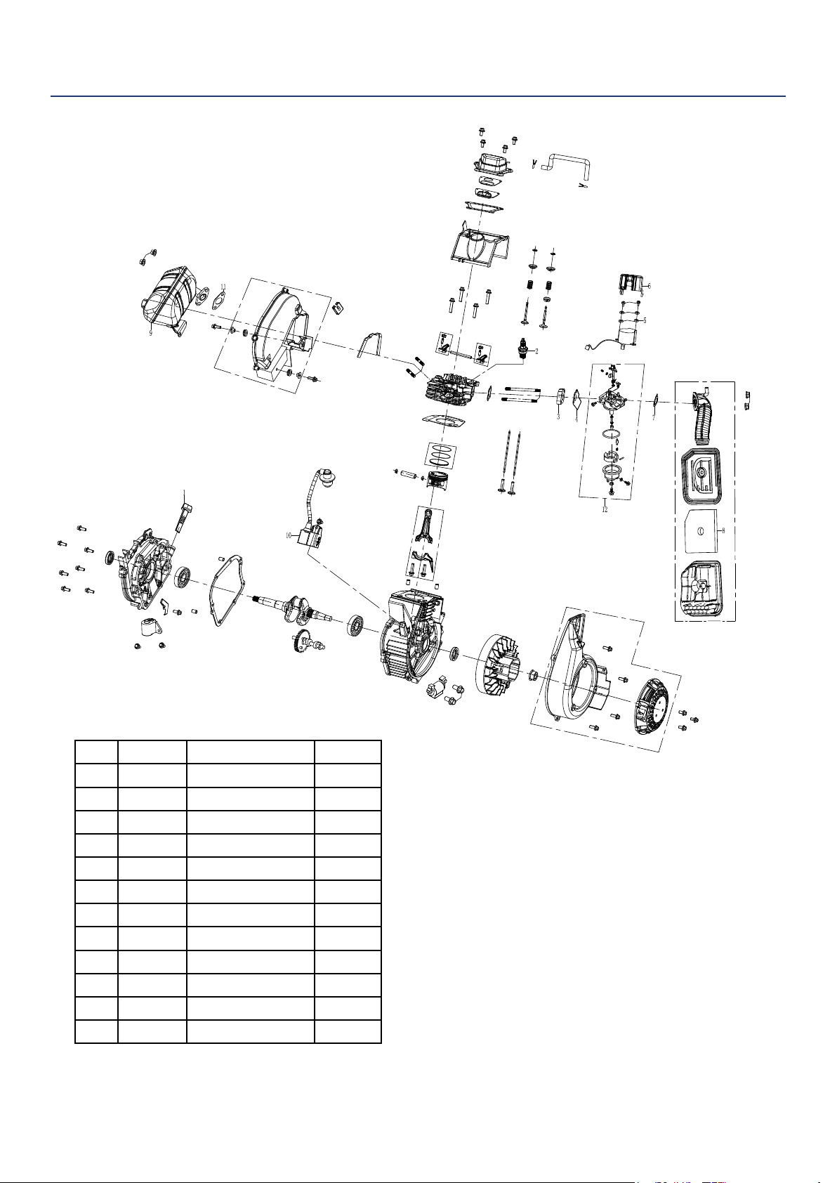
iGen2200 ENGINE VIEW
No Part Description Quantity
1 180558 Dip Stick 1
2 180532 Spark Plug 1
3 140521 Spacer 1
4 140520 Gasket 1
5 180577 Washer 1
6 140522 Stepper Motor 1
7 140523 Gasket 1
8 160503 Air Filter 1
9 110507 Muer Assy 1
10 180525 Ignition Coil 1
11 110506 Gasket 1
12 140524 Carburetor Assy 1
Westinghouse Portable Power | 27
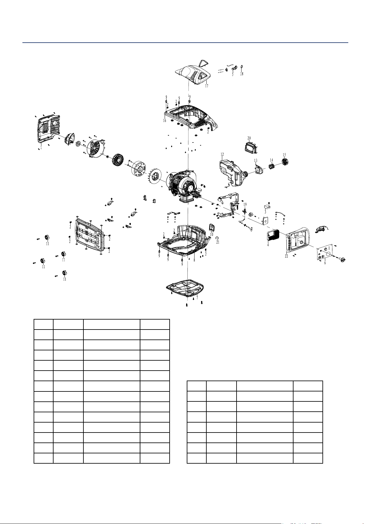
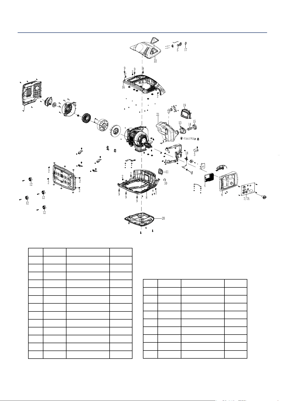
iGen2500 EXPLODED VIEW
No Part Description Quantity
1 100509 Discharge Grate 1
2 100514 J Clip 10
3 130500 DC Regulator 1
4 120500 Inverter Module 1
5 170507 Starter Grip 1
6 100519 Intake Grate 1
7 130515 Control Panel 1
7A 130516 Control Panel 1
8 100503 Enclosure Side 1
9 100507 Shoulder Bolt 6
10 100517 E Clip 1
11 100513 Inspection Cover 1
12 100520 Rubber Foot 4
13 150504 Splash Guard 1
14 150509 Fuel Fill Marker 1
15 150503 Fuel Cap 1
16 100505 Enclosure Side 1
17 170505 Grip Cover 1
18 170508 Fuel Valve 1
19 100511 Rubber Boot 1
20 100502 Side Panel 1
21 150511 Fuel Tank 1
22 100501 Side Panel 1
28 | Westinghouse Portable Power
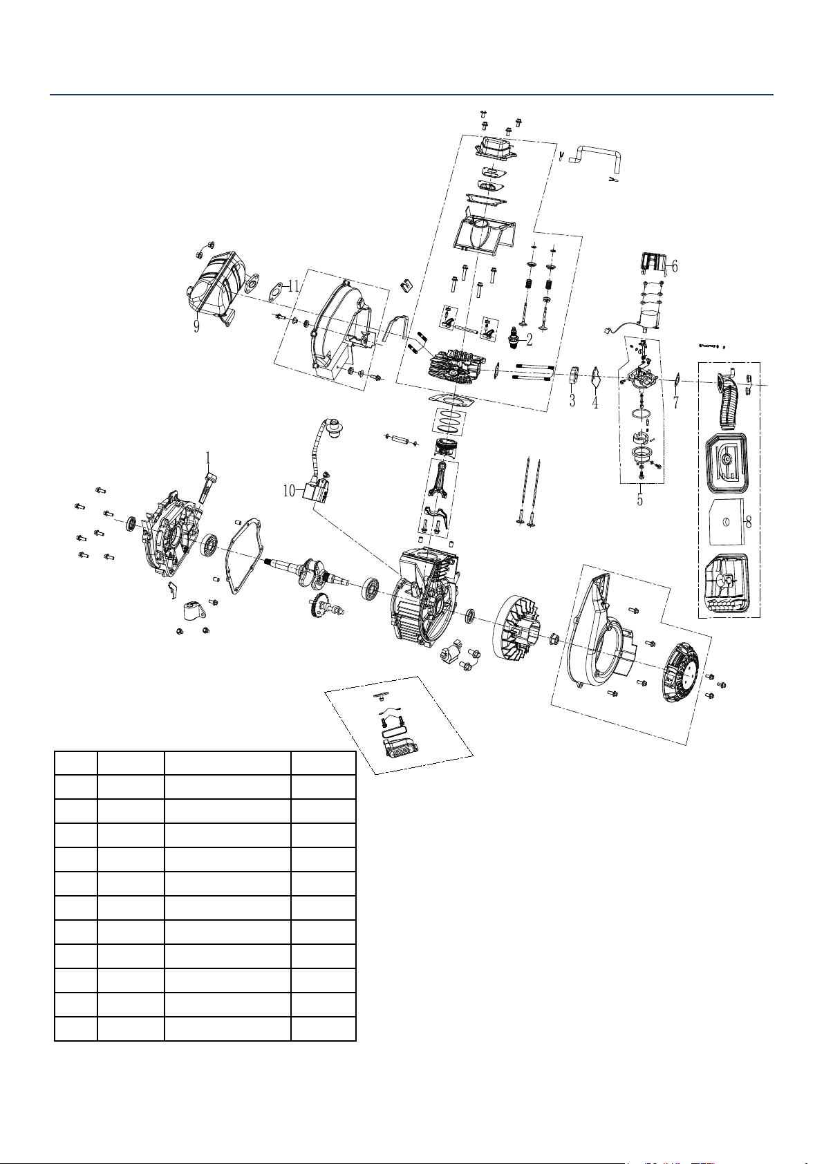
iGen2500 ENGINE VIEW
No Part Description Quantity
1
180558 Dip Stick 1
2 180532 Spark Plug 1
3 140521 Spacer 1
4 140520 Gasket 1
5 140511 Carburetor Assy 1
6 140522 Stepper Motor 1
7 140523 Gasket 1
8 160503 Air Filter 1
9 110505 Muer Assy 1
10 180525 Ignition Coil 1
11 110506 Gasket 1
Westinghouse Portable Power | 29
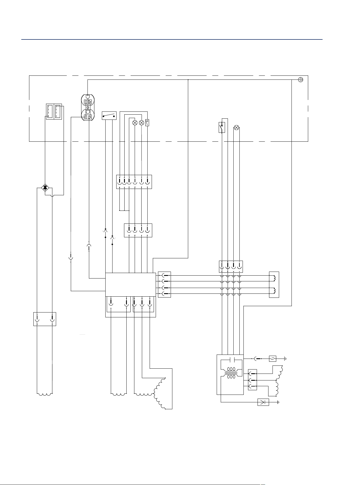
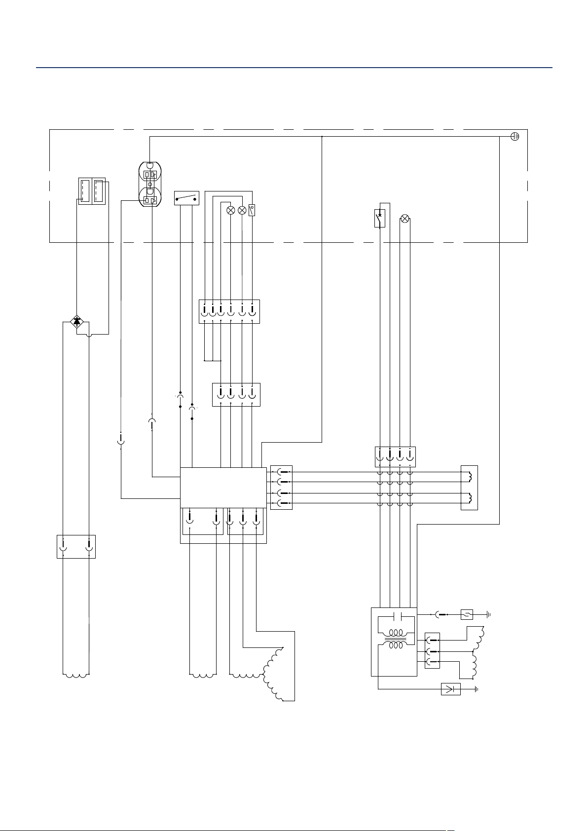
Inverter
Control
power
winding
Main
winding
DC
Winding
R
Bl
Grounding
Ignition
Oil Indicator
Stepper motor
Oil Sensor
Engine
Generator
Control Panel
Fault indicator
Running lights
Y
Bl
Br
R/W
Bl
Bl
O
Bu
R
Bu
R
W
W
W
Bu
Bu
Bu 16AWG
Bu 16AWG
R
W
W
Br
Bl
Gr
Bl
R
Y
Bu
Ignition
Coil
Idle switch
Spark
plug
Y/G
Y/G 14AWG
Bu
R
Bl
O
Flameout switch
Bl 黑色
棕色
O 橙色
Bu
蓝色
Gr
灰色
R
红色
Br
W
白色
Y/G
黄绿色
iGEN 2000 iGEN 2500电路图
1
2
3
4
USB
1
2
3
4
R
W
W
W
Y/G
Y/G
Y/G
Reset
Bl
W
Bl
W
利用 pdfFactory Pro 测试版本创建的PDF文档 www.pdffactory.com
iGen2200 SCHEMATICS
30 | Westinghouse Portable Power
Inverter
Control
power
winding
Main
winding
DC
Winding
R
Bl
Grounding
Ignition
Oil Indicator
Stepper motor
Oil Sensor
Engine
Generator
Control Panel
Fault indicator
Running lights
Y
Bl
Br
R/W
Bl
Bl
O
Bu
R
Bu
R
W
W
W
Bu
Bu
Bu 16AWG
Bu 16AWG
R
W
W
Br
Bl
Gr
Bl
R
Y
Bu
Ignition
Coil
Idle switch
Spark
plug
Y/G
Y/G 14AWG
Bu
R
Bl
O
Flameout switch
Bl 黑色
棕色
O 橙色
Bu
蓝色
Gr
灰色
R
红色
Br
W
白色
Y/G
黄绿色
iGEN 2000 iGEN 2500电路图
1
2
3
4
USB
1
2
3
4
R
W
W
W
Y/G
Y/G
Y/G
Reset
Bl
W
Bl
W
利用 pdfFactory Pro 测试版本创建的PDF文档 www.pdffactory.com
iGen2500 SCHEMATICS

Westinghouse Portable Power | 31
Maintenance Notes

32 | Westinghouse Portable Power
Version 7.12.18KD