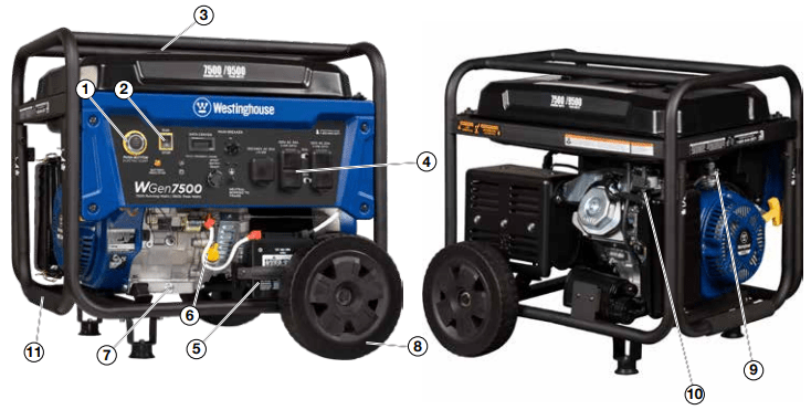
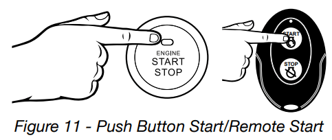
Push Button Electric Start: Starts and stops the engine.
Engine Control Switch/Battery Disconnect: Allows fuel to flow to engine and energizes the ignition system. Also, disconnects battery power when in “Stop” position.
Fuel Cap: Close until clicking sound is heard.
Control Panel: Contains the circuit breakers and outlets.
Battery: Included for electric start models.
Oil Fill Plug/Dipstick: Must be removed to add and check oil.
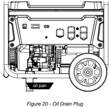
Oil Drain Plug: Must be removed to drain engine oil
Never Flat Wheels: For easy portability
Fuel Shut off Valve: Controls the flow of fuel to the engine.
Auto Choke: Battery must be hooked up for auto choke to work properly. You can manually adjust the choke if the battery is not connected.
Single Piece Handle: Includes rubber grip. Allows you to easily push or pull unit with one hand.
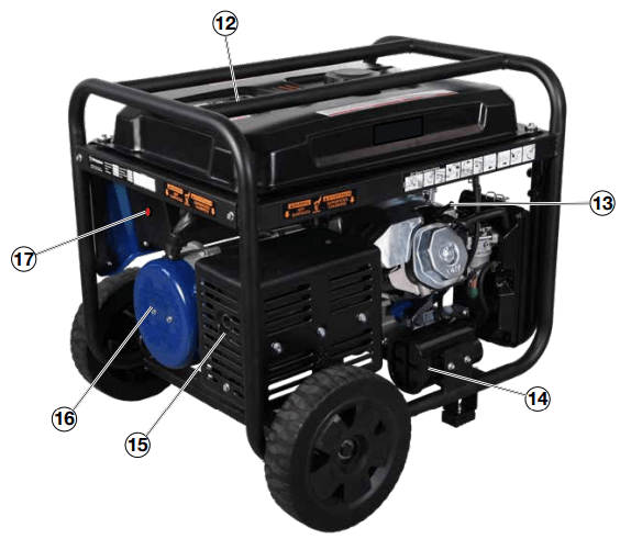
12. Fuel Gauge: Indicates fuel level.
13. Spark Plug Boot (Wire): Must be removed when servicing the engine or the spark plug.
14. CARB Canister: Required for models sold into and used in California.
15. Muffler and Spark Arrester: Avoid contact until engine is cooled down. Spark arrestor prevents sparks from exiting the muffler. It must be removed for servicing.
16. Alternator Cover: Gain access to alternator wiring.
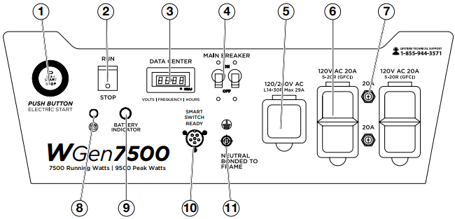
• Push for 1 second to automatically start the engine.
• Push again to stop the engine.
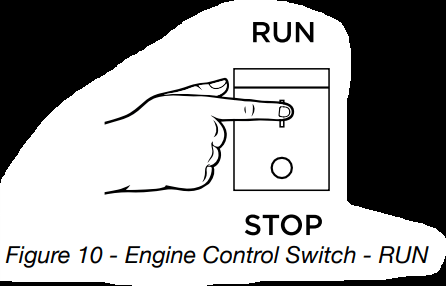
2. Engine Control Switch/Battery Disconnect: Switch to “Stop” to stop the engine. When in “Stop” position it prevents the unit from drawing power from the battery. Switch to “Run” before starting engine.
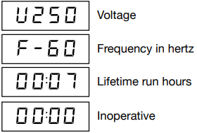
3. Data Center: The VFT Meter is 4 state LED display that will rotate through volts, frequency, and lifetime run hours. The 4th display is not used and will always display 00:00. You can press the MODE button to cycle through the different displays. The meter will display volts and hertz even if there is no load connected.
The frequency and voltage can vary +/- 5% and still be within tolerance
4. Main Circuit Breaker: The main circuit breaker controls total output of all outlets to protect the generator.
5. 120/240-Volt, 30-Amp Twist Lock Outlet (NEMA L14-30R): Outlet can supply either 120V or 240V output.
6. 120-Volt, 20-Amp Duplex GFCI Outlets (NEMA 5-20R): Each outlet is capable of carrying a maximum of 20 amps on a single receptacle or a combination of both receptacles.
7. 20-Amp Circuit Breakers: Each circuit breaker limits the current that can be delivered through the 120-volt duplex outlets to 20amps.
8. Battery Charge Port: Engine control switch must be in OFF position to charge with included charger. Used in conjunction with the Westinghouse ST Switch (sold separately) when the generator is in standby mode to charge the battery.
9. Battery Indicator Light: When light is illuminated, the battery is connected and providing power to the electronics.
10. Smart Switch Outlet: Connects the Westinghouse ST Switch (sold separately) to the control panel.
11. Ground Terminal: The ground terminal is used to ground the generator.
OPERATION
POWERCORD
Using Extension Cords
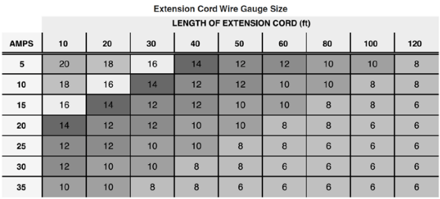
Westinghouse Portable Power assumes no responsibility for the content within this table. The use of this table is the responsibility of the user only. This table is intended for reference only. The results produced by using this table are not guaranteed to be correct or applicable in all situations as the type and construction of cords are highly variable. Always check with local regulations and a licensed electrician prior to installing or connecting an electrical appliance.
Using Westinghouse Power Cord
Use the extension cord chart to determine the size of the conductor for extension cord applications. Determine the distance of the generator to the appliance on the top line of the chart. Then select the rated amperage of the generator on the left side of the chart. Where the two meet is the size of the conductor required for the application.
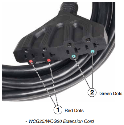
When using the WCG25/WCG20 power cord (sold separate) connect to the 120/240V outlet. The opposite end of the power cord is a fan tail receptacle with 2 green receptacles and 2 red receptacles. Each receptacle is rated at 120 volts AC. To balance the load on the generator’s alternator, use the red and green identifiers on the fan tail receptacle. To keep the load balanced, connect the loads so that both color receptacles are used. An example is one in red and one in green. Do not connect 2 in red and none in green, or 2 in green and none in red. If only one color receptacle is used with multiple loads, the alternator may experience an unbalanced load, causing undue vibration to generator.
CONNECTING THE GENERATOR TO A BUILDING ELECTRICAL SYSTEM
It is recommended to use a manual transfer switch when connecting directly to a buildings electrical system. Connecting a portable generator to a buildings electrical system must be made in strict compliance with all national and local electrical codes and laws, and be completed by a qualified electrician.
TRANSFER SWITCH CONNECTIONS
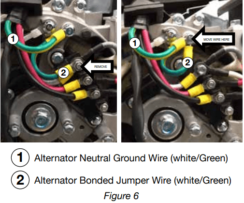
The Westinghouse generator is wired with the neutral bonded to ground. If you are connecting your generator to a panel board transfer switch, a licensed electrician will need to consider removing the bonded neutral to ensure proper operation of household GFCI circuits. Begin by removing the alternator cover (16 on page 13). Once the cover is off remove the nut that holds the bonded ground jumper wire (see “2” in Figure 6). Once the nut is removed take the bonded jumper wire off and re-secure the nut. Next remove the screw holding the neutral ground wire (see “1” in Figure 6). Attach the bonded jumper wire (2) to the neutral ground (1) and tighten the screw.
If the bonded neutral is removed the generator must be relabeled as floating neutral on the control panel.
If your generator is equipped with GFCI receptacles, removing the bonded neutral may not allow proper operation of the GFCI receptacles. Always keep the jumper wire in case it is needed for future use when not connected to a transfer switch.
ADDING / CHECKING ENGINE FLUIDS AND FUEL
Before starting the generator, always check the level of:
• Engine oil
• Gasoline in the fuel tank
Once the generator is started and the engine gets warm, it is not safe to add gasoline to the fuel tank or engine oil to the engine while the engine is running or the engine and muffler are hot.
CHECKING AND / OR ADDING ENGINE OIL
The unit as shipped does not contain oil in the engine. You must add engine oil before starting the generator for the first time. See Checking Engine Oil and Adding Engine Oil on page 24 for instructions on checking engine oil level and the procedure for adding engine oil.
NOTICE The engine does not contain engine oil as shipped. Attempting to start the engine can damage engine components. The owner of the generator is responsible to ensure the proper oil level is maintained during the operation of the generator. Failure to maintain the proper oil level can result in engine damage.
ADDING GASOLINE TO THE FUEL TANK
Required Gasoline – Only use gasoline that meets the following requirements:
• Unleaded gasoline only
• Gasoline with maximum 10% ethanol added
• Gasoline with an 87 octane rating or higher
Filling the Fuel Tank – Follow the steps below to fill the fuel tank:
Shut off the generator.
Allow the generator to cool down so all surface areas of the muffler and engine are cool to the touch.
Move the generator to a flat surface.
Clean area around the fuel cap.
Remove the fuel cap by rotating counterclockwise.
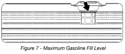
Slowly add gasoline into the fuel tank. Be very careful not to overfill the tank. The gasoline level should NOT be higher than the filler neck (see Figure 7).
Install the fuel cap by rotating clockwise until you hear a click, indicating the cap is completely installed.
BEFORE STARTING THE GENERATOR
Before attempting to start the generator, verify the following:
• The engine is filled with engine oil. See Checking Engine Oil on page 24.
• The generator is situated in a proper location (Location Selection on page 15).
• The generator is on a dry surface (Weather and Dry Surface on page 15).
• All loads are disconnected from the generator (No Connected Loads on page 15).
• The generator is properly grounded the Generator (page 15).
PROGRAMMING THE GENERATOR FOR REMOTE START
NOTICE The key fob included with the generator should come already paired with the unit. If it does not you can follow the directions below to reconnect. If your unit was shipped without a key fob please contact our customer support team.
WARNING Always make sure the area around the generator is clear of bystanders before using the remote start to start the generator.
The generator can be started remotely from up to a maximum of 109 yards (100 M) away using the remote start key fob with new, fully charged batteries in the key fob. As the batteries’ state of charge in the key fob reduces, the distance to start the generator will also reduce.
Before the generator can be started, an initial start-up procedure must be performed so the generator and the key fob recognize each other. If the key fob is replaced, you will need to go through this procedure with the new fob.
1. With the battery connected, turn the engine control switch to the RUN position. The yellow battery light will illuminate.
2. Push and hold the red REMOTE PAIRING button on the side of the control panel until the push button start (3) on the control panel illuminates red, then let go (see 17 on page 13 for location of button).
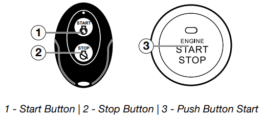
3. Press and hold the STOP (2) button on the remote start key fob until the red light on the push button start (3) goes out, then let go.
4. Press and hold the START (1) button on the remote start key fob until the red light on the push button start (3) goes out, then let go.
5. Press and hold the REMOTE PAIRING button until the red light on the push button start (3) goes out. The generator is now programmed to start remotely
POWER OUTPUT AND DEMAND
The generator should not be run completely unloaded for extended periods otherwise the engine may be damaged. It is recommended that the generator should always be operated with at least one-third of its rated 120-Volt AC power output. 120-Volt AC devices have two different electric power demands that must be taken into consideration, namely the running power and the starting/peak power. Both are measured in Watts (typically abbreviated as “W”).
The steady state continuous load is the running power demand and this is often marked on the device near its model number or serial number. Sometimes the device might only be marked with its voltage (i.e. 120 V) and current draw (e.g. 6 Amp or 6 A), in which case the running power demand in Watts can be obtained by multiplying the voltage times the current, e.g. 120 V × 20 A = 2,400 W.
Simple resistive 120-Volt AC devices such as incandescent bulbs, toasters, heaters, etc. have no extra power demand when starting, and so their starting power demands are the same as their running power demands.
More complex120-Volt AC devices containing inductive or capacitive elements such as electric motors have a momentary extra power demand when starting, which can be up to seven times the running power demand or more. Manufacturers of such devices rarely publish this starting power demand and so it’s often necessary to estimate it. A rule of thumb for devices fitted with an electric motor is to apply a starting power multiplier of 1.2 for small hand-held or portable devices and a value of 3.5 for larger stationary devices. For example, a 900 W angle grinder can be assumed to have a starting power demand of at least 1.2 × 900 W, which equals 1,080 W. Similarly, a 1,650 W air compressor can be assumed to have a starting power demand of at least 3.5 × 1,650 W, which equals 5,775 W.
To prevent overloading of the generator’s 120-Volt AC system:
1. Add up the running power demand of all the 120-Volt AC devices that will be connected to the generator at one time. This total must not be greater than the generator’s specified running power output.
2. Add up the running power demand again, but for the largest motor-driven device use the value of its starting power demand instead of its running power demand. This total must not be greater than the generator’s specified starting power output.
3. The total running power demand of all the devices that will be connected to any one of the generator’s outlets must not exceed the generator’s specified running power output or 3,700 W, whichever is the lesser.
ELECTRIC START
Be sure to check oil levels before starting. If it is the first time starting make sure to add oil (see Adding Engine Oil page 24).
1. Make sure nothing is plugged into power outlets.
2. Verify the battery is properly installed and both battery cables are attached (see Connecting the Battery on page 11).
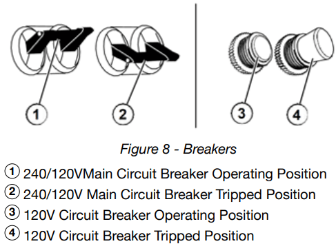
3. Make sure the circuit breakers are properly set (see Figure 8).
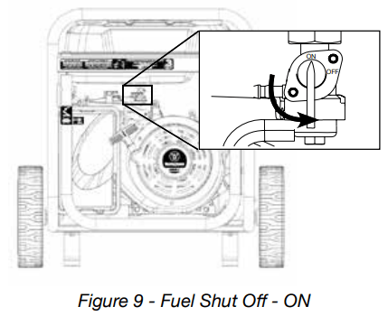
4. Move the fuel shutoff valve to the ON position (see Figure 9).
5. Push the engine control switch into the RUN position (see Figure 10).
6. Push and hold the push button start until the generator starts, then release. If using remote start then hold down START on the remote key fob until the generator starts, then release (see Figure 11).
The engine will automatically set the choke and begin the start sequence.
If the engine has started successfully the light indicator on the engine start button will turn green.
If the engine fails to start, the generator controls will attempt to start the engine two more times for a total of three attempts.
If the third attempt fails, the light on the engine start button will turn red.
If the engine has failed to start after three attempts the push button start can be pushed again to begin the automatic start sequence.
The engine control switch can be switched at any time during the automatic start sequence to abort the engine start attempt.
NOTE: If the cranking speed drops after each unsuccessful attempt, then the battery may not be adequately charged. You can alternatively start the generator using the recoil start as instructed in Manually Starting a Generator on page 21.
7. Plug in electric devices.
MANUALLY STARTING THE GENERATOR
Be sure to check oil levels before starting. If it is the first time starting make sure to add oil (see Adding Engine Oil page 24).
1. Make sure nothing is plugged into power outlets
2. Make sure the circuit breakers are properly set (see Figure 8).
4. Move the fuel shut off valve to the ON position (see Figure 9).
5. Push the engine control switch into the RUN position (see Figure 10).
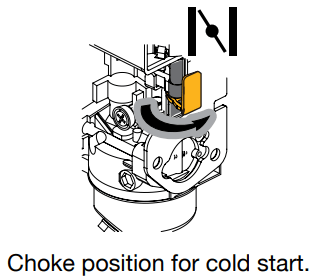
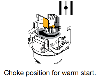
6. Manually set the choke:
a. Cold Start: Close the choke by moving it right towards the front handle of the generator.
b. Warm Start: Open the choke by moving it left towards the wheels of the generator.
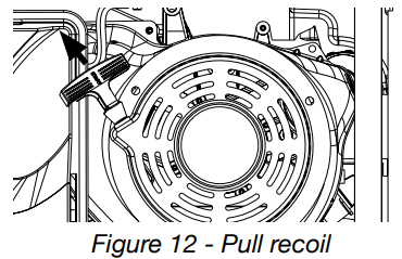
7. Firmly grasp and pull the recoil handle slowly until you feel increased resistance. At this point, apply a rapid pull while pulling up and slightly away from the generator (see Figure 12).
8. Plug in electric devices.
STOPPING THE GENERATOR
Normal Operation
During normal operation, use the following steps to stop your generator:
1. Remove any connected loads from the control panel receptacles.
2. Allow the generator to run at “no load” to reduce and stabilize engine and alternator temperatures.
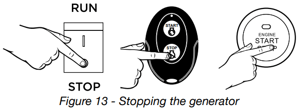
3. Choose from options below to stop the generator (see Figure 13):
Position the engine control switch to STOP
Hold push button start until generator stops
Hold the STOP button on the remote start key fob (Note: The generator will run for an additional 15 seconds as it goes through a cool down cycle before shutting off.)
NOTE If you plan to store the generator after use, stop the generator by turning the fuel shutoff valve to the OFF position and allow the fuel to be consumed from the carburetor.
4. Turn the fuel shutoff valve to the OFF position.
During anEmergency
If there is an emergency and the generator must be stopped quickly, position the engine control switch to the STOP position immediately
MAINTENANCE
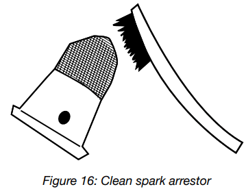
CLEANING THE SPARK ARRESTOR
Check and clean the spark arrestor after every 100 hours of use or 6 months.
1. Generator must be cold to perform this maintenance.
2. Move the inverter to a flat, level surface.
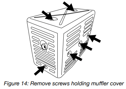
3. Remove the 6 screws holding the muffler cover in place (see Figure 14).
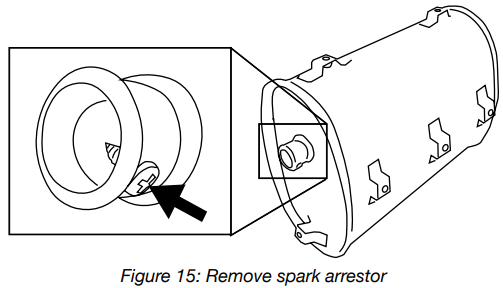
4. Once the cover is removed, locate the screw on the tip of the muffler and remove. Pull the spark arrestor out of the muffler. (see Figure 15).
5. If the spark arrestor screen shows signs of wear (rips, tears or large openings in the screen), replace the spark arrestor screen. NOTE: Only use Westinghouse spark arrestors as replacements.
6. If screen is not torn then clean using a wire brush, commercial solvent, or compressed air. Remove any dirt and debris that may have collected on the spark arrestor screen (see Figure 16).
7. Install the spark arrestor back into the muffler. Make sure to fully push it in so that it is tight on the tip of the muffler.
8. Replace the muffler cover and tighten all 6 screws.
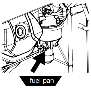
DRAINING CARBURETOR FLOAT BOWL
1. Make sure the generator is off and you are away from any open flames.
2. Place pan (or suitable container) under the carburetor assembly.
3. Loosen screw at bottom of the bowl and allow gas to drain out.
4. After all the gas has drained out, tighten the screw.
ENGINE OIL MAINTENANCE
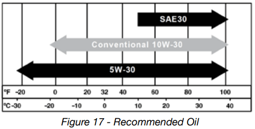
Engine Oil Specification
1. Only use the engine oil specified in Figure 17.
2. Only use 4-stroke/cycle engine oil. NEVER USE 2-STROKE/CYCLE OIL. Synthetic oil is an acceptable substitute for conventional oil.
CHECKING ENGINE OIL
Engine oil level should be checked before every use.
1. Always operate or maintain the generator on a flat surface.
2. Stop engine if running.
3. Let engine sit and cool for several minutes (allow crankcase pressure to equalize).
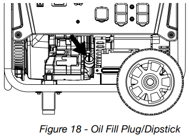
4. With a damp rag, clean around the oil fill plug/dipstick.
5. Remove oil fill plug/dipstick (see Figure 18 below).
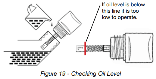
6. Check oil level: When checking the engine oil, remove the oil fill plug/dipstick and wipe it clean. Thread the oil fill plug/dipstick all the way back in and then remove and check the oil level on the oil fill plug/ dipstick.
• Acceptable Oil Level – Oil is visible on the crosshatches between the H and L lines on the oil fill plug/dipstick (see Figure 19).
• Low Oil – Oil is below the L line on the oil fill plug/ dipstick.
ADDING ENGINE OIL
Always operate or maintain the generator on a flat surface.
Stop engine if running.
Let engine sit and cool for several minutes (allow crankcase pressure to equalize).
Thoroughly clean around the oil fill plug/dipstick.
Remove oil fill plug/dipstick and wipe clean.
Select the proper engine oil as specified in Figure 17.
Using the supplied funnel, slowly add engine oil to the engine. Stop frequently to check the level to avoid overfilling.
Continue to add oil until the oil is at the correct level. See Figure 19.
Replace the oil fill plug/dipstick.
CHANGING ENGINE OIL
Always operate or maintain the generator on a flat surface.
Stop the engine.
Let engine sit and cool for several minutes (allow crankcase pressure to equalize).
Place oil pan (or suitable container) under the oil drain plug (see Figure 20).
With a damp rag, thoroughly clean around the oil drain plug.
Remove the oil drain plug (see Figure 20). Once removed, place the oil drain plug on a clean surface.
7. Allow oil to completely drain.
8. Replace oil drain plug.
9. Fill crankcase with oil following the steps outlined in Adding Engine Oil on page 24.
NOTICE Never dispose of used engine oil by dumping the oil into a sewer, on the ground, or into ground water or waterways. Always be environmentally responsible. Follow the guidelines of the EPA or other governmental agencies for proper disposal of hazardous materials. Consult local authorities or reclamation facility.
AIR FILTER MAINTENANCE
Cleaning the Air Filter
The air filter must be cleaned after every 50 hours of use or 3 months (frequency should be increased if generator is operated in a dusty environment).
Turn off the generator and let it cool for several minutes if running.
Move the generator to a flat, level surface.
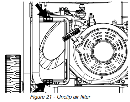
Unclip the clips on the top and bottom of the air filter cover (Figure 21).
4. Remove the black coarse air filters.
5. Wash the foam air filter elements by submerging the elements in a solution of household detergent soap and warm water. Slowly squeeze the foam to thoroughly clean.
6. Rinse in clean water by submerging the air filter elements in fresh water and applying a slow squeezing action.
7. Dispose of used soap cleaning solution properly.
8. Dry the air filter elements by again applying a slow firm squeezing action.
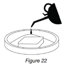
9. Once the air filters are dry, coat the air filters with clean engine oil (see Figure 22).
10. Squeeze the filters to remove any excess oil.
11. Install the filters back into the unit. Make sure the gray (fine) air filter goes in first followed by the black (coarse) air filter on the outside.
12. Install the air filter cover and secure the air filter assembly
SPARK PLUG MAINTENANCE
The spark plug must be checked and cleaned after every 100 hours of use or 6 months and must be replaced after 300 hours of use or every year.
1. Stop the generator and let it cool for several minutes if running.
2. Move the generator to a flat, level surface.
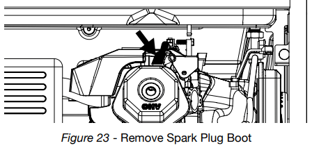
3. Remove the spark plug boot by firmly pulling the plastic spark plug boot handle directly away from the engine (see Figure 23).
NOTICE Never apply any side load or move the spark plug laterally when removing the spark plug. Applying a side load or moving the spark plug laterally may crack and damage the spark plug boot.
4. Clean area around the spark plug.
5. Using the 13/16” spark plug socket wrench provided, remove the spark plug from the cylinder head.
6. Place a clean rag over the opening created by the removal of the spark plug to make sure no dirt can get into the combustion chamber.
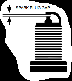
Inspect the spark plug for:
• Cracked or chipped insulator
• Excessive wear
• Spark plug gap (the acceptable limit of 0.027–0.032 in. [0.70 – 0.80 mm]).
NOTICE Use only recommended spark plugs when servicing. The manufacturer is not responsible for engine damage when using spark plugs not recommended by the manufacturer.
7. Install the spark plug by carefully following the steps outlined below:
a. Carefully insert the spark plug back into the cylinder head. Hand-thread the spark plug until it bottoms out.
b. Using the 13/16” spark plug socket wrench provided, turn the spark plug to ensure it is fully seated.
c. Replace the spark plug boot, making sure the boot fully engages the spark plug’s tip.
CHECKING AND ADJUSTING VALVE LASH
1. Remove the rocker arm cover and carefully remove the gasket. If the gasket is torn or damaged, it must be replaced.
2. Remove the spark plug so the engine can be rotated more easily.
3. Rotate the engine to top dead center (TDC) of the compression stroke. Looking through the spark plug hole, the piston should be at the top.
4. Both the rocker arms should be loose at TDC on the compression stroke. If they are not, rotate the engine 360°.
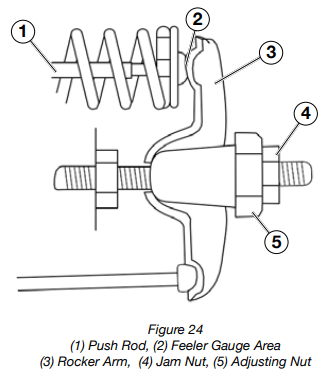
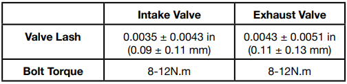
5. Insert a feeler gauge between the rocker arm and the push rod and check for clearance (see Figure 24). See Table 3 for valve lash specifications.
(Table 3) Standard Valve Lash
6. If an adjustment is required, hold the adjusting nut and loosen the jam nut.
7. Turn the adjusting nut to obtain the correct valve lash. When the valve lash is correct, hold the adjusting nut and tighten the jam nut to 106 in-lb (12 N•m).
8. Recheck the valve lash after tightening the jam nut.
9. Perform this procedure for both the intake and exhaust valves.
10. Install the rocker arm cover, gasket and spark plug.
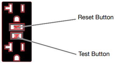
TESTING GFCI OUTLETS
1. Start the generator and allow it to warm up.
2. Press the test button on the GFCI outlet.
3. The reset button should pop out and there will be no power from the outlets. If the reset button does not pop out, the GFCI outlet is not working correctly and must be repaired before the generator can be operated.
4. Press the reset button to restore power to the outlet.
BATTERY SERVICE
To ensure the battery remains charged, the generator should be started every 2 to 3 months and run for a minimum of 15 minutes or a charger should be plugged into the generator and the generator should be charged overnight. Make sure the engine control switch is in the STOP position when charging. Plug the cord from the charger into the charging port on the generator control panel. Plug the charger into a 110/120-volt AC outlet.
BATTERY REPLACEMENT
Remove the spark plug wire from spark plug.
Loosen and remove the bolt on the battery hold down plate and swing the plate out.
Tip the battery forward slightly to access battery cables.
Disconnect the black negative (-) battery cable from the battery first.
Disconnect the red positive (+) battery cable second and remove the battery.
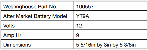
Install the new battery into the generator frame. Battery must meet specifications in table below to work properly.
Connect the red positive (+) battery cable to the battery first.
Connect the black negative (-) battery cable to the battery second.
Install the battery hold-down plate using the nuts removed in step 2.
Install the spark plug wire onto spark plug.
See below for the battery specification when replacing the battery.
CLEANING THE GENERATOR
It is important to inspect and clean the generator after every use.
Clean All Engine Air Inlet and Outlet Ports – Make sure all engine air inlet and outlet ports are clean of any dirt and debris to ensure the engine does not run hot.
Clean All Engine Cooling Fins – Use a damp rag and a brush to loosen and remove all dirt on or around the engine’s cooling fins.
Clean All Alternator Cooling Air Inlets and Exhaust Ports – Make sure the cooling air inlets and exhaust ports of the alternator are free of any debris and obstructions. Use a vacuum cleaner to remove dirt and debris stuck in the cooling air inlets and exhaust ports. General Cleaning of the Generator – Use a damp rag to clean all remaining surfaces.
STORING GENERATOR
Proper care should be taken to prepare the generator for any storage.
Make sure the Engine Switch is switched to STOP so the generator does not draw power from battery.
Clean the generator as outlined in Cleaning the Generator.
Drain all gasoline from the fuel tank as best as possible.
With the fuel shut off valve open, start the engine and allow the generator to run until all the remaining gasoline in the fuel lines and carburetor is consumed and the engine shuts off.
Close the fuel shut off valve.
Drain the remaining gas in the carburetor float bowl outlined in Draining Carburetor Float Bowl on page 23.
Change the oil (see Changing Engine Oil on page 25).
Remove the spark plug (see Spark Plug Maintenance on page 26) and place about 1 tablespoon of oil in the spark plug opening. While placing a clean rag over the spark plug opening, slowly pull there coil handle to allow the engine to turn over several times. This will distribute the oil and protect the cylinder wall from corroding during storage.
Replace the spark plug (see Spark Plug Maintenance on page 26).
Move the generator to a clean, dry place for storage.
TROUBLESHOOTING
WARNING Before attempting to service or troubleshoot the generator, the owner or service technician must first read the owner’s manual and understand and follow all safety instructions. Failure to follow all instructions may result in conditions that can lead to voiding of the EPA certification or product warranty, serious personal injury, property damage or even death.
PROBLEM
POTENTIAL CAUSE
SOLUTION
Engine is running, but no electrical output
1. Circuit breakers are tripped.
1. Reset the circuit breakers and check for overload condition.
2. The power cord’s plug connector is not fully engaged in the generator’s outlet.
2. Verify plug connector is firmly engaged in the generator’s outlet. If using the 240V outlet, make sure plug connector is rotated 1/4 turn in the clockwise direction.
3. Faulty or defective power cord
3. Replace power cord.
4. Faulty or defective electrical appliance
4. Try connecting a known good appliance to verify the generator is producing electrical power.
5. GFCI outlet is tripped
5. Press the reset button on the GFCI outlet.
6. If trying 1-5 above does not solve the problem, the cause might be the generator has a fault.
6. Take the generator to your nearest authorized service dealer.
Engine will not start or remain running while trying to start.
1. Fuel shutoff valve is in the OFF position.
1. Move the fuel shut off valve to the ON position.
2. Generator is out of gasoline.
2. Add gasoline to the generator.
3. Fuel flow is obstructed.
3. Inspect and clean fuel delivery passages.
4. Starting battery may have insufficient charge
4. On electric start models only. Check battery output and charge battery as necessary.
5. Dirty air filter
5. Check and clean the air filter.
6. Low oil level shut down switch is preventing the unit from starting.
6. Check oil level and add oil if necessary.
7. Spark plug boot is not fully engaged with the spark plug tip.
7. Firmly push down on the spark plug boot to ensure the boot is fully engaged.
8. Spark plug is faulty
8. Remove and check the spark plug. Replace if faulty.
9. Dirty/plugged spark arrestor
9. Check and clean the spark arrestor.
10. Stale fuel
10. Drain fuel and replace with fresh fuel.
11. If trying 1-11 above does not solve the problem, the cause might be the generator has a fault.
11. Take the generator to your nearest authorized service dealer.
Generator suddenly stops running.
1. Generator is out of fuel.
1. Check fuel level. Add fuel if necessary.
2. The low oil shut down switch has stopped the engine.
2. Check oil level and add oil if necessary.
3. Too much load.
3. Restart the generator and reduce the load.
4. If trying 1-3 above does not solve the problem,the cause might be a fault in the generator.
4. Take the generator to your nearest authorized service dealer.
Engine runs erratic; does not hold a steady RPM.
1. Dirty air filter
1. Clean the air filter.
2. Applied loads maybe cycling on and of
2. As applied loads cycle, changes in engine speed may occur; this is a normal condition.
3. If trying 1-3 above does not solve the problem, the cause might be a fault in the generator
3. Take the generator to your nearest authorized service dealer.
Q: Electric Starter not working. Battery @ 100% but no lights (yellow light dim and no green start button light) and no turning over at all. What are possible causes? Reply