Loading ...
Loading ...
Loading ...
1
Set the camera recorder to the Camera
mode.
(A P18 [Operation Modes] )
2
Set [Genlock Input] to “SDI”.
Set [A/V Set] B [Video Set] B [Genlock Input] to
“SDI”.
(A P126 [ Genlock Input A B ] )
Memo :
0
Set to “Adapter” to input synchronizing signal
from the accessory connection terminal (68
pins) on the rear of this unit.
3
When in the standby or stop mode, input
synchronizing signals from the SDI signal
generator to the [HD/SD SDI IN] terminal.
0
When the camera recorder’s video is locking
to the external synchronizing signal, “Sync
Locking” appears on the screen.
0
After locking to the external synchronizing
signal is complete, the display disappears
and recording can be performed.
0
If genlock is disconnected due to reasons
such as no signal input while genlock is in
operation, “Sync Unlocked” is displayed.
0
If there is genlock signal input but the signal
format is not supported, “Invalid Sync” is
displayed.
Memo :
0
If the frame rate of [WFrame & Bit Rate]/
[YFrame & Bit Rate] in the [Record Format]
menu is set to “60p”, “60i”, “30p”, or “24p”,
59.94 Hz synchronizing signals (vertical
synchronization) are input.
50 Hz/60 Hz synchronizing signals are not
synchronized.
0
If the frame rate of [WFrame & Bit Rate]/
[YFrame & Bit Rate] in the [Record Format]
menu is set to “50p”, “50i”, or “25p”, 50 Hz
synchronizing signals (vertical synchronization)
are input.
59.94 Hz/60 Hz synchronizing signals are not
synchronized.
(A P133 [ W Frame & Bit Rate ] )
(A P134 [ Y Frame & Bit Rate ] )
0
Do not connect or disconnect the input cable for
the synchronizing signals during recording or
playback
0
If the power is turned on during input of external
synchronizing signals, vertical oscillation may
occur. This is not a malfunction.
0
Signals such as VTR playback signals with
jitters may not be synchronized on this camera
recorder.
0
Only H (Horizontal) and V (Vertical) genlock
functions are available on this camera recorder.
It does not come with a lock function for SC (sub-
carrier). Color flash may occur during switching
such as when composite signals are used by a
switcher.
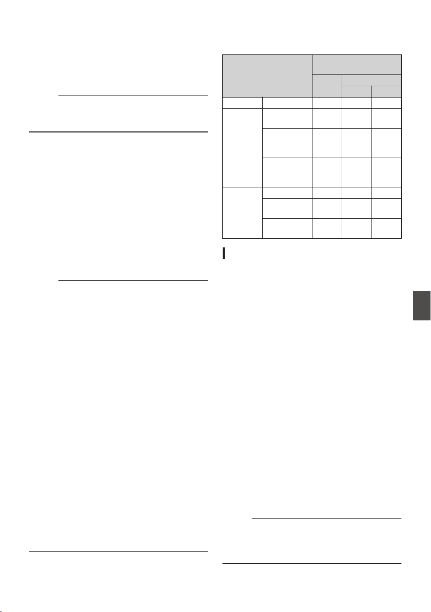
o Phase Items to Synchronize
The phase items to be synchronized may vary
depending on the input synchronizing signal and
output video signal.
Output Video Signal
Input Synchronizing
Signal
SD-
SDI
HD-SDI
720p 1080i
VIDEO Composite H, V, F V V, F
Y/PB/PR
A
B
SD
Component
H, V, F V V, F
HD
Component
720p
V H, V V
HD
Component
1080i
V, F V H, V, F
HD/SD
SDI
SD-SDI H, V, F V V, F
HD-SDI
720p
V H, V V
HD-SDI
1080i
V, F V H, V, F
Adjusting H Phase
1
Select [Genlock Adjust] in the [A/V Set]
menu.
Adjust the [A/V Set] B [Video Set] B Genlock
Adjust item as follows.
(A P126 [ Genlock Adjust ] )
[Analog SD H Phase] : Adjusts the H Phase
of the SD analog
signal.
[Analog HD H Phase]
A B
: Adjusts the H Phase
of the HD analog
signal.
[SD-SDI H Phase] : Adjusts the H Phase
of the SD SDI signal.
[HD-SDI H Phase] : Adjusts the H Phase
of the HD SDI signal.
2
Select a value using the cross-shaped
buttons (
JK).
0
The H Phase of the camera recorder’s video
signal is adjusted with respect to the external
synchronizing signal input from the
[GENLOCK] terminal.
0
The setting value of the [Analog HD H
Phase] A B, [SD-SDI H Phase], and
[HD-SDI H Phase] items can be adjusted in
increments of 10 by pressing the cross-
shaped button (JK) for 2 seconds or longer.
Memo :
0
Adjustment cannot be made while recording or
playback is in progress.
0
The video image may be disrupted momentarily
during adjustment. This is not a malfunction.
Inputting External Synchronizing Signals (Genlock)
171
Connecting External Devices
Loading ...
Loading ...
Loading ...