.
HD MEMORY CARD CAMERA RECORDER
GY-HM890U/GY-HM890E
GY-HM890CHU/GY-HM890CHE
GY-HM850U/GY-HM850E
GY-HM850CHU/GY-HM850CHE
INSTRUCTIONS
.
In this illustration, the supplied viewfinder, microphone, and lens are attached to the
GY-HM890U/GY-HM890E.
The lens is not supplied for GY-HM890CHU/GY-HM890CHE and GY-HM850CHU/GY-HM850CHE.
The specifications and appearance of this product are subject to changes for further improvement
without prior notice.
Please check the latest version of the INSTRUCTIONS from the following Mobile User Guide, or
download the PDF from the URL below.
Mobile User Guide
When you are outside, you can refer to the instructions from your Android phone or iPhone.
http://manual3.jvckenwood.com/pro/mobile/global/
You can view the Mobile User Guide using the browser on your Android phone or iPhone.
Ver. 1.00
LST1584-001A
Thank you for purchasing this JVC product.
Before operating this unit, please read the
instructions carefully to ensure the best
possible performance.
In this manual, each model number is
described without the last letter (U/E) which
means the shipping destination.
(U: for USA and Canada, E: for Europe)
Only “U” models (GY-HM890U/GY-HM890CHU/
GY-HM850U/GY-HM850CHU) have been
evaluated by UL.
Please read the following before getting started:
For Customer Use:
Model No.
Serial No.
Enter below the Serial No. which is located
on the body.
Retain this information for future reference.
GY-HM890U / GY-HM890CHU
GY-HM850U / GY-HM850CHU

2

Safety Precautions
.
1.
2.
IMPORTANT SAFEGUARDS
4.
Unplug this appliance system from the
wall outlet before cleaning. Do not use
liquid cleaners or aerosol cleaners.
Use a damp cloth for cleaning.
5.
Do not use attachments not
recommended by the appliance
manufacturer as they may cause
hazards.
6.
Do not use this appliance near water -
for example, near a bathtub,
washbowl, kitchen sink, or laundry tub,
in a wet basement, or near a swimming
pool, etc.
Read all of these instructions.
Save these instructions for later use.
7.
3.
All warnings on the product and in the
operating instructions should be
adhered to.
Do not place this
appliance on an
unstable cart, stand,
or table. The
appliance may fall,
causing serious injury
to a child or adult, and serious
damage to the appliance. Use only
with a cart or stand recommended by
the manufacturer, or sold with the
appliance. Wall or shelf mounting
should follow the manufacturer’s
instructions, and should use a
mounting kit approved by the
manufacturer. An appliance and cart
combination should be moved with
care. Quick stops, excessive force,
and uneven surfaces may cause the
appliance and cart combination to
overturn.
.
8.
Slots and openings in the cabinet and
the back or bottom are provided for
ventilation, and to insure reliable
operation of the appliance and to
protect it from overheating, these
openings must not be blocked or
covered. The openings should never
be blocked by placing the appliance
on a bed, sofa, rug, or other similar
surface. This appliance should never
be placed near or over a radiator or
heat register. This appliance should
not be placed in a built-in installation
such as a bookcase unless proper
ventilation is provided.
9.
This appliance should be operated
only from the type of power source
indicated on the marking label. If you
are not sure of the type of power
supplied to your home, consult your
dealer or local power company. For
appliance designed to operate from
battery power, refer to the operating
instructions.
10.
For added protection for this product
during a lightning storm, or when it is
left unattended and unused for long
periods of time, unplug it from the wall
outlet and disconnect the antenna or
cable system. This will prevent
damage to the product due to lightning
and power-line surges.
11.
Do not allow anything to rest on the
power cord. Do not locate this
appliance where the cord will be
abused by persons walking on it.
12.
Follow all warnings and instructions
marked on the appliance.
13.
Do not overload wall outlets and
extension cords as this can result in
fire or electric shock.
14.
Never push objects of any kind into
this appliance through cabinet slots as
they may touch dangerous voltage
points or short out parts that could
result in a fire or electric shock. Never
spill liquid of any kind on the appliance.
Safety Precautions
3
Introduction
.
15.
Do not attempt to service this
appliance yourself as opening or
removing covers may expose you to
dangerous voltage or other hazards.
Refer all servicing to qualified service
personnel.
16.
a.
b.
c.
d.
e.
f.
Unplug this appliance from the wall
outlet and refer servicing to qualified
service personnel under the following
conditions:
17.
When replacement parts are required,
be sure the service technician has
used replacement parts specified by
the manufacturer that have the same
characteristics as the original part.
Unauthorized substitutions may result
in fire, electric shock or other hazards.
18.
Upon completion of any service or
repairs to this appliance, ask the
service technician to perform routine
safety checks to determine that the
appliance is in safe operating
condition.
When the power cord or plug is
damaged or frayed.
If liquid has been spilled into the
appliance.
If the appliance has been exposed
to rain or water.
If the appliance does not operate
normally by following the operating
instructions. Adjust only those
controls that are covered by the
operating instructions as improper
adjustment of other controls may
result in damage and will often
require extensive work by a qualified
technician to restore the
appliance to normal operation.
If the appliance has been dropped
or the cabinet has been damaged.
When the appliance exhibits a
distinct change in performance -
this indicates a need for service.
.
The lightning flash with
arrowhead symbol, within an
equilateral triangle is
intended to alert the user to
the presence of uninsulated
“dangerous voltage” within
the product’s enclosure that
may be of sufficient
magnitude to constitute a
risk of electric shock to
persons.
The exclamation point within
an equilateral triangle is
intended to alert the user to
the presence of important
operating and maintenance
(servicing) instructions in the
literature accompanying the
appliance.
CAUTION
FOR USA AND CANADA
CAUTION:
TO REDUCE THE RISK OF
ELECTRIC SHOCK.
DO NOT REMOVE COVER (OR
BACK).
NO USER-SERVICEABLE PARTS
INSIDE. REFER SERVICING TO
QUALIFIED SERVICE PERSONNEL.
RISK OF ELECTRIC
SHOCK
DO NOT OPEN
CAUTION:
CHANGES OR MODIFICATIONS NOT
APPROVED BY JVC COULD VOID
USER’S AUTHORITY TO OPERATE
THE EQUIPMENT.
4
Safety Precautions
Introduction
.
Information for USA
This device complies with part 15 of the
FCC Rules. Changes or modifications
not approved by JVC KENWOOD could
void the user's authority to operate the
equipment.
This equipment has been tested and
found to comply with the limits for a
Class A digital device, pursuant to Part
15 of the FCC Rules. These limits are
designed to provide reasonable
protection against harmful interference
when the equipment is operated in a
commercial environment. This
equipment generates, uses, and can
radiate radio frequency energy and, if
not installed and used in accordance
with the instruction manual, may cause
harmful interference to radio
communications. Operation of this
equipment in a residential area is likely
to cause harmful interference in which
case the user will be required to correct
the interference at his own expense.
This device complies with Part 15 of the
FCC Rules.
Operation is subject to the following two
conditions: (1)This device may not
cause harmful interference, and (2) this
device must accept any interference
received, including interference that
may cause undesired operation.
Due to design modifications, data given
in this instruction book are subject to
possible change without prior notice.
.
POUR CANADA
RISQUE
D’ELECTROCUTION
NE PAS OUVRIR
ATTENTION:
POUR EVITER TOUT RISQUE
D’ELECTROCUTION NE PAS
OUVRIR LE BOITER. AUCUNE
PIECE INTERIEURE N’EST A
REGLER PAR L’UTILISATEUR. SE
REFERER A UN AGENT QUALIFIE
EN CAS DE PROBLEME.
ATTENTION
Le symbole de l’éclair à
l’intérieur d’un triangle
équilatéral est destiné à
alerter l’utilisateur sur la
présence d’une “tension
dangereuse” non isolée dans
le boîtier du produit. Cette
tension est suffisante pour
provoquer l’électrocution de
personnes.
Le point d’exclamation à
l’intérieur d’un triangle
équilatéral est destiné à
alerter l’utilisateur sur la
présence d’opérations
d’entretien importantes au
sujet desquelles des
renseignements se trouvent
dans le manuel
d’instructions.
Ces symboles ne sont
utilisés qu’aux Etats-Unis.
CAN ICES-3 A / NMB-3 A
The apparatus shall not be exposed to
dripping or splashing and that no objects
filled with liquids, such as vases, shall be
placed on the apparatus.
Safety Precautions
5
Introduction

.
WARNING:
TO PREVENT FIRE OR SHOCK
HAZARD, DO NOT EXPOSE THIS
UNIT TO RAIN OR MOISTURE.
CAUTION:
This unit should be used with 12V DC only.
To prevent electric shocks and fire hazards,
do NOT use anyother power source.
AVERTISSEMENT :
POUR EVITER LES RISQUES
D’INCENDIE OU D’ELECTROCUTION,
NE PAS EXPOSER L’APPAREIL A LA
PLUIE NI A L’HUMIDITE.
ATTENTION:
Ce magnétoscope ne doit être utilisé que
sur du courant direct en 12V.
Afin d’eviter tout resque d’incendie ou
d’electrocution, ne pas utillser d’autres
sources d’alimentation électrique.
NOTE:
The rating plate and safety caution are
on the bottom and/or the back of the
main unit.
REMARQUE :
La plaque d’identification et
l’avertissement de sécurité se trouvent
sous l’appareil et/ou au dos.
WARNING
This is a Class A product. In a domestic
environment this product may cause radio
interference in which case the user may
be required to take adequate measures.
CAUTION:
To prevent electric shock, do not open
the cabinet.
No user serviceable parts inside. Refer
servicing to qualified service personnel.
FOR EUROPEAN
The plastics packaging bags may cause
suffocation when they are covered over the
head. Tear them open, and keep them away
from the reach of infants and children by
ensuring that they are disposed of properly.
.
Dear Customer
This apparatus is in conformance with
the valid European directives and
standards regarding electromagnetic
compatibility and electrical safety.
European representative of
JVC KENWOOD Corporation is:
JVC Technical Services Europe GmbH
Konrad-Adenauer-Allee 1-11
61118 Bad Vilbel
Germany
Sehr geehrter Kunde, sehr geehrte
Kundin, dieses Gerät stimmt mit den
gültigen europäischen Richtlinien und
Normen bezüglich elektromagnetischer
Verträglichkeit und elektrischer
Sicherheit überein.
Die europäische Vertretung für die
JVC KENWOOD Corporation ist:
JVC Technical Services Europe GmbH
Konrad-Adenauer-Allee 1-11
61118 Bad Vilbel
Deutschland
.
Manufacturer
3-12,Moriya-cyo,Kanagawa-ku,
Yokohama-shi,
Kanagawa 221-0022,Japan
Importer (EU only)
JVC House
JVC Business Park
12 Priestley Way,London NW2 7BA,
United Kingdom
6
Safety Precautions
Introduction
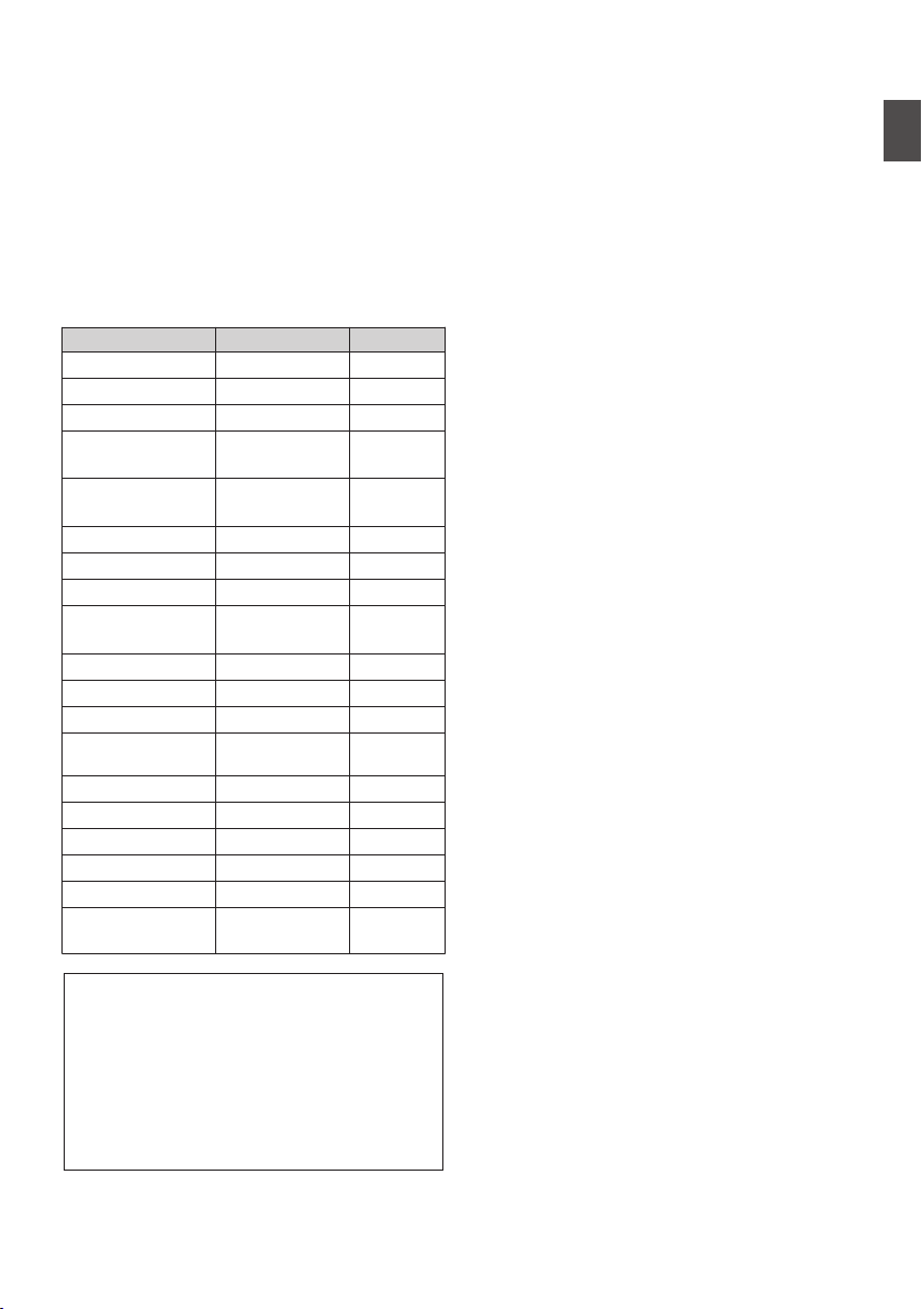
FOR EUROPE
0
This equipment is in conformity with the
provisions and protection requirements of the
corresponding European Directives. This
equipment is designed for professional video
appliances and can be used in the following
environments:
Controlled EMC environment (for example,
purpose-built broad-casting or recording studio),
and rural outdoors environments.
In order to keep the best performance and
furthermore for electromagnetic compatibility we
recommend to use cables not exceeding the
following lengths:
Terminal Cable Length
[DC INPUT] Exclusive Cable 5 m
[VIDEO OUT] Coaxial Cable 10 m
[INPUT1/INPUT2] Shielded Cable 3 m
[AUDIO OUTPUT
CH-1/3]
Shielded Cable 10 m
[AUDIO OUTPUT
CH-2/4]
Shielded Cable 10 m
[AUX] Shielded Cable 5 m
[PHONES] Exclusive Cable 3 m
[HDMI] Shielded Cable 3 m
[HD/SD SDI
IN] A B
Coaxial Cable 10 m
[HD/SD SDI OUT] Coaxial Cable 10 m
[REMOTE1] Exclusive Cable 5 m
[REMOTE2] Exclusive Cable 1 m
[LENS] Unshielded
Cable
0.1 m
[VF] Special cable 0.3 m
[DEVICE] Shielded Cable 2 m
[GENLOCK] Coaxial Cable 10 m
[TC IN] Coaxial Cable 10 m
[TC OUT] Coaxial Cable 10 m
[STUDIO] A
B
Exclusive Cable 0.3 m
.
Caution:
Where there are strong electromagnetic
waves or magnetism, for example near a
radio or TV transmitter, transformer,
motor, etc., the picture and the sound
may be disturbed. In such case, please
keep the apparatus away from the
sources of the disturbance.
.
Para Brasil
Informação sobre eliminação de
baterias
Este produto não deverá ser eliminado
como lixo doméstico em geral.
Devolva a bateria velha ao comerciante
ou para a rede autorizada, para que seja
devolvida ao fabricante ou importador.
A reciclagem e eliminação de lixo em
uma maneira adequada, ajudarão para
preservar recursos, prevenindo, ao
mesmo tempo, contra efeitos prejudiciais
sobre a nossa saúde e o meio ambiente.
o
Safety Precautions
7
Introduction
.
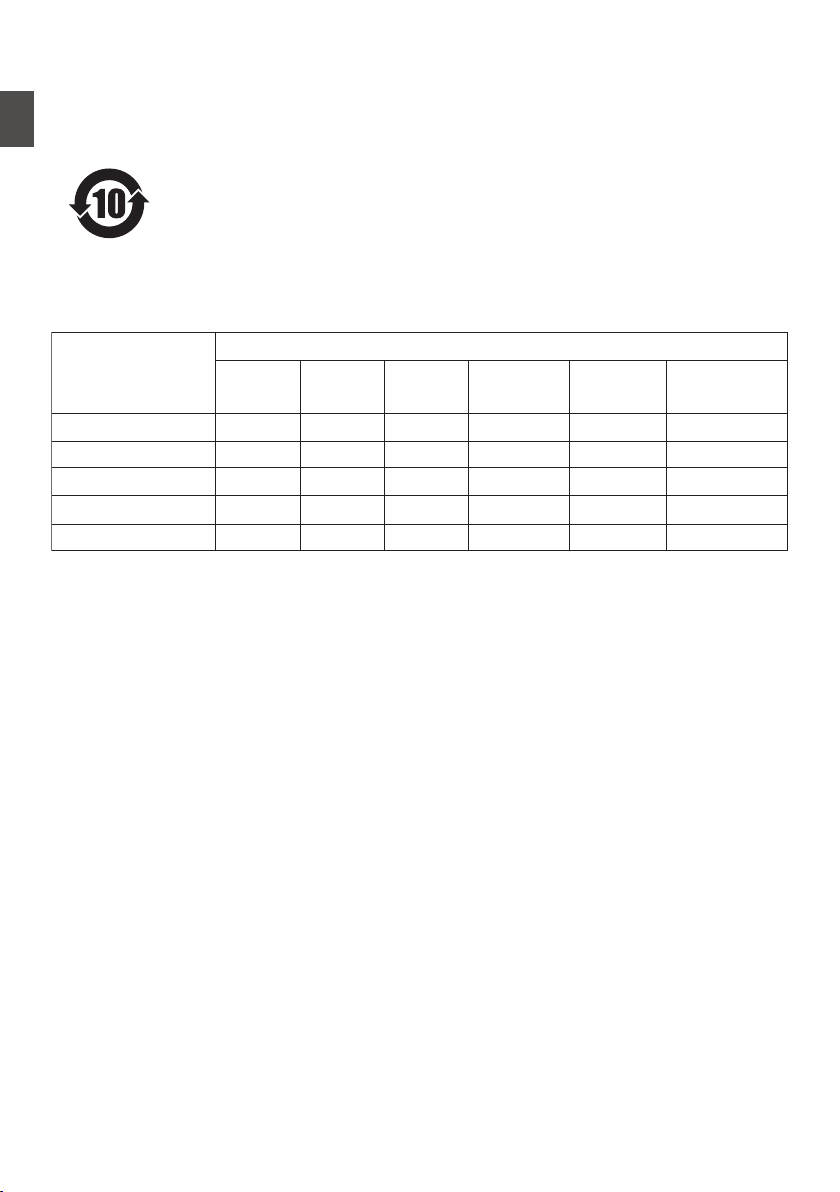
ḏ䌰ἀ䒩㚠旑
ḏḨ⑂ᶮ䘅㚊㭓ɜ㚊⬴䇪岩
晷ṷ⎎䥱
㚊㭓㚊⬴䇪岩㆗䲡
摆
澐Qc澑
㯟
澐Ih澑
擊
澐De澑
Ṹ摭
澐Ds)WJ*澑
⢛㸵俕剰
)QCC*
⢛㸵ḍ剰愛
澐QCEF澑
乀嵰㜀久ṷȵȵȵȵ
㚻䬲ȵȵȵȵ
⫧䱼习
㴳㗷㖿䢻⯐㦢⛘
ṗ旅ṷ
ȵȵȵȵ
ȵȵȵȵ
ȵȵȵȵ
䌰ἀ䒩㚠旑
㫥♿㞈埩䢻ḇᶮ♾ɤ䒶⫑ὢ⿰Ḩ⑂㯢㝔㌨↷䬢䎇∟㱖ɥ奅⬛䘅䌰
ἀ䒩㚠旑ɝ⍫夂䒩ㆸ⚩ἀ䒩㚭Ḩ⑂㕷忶⬉㱩ゐḌ柺ᶮ䘅⎅柺奅
⬛澔ṏ↷御㕦㚠⺁⥌↱㫥♿㞈㞈ⅻ䘅㚠旑ᶻ㫣澐䌰ἀ䒩㚠旑澑
㕣ᶎẛ㯢㝔䌰⠄ᶎẛḨ䒠⭺ḻỔ㚊⬴䘅䇪岩ɝ
ȵ澢
澢!
埩䢻学㚊㭓㚊⬴䇪岩⚩学恩ṷ㇁㚊⛈岩㛑㔚ᶮ䘅⎬慐⛈⚩!HC0U37683.3122!
奅⬛䘅旑慐夂㯃Ṧᶌɝ
埩䢻学㚊㭓㚊⬴䇪岩兴⮒⚩学恩ṷ䘅㝑ᶁ⛈岩㛑㔚ᶮ䘅⎬慐崆ⅻ!
HC0U37683.3122!奅⬛䘅旑慐夂㯃ɝ
ɤ䒶⫑ὢ⿰Ḩ⑂㯢㝔㌨↷䬢䎇∟㱖ɥ奅⬛䘅埩䢻℆⬺
8
Safety Precautions
Introduction

Contents
Introduction
Safety Precautions ............................................ 3
Contents ............................................................ 9
Main Features ................................................. 12
Precautions for Proper Use ............................. 14
Operation Modes ............................................. 18
Names of Parts ................................................ 20
Side Control Panel ....................................... 22
Viewfinder .................................................... 23
LCD Monitor ................................................ 24
Side Terminal Section .................................. 24
SD Slot ......................................................... 25
Rear Terminal .............................................. 25
Lens Section A C ................................ 26
Basic System Diagram .................................... 27
Preparations
Settings and Adjustments Before Use ............. 28
Attaching the Lens (Supplied) ...................... 28
Adjusting the Grip Belt A C ................. 28
Attaching the Microphone (Supplied) ........... 28
Attaching the Viewfinder (Supplied) ............. 28
Opening/Closing the Lens Cover A C . 29
Attaching/Detaching the Hood A C ..... 29
Attaching the Anti-reflective Film .................. 30
Power Supply .................................................. 30
Using AC Power (DC IN Power) ................... 30
Using a Battery Pack .................................... 31
Power Status Display ...................................... 32
Turning On/Off the Power ................................ 33
Initial Settings .................................................. 34
Displays on the LCD Monitor and Viewfinder .. 36
Display Screen ............................................. 36
Status Screen .............................................. 37
USB Mode Screen ....................................... 38
Remote Edit Mode Screen ........................... 38
Warning Display ........................................... 38
Adjusting the LCD Monitor and Viewfinder ...... 38
Adjusting the LCD Monitor ........................... 39
Adjusting the Viewfinder .............................. 40
Adjusting the Monitor Speaker ........................ 40
Adjusting Back Focus ...................................... 41
Assignment of Functions to User Buttons ........ 42
Tally Lamp ....................................................... 42
SD Card ........................................................... 43
Usable Cards ............................................... 43
Formatting (Initializing) SD Cards ................ 45
Restoring and Updating the SD Card ........... 46
Clips Recorded to SD Cards ........................ 47
About the Operation Lock Feature ................... 48
Shooting
Basic Shooting Procedures ............................. 49
Selecting a Recording Format ......................... 50
Zoom Operation .............................................. 52
Focus Operation F .................................... 53
Adjusting the Focus by Face Detection F . 56
Adjusting the Brightness .................................. 57
Adjusting the Iris .............................................. 58
Setting the Gain ............................................... 59
Setting the Electronic Shutter .......................... 60
Setting the ND Filter ........................................ 62
Adjusting the White Balance ............................ 63
Adjusting the Camera Image ........................... 68
Using the Image Stabilizer F ..................... 68
Audio Recording .............................................. 69
Audio Output during Recording ....................... 72
Time Code and User’s Bit ................................ 72
Setting Time Code Generator .......................... 73
Setting the User’s Bit ....................................... 76
Synchronizing the Time Code with an External
Time Code Generator ...................................... 78
Setting Zebra Pattern ...................................... 79
Setting Spot Meter ........................................... 80
Acquiring Positioning Information by GPS ....... 82
Viewing Recorded Videos Immediately (Clip
Review) ........................................................... 83
Using the Histogram ........................................ 84
Recording Simultaneously at Two Different
Definitions ....................................................... 84
Splitting the Clips Freely (Clip Cutter Trig) ....... 85
Dual Rec .......................................................... 85
Backup Rec ..................................................... 87
Special Recording ........................................... 89
Pre Rec ........................................................ 89
Clip Continuous Rec .................................... 89
Frame Rec ................................................... 91
Interval Rec .................................................. 92
Variable Frame Rec ..................................... 93
Playback
Playing Recorded Clips ................................... 94
Thumbnail Screen ........................................ 94
Actions ......................................................... 96
Playing back ................................................ 97
Deleting Clips .................................................. 98
Appending/Deleting OK Mark .......................... 99
Contents
9
Introduction

Selecting and Performing Operations on Multiple
Clips .............................................................. 100
Selecting Multiple Clips Randomly ............. 100
Selecting Multiple Clips Consecutively ...... 101
Trimming Recorded Clips .............................. 102
Menu Display and Detailed Settings
Basic Operations in Menu Screen ................. 103
Display and Description of the Menu Screen
................................................................... 104
Text Input with Software Keyboard ............ 105
About the Menu Lock Feature ....................... 106
Menu Screen Hierarchical Chart ................... 107
Camera Function Menu ................................. 108
User Switch Set Item .................................. 111
FULL AUTO Item ....................................... 113
Camera Process Menu .................................. 114
Detail/Adjust Item ....................................... 117
White Balance Item .................................... 118
TC/UB Menu ................................................. 119
LCD/VF Menu ................................................ 120
Shooting Assist Item .................................. 121
Marker Settings Item .................................. 121
Display Settings Item ................................. 122
A/V Set Menu ................................................ 125
Video Set Item ........................................... 125
Audio Set Item ........................................... 127
System Menu ................................................ 130
Record Set Item ......................................... 132
Network/Settings Item ................................ 137
Adding/Editing Frequently Used Menu Items 142
Registration to Favorites Menu .................. 142
Editing Favorites Menu .............................. 143
Display/Status Screen
Display Screen in Camera Mode ................... 145
Display Screen in Media Mode ...................... 151
Status Screen ................................................ 153
Camera Features
Marker and Safety Zone Displays .................. 154
Smoothening the Skin Color (Skin Detail
Function) ....................................................... 155
Color Bar Output ........................................... 155
Adjusting Color Matrix ................................... 156
Configuring Setup Files ................................. 157
Saving Setup Files ..................................... 157
Loading a Setup File .................................. 158
Deleting Setup Files ................................... 159
Connecting External Devices
Managing/Editing Clips on a PC .................... 160
Connecting External Monitor ......................... 161
Connecting a Earphone ................................. 163
Connecting Wired Remote Control ................ 164
Connecting a Remote Control Unit ................ 164
Functions Operable from the Remote Control Unit
....................................................................... 166
Inputting SDI Signals from an External Device A
B ............................................................ 168
Inputting External Synchronizing Signals
(Genlock) ....................................................... 169
Displaying Return Videos from an External Device
A B .................................................... 172
Studio System A B ............................ 172
Connecting to the Network
Functions of Network Connection .................. 174
Preparing Network Connection ...................... 174
Operating Environment .............................. 174
Camera Setup for Network Connection ..... 175
Connecting via Wireless LAN .................... 175
Connecting via Wired LAN ......................... 177
Connecting via Cellular Adapter ................ 177
Importing Metadata ....................................... 178
Preparing Metadata ................................... 178
Configuring the Server for Downloading .... 178
Importing Metadata .................................... 179
Uploading a Recorded Video Clip ................. 180
Configuring the FTP Server for Uploading . 180
Uploading Video Clip ................................. 180
Connecting from a Web Browser ................... 182
Editing Metadata ........................................... 183
Planning Metadata ..................................... 183
Clip Metadata ............................................ 184
Uploading a Recording Clip via a Web Browser
....................................................................... 187
View Remote Feature .................................... 190
Operating Procedure ................................. 190
Registering/Deleting Preset Zoom ............. 191
Camera Control Function .............................. 193
Changing the Settings via a Web Browser .... 194
Changing View Remote Function Settings . 195
Changing Connection Setup ...................... 196
Changing Metadata Server Settings .......... 197
Changing Clip Server Settings ................... 197
Changing Streaming Settings .................... 197
Managing the Network Connection Settings File
....................................................................... 197
Saving the Connection Settings File .......... 197
Reading the Connection Settings File ........ 198
Deleting Connection Settings .................... 199
Performing Live Streaming ............................ 199
10
Contents
Introduction

Setting Distribution ..................................... 200
Starting Distribution ................................... 200
Others
Error Messages and Actions ......................... 202
List of FTP Transfer Errors ......................... 203
List of Live Streaming Error Displays ......... 205
Blinking of the Tally Lamp .......................... 206
Warning Tone ............................................ 206
Troubleshooting ............................................ 206
Specifications ................................................ 209
Index ............................................................. 214
Software License Agreement ........................ 216
Important Notice concerning the Software ..... 217
Open Source License .................................... 218
.
Contents
11
Introduction

Main Features
Inheriting the compact shoulder-carry
style
Inheriting the compact shoulder-carry style of the
GY-HM700 series, this camera recorder enables
more stable shooting while maintaining the same
weight as handheld models.
F11 Sensitivity, 1/3-inch Full HD 3CMOS
Sensors
This camera recorder is equipped with three 1/3-
inch 2.07M pixels full HD CMOS sensors.
It delivers high image quality with a high color
resolution through the processing of individual R,
G, B color signals. 12-bit signal processing and the
new 2D DNR removes dark current and optical shot
noise without losing S/N and high resolution,
thereby achieving high F11 sensitivity.
Equipped with the newly-developed
Fujinon 20x interchangeable zoom lens
with AF/OIS
A C
It ensures high magnification of 29 mm at wide
ends, and provides high sensitivity across all
regions with F1.6-3.0.
This interchangeable lens comes with an
autofocus (AF) and Optical Image Stabilizer (OIS)
function, allowing for stable focusing when used as
a shoulder-carry camera recorder.
In addition to the central area, it also comes with a
face-detection autofocus feature, and supports
switching to manual focusing.
The zoom ring with zoom ring pin enables zooming
from the wide end to the tele end in 90 degrees.
Focus and iris control are also possible using
separate rings.
4-position ND Filter
This camera recorder incorporates three types of
ND filters.
Adjust the amount of light according to the
brightness during shooting by switching the 4-
position ND filter (OFF, 1/4, 1/16, 1/64).
JVC’s Proprietary FALCONBRID High-
Quality Imaging Engine
The FALCONBRID high-quality imaging engine
omits unnecessary processing through
incorporating camera processing and image
compression on a single chip. Images from
imaging devices are compressed and processed
without any loss thereby achieving high-quality
images.
MPEG2 and H.264 Codec
FALCONBRID allows users to select a recording
format such as MPEG-2, H.264 and AVCHD
Progressive, the most commonly used codec for
professional videos.
50 Mbps high-resolution recording
mode
This camera recorder comes with a 50 Mbps mode
in the H.264 format (1920x1080: MOV) to support
high-resolution video recording.
QuickTime (MPEG-2 HD/H.264 HD/
H.264 SD)/MP4 (MPEG-2 HD)/AVCHD
File Formats
Inheriting the concept of ProHD memory camera
recorders, this camera recorder also supports
various file formats, such as AVCHD and
QuickTime (H.264 SD) files, as well as QuickTime
(MPEG-2 HD/H.264 HD) files that can be directly
edited on Apple Final Cut Pro, in addition to MP4
files that are most suitable for XDCAM EX
Nonlinear Editing Workflow.
Two SDHC/SDXC Card Slots for Dual,
Backup and Series Recording
The most common SDHC/SDXC card recording
system is used as the memory card.
This ensures reliability and operation at low running
cost.
Various user friendly recording systems are also
available. These include dual recording of the
same file to two cards, and using REC/STBY to
break up video clips in one card while performing
backup recording to the other card.
Diverse simultaneous recording
combinations (HD and SD, HD and
Proxy Video, etc.)
This camera recorder is equipped with a proxy
video (960x540: MOV, 480x270: MOV,
1440x1080: AVCHD) recording function that is
convenient for network distribution.
Further enhancements were made to the dual
recording feature, allowing for HD recording to one
of the SDHC/SDXC cards, and SD or proxy video
recording to the other card at the same time.
12
Main Features
Introduction

Variable frame recording
Enables beautiful slow motion and quick motion
image recording such as overcrank and
undercrank.
Th ability to change the frame rate during recording
enables quick to gradually slow motion effects.
Pre Rec function (up to 10 seconds) and
Interval Rec function
SDI/HDMI Simultaneous Output
Equipped with both [HD/SD SDI] and [HDMI]
terminals as digital output.
Non-compressed full HD video signals and audio
signals can be output to the [HD/SD SDI] and
[HDMI] terminals at the same time.
Comes with genlock input and time
code input/output terminals
This camera recorder supports the use of multiple
cameras as well as studio use.
Professional Switch Layout and Various
Video Parameter Settings
Switches for Gain and White Balance are available
on the side panel to enable quick switching
according to the shooting scene.
Image parameters such as gamma and color
matrixes are also available in the menu for
adjusting preferred tones.
0.45-inch 1.22-megapixel color
viewfinder, 4.3-inch 1.15-megapixel
LCD display
(Equipped with Focus Assist function)
4-channel audio
Supports 4-channel audio in the MPEG-2/H.264
recording mode.
In addition to two mic inputs, you can also record
audio input from the [AUX] input terminal to an
independent track.
2-channel XLR audio input
(microphone/line switch, phantom
power supply) and mini jack input
terminal for wireless microphone
receiver
Supports two types of wired remote
control units
In addition to JVC’s original 6-pin remote terminal,
this camera recorder is also equipped with a
φ2.5mm stereo jack remote control terminal.
Built-in GPS
This camera recorder is built in with a GPS function,
which enables the positional information obtained
from the GPS satellite during a shoot to be
recorded as metadata.
* Note that acquisition of the positional information
may fail depending on the weather condition.
Diverse Network Functions
This camera recorder supports functions such as
remote control from a mobile device, viewing,
metadata transmission, and proxy file transfer as
an FTP client.
Equipped with a USB host function, you can upload
recorded files stored in this unit via a network by
connecting it to network devices such as a wireless
LAN adapter (optional). Video and audio streaming
is also supported.
Professional-spec battery
This camera recorder supports the use of batteries
used by broadcasting stations, such as Anton/
Bauer and IDX batteries.
(Gold Mount: For use with Anton/Bauer battery (U
model), V Mount: For use with IDX battery (E
model))
Application Software Provided
The [JVC ProHD Clip Manager] application
software is provided for you to copy recorded clips
to Windows or Macintosh computers and for
checking the video images. (For MP4 file format)
The disc provided with this camera recorder
comes with [JVC ProHD Clip Manager] and other
application software as well as their user guides.
* For details, refer to the user guides for each
application software.
Main Features
13
Introduction

Content of this manual
Symbols used
Caution : Describes precautions concerning the
operation of this product.
Memo : Describes reference information, such as
functions and usage restrictions of this
product.
A
: Indicates the reference page numbers and
reference items.
A
: Feature available on
GY-HM890U/GY-HM890E only.
B
: Feature available on
GY-HM890CHU/GY-HM890CHE only.
C
: Feature available on
GY-HM850U/GY-HM850E only.
D
: Feature available on
GY-HM850CHU/GY-HM850CHE only.
F
: Feature available only with the supplied
lens.
Content of this manual
0
All rights reserved by JVC KENWOOD Corporation.
Unauthorized duplication or reprinting of this
manual, in whole or in part, is strictly prohibited.
0
Illustrated designs, specifications and other
contents of this manual are subject to change for
improvement without prior notice.
0
AVCHD Progressive and the AVCHD Progressive
logo are trademarks of Panasonic Corporation and
Sony Corporation.
0
XDCAM EX is a trademark of Sony Corporation.
0
SDXC and SDHC logos are trademarks of SD-3C,
LLC.
0
HDMI (High-Definition Multimedia Interface) and
1
are trademarks of HDMI Licensing,
LLC.
0
QuickTime, Final Cut Pro, iPhone, iPad, iPod touch,
iOS, Mac OS and Safari are trademarks of Apple
Inc., registered in the U.S. and other countries.
0
Android and Google Chrome are trademarks
and/or registered trademarks of Google Inc.
0
QR Code is a registered trademark of Denso Wave
Incorporated.
0
Dolby and the double-D symbol are trademarks of
Dolby Laboratories.
0
Microsoft, Windows, Windows XP, Windows Vista,
Windows 7, Windows 8, and Internet Explorer are
registered trademarks of Microsoft Corporation in
the United States and/or other countries.
0
Mozilla and Firefox are either trademarks or
registered trademarks of Mozilla Foundation in the
United States and/or other countries.
0
Intel Core 2 Duo is a trademark or registered
trademark of Intel Corporation or its subsidiaries in
the United States and other countries.
0
The company name of Fontworks, Fontworks, and
the name of the fonts are registered trademarks of
Fontworks Inc.
0
Other product and company names included in this
instruction manual are trademarks and/or
registered trademarks of their respective
companies. Marks such as ™ and ® have been
omitted in this manual.
Precautions for Proper
Use
Storage and Usage Locations
o Allowable ambient temperature and humidity
Be sure to use this unit within the allowable
temperature range of 0 °C to 40 °C (32 °F to 104°F)
and a relative humidity of 35 % to 80 %. Using this
unit at a temperature or humidity outside the
allowable ranges could result not only in
malfunction but also serious impact on the CMOS
elements as small white spots may be generated.
Please exercise care during use.
o Strong electromagnetic waves or magnetism
Noise may appear in the picture or audio and/or the
colors may be incorrect if this unit is used near a
radio or television transmitting antenna, in places
where strong magnetic fields are generated by
transformers, motors, etc., or near devices emitting
radio waves, such as transceivers or cellular
phones.
o Use of wireless microphone near this unit
When a wireless microphone or wireless
microphone tuner is used near this unit during
recording, the tuner could pick up noise.
o Avoid using or placing this unit in the following
places.
0
Places subject to extreme heat or cold
0
Places with excessive dirt or dust
0
Places with high humidity or moisture
0
Places subject to smoke or vapor such as near
a cooking stove
0
Places subject to strong vibrations or unstable
surfaces
0
In a parked car under direct sunlight or near a
heater for long hours
o Do not place this unit at places that are subject
to radiation or X-rays, or where corrosive gases
occur.
o Protect this unit from being splashed with water.
(Especially when shooting in the rain)
o Protect this unit from getting wet when shooting
on a beach. In addition, salt and sand may adhere
to the body. Clean the unit after use.
o Protect this unit against penetration of dust when
using it in a place subject to sandy dust.
14
Content of this manual
Introduction

Transportation
Do not drop or hit this unit against a hard object
when transporting.
Power Saving
When this unit is not in use, be sure to set the
[POWER ON/OFF] switch to “OFF” in order to
reduce power consumption.
Maintenance
o Turn off the power before performing any
maintenance.
o Wipe the external cabinet of the unit with a soft
cloth. Do not wipe the body with benzene or thinner.
Doing so may cause the surface to melt or turn
cloudy. When it is extremely dirty, soak the cloth in
a solution of neutral detergent, wipe the body with
it, and then use a clean cloth to remove the
detergent.
Batteries
o The batteries recommended for use with this
camera recorder are as follows.
U model : Dionic90 (Anton/Bauer)
E model : Endura-HL9 (IDX)
o Please make use of one of the recommended
batteries.
Heavy batteries may fall off if they are not used
correctly.
Regular Inspection (Maintenance)
Under normal environment, dust will accumulate
on the camera recorder when it is used over a long
period. Dust may enter the camera recorder
especially if it is used outdoors. This may affect the
image and sound quality of the camera recorder.
Check and replace the fan after every 9000 hours
(suggested guideline).
You can check the usage time of the fan in [System]
B [System Information] B [Fan Hour].
(A P132 [ Fan Hour ] )
If the fan is used for more than 9000 hours without
replacement, “FAN MAINTENANCE REQUIRED”
will be displayed every time you turn on the power.
About GPS
o The GPS (Global Positioning System) satellites
are managed by the Department of State of the
U.S., and its precision may be altered intentionally.
o Perform positioning at an unobstructed location
with a clear view that is not indoors or blocked by
trees.
o The time needed for obtaining the position
information may be longer and variation may also
be larger depending on the surrounding
environment and time of day.
o This camera recorder uses the WGS 84 World
Geodetic System.
o Signal from GPS satellites may be interrupted by
communication signal from electronic devices
such as mobile phones.
LCD Monitor and Viewfinder
o The LCD monitor and viewfinder screen are
manufactured using high-precision technology.
Black spots may appear on the LCD monitor and
viewfinder screen, or red, blue, and/or white spots
may not disappear. However, this is not a
malfunction and these spots are not recorded on
the SD card.
o If you use this unit continuously for a long period
of time, the characters displayed in the viewfinder
may temporarily remain on the screen. This is not
recorded on the SD card. They will not appear after
you turn the power off and then on again.
o If you use this unit in a cold place, the images
may appear to lag on the screen, but this is not a
malfunction. Retained images are not recorded on
the SD card.
o Do not press against the surface with force or
subject it to strong impact. Doing so may damage
or break the screens.
o Noise may appear in the viewfinder when
switching between the live video and playback
images.
o Due to the characteristic of the viewfinder display
device, colors may appear on the images when you
blink your eyes. It does not affect the recorded
images, SDI output, or HDMI output.
Precautions for Proper Use
15
Introduction

SDHC/SDXC Cards
o SDHC/SDXC card is referred to as “SD card” in
this manual.
o This camera recorder saves the recorded
images and audio sound on the SD card (sold
separately) in the card slot.
o Use an SD card (4 GB to 128 GB) with Class 6
or higher performance, formatted using this
camera recorder.
* Depending on the recording format, SD card with
Class 4 or higher performance can also be used.
Some recording formats supports only the use of
cards with Class 10 or higher.
(A P50 [Selecting a Recording Format] )
* Using cards other than those from Panasonic,
TOSHIBA or SanDisk may result in recording
failure or data loss.
o If the SD card contains files recorded by devices
other than this camera recorder or files that are
saved from a PC, the recordable time may be
shorter or data may not be properly recorded. In
addition, the remaining space on the card may not
increase even when files are deleted using a PC.
Handling of SD Cards
o The status indicator lights up in red when data
on the SD card is being accessed.
Do not remove the SD card during data access
(such as recording, playback, or formatting). Do not
turn off the power or remove the battery and AC
adapter during access either.
o Do not use or store the SD card in a place that is
subject to static electricity or electrical noise.
o Do not place the SD card near locations that are
exposed to strong magnetic fields or radio waves.
o Inserting the SD card incorrectly may result in
damage of this unit or the SD card.
o We are not liable for any accidental loss of data
stored on the SD card. Please back up any
important data.
o Make use of the SD card within the prescribed
conditions of use.
Do not use it at the following locations.
Places that are subject to direct sunlight, high
humidity or corrosion, places near thermal
equipment, sandy or dusty places, or in a car under
the sun with the doors and windows closed.
o Do not bend or drop the SD card, or subject it to
strong impact or vibration.
o Do not splash the SD card with water.
o Do not dismantle or modify the SD card.
o Do not touch the terminals with your hands or
with a metal object.
o Do not allow dust, dirt, water, or foreign objects
to adhere to the terminals.
o Do not remove the labels or stick other labels or
stickers on the SD cards.
o Do not use pencils or ballpoint pens to write on
the SD cards. Always use oil-based pens.
o If you format (initialize) the SD card, all data
recorded on the card, including video data and
setup files, will be deleted.
o You are recommended to use cards that are
formatted (initialized) on this camera recorder.
0
The SD card may be damaged if the camera
recorder is not operated correctly. Formatting
(Initializing) the SD card may allow it to operate
correctly.
0
SD cards that have been formatted (initialized)
on other cameras, computers or peripheral
equipment may not operate correctly. In this
case, format (initialize) the SD card on this
camera recorder.
o If you want to wipe out all information by
completely erasing the data, we recommend either
using commercially available software that is
specially designed for that purpose, or by
physically destroying the SD card with a hammer,
etc. When formatting or erasing data using the
camera recorder, only the file administration
information is changed. The data is not completely
erased from the SD card.
o Some commercially available SD cards may be
harder to be removed from this unit. Remove them
by hooking onto the groove on the cards.
0
It will be easier to remove the cards after several
times.
0
Do not stick any stickers on the cards.
.
Groove
o The SD card may pop out when it is being
removed. Be careful not to lose the card.
16
Precautions for Proper Use
Introduction

Copyright
Any recordings made on this camera recorder that
are played back for profit or public preview may
infringe on the rights of the owner of the recordings.
Do not use the recordings for purpose other than
personal enjoyment without prior consent from the
owner.
License Notices
o MPEG LA AVC
THIS PRODUCT IS LICENSED UNDER THE AVC
PATENT PORTFOLIO LICENSE FOR THE
PERSONAL USE OF A CONSUMER OR OTHER
USES IN WHICH IT DOES NOT RECEIVE
REMUNERATION TO (i) ENCODE VIDEO IN
COMPLIANCE WITH THE AVC STANDARD
(“AVC VIDEO”) AND/OR (ii) DECODE AVC VIDEO
THAT WAS ENCODED BY A CONSUMER
ENGAGED IN A PERSONAL ACTIVITY AND/OR
WAS OBTAINED FROM A VIDEO PROVIDER
LICENSED TO PROVIDE AVC VIDEO. NO
LICENSE IS GRANTED OR SHALL BE IMPLIED
FOR ANY OTHER USE. ADDITIONAL
INFORMATION MAY BE OBTAINED FROM
MPEG LA, L.L.C. SEE
HTTP://WWW.MPEGLA.COM
o MPEG LA MPEG-2 Patent
ANY USE OF THIS UNIT IN ANY MANNER
OTHER THAN PERSONAL USE THAT
COMPLIES WITH THE MPEG-2 STANDARD FOR
ENCODING VIDEO INFORMATION FOR
PACKAGED MEDIA IS EXPRESSLY
PROHIBITED WITHOUT A LICENSE UNDER
APPLICABLE PATENTS IN THE MPEG-2
PATENT PORTFOLIO, WHICH LICENSE IS
AVAILABLE FROM MPEG LA, LLC, 6312 S.
Fiddlers Green circle, Suite 400E, Greenwood
Village, Colorado 80111 U.S.A.
Encryption in Network Connection
Wireless LAN connections make use of an
encryption function.
This encryption is designed for commercially-sold
equipment, and it cannot be altered.
Others
o Do not insert objects other than the memory card
into the card slot.
o Do not block the vent on the unit.
Blocking of the vent causes internal heating and
may lead to burns and fires.
o Do not turn off the [POWER ON/OFF] switch or
remove the power cable during recording or
playback.
o The camera recorder may not show stable
pictures for a few seconds immediately after the
power is turned on, but this is not a malfunction.
o When the video signal output terminals are not
in use, put on the covers to prevent damage to the
terminals.
o Do not drop this unit or subject it to strong impact
or vibration as it is a precision equipment.
o Optical performance of lens
Due to the optical performance of the lens, color
divergence phenomena (magnification chromatic
aberration) may occur at the periphery of the
image. This is not a camera malfunction.
o Noise may appear in the image when switching
modes.
o If placed on its side, heat release efficiency will
deteriorate.
o When the connectors that come with connector
covers are not in use, put on the covers to prevent
damage to the connectors.
o This camera recorder makes use of fonts by
Fontworks Inc.
o This camera recorder makes use of M+FONTS.
Precautions for Proper Use
17
Introduction
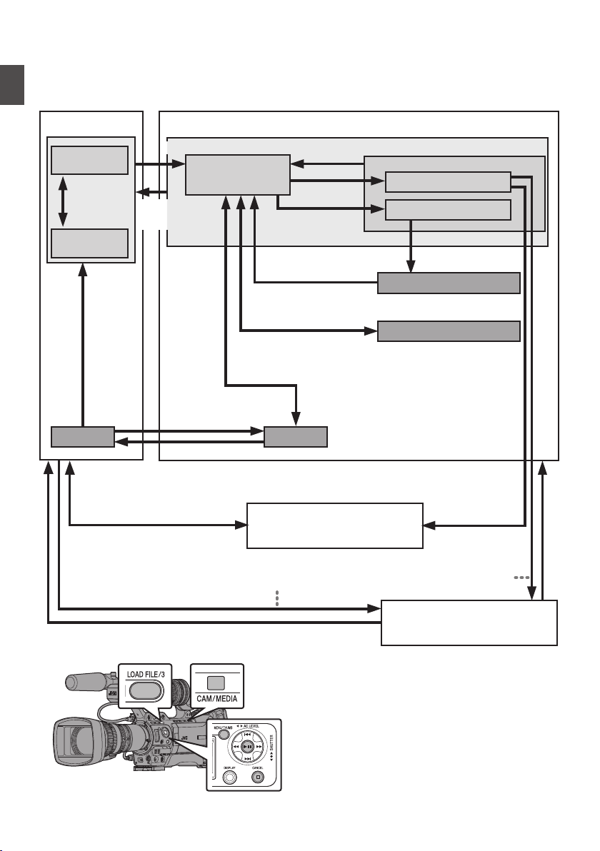
Operation Modes
This camera recorder has four operation modes - Camera mode, Media mode, USB mode and Remote
Edit mode.
.
FTP実行中
Trimming Playback
Normal Playback
[CANCEL]/[MENU/THUMB] Button
FTP in Progress FTP in Progress
Exit FTP
Operation
(Successful)
SDI Input
Switch from
Menu
Camera Input
*
* Selecting a mode other than the Metadata Edit mode via the web browser,
or selecting [Exit] on the [Remote Edit Mode] screen
Connection to PC with USB Cable
Press and hold [CAM/MEDIA]
[CAM/MEDIA]
Button
Press and hold
[CAM/MEDIA]
[CAM/MEDIA] Button
Exit/Cancel FTP Operation (Successful/Failed/Stopped)
(Actions)
Execute [Delete Clips]
File Deletion in Progress
Exit/Cancel File Delete Operation (Successful/Failed/Stopped)
Trimming in Progress
Exit Trimming Operation
(Successful/Failed/Stopped)
[LOAD FILE/3]
Button
Execute [Trim This
Clip]
Media Mode
Thumbnail Display
USB Connection (When the confirmation to change to
USB mode appears and [Change] is selected)
(USB Mass Storage Class)
USB Mode
Playback
Button
Connection disabled on PC
Camera Mode
Remote edit mode
Playback
Execute [FTP Upload]
Upon access via a web browser and selecting [Change] on the [Change to Remote Edit
Mode?] screen on the camera or the web browser
18
Operation Modes
Introduction
Operation Mode Description
Camera Mode
0
This is the camera shooting mode. The camera recorder starts up in Camera mode when
the power is turned on.
0
Camera images are output on the viewfinder and LCD monitor. When a recordable SD card
is inserted, the camera recorder enters the recording standby mode. “STBY” appears on
the operation mode display area of the LCD monitor and viewfinder.
0
Press the [REC] trigger button to start recording.
0
When [System] B [Record Set] B [Record Format] B [System] is set to “HD(SDI In)” or
“SD(SDI In)”, and the device is connected to the [SDI IN] terminal, the SDI input video is
displayed on the LCD monitor or viewfinder. A B
(A P168 [Inputting SDI Signals from an External Device A B] )
Memo :
0
Playback of SD card is not possible in Camera mode. However, you can check the most
recently recorded video clip.
(A P83 [Viewing Recorded Videos Immediately (Clip Review)] )
Media Mode
0
This mode allows you to play back or delete clips recorded on the SD card.
0
When a playable SD card is inserted, the thumbnail or playback screen is displayed on the
viewfinder and LCD monitor.
0
Press and hold the [CAM/MEDIA] selection button to enter the Media mode when you are
not shooting in the Camera mode. Once the camera recorder is in Media mode, thumbnails
of the selected media slot are displayed.
USB Mode
0
This mode allows you to connect to a PC and transfer the files on an SD card to the PC.
(Writing is not allowed)
0
When the camera recorder is connected to a USB cable, the message “Change to USB
Mode?” appears.
Select [Change] and press the Set button to switch to USB mode.
(A P160 [Managing/Editing Clips on a PC] )
0
In USB mode, the camera recorder is recognized by the connected PC as a peripheral drive.
(USB mass storage class only)
Disable the connection on the PC and remove the USB cable from the camera recorder to
switch to Camera mode.
(A P160 [Managing/Editing Clips on a PC] )
Memo :
0
When a USB cable is connected during recording, the message appears after recording
stops.
0
If playback is in progress, the message appears once the files are closed automatically,
such as when playback stops.
0
Files on the PC cannot be written to the SD card.
Remote Edit Mode
0
This mode enables the list display and editing of the recorded clip data through access to
the clip list display page via a web browser on a smartphone, tablet terminal, or PC.
0
When you access via a web browser on a smartphone, tablet terminal, or PC, “It is necessary
to change the camera mode to "Remote Edit Mode". Change the mode.” appears on the
web browser. Also, “Change to Remote Edit Mode?” is displayed on the display screen of
the camera unit.
Selecting [Change] on the camera recorder and pressing the Set button switches to the
Remote Edit mode, and enables display of the clip list and editing of the clip metadata.
(A P184 [ Clip Metadata ] )
(A P187 [Uploading a Recording Clip via a Web Browser] )
Memo :
0
If you access via a web browser on devices such as a smartphone, tablet terminal, or PC
while recording is in progress, the message appears after recording stops.
0
If playback is in progress, the message appears once the files are closed automatically,
such as when playback stops.
Operation Modes
19
Introduction
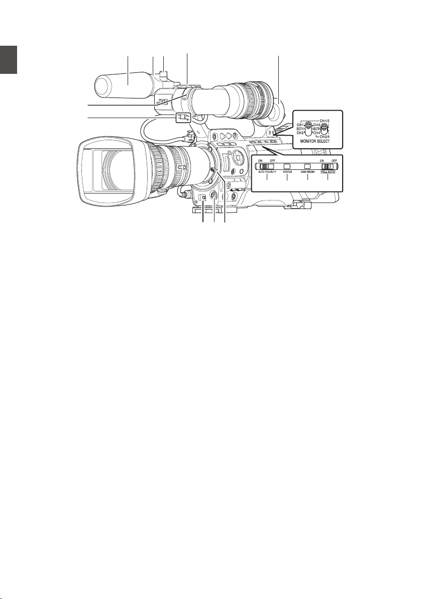
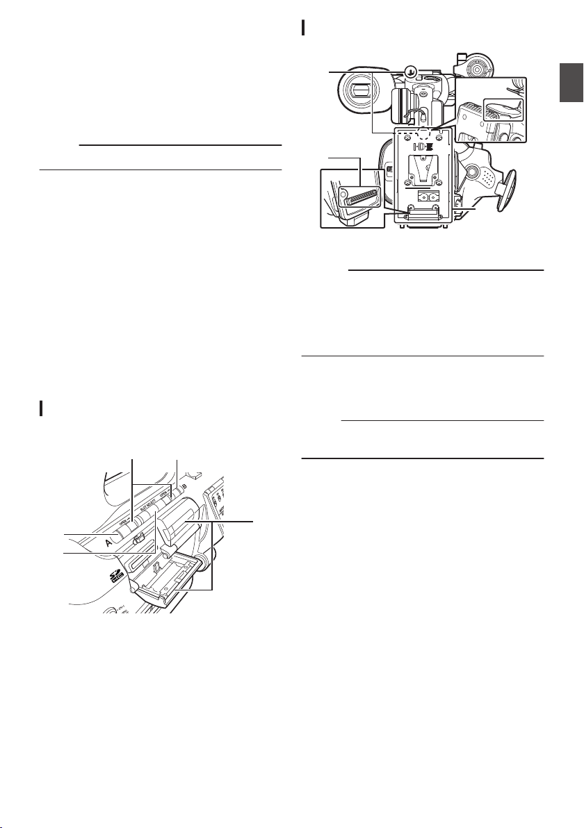
Names of Parts
.
M
O
N
L
B
A
DCE
K
FGHI
J
A
Front Tally Lamp
(A P42 [Tally Lamp] )
(A P206 [Blinking of the Tally Lamp] )
B
Viewfinder Cable Clamp
(A P28 [Attaching the Viewfinder
(Supplied)] )
C
Cross-Shaped Button (JKHI)/Set Button (R)
The function changes according to the
operation status of the camera recorder.
0
During menu operation (all modes)
(A P103 [Basic Operations in Menu Screen] )
Center Set button (R)
:
Confirms menu
items and setting
values
Cross-Shaped Button
(JKHI)
:
Selects menu
items and setting
values
0
During Camera mode
[5/J][K/6][7/H/
ZEBRA][8/I/SPOT
METER]
:
You can also use
it as a user button
by assigning a
specific feature in
the menu setting
to this button.
(A P42 [Assignment of Functions to User
Buttons] )
(A P79 [Setting Zebra Pattern] )
(A P80 [Setting Spot Meter] )
D
[AWB/9] Auto White Balance/User 9 Button
0
Auto White Balance starts up when the
[WHT.BAL B/A/PRESET] switch J on the
operation panel located at the right side of
this unit is set to “A” or “B”.
0
It is used to switch the color temperature of
the preset white balance when the
[WHT.BAL B/A/PRESET] switch J on the
operation panel located at the right side of
this unit is set to “PRESET”.
0
You can also use it as a user button by
assigning a specific feature in the menu
setting to this button.
(A P63 [Adjusting the White Balance] )
(A P42 [Assignment of Functions to User
Buttons] )
E
Lens Lock Lever
(A P28 [Attaching the Lens (Supplied)] )
F
[AUTO FOCUS/11] Autofocus/User 11 Switch
For switching the Autofocus function ON or
OFF. F
You can also use it as a user button by assigning
a specific feature in the menu setting to this
button.
This switch operates only with the supplied lens.
G
[STATUS] Status Screen Display Button
Press the [STATUS] button to display the status
screen on the viewfinder and LCD monitor
during normal screen display (when the menu
screen is not displayed).
H
[CAM/MEDIA] Camera/Media Mode Selection
Button
(A P18 [Operation Modes] )
I
[FULL AUTO ON/OFF] Full Auto Switch
(A P57 [Adjusting the Brightness
Automatically] )
(A P65 [Automatic White Balance Mode
(FAW: Fulltime Auto White balance)] )
20
Names of Parts
Introduction
.
W
T
HOLD
REC
FIX VAR OFF
P
S
Q
d
T
U
Y
W
V
b
a
Z
c
a
e
R
X
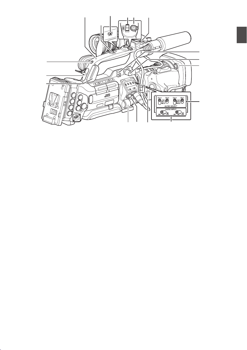
J
[MONITOR SELECT] Audio Monitor Selection
Switch
(A P72 [Audio Output during Recording] )
K
Monitor Speaker (Cheek Pad)
(A P97 [Audio Output during Playback] )
L
Shoe
For mounting separately sold lights and
accessories.
M
Microphone Holder Lock Knob
(A P28 [Attaching the Microphone
(Supplied)] )
N
Microphone Holder
(A P28 [Attaching the Microphone
(Supplied)] )
O
Microphone
(A P69 [Audio Recording] )
P
Back Tally Lamp
(A P42 [Tally Lamp] )
Q
[PHONES] Earphone Connection Terminal
(φ3.5)
(A P72 [Audio Output during Recording] )
R
[HOST] USB Host Terminal
For connecting an USB adapter according to
the intended purpose when you are connecting
the unit to a network.
(A P175 [Camera Setup for Network
Connection] )
S
[LENS] Lens Connection Terminal (12-pin
Connector)
(A P28 [Attaching the Lens (Supplied)] )
T
[INPUT1/INPUT2] Audio Input Terminal 1, 2
(XLR 3-pin x 2)
(A P69 [Audio Recording] )
U
Lens Cable Clamp
(A P28 [Attaching the Lens (Supplied)] )
V
[AUDIO INPUT] Audio Input Signal Selection
Switch 1/2
(A P69 [Audio Recording] )
W
[AUDIO SELECT CH-1~CH-4] Audio Input
Signal Selection Switch 1 to 4
(A P69 [Audio Recording] )
X
Hood Release Button
(A P29 [Attaching/Detaching the Hood A
C] )
Y
Viewfinder Connection Terminal (20-pin)
(A P28 [Attaching the Viewfinder
(Supplied)] )
Z
Accessory Cable Clamp
a
Accessory Mounting Screw Hole (x2)
b
[REC/HOLD] Record Trigger Button/Lock
Switch
Starts/stops recording.
Set the switch to [HOLD] to lock the [REC/
HOLD] Trigger button. However, note that the
other record trigger buttons are not locked.
c
Zoom lever at the Handle F
(A P52 [Using the Zoom Lever at the Handle
F] )
d
[FIX/VAR/OFF] Zoom Speed Switch F
(A P52 [Zoom Operation] )
For switching the zoom speed of the zoom lever
c at the handle.
e
Handle
Names of Parts
21
Introduction

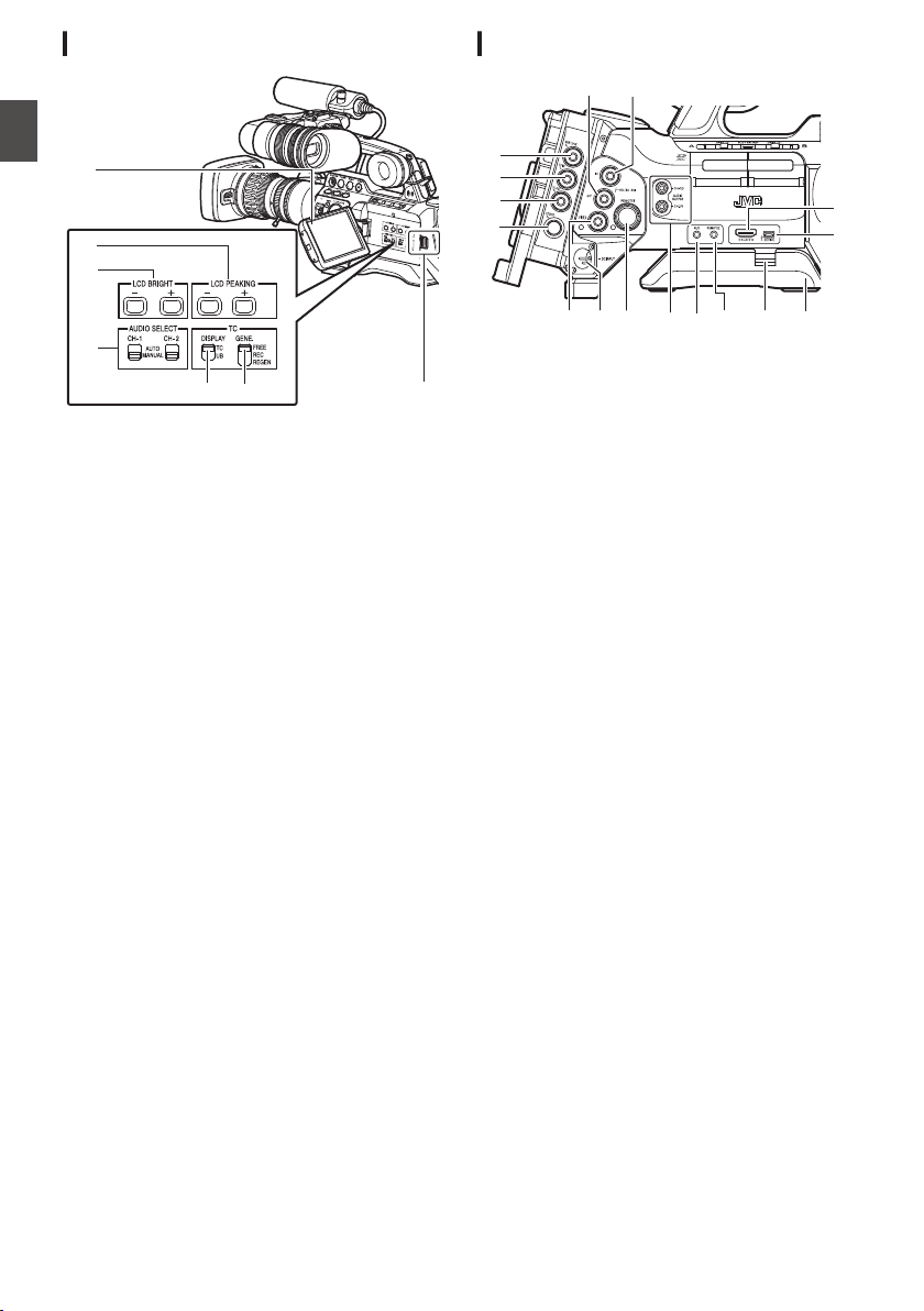
Side Control Panel
.
M
N
O
L
A
B
F
G
H
J
K
I
E
P
Q
D
C
A
[VF BRIGHT] Viewfinder Brightness
Adjustment Knob
(A P40 [Adjusting the Viewfinder] )
B
[VF PEAKING] Outline Adjustment Knob
(A P40 [Adjusting the Viewfinder] )
Memo :
0
This knob is disabled when Focus Assist is in
operation.
(A P55 [Focus Assist Function] )
C
[F.ASSIST/4] Focus Assist/User 4 Button
For switching the focus assist function ON or
OFF.
(A P55 [Focus Assist Function] )
You can also use it as a user button by assigning
a specific feature in the menu setting to this
button.
(A P42 [Assignment of Functions to User
Buttons] )
D
[OIS/1] Optical Image Stabilizer/User 1 Button
For switching the image stabilizer feature mode
ON or OFF. F
You can also use it as a user button by assigning
a specific feature in the menu setting to this
button.
(A P42 [Assignment of Functions to User
Buttons] )
E
[MARKER/2] Marker/User 2 Button
This button toggles ON/OFF the marker, safety
zone, and center mark displays.
You can also use it as a user button by assigning
a specific feature in the menu setting to this
button.
(A P154 [Marker and Safety Zone Displays] )
(A P42 [Assignment of Functions to User
Buttons] )
F
[MENU/THUMB] Menu/Thumbnail Button
0
Displays the menu screen during Camera
mode.
0
Switches between [Main Menu] and
[Favorites Menu] when the [MENU/
THUMB] button is pressed and held down
while the menu screen is displayed.
(A P103 [Basic Operations in Menu Screen] )
0
Displays the menu screen when the button
is pressed during thumbnail display in the
Media mode.
0
Stops playback and displays the thumbnail
screen when the button is pressed during
playback screen display in the Media mode.
G
[ND FILTER] ND Filter Switch
(A P62 [Setting the ND Filter] )
H
[DISPLAY] Display Button
0
Press the [DISPLAY] button to switch to the
display screen during normal screen display
(when the menu screen is not displayed).
(A P36 [Display Screen] )
0
Switches between [Main Menu] and
[Favorites Menu] when the [DISPLAY]
button is pressed while the menu screen is
displayed.
(A P103 [Basic Operations in Menu Screen] )
I
[GAIN L/M/H] Gain Level Switch
(A P59 [Setting the Gain] )
J
[WHT.BAL B/A/PRESET] White Balance
Switch
(A P63 [Adjusting the White Balance] )
K
[POWER ON/OFF] Power ON/OFF Switch and
Indicator Lamp
Turns ON/OFF the power. The indicator lamp
lights up in green when the power is on.
When the power is OFF, “POFF” appears on the
LCD monitor and viewfinder.
Wait for 5 seconds or more to turn on the power
again.
L
[REC/10] Record Trigger/User 10 Button
Starts/stops recording.
You can also use it as a user button by assigning
a specific feature in the menu setting to this
button.
(A P42 [Assignment of Functions to User
Buttons] )
M
[AUDIO LEVEL CH-1/CH-2]/[AUTO]CH-1/
CH-2 Recording Level Adjustment Knob/Auto
Indicator Lamp
(A P69 [Audio Recording] )
N
[CANCEL] Cancel Button
Cancels various settings and stops playback.
22
Names of Parts
Introduction

O
Cross-Shaped Button (JKHI)/Set Button (R)
The function changes according to the
operation status of the camera recorder.
o During menu operation (all modes)
(A P103 [Basic Operations in Menu Screen] )
Center Set button (R) : Confirms menu items
and setting values
Cross-shaped button
(JK)
: Selects menu items
and setting values
o During Camera mode
Shutter operation:
Center Set button (R) : Shutter ON/OFF
Cross-shaped button
(JK)
: Switches shutter
speed when shutter
is ON
Cross-Shaped Button
(HI)
: AE level operation
Memo :
0
When [Camera Function] B [AE LEVEL SW] is
set to “AE LEVEL/VFR”, the cross-shaped
button (HI) is used to set the number of frames
during Variable Frame Rec.
(A P93 [Variable Frame Rec] )
(A P109 [ AE LEVEL SW ] )
P
[LOAD FILE/3] Load File/User 3 Button
Displays the screen for retrieving a picture file.
You can also use it as a user button by assigning
a specific feature in the menu setting to this
button.
(A P158 [Loading a Setup File] )
(A P42 [Assignment of Functions to User
Buttons] )
Q
[MONITOR] Audio Monitor Level Adjustment
Knob
For adjusting the volume of the monitor speaker
and earphone.
Viewfinder
(A P40 [Adjusting the Viewfinder] )
.
ED
A
C
B
A
Viewfinder Slide Lock Ring
For loosening the ring and adjusting the position
of the viewfinder D to the left or right.
B
Eyepiece Focus Ring
For adjusting the visibility.
C
Viewfinder Eyepiece Lock Ring
For loosening the ring and adjusting the
eyepiece position of the viewfinder to the front
or back.
D
Viewfinder
E
Eyepiece
Prevents external light from entering the
viewfinder screen and cameraman’s vision.
Names of Parts
23
Introduction
LCD Monitor
.
B
C
D
E
F
A
G
A
LCD Monitor
(A P38 [Adjusting the LCD Monitor and
Viewfinder] )
B
[LCD PEAKING +/-] LCD Outline Adjustment
Button
(A P39 [Adjusting the LCD Monitor] )
C
[LCD BRIGHT +/-] LCD Display Brightness
Adjustment Button
(A P39 [Adjusting the LCD Monitor] )
D
[AUDIO SELECT CH-1/CH-2 AUTO/MANUAL]
Selection Switch
(A P69 [Audio Recording] )
E
[TC DISPLAY] TC/UB Display Switch
(A P72 [Time Code and User’s Bit] )
(A P73 [Setting Time Code Generator] )
F
[TC GENE.] Time Code Generator Switch
(A P72 [Time Code and User’s Bit] )
(A P73 [Setting Time Code Generator] )
(A P78 [Synchronizing the Time Code with an
External Time Code Generator] )
G
LCD Cover Lock Release Knob
Side Terminal Section
.
JK M N
O
P
HG
A
C
D
E
F
I
B
L
* GY-HM890U/GY-HM890E/GY-HM890CHU/GY-
HM890CHE is used in the illustration here.
A
[HD/SD SDI IN] HD/SD SDI Input Terminal
(BNC) A B
(A P168 [Inputting SDI Signals from an
External Device A B] )
B
[HD/SD SDI OUT] HD/SD SDI Output Terminal
(BNC)
(A P161 [Connecting External Monitor] )
C
[GENLOCK] Genlock Terminal (BNC)
(A P169 [Inputting External Synchronizing
Signals (Genlock)] )
D
[TC IN] Time Code Input Terminal (BNC)
(A P78 [Synchronizing the Time Code with an
External Time Code Generator] )
E
[TC OUT] Time Code Output Terminal (BNC)
(A P78 [Synchronizing the Time Code with an
External Time Code Generator] )
F
[STUDIO] Studio Terminal (Mini
DIN) A B
Connect to this terminal when you are
combining the use of devices such as a
transmission unit manufactured by a different
company.
(A P172 [Displaying Return Videos from an
External Device A B] )
G
[VIDEO OUT] Video Output Terminal (BNC)
(A P78 [Synchronizing the Time Code with an
External Time Code Generator] )
H
[DC INPUT] DC Input Terminal
Input terminal for DC 12 V power supply.
Connect it with an AC adapter.
(A P30 [Using AC Power (DC IN Power)] )
I
[REMOTE1] Remote 1 Terminal
(A P164 [Connecting a Remote Control Unit] )
24
Names of Parts
Introduction
J
[AUDIO OUTPUT CH-1/3, CH-2/4] Audio
Output Terminal (RCA)
Output terminal for audio signals.
0
Input audio signals are output during
Camera mode.
0
Playback audio signals are output during
Media mode.
0
In the SDI signal input mode, audio signals
superimposed with the SDI input are output.
Memo :
0
Alarm audio is not output.
K
[AUX] AUX Input terminal (φ3.5 Stereo Mini
Jack)
(A P69 [Audio Recording] )
L
[REMOTE2] Remote 2 Terminal
(A P164 [Connecting Wired Remote Control] )
M
Shoulder Pad Slide Button
For adjusting the shoulder pad position. Press
this button to adjust the shoulder pad N position
to the front or back.
N
Shoulder Pad
O
[DEVICE] USB Mini Terminal
(A P160 [Managing/Editing Clips on a PC] )
P
[HDMI] HDMI Output Terminal
(A P161 [Connecting External Monitor] )
SD Slot
(A P43 [SD Card] )
.
D
C
E
B
A
A
Card Slot A Status Indicator
B
[SLOT SELECT] Card Slot Selection Button
For switching the active card slot during
shooting and playback.
C
SD Card Cover
D
Card Slot B Status Indicator
E
[OPEN] SD Card Cover Open/Close Knob
Rear Terminal
.
A
A
B
C
A
Shoulder Belt Mount (x2)
For mounting a shoulder belt (sold separately).
Caution :
0
Be sure to use a shoulder belt with the strength
to withstand the weight of this camera recorder.
0
If the shoulder belt is not properly attached, the
camera recorder may fall and cause injuries.
0
Check the instruction manual provided with the
shoulder belt before using.
B
Accessory Connection Terminal A B
Terminal for connecting a KA-M790G
(Multicore Remote Adapter: sold separately) or
other units.
Memo :
0
When using this terminal, make sure that the
Battery Adapter C is removed.
C
Battery Loading Folder
The shape varies across the U and E models.
(A P31 [Using a Battery Pack] )
* The E model is used in the illustration here.
Names of Parts
25
Introduction
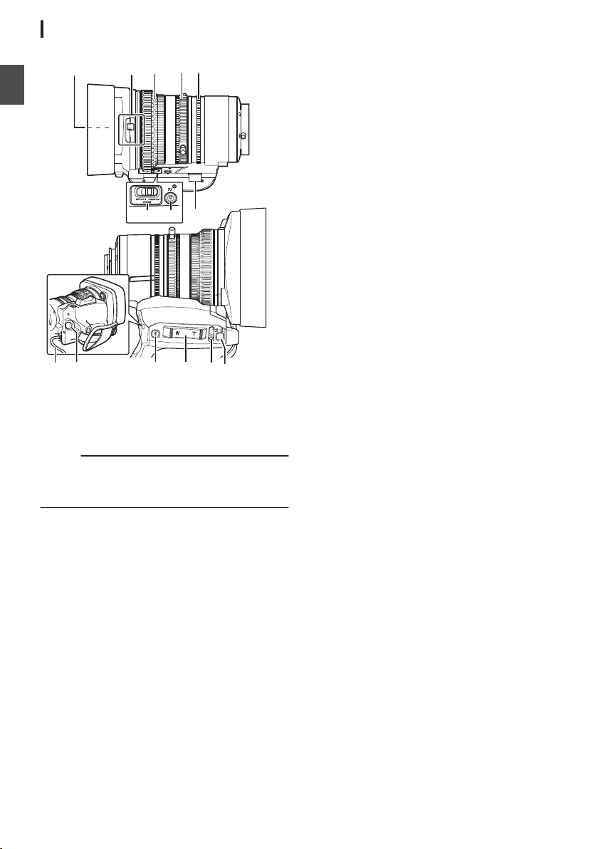
Lens Section A C
.
REC
MNLKJI
E
CAB
FGH
D
A
Filter Built-In Screw
0
Transparent or UV filter for lens protection,
or filters for various effects can be installed.
0
Installable filter types: φ72mmP0.75
Memo :
0
Remove the lens hood when installing the filter.
(A P29 [Attaching/Detaching the Hood A
C] )
B
Lens Cover Open/Close Switch
(A P29 [Opening/Closing the Lens Cover
A C] )
C
Focus Ring
(A P53 [Focus Operation F] )
D
Zoom Ring
(A P52 [Zoom Operation] )
To operate zoom with this ring, set the [ZOOM
SERVO/MANUAL] switch H to “MANUAL”.
E
Iris Ring
(A P58 [Adjusting the Iris] )
To operate the auto iris, set the [IRIS A/M] mode
switch M to “A”.
F
Zoom Servo Connector
This is a connector for connecting a zoom servo
unit (sold separately). When using a separately
sold zoom servo unit, set the [ZOOM SERVO/
MANUAL] switch H to “SERVO”.
G
[F.f] Back Focus Button and Indicator Lamp
(A P41 [Adjusting Back Focus] )
H
[ZOOM SERVO/MANUAL] Zoom Operation
Servo/Manual Switch
Set to “SERVO” in the following cases.
0
When using the grip zoom lever L on the
lens, or the handle zoom lever c on this unit
0
When using a zoom servo unit (sold
separately)
0
When operating remotely from a remote
control unit connected to the [REMOTE1]/
[REMOTE2] terminal or from a web browser
(A P52 [Zoom Operation] )
I
Lens Cable
For connecting to the camera’s [LENS]
connection terminal.
J
[REC] Record Trigger Button
Starts/stops recording.
K
[RET] Return Video Button
Functions as a push autofocus button. F
(A P54 [Setting to Auto Focus Temporarily
(Push Auto Focus)] )
You can also use it as a user button by assigning
a specific feature in the menu setting to this
button.
(A P42 [Assignment of Functions to User
Buttons] )
L
Zoom Lever at the Grip
To operate zoom servo with the zoom lever at
the grip, set the [ZOOM SERVO/MANUAL]
switch 8 to “SERVO”.
(A P52 [Using the Zoom Lever at the Grip] )
M
[IRIS A/M] Iris Mode Switch
Switches the mode of the iris ring 5. Select “A”
to set to auto iris, and “M” to set to manual iris.
N
[IRIS] Iris Momentary Button
When the [IRIS A/M] mode switch M is set to
“M”, Auto Iris mode is enabled while the button
is pressed down.
26
Names of Parts
Introduction
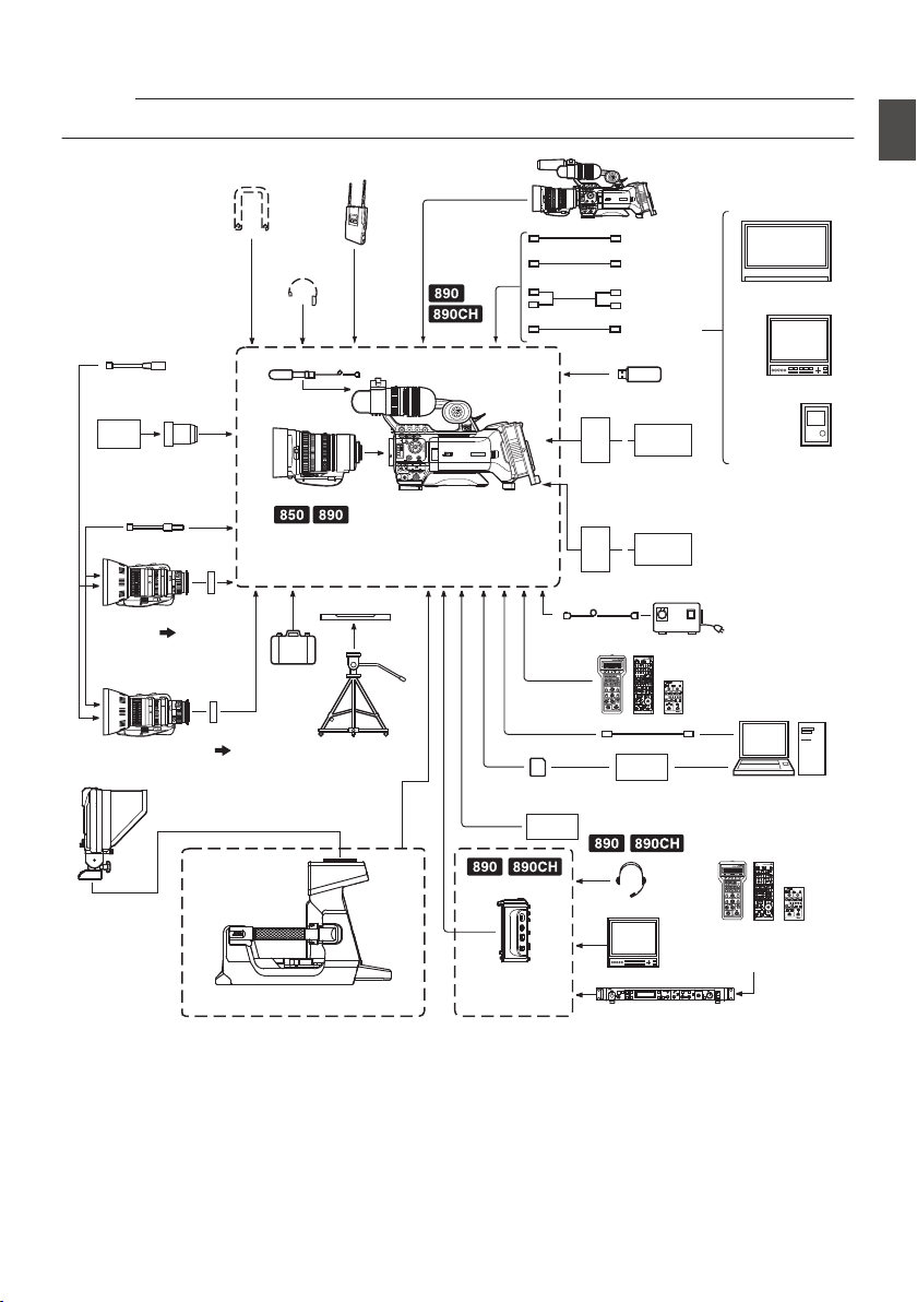
Basic System Diagram
Caution :
0
VF-HP840U does not function even when it is connected to this camera recorder.
.
OPERATE LOCK
OFF FULL
MODE
RM-LP20
REMOTE CONTROL UNIT
GAINSHUTTER
NORMAL
1/120
1/100
1/250
1/500
1/1000
1/2000
EEI
0dB
+3dB
+6dB
+9dB
+12dB
+18dB
ALC
LEVEL GAMMA LEVEL GAMMA KNEE POINT
AUTO
KNEE
WHITE BALANCE
MANUAL PRESET FAW AW A AW B
WHITE PAINT
RB
PAINT AUTO WHITE
TALLY
CALL PREVIEW
MASTER BLACK
IRIS
AUTO
MANUAL
CLOSE OPEN
CALLTALLY
INTERCOM
LEVEL
FULL AUTO F1
SHUTTER
GAIN
F2
F3
MENU/SHUTTER GAIN
PAINT AUTO
BR
W.BAL
AUTO
MANU
WHITE MASTER BLACK
POWER
I
O
IRIS
STEP
SHUTTER
MENU
PUSH-ON
DOWN UP
VARIABLE
PUSH-ON
HIGH
LOW
B
A
PRESET
CLOSE OPEN
MID
DOWN UP
F4
BARS
REMOTE CONTROL UNIT RM-P790
PL Mount
Film Lens
16 mm PL Mount
Film Lens adapter
HZ-CA13U
Zoom Servo Unit
HZ-ZS13B
1/2 Zoom Lens
1/3) : ACM-12
(1/2
1/3) : ACM-17
(2/32/3 Zoom Lens
Anton/Bauer
Battery
(Dionic90)
IDX Battery
(Endura-HL9)
IDX
Battery Charger
XLR 4-pin
AC
Remote Control Unit
RM-LP25U/RM-LP55U/
RM-LP20G
Tripod Base
KA-551U
1/3 AF Zoom Lens
: Gold Mount
: V Mount
Camera Remote Control Unit
RM-HP790DU/RM-HP790DE
Studio Viewfinder
VF-HP790G
Multicore Remote
Adapter
KA-M790G
Studio Adapter
KA-790G
Anton/Bauer
Battery
Charger
Remote Control Unit
RM-LP25U/RM-LP55U/
RM-LP20G
Focus Manual Unit
HZ-FM13㸦FUJINON㸧
HZ-FM15㸦CANON㸧
[HOST]
[AUX]
[SDI IN]
[SDI OUT]
Network Adapter
Wireless Microphone
Receiver
Audio Cable
RCA pin
HDMI Cable
Carrying
Case
Tripod
SD Card
Remote Fiber Adapter KA-F790
SD Card Reader
USB Cable
AC Adapter
Non-linear Editing
System
Microphone
Monitor
Monitor
SDI Cable BNC
Earphone
Shoulder Belt
Headset
Battery Mount
Standard Package
Camera Recorder
External Recording
Device
Composite Cable
BNC
Monitor
Mount Converter
Mount
Converter
U model
U model
E model
E model
* Models with an E suffix are for the European market and the UL Listing mark is not applicable.
Basic System Diagram
27
Introduction
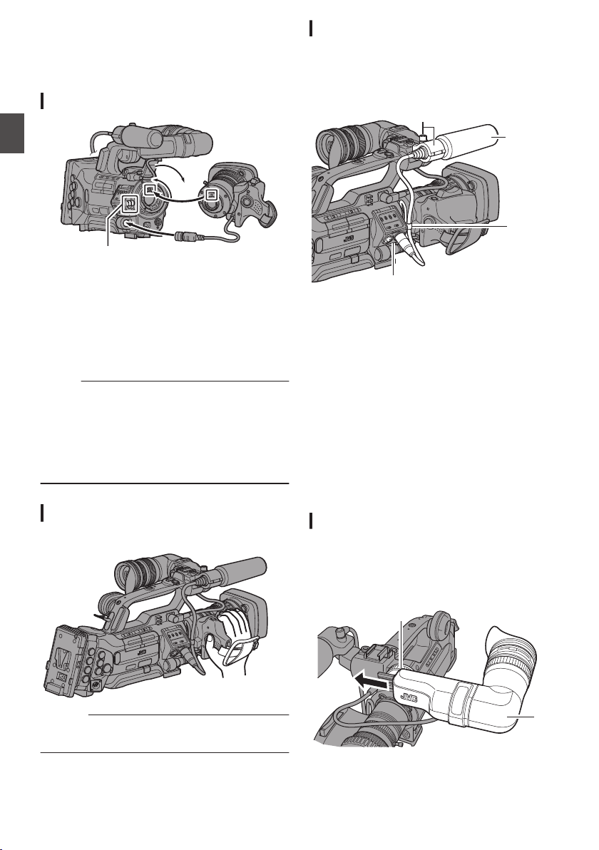
Settings and Adjustments
Before Use
.
Attaching the Lens (Supplied)
.
1
2
3
4
5
1
Loosen the mount ring.
2
Attach the zoom lens such that the pin
matches the hole of the mounting area.
3
Tighten the mount ring.
4
Connect the cable connector.
5
Attach the lens cable to the clamp.
Memo :
0
To attach or detach the zoom lens, set the
[POWER ON/OFF] switch on this unit to “OFF”.
0
Tighten the mount ring completely. If it is not fully
tightened, the lens may drop or the back focus
may be out of alignment.
0
Lens is supplied for GY-HM890U, GY-HM890E,
GY-HM850U, and GY-HM850E.
Adjusting the Grip Belt A C
Adjust the grip belt.
.
Caution :
0
If the grip is loose, the camera recorder may fall
off resulting in injuries or malfunction.
Attaching the Microphone (Supplied)
You can attach the supplied microphone to the
microphone holder.
The supplied microphone uses a phantom power
supply.
.
4
5
1, 3
2
1
Turn the knob on the microphone holder
anticlockwise to loosen and open the
microphone holder.
2
Place the microphone in the microphone
holder.
3
Turn the knob on the microphone holder
clockwise to secure the microphone.
4
Connect the microphone cable to the
[INPUT1] or [INPUT2] terminal.
5
Pin the microphone cable to the clamp.
6
Perform the settings for the phantom mic
correctly.
(A P69 [Audio Recording] )
Attaching the Viewfinder (Supplied)
1
Slide the viewfinder in the direction of the
arrow to attach it.
2
Turn the slide lock ring to secure the
position of the viewfinder.
.
1
2
28
Settings and Adjustments Before Use
Preparations
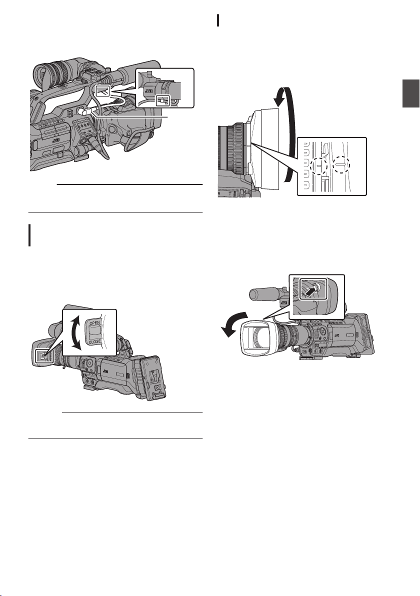
3
Attach the viewfinder cable to the
viewfinder terminal.
4
Pin the viewfinder cable to the clamp.
.
3
4
Memo :
0
To attach or detach the viewfinder, set the
[POWER ON/OFF] switch on this unit to “OFF”.
Opening/Closing the Lens Cover A
C
Use the lens cover open/close switch to open or
close the lens cover.
Before shooting, open the lens cover.
When this camera recorder is not in use, close the
lens cover to protect the lens.
.
Caution :
0
Do not press against the lens cover with force.
Doing so may damage the lens or the cover.
Attaching/Detaching the Hood A C
Attaching the Hood
Align the markings on the camera recorder and
hood; turn the hood in the direction of the arrow until
it is locked.
.
Detaching the Hood
0
Remove the hood when attaching a filter,
teleconverter or wide converter to the front of the
lens.
0
While pressing the hood release button, turn the
hood in the anti-clockwise direction to remove it.
.
Settings and Adjustments Before Use
29
Preparations
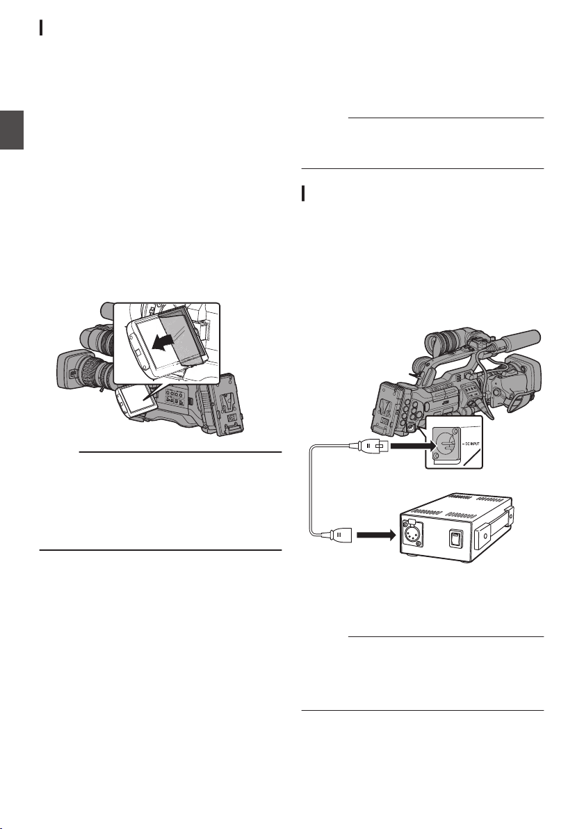
Attaching the Anti-reflective Film
Attach the supplied anti-reflective film onto the LCD
monitor if necessary, such as when you are
recording in the day or outdoors.
Doing so helps to cut down reflection of outside
light, thus improving the visibility.
1
Wipe off any dirt, dust or stains on the
surface of the LCD monitor.
2
Peel off the backing of the anti-reflective
film halfway.
Pay attention to prevent fingerprints from being
left on the adhesive face.
3
Attaching the Anti-reflective Film
0
Attach the anti-reflective film by aligning it
with the corners of the LCD monitor, while
ensuring that there are no air bubbles.
0
Squeeze the air bubbles out.
0
In case if the anti-reflective film is not
correctly attached, you can wash and reuse
it.
.
Memo :
0
Do not press the LCD monitor surface with
excessive force when attaching the film.
0
For additional orders of the anti-reflective film,
please consult the authorized dealer from which
this camera recorder was purchased, or our
service center.
Anti-reflective film model: LS43131
Power Supply
To use this camera recorder, you can attach a
battery pack or connect an AC adapter to it.
(A P31 [Using a Battery Pack] )
(A P30 [Using AC Power (DC IN Power)] )
Caution :
0
Set the [POWER ON/OFF] switch to “OFF”
before changing the power supply that operates
this camera recorder.
Using AC Power (DC IN Power)
Use the AC adapter (sold separately) to operate
the camera recorder with AC power.
1
Connect the DC cable of the AC adapter to
the [DC INPUT] terminal of the camera
recorder.
Check that the power of this unit and that of the
AC adapter are both set to “OFF”, followed by
connecting according to the diagram.
.
2
Turn on the power of the AC adapter,
followed by setting the [POWER ON/OFF]
switch of this unit to “ON”.
Power will be supplied to the camera recorder.
Caution :
0
Do not insert or remove the DC cable during
recording.
0
Do not use power supply of high voltage
fluctuation, containing noise such as ripple, or
with insufficient capacity.
30
Settings and Adjustments Before Use
Preparations
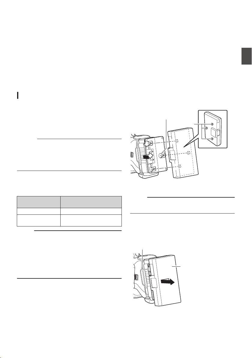
Built-In Battery
0
The date/time and time code data are stored
using the built-in rechargeable battery.
0
When power is connected to the camera
recorder, the built-in battery always gets
charged. When the power is disconnected, the
battery gradually discharges.
0
The battery will be totally discharged if left
unused for 3 months and the date/time and time
code data will be reset. When this happens, set
the [POWER ON/OFF] switch to “ON” to display
the [Initial Setting] screen, then set the date/
time.
(A P34 [Initial Settings] )
Using a Battery Pack
Recommended Batteries
U model : Dionic90 (Anton/Bauer)
E model : Endura-HL9 (IDX)
* Models with an E suffix are for the European
market and the UL Listing mark is not applicable.
Caution :
0
Make use of the recommended batteries. Heavy
batteries may fall off if not used correctly.
0
For details on how to charge the battery, please
refer to the [instruction manual] of the battery in
use.
Battery Operating Time
The following are the approximate times for
continuous operation on fully-charged batteries.
Battery
Continuous Recording
Time (At 25 °C)
Dionic90 (U model) Approx. 2.8 h
Endura-HL9 (E
model)
Approx. 2.7 h
Memo :
0
Actual operating times may differ depending on
the age of the battery, charging condition, and
operating environment.
0
Operating time is shortened in cold
environment.
0
The operating time may shorten when power
zoom is used, accessories are connected, or
when the LCD monitor is frequently used.
Precautions for the Battery Operation
0
Do not remove the battery when the [POWER
ON/OFF] switch is “ON”.
0
Do not insert or remove the DC cable when the
battery is in use.
0
Leaving the camera recorder unused with the
battery inside will deplete the battery power
even if you set the [POWER ON/OFF] switch to
“OFF”. Remove the battery if you are not using
the camera recorder.
Attaching/Detaching the Battery (U Model)
Use the Dionic90 (Anton/Bauer) battery.
1
Align the battery guide pins (x3) with the
battery adapter guide hole, and insert them
directly.
.
Guide Pins
Guide Hole (x3)
2
Slide the battery in the direction indicated
by the arrow until a “click” sound is heard.
Memo :
0
If the guide pins are not inserted straight, the
battery will not be attached correctly.
3
Detaching the Battery
Press down the release lever and slide the
battery toward you to detach it from the camera
recorder.
.
Battery
Release Lever
Power Supply
31
Preparations
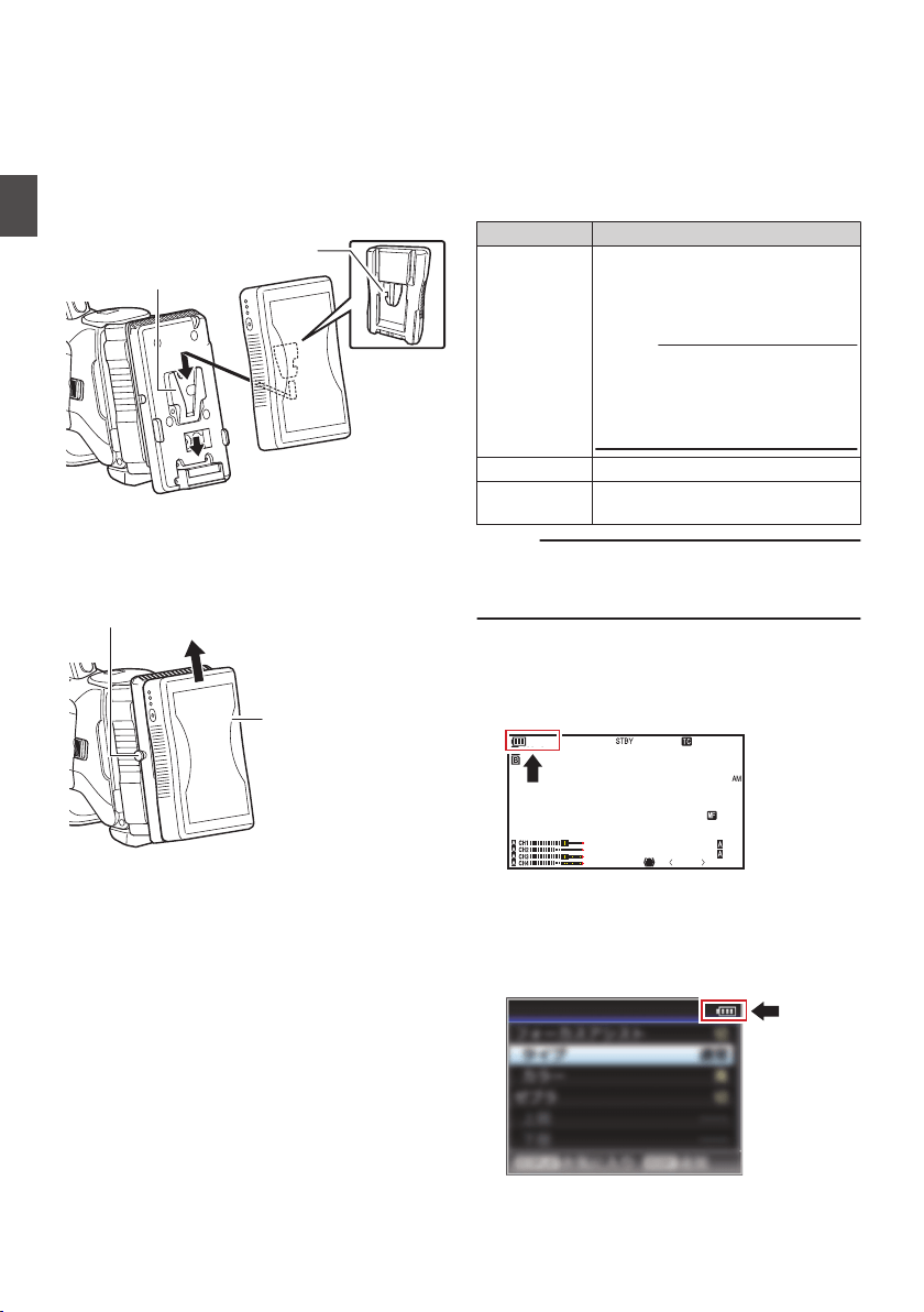
Attaching/Detaching the Battery (E Model)
Use the Endura-HL9 (IDX) battery.
1
Attach the battery.
Face the terminal downward and attach the V
mount of the battery onto the V mount
attachment bracket of the camera recorder.
2
Press down the battery until it snaps into
place.
.
V Mount
V Mount Attachment Bracket
3
Detaching the Battery
Press down the release lever and slide the
battery upward to detach it from the camera
recorder.
.
Battery
Release Button
Precautions for Batteries
0
Store the battery in a cool and dry place when
not in use. Do not expose the battery to high
temperatures (such as in a car under direct
sunlight). This will cause battery leakage and
shorten the battery life.
0
Operating time is shortened if the battery
terminal is dirty.
0
If the operating time shortens drastically even
after charging, the battery may be reaching the
end of its life. Replace the battery with a new
one.
Power Status Display
Viewfinder Screen and LCD Monitor
The power status is indicated on areas such as the
display screen and the menu screen. When the
value and unit appear in yellow, it is a warning
indicating that the supply voltage of the DC power
or the remaining battery level is low.
Display Description
B 12.0V
B 100min
C 30%
4 RES
I 16.0V
Currently powered by a battery.
When the battery power runs out,
the battery mark appears hollow,
and “RES” (yellow) is displayed.
Memo :
0
You can set the display using
[LCD/VF] B [Display Settings]
B [Battery].
(A P123 [ Battery ] )
G
Currently powered by DC power.
H
A warning display when the supply
voltage of the DC power is low.
Memo :
0
If the battery in use is not a recommended one,
the battery mark which indicates the battery
level may not appear.
Display Screen
(A P145 [Display Screen in Camera Mode] )
(A P151 [Display Screen in Media Mode] )
.
100min
50min
282min
P13000K
1/100
F1. 6
0
dB
AE+6
ND 1 /64
5 . 6 f t
12 :34 :56
Jan 24 , 2014
00: 00:00.00
1920x1080
60 i HQ
Menu Screen
(A P104 [Display and Description of the Menu
Screen] )
.
Shooting Assist
32
Power Supply
Preparations
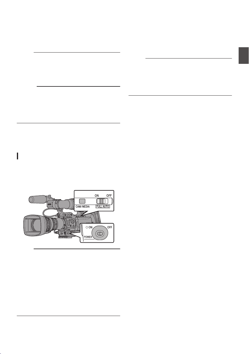
Warnings by Lamp and Warning Tone
Warning status is indicated by tally lamp and
warning tone.
0
The front and back tally lamps of the camera
recorder appear blinking.
0
The warning tone is output from the monitor
speaker or [PHONES] terminal.
Memo :
0
If you continue to use the camera recorder while
the power warning is displayed, the camera
recorder will stop automatically when the battery
or supplied voltage from the DC power becomes
lower.
Caution :
0
The remaining battery power and time are
displayed as they are from the battery
information. Accurate data may not be displayed
depending on the battery condition. Replace the
battery as soon as possible when the remaining
battery power and time are low.
Turning On/Off the Power
Turning On the Power
1
Set the [POWER ON/OFF] switch to “ON”.
0
The camera recorder starts up in Camera
mode and is ready for shooting.
0
The power status indicator lights up in green.
.
Memo :
0
The camera recorder always start up in Camera
mode when the [POWER ON/OFF] switch is set
to “ON”.
0
Pressing the [CAM/MEDIA] selection button on
the camera recorder each time switches the
mode.
0
Setting [System] B [Record Format] B [System]
to “HD(SDI In)” or “SD(SDI In)” switches the
camera recorder to the SDI Input mode.
A B
(A P18 [Operation Modes] )
Camera Mode
Camera images are output on the viewfinder and
LCD monitor. If a recordable SD card is inserted,
the camera recorder switches to the recording
standby mode, and “STBY” is displayed on the
operation mode display area of the LCD monitor
and viewfinder.
Press the [REC] trigger button to start recording.
Memo :
0
Playback of SD card is not possible in the
Camera mode. However, you can check the
most recently recorded video clip using the clip
review feature.
(A P83 [Viewing Recorded Videos
Immediately (Clip Review)] )
Media Mode
This mode allows you to play back or delete clips
recorded on the SD card.
When a playable SD card is inserted, the thumbnail
or playback screen is displayed on the viewfinder
and LCD monitor.
USB Mode
0
This mode allows you to connect to a PC and
transfer the files on an SD card to the PC.
(Writing is not allowed)
0
When the camera recorder is connected to a
USB cable, the message “Change to USB
Mode?” appears.
Select [Change] and press the Set button to
switch to USB mode.
0
In USB mode, the camera recorder is
recognized by the connected PC as a peripheral
drive. (USB mass storage class only)
Disable the connection on the PC and remove
the USB cable from the camera recorder to
switch to Camera mode.
(A P160 [Managing/Editing Clips on a PC] )
Power Status Display
33
Preparations
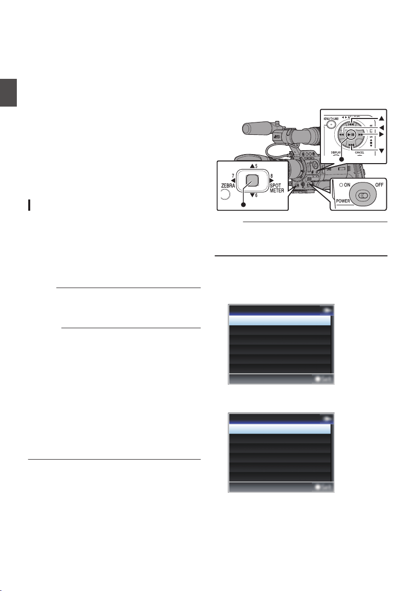
Remote Edit Mode
0
This mode enables the list display and editing of
the recorded clip data through access to the clip
list display page via a web browser on a
smartphone, tablet terminal, or PC.
0
When you access via a web browser on a
smartphone, tablet terminal, or PC, “It is
necessary to change the camera mode to
"Remote Edit Mode". Change the mode.”
appears on the web browser. Also, “Change to
Remote Edit Mode?” is displayed on the display
screen of the camera unit.
Selecting [Change] on the camera recorder and
pressing the Set button switches to the Remote
Edit mode, and enables display of the clip list
and editing of the clip metadata.
(A P184 [ Clip Metadata ] )
(A P187 [Uploading a Recording Clip via a Web
Browser] )
Turning Off the Power
Sets the camera recorder to the recording standby
or stop mode.
1
Set the [POWER ON/OFF] switch to “OFF”.
2
Remove the battery and the power to the
[DC INPUT] terminal (when not in use for a
long time).
Memo :
0
The [POWER ON/OFF] indicator lamp lights up
in green when the camera recorder is shutting
down, and turns off when shutdown is complete.
Caution :
0
Do not set the [POWER ON/OFF] switch to
“OFF” during recording. Check that the
operation mode display is “STBY” or “STOP”
before you turn off the power.
0
If you have mistakenly set the [POWER ON/
OFF] switch to “OFF” during recording, wait for
5 seconds or more before you turn on the power
again.
0
When turning off the power, first set the
[POWER ON/OFF] switch of the camera
recorder to “OFF”. Do not remove the battery or
turn off the power of the AC adapter while the
[POWER ON/OFF] switch is set to “ON”.
Initial Settings
When the power is first turned on, the Initial Setting
screen for performing the initial settings in the
camera recorder appears.
Set the date/time of the built-in clock in the [Initial
Setting] screen.
All operations are disabled until initial settings are
complete.
.
Memo :
0
It is recommended to use the AC adapter as the
power supply.
0
Be sure to close the lens cover.
1
Set the [POWER ON/OFF] switch to “ON”.
A language selection screen appears.
0
For U models
.
Español
Français
English
Language
0
For E models
.
Pусский
Español
Italiano
Deutsch
Français
English
Language
34
Turning On/Off the Power
Preparations
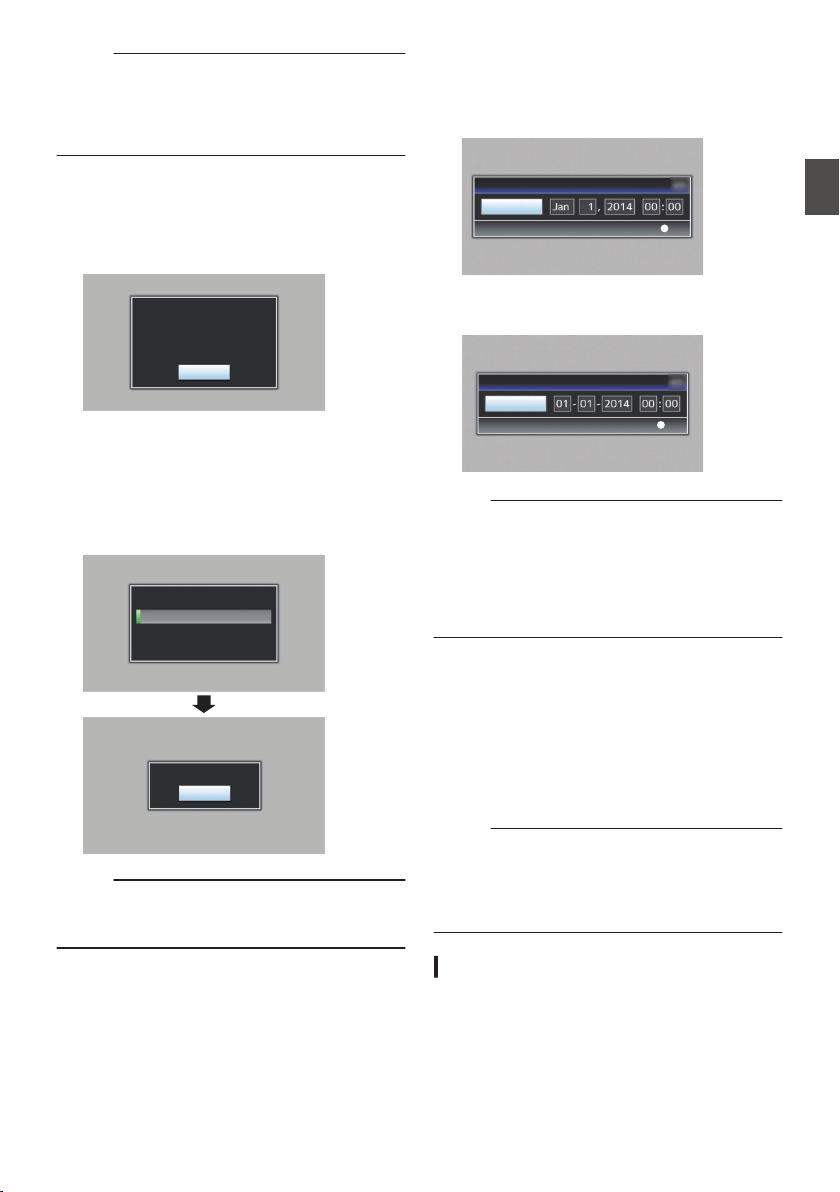
Memo :
0
The selectable languages vary according to the
destination.
0
The menus and messages on the screen of the
LCD monitor or viewfinder are displayed in the
selected language.
2
Move the cursor using the cross-shaped
button (
JK) to select a language to use,
followed by pressing the Set button (
R).
The Initial Setting screen appears.
.
Diagnose
The Time is about 6 minutes.
with lens cap.
try self diagnosis attaching
Prior to the first operation,
3
Ensure that the lens cover is closed, and
press the Set button (
R).
0
Self-diagnosis starts.
0
A progress bar appears, and “Complete
Diagnosis” appears when the diagnosis is
complete.
.
Close
Complete Diagnosis
Don't Remove Lens Cap.
Diagnosing...
Memo :
0
It takes about 6 minutes to complete the
diagnosis. During the diagnosis, do not operate
or turn off the camera recorder.
4
Press the Set button (
R) after confirming
the exit screen.
The [Initial Setting] screen appears.
0
For U models
.
Set
UTC-05:00
Initial Setting
0
For E models
.
Set
UTC
Initial Setting
Memo :
0
The [Initial Setting] screen appears when the
power is turned on for the first time and when the
power is turned on after the built-in battery is fully
discharged.
0
The configured date/time data is saved in the
built-in rechargeable battery even if the power is
turned off.
5
Set the time zone and date/time.
A
Move the cursor with the cross-shaped button
(HI) and select the setting item.
B
Change the values with the cross-shaped
button (JK).
6
Press the Set button (
R) after setting is
complete.
The clock is set to 0 seconds of the input date/
time.
Memo :
0
The configured date/time data can be displayed
on the LCD monitor and viewfinder and be
recorded to the SD card.
0
The value of the year can be set in the range of
“2000” to “2099”.
Changing the Time after Initial Setting
Setting the Date/Time
(A P131 [ Date/Time ] )
1
Select [System]
B [Date/Time].
The [Date/Time] screen appears.
Initial Settings
35
Preparations
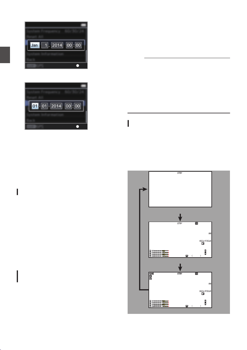
0
For U models
.
Set
System
0
For E models
.
Set
System
2
Set the date and time.
A
Move the cursor with the cross-shaped button
(HI) and select the setting item.
B
Change the values with the cross-shaped
button (JK).
3
Press the Set button (
R) after setting is
complete.
The clock is set to 0 seconds of the input date/
time.
Changing the Display Style
You can change the display style of the date/time
on the menu.
Setting the Date Display (Date Style)
(A P124 [ Date Style ] )
The date display can be changed in [LCD/VF] B
[Display Settings] B [Date Style].
Setting the Time Display (Time Style)
(A P124 [ Time Style ] )
The time display can be changed in [LCD/VF] B
[Display Settings] B [Time Style].
Date/Time Display in Each Operation
Mode
0
During Camera mode:
Date/time of the built-in clock is displayed.
0
During Media mode:
Shooting date/time of the clip being played back
is displayed.
Displays on the LCD
Monitor and Viewfinder
You can display the camera status, media
information, zebra pattern, and various markers in
the video image on the LCD monitor and viewfinder
screen during shooting.
Memo :
0
When [Main Menu] B [A/V Set] B [Video Set] B
[HDMI Out Character]/[SDI Out Character]/
[VIDEO Out Character] is set to “On”, the display
screen and menu screen are also displayed in
the video image of the video signal output
terminal.
(A P126 [ HDMI Out Character ] )
(A P126 [ SDI Out Character ] )
(A P126 [ VIDEO Out Character ] )
Display Screen
Display Screen in Camera Mode
0
The display switches between three screen
types with every press of the [DISPLAY] button.
(Display 0 B 1 B 2 B 0)
0
Press the [STATUS] button to switch to the
status screen.
.
P13000K
1/100
F1. 6
0dB
AE+6
ND 1 /64
12 :34 :56
Jan 24 , 2014
00: 00:00.00
5 . 6 f t
100min
50min
282min
P13000K
1/100
F1. 6
0dB
AE+6
ND 1 /64
12 :34 :56
Jan 24 , 2014
00: 00:00.00
1920x1080
60i HQ
5 . 6 f t
Display 2 screen
Display 1 screen
Display 0 screen
36
Initial Settings
Preparations
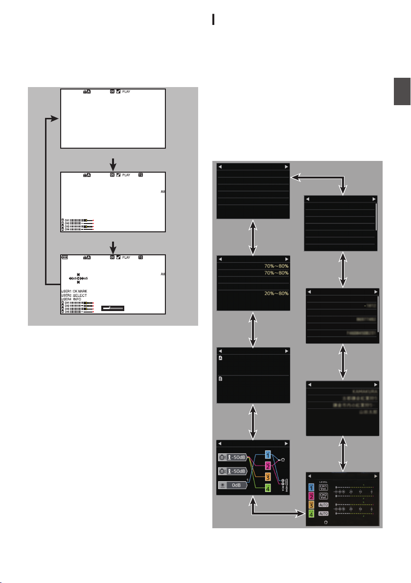
Display Screen (VF/LCD) in Media Mode
(A P151 [Display Screen in Media Mode] )
0
This is the screen display during clip playback in
Media Mode.
0
The display switches between three screen
types with every press of the [DISPLAY] button.
(Display 0 B 1 B 2 B 0)
.
1000/ 2000
12 :34 :56
Jan 24 , 2014
00: 00:00.00
1920x1080
60 i HQ
1000/ 2000
282min
12 :34 :56
Jan 24,2014
00: 00:00.00
1920x1080
60i HQ
1000/ 2000
Display 2 screen
Display 1 screen
Display 0 screen
Status Screen
0
This screen allows you to check the current
settings.
0
To display the status screen, press the
[STATUS] button in the normal screen.
0
The status display differs according to the
operation mode (two types).
(A P18 [Operation Modes] )
0
Press the [STATUS] button to switch to the
display screen.
0
Press the [MENU] button at each status screen
(other than the [Camera] and [Audio Level]
screen) to enter the setting screen.
0
Use the cross-shaped button (HI) to switch
screens as follows:
.
192.168.0.1
HM890
Zebra
USER7
USER6
None
None
USER5
Focus Assist
USER4
Load Picture File
USER3
Marker
USER2
OIS
USER1
USER Switch Set
Live Streaming
MAC Address
IP Address
Passphrase
WPA2
Security Type
SSID
P2P
Ty p e
Network
Creator
Description
Title2
Title1
Planning Metadata
Mix
CH1/2
Audio Level
Audio
4ch
4ch
Audio
Audio
60i(HQ)
60i(HQ)
1920x1080
1920x1080
QuickTime(MPEG2)
QuickTime(MPEG2)
Format
Format
Record Format
Histogram
Off
Safety Zone
16:9
Aspect Marker
Zebra 2
Zebra 1
LCD/VF
AE Level
AE LEVEL SW
12dB
GAIN H
6dB
GAIN M
0dB
GAIN L
None
FAW
Standard
Shooting Mode
Camera
Displays on the LCD Monitor and Viewfinder
37
Preparations
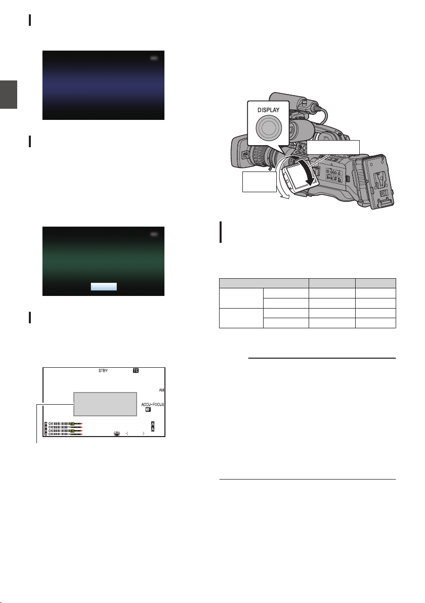
USB Mode Screen
This screen displays the USB mode.
.
USB Mode
Remote Edit Mode Screen
This mode enables the list display and editing of
the recorded clip data through access to the clip list
display page via a web browser on a smartphone,
tablet terminal, or PC.
(A P184 [ Clip Metadata ] )
(A P187 [Uploading a Recording Clip via a Web
Browser] )
.
Exit
Remote Edit Mode
Warning Display
Warning display is displayed in the display screen
(Camera mode, Media mode).
(A P202 [Error Messages and Actions] )
.
P13000K
1/100
F1. 6
0dB
AE+6
ND 1 /6 4
12 :34 :56
Jan 24 ,2014
00:00:00.00
5 . 6 f t
Warning Display Area
Adjusting the LCD Monitor
and Viewfinder
You can monitor video images on this camera
recorder using the viewfinder, LCD monitor, or
both.
.
Inverted
LCD
Normal LCD
Displays on the LCD Monitor and
Viewfinder Screen (VF)
When [LCD/VF] B [LCD + VF] is set to “Off”
(A P120 [ LCD + VF ] )
LCD Monitor Status LCD Display VF Display
LCD closed Normal LCD OFF ON
Inverted LCD ON OFF *
LCD opened Normal LCD ON OFF *
Inverted LCD ON OFF *
* Turns on when [LCD/VF] B [LCD + VF] is set to
“On”.
Memo :
0
Press and hold the [DISPLAY] button for 2 seconds
to turn ON/OFF the LCD monitor.
0
The function to switch between LCD monitor and
viewfinder displays by pressing the [DISPLAY]
button can be canceled by opening/closing or
rotating the LCD monitor.
0
The viewfinder screen is always displayed when
[LCD/VF]
B
[LCD + VF] is set to “On”.
0
You can display both the LCD monitor and
viewfinder screens at the same time by setting
[LCD/VF]
B
[LCD + VF] to “On”.
(A P120 [ LCD + VF ] )
38
Displays on the LCD Monitor and Viewfinder
Preparations
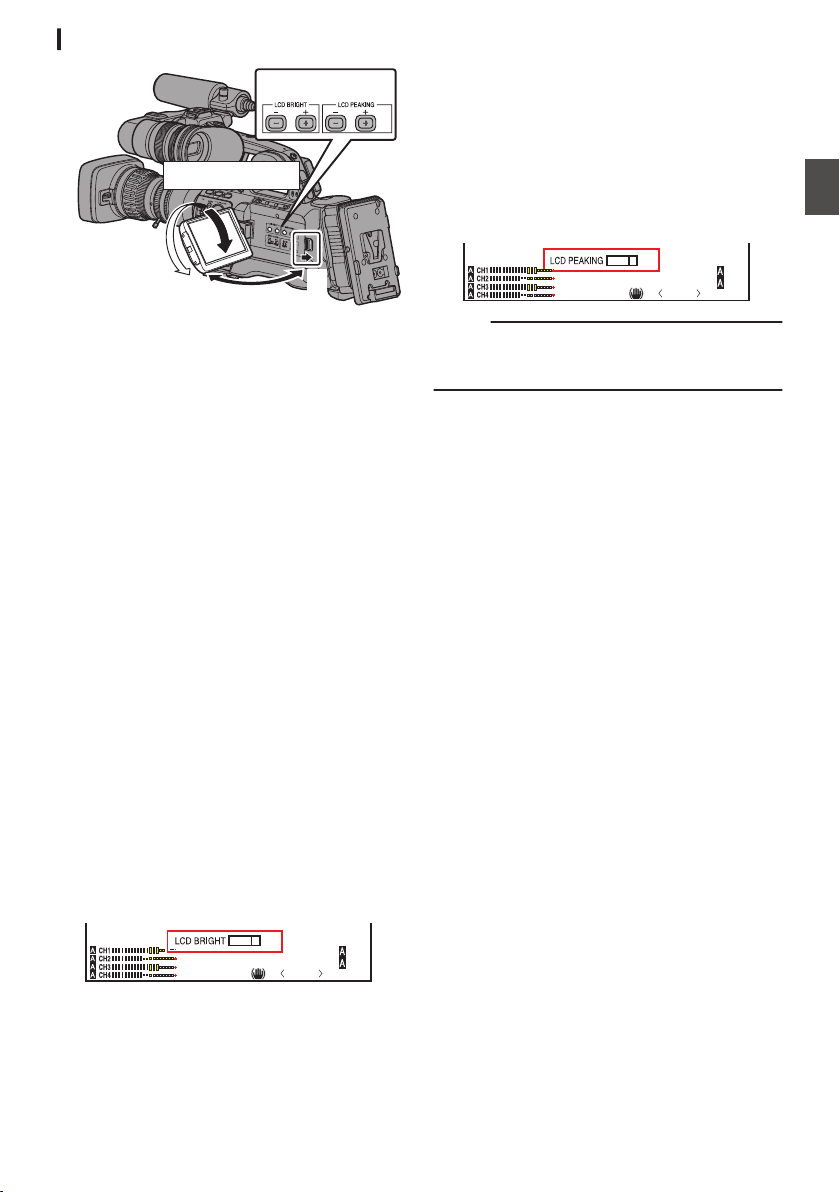
Adjusting the LCD Monitor
.
2
1
Tilt 90 degrees downward
Tilt 180 degrees upward
3
1
Slide the LCD cover lock release knob to
open the LCD monitor.
2
Incline the LCD monitor to a position that
enables easy viewing.
Rotate the LCD monitor to adjust the angle.
0
While the LCD monitor is open, you can
rotate it 180 degrees upward or 90 degrees
downward.
0
Rotating the LCD monitor 180 degrees
upward enables you to see the screen from
the lens side. To display the image when it is
viewed from the opposite direction (mirror
image), perform setting as follows.
Set [Main Menu] B [LCD/VF] B [LCD
Mirror] to “Mirror” B Set button (R)
(A P120 [ LCD Mirror ] )
3
Adjust the brightness, contour, and
contrast of the LCD monitor.
You can change the angle and brightness of the
LCD monitor according to your usage condition.
Changing the brightness of the screen will not
affect the recorded images.
Adjusting the Brightness
Use the [LCD BRIGHT +/-] button to adjust the
brightness of the LCD monitor.
0
The [+] button brightens the monitor and the
[-] button darkens it.
0
Press the [+] and [-] buttons simultaneously
to return to standard settings.
0
During adjustment, the brightness level is
displayed on the LCD monitor.
.
P13000K
1/100
F1. 6
0dB
AE+6
ND 1 /64
+5
Adjusting the Contour
Use the [LCD PEAKING +/-] button to adjust the
contour of the LCD monitor.
0
The [+] button increases contour correction
and the [-] button decreases contour
correction.
0
Press the [+] and [-] buttons simultaneously
to return to standard settings.
0
During adjustment, the contour level is
displayed on the LCD monitor.
.
P13000K
1/100
F1. 6
0dB
AE+6
ND 1 / 64
+5
Memo :
0
During Focus Assist operation, the contour
correction effect on the LCD monitor will be
temporarily disabled.
Adjusting the Contrast
Use the [LCD Contrast] menu to adjust the
contrast of the LCD monitor.
0
Adjust using [Main Menu]
B
[LCD/VF]
B
[LCD
Contrast].
0
Increasing the value increases the contrast.
[Setting Values: +10 to -10] (Default value: 0)
Adjusting the LCD Backlight
0
Adjust using [Main Menu] B [LCD/VF] B
[LCD Backlight].
(A P120 [ LCD Backlight ] )
0
When using the camera recorder at a bright
location such as one subject to outside light,
setting to “Bright” helps to ease viewing.
0
You can also adjust the backlight using the
user button assigned with the “LCD
Backlight” function.
(A P42 [Assignment of Functions to User
Buttons] )
Adjusting the LCD Monitor and Viewfinder
39
Preparations
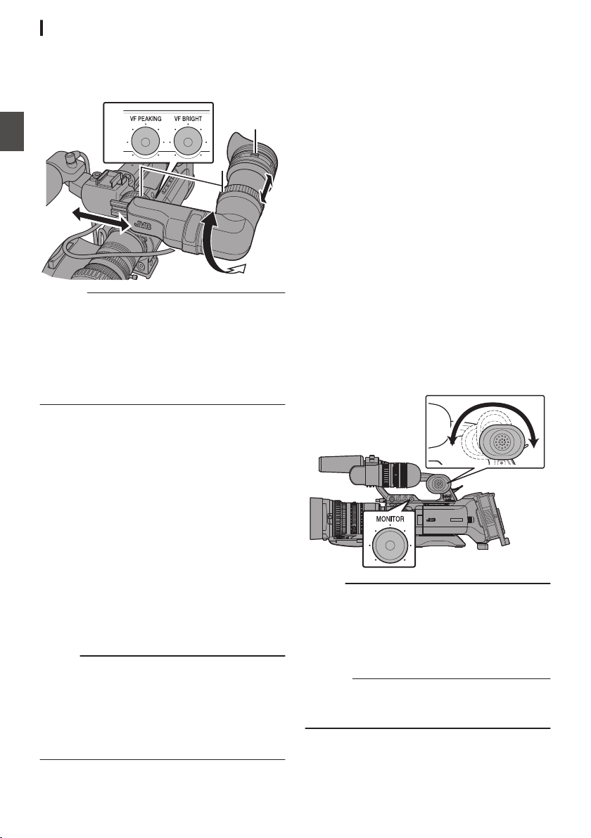
Adjusting the Viewfinder
You can change the brightness and peaking of the
viewfinder screen according to your usage conditions.
Changing the brightness of the screen will not affect the
recorded images.
.
2
1
3
Caution :
0
A high-definition viewfinder is used on this
camera recorder in order to provide an accurate
focusing environment. Due to the characteristic
of the display device, colors may appear on the
images when you blink your eyes. This is not a
malfunction. It does not affect the recorded
images, SDI output, VIDEO output, or HDMI
output.
1
Loosen the two rings, and adjust the
position and angle of the viewfinder to one
that eases viewing.
2
Turn the visibility adjustment lever to
adjust the visibility.
Turn the visibility adjustment lever to sharpen
the image on the viewfinder screen.
3
Adjust the brightness, contour, and
contrast of the viewfinder screen.
Adjusting the Brightness
Use the [VF BRIGHT] adjustment knob to adjust
the brightness of the viewfinder screen.
Adjusting the Contour
Use the [VF PEAKING] adjustment knob to
adjust the outline of the viewfinder screen.
Memo :
0
When [Main Menu] B [LCD/VF] B [LCD + VF] is
set to “Off”, operate after switching to the
viewfinder display by pressing the [DISPLAY]
button for 2 seconds or longer.
0
During Focus Assist operation, the contour
correction effect on the viewfinder will be
temporarily disabled.
Adjusting the Contrast
Use the [VF Contrast] menu to adjust the
contrast of the viewfinder screen.
0
Adjust using [Main Menu] B [LCD/VF] B [VF
Contrast].
0
Increasing the value increases the contrast.
[Setting Values: +10 to -10] (Default value:
0)
Displaying in Black and White
You can display the viewfinder screen in black
and white.
0
[Main Menu] B [LCD/VF] B [VF Color] item
B Press Set button (R) B Select “Off” B
Press Set button (R).
(A P120 [ VF Color ] )
Adjusting the Monitor
Speaker
The monitor speaker can be rotated 180 degrees.
Adjust according to the position of your ear.
.
Memo :
0
Adjust the volume level of the monitor speaker
using the [MONITOR] level adjustment knob on
the operation panel located at the right side of
the camera recorder. Various warning alarm
tones may also be output repeatedly.
(A P206 [Warning Tone] )
Caution :
0
The rotation angle of the monitor speaker is 180
degrees. Do not over-rotate the monitor
speaker.
40
Adjusting the LCD Monitor and Viewfinder
Preparations
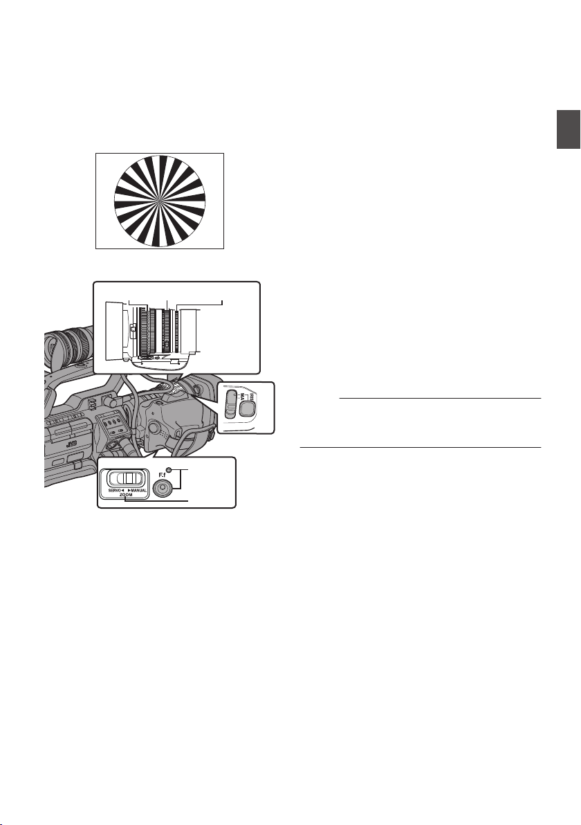
Adjusting Back Focus
When the lens is first attached, adjust the back
focus of the lens if the focus is not clear when
zoomed to the telephoto or wide angle end.
0
Place an object 3 m and above away from the
camera recorder.
0
The Siemens Star Chart is most suitable as the
subject.
.
Siemens Star Chart
.
6, 9
2
3, 84
2, 10
1
1
Set the [ZOOM SERVO/MANUAL] switch to
“MANUAL”.
2
Press and hold down the [IRIS] button, and
press the [F.f] back focus button until the
indicator lamp lights up (approx. 1.5
seconds).
3
Turn the zoom ring to set the lens to the
maximum telephoto position.
4
Turn the focus ring to adjust the focus of
the object.
5
Turn the zoom ring to set the lens to the
maximum wide angle position.
6
Adjust the back focus using the iris ring to
set the focus on the subject.
7
Repeat steps
3 to 6 a few times until focus
is set on both the telephoto and wide-angle
ends.
8
Turn the zoom ring and check if the image
is blurry at the telephoto end at the 20 mm
scale mark.
9
If blurring occurs, turn the iris ring to adjust
the focus. (It is recommended to set the
zoom ring near the 40 mm scale mark.)
10
Press the [F.f] back focus button until the
indicator lamp goes off (approx. 0.5
second).
Memo :
0
The iris is fixed at the maximum position. Adjust
the lighting, shutter and gain to obtain an
appropriate video level.
Adjusting Back Focus
41
Preparations
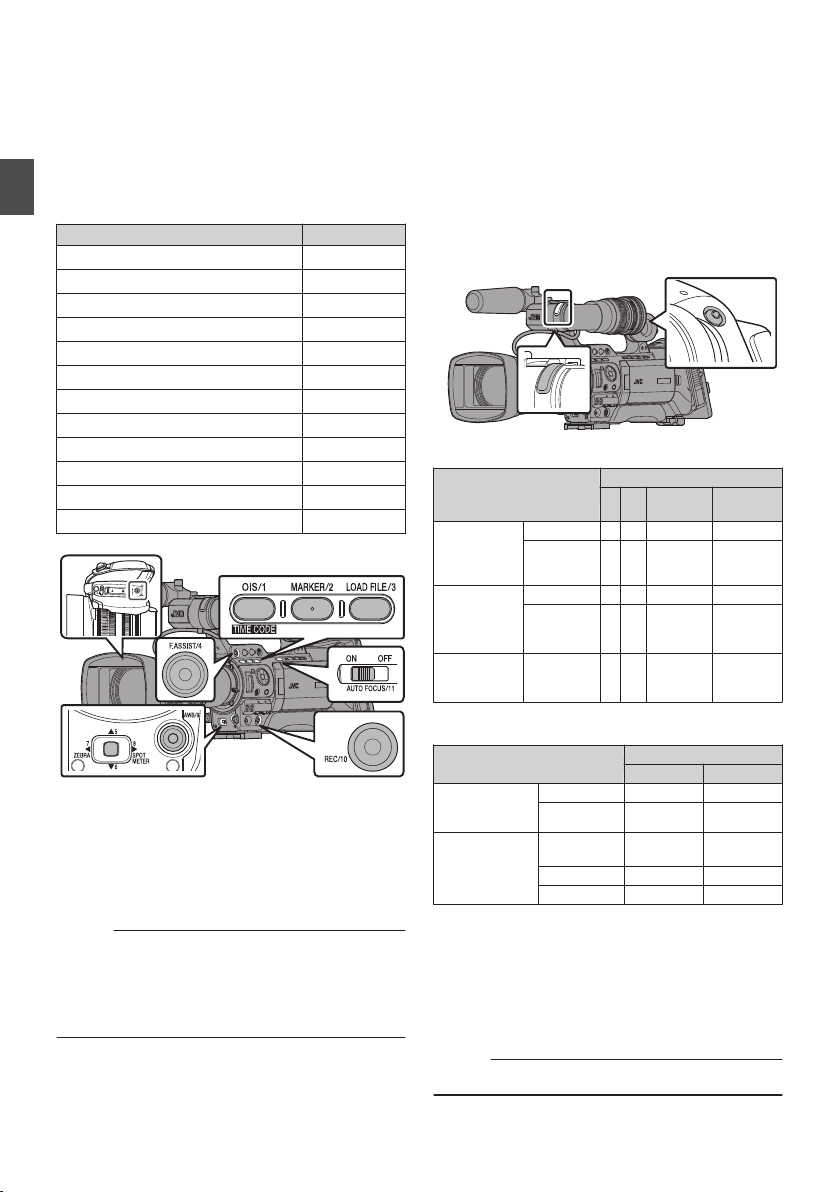
Assignment of Functions
to User Buttons
You can assign functions to the following buttons
and use them as user buttons.
By assigning functions to the buttons, the usability
of the camera recorder can be enhanced.
Perform settings in the menu items corresponding
to each button.
Button Menu Item
[OIS/1] Button [USER1]
[MARKER/2] Button [USER2]
[LOAD FILE/3] Button [USER3]
[F.ASSIST/4] Button [USER4]
[J/5] Button [USER5]
[K/6] Button [USER6]
[7/H/ZEBRA] Buttons [USER7]
[8/I/SPOT METER] Buttons [USER8]
[AWB/9] Button [USER9]
[REC/10] Button [USER10]
[AUTO FOCUS/11] Button [USER11]
[RET] Button [Lens RET]
.
1
Assign functions to the buttons from the
menu.
Set items in [Main Menu] B [Camera Function]
B [User Switch Set] B [USER1] to [USER11],
and [Lens RET].
(A P111 [User Switch Set Item] )
Memo :
0
Operations of the user buttons are interlocked
with the menu settings.
0
When the menu screen is displayed, these
buttons function as the menu operation buttons.
(A P103 [Basic Operations in Menu Screen] )
Tally Lamp
This is the indicator lamp for recording and
warning.
The operation changes according to the menu
settings.
The lamp blinks when the battery or remaining
space on the SD card is low. (Camera mode only)
* Set using [Main Menu] B [System] B [Front
Tally]/[Back Tally].
(A P130 [Front Tally/Back Tally] )
.
0
When [Tally System] is set to “Internal”
Menu Setting
Front Tally/Back Tally
Off Rec Live
Streaming
Rec/Live
Streaming
Information on
Camera
Recorder
Functions
Warning -
J J J
Alarm -
o o o
Camera
Recorder
Recording
Status
Recording -
R
-
R
Special
Recording in
Progress *1
R
-
R
Live Streaming
Status
Live
Streaming in
Progress
- -
R R
0
When [Tally System] is set to “Studio”
Menu Setting
Front Tally/Back Tally
Off On
Information on
Camera Recorder
Functions
Warning -
J
Alarm -
o
Input from Remote
Control Unit
CALL -
o
*2
PROGRAM -
R
PREVIEW -
R
R
: Lights up
o
: Blinks once in 1 second
J
: Blinks twice in 1 second
*1 Paused state during special recording ([Clip
Continuous]).
(A P89 [Clip Continuous Rec] )
*2 Back tally only
Memo :
0
Blinking takes priority over lighting up.
42
Assignment of Functions to User Buttons
Preparations
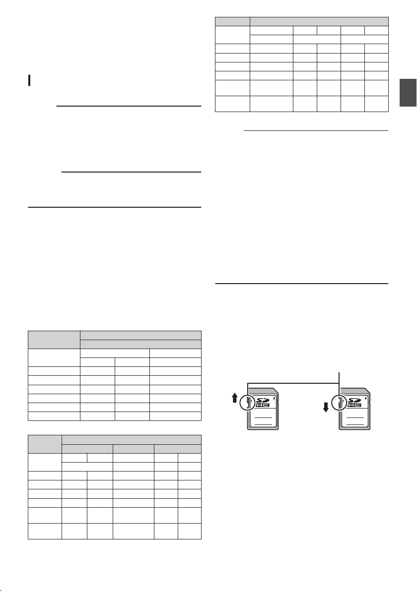
SD Card
This camera recorder saves the recorded images
and audio sound on the SD card (sold separately)
in the card slot.
Usable Cards
Use a Class 6/10 SD card.
Memo :
0
Depending on the recording format, SD card
with Class 4 or higher performance can also be
used.
Some recording formats supports only the use
of cards with Class 10 or higher.
(A P50 [Selecting a Recording Format] )
Caution :
0
Using cards other than those from Panasonic,
TOSHIBA or SanDisk may result in recording
failure or data loss.
Estimated Recordable Time of SD Cards
0
The estimated recordable time is only a guide.
Differences may occur depending on the SD
card in use and the battery condition.
0
The following is the recording time during audio
4ch recording. However, the duration is for
audio 2ch recording in the case of AVCHD. The
recording time is longer for 2ch recording.
(A P133 [ W Resolution ] )
(A P134 [ Y Resolution ] )
(A P133 [ W Frame & Bit Rate ] )
(A P134 [ Y Frame & Bit Rate ] )
QuickTime/MP4/MXF
MPEG2/HD
SP HQ
720p 1080i 720p/1080i
4GB 20 16 12
8GB 40 32 24
16 GB 80 64 48
32 GB 160 130 96
64 GB (SDXC) 320 260 192
128 GB (SDXC) 640 520 384
(Unit: minute)
QuickTime
H.264/HD H.264/SD H.264/Web
XHQ UHQ - HQ LP
1080i/1080p 480i/576i 960p 480p
4GB 8 12 40 120 240
8GB 17 24 80 240 480
16 GB 35 48 160 480 960
32 GB 70 96 320 960 1920
64 GB
(SDXC)
140 192 640 1920 3840
128 GB
(SDXC)
280 384 1280 3840 7680
(Unit: minute)
AVCHD
HQ HQ SP LP EP
1920x1080p 1920x1080i 1440x1080i
4GB 16 19 25 46 82
8GB 33 39 50 95 168
16 GB 67 78 100 190 336
32 GB 135 156 200 380 672
64 GB
(SDXC)
270 312 400 760 1344
128 GB
(SDXC)
540 632 800 1520 2688
(Unit: minute)
Memo :
0
If the SD card contains files recorded by devices
other than this camera recorder or files that are
saved from a PC, the recordable time may be
shorter or data may not be properly recorded.
0
For each file format, up to 600 clips can be
recorded to one SD card on this camera
recorder. When 600 clips are recorded to one
card, the remaining space is displayed as 0 min
regardless of the estimated recordable time,
and no further recording can be performed.
0
When [Main Menu] B [System] B [Record Set]
B [Record Format] B [Format] is set to
“AVCHD”, up to 4000 clips can be recorded to
one SD card.
0
When the file format is set to “AVCHD”, up to
4000 clips can be recorded to one SD card.
Write-Protect Switch on the SD Card
A
Slide the write-protect switch upward to enable
writing or deleting.
B
Slide the write-protect switch downward to
prevent writing or deleting. (Images in the card
are protected.)
.
AB
Write/Delete Enabled Write/Delete Disabled
Write-Protect Switch
SD Card
43
Preparations
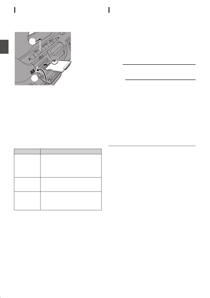
Inserting an SD Card
This camera recorder comes with two card slots
(Slot A and B) for video/audio recording and
playback.
.
1
2
3
1
Open the SD card cover by sliding the SD
card cover knob of the slot to insert the SD
card in the direction indicated by the arrow.
2
Insert an SD card from the end with the
notched corner.
The status indicator of the card slot to which the
card was inserted lights up in red.
3
Close the SD card cover.
Card Slot Status Indicator
The following table shows the respective states of
slot A and B.
Lamp Slot Status
Lights up in
red
The inserted SD card is being
accessed. (writing/reading data)
Do not turn off the power of the
camera recorder or remove the SD
card.
Lights up in
green
On standby. The inserted SD card
can be used for recording or
playback.
Light goes out
0
SD card is not inserted.
0
An unusable card is inserted.
0
An SD card is inserted but a
different slot is selected.
Removing the SD Card
1
Check that the SD card to be removed is not
being accessed (status indicator of the
card slot lights up in red).
2
Open the SD card cover by sliding the SD
card cover knob of the slot in the direction
indicated by the arrow.
3
Push the SD card and remove it from the
slot.
4
Close the SD card cover.
Memo :
0
When both slots are inserted with usable SD
cards, the previously selected slot is used.
Caution :
0
Data may be lost if you turn off the power of the
camera recorder or remove the SD card when it
is being accessed. All data recorded on the
card, including the file that is being accessed,
may be corrupted. Be sure to check whether the
status indicator is lit in green or turned off before
you turn off the power or remove the SD card.
0
If you mistakenly remove the card when it is
being accessed, reinsert the card only after the
status indicator goes off.
0
The SD card may not be recognized if you insert
and remove the card within a short time. When
this happens, remove the card and wait for a few
seconds before you reinsert.
44
SD Card
Preparations
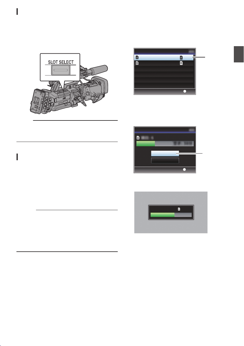
Switching the SD cards
When both card slots are inserted with SD cards,
you can use the [SLOT SELECT] button to switch
the card to use.
When the memory on an SD card is full during
recording, data recording automatically switches to
the other card.
.
Memo :
0
The [SLOT SELECT] button is disabled during
recording or playback. Cards will not be
switched even if you press the button.
Formatting (Initializing) SD Cards
When the following cards are inserted, [!FORMAT]
appears at the remaining media display area.
Format the card using the camera recorder menu.
0
Unformatted SD cards
0
SD cards formatted under different
specifications
* For details of the menu operation, refer to “[Basic
Operations in Menu Screen] P 103”.
Caution :
0
Be sure to format the SD card on this camera
recorder. SD cards formatted on a PC and other
peripheral equipment cannot be used on this
camera recorder.
0
[!RESTORE] appears at the remaining media
display area when an SD card that requires
restoring is inserted.
1
Select [System]
B [Media] B [Format
Media].
(A P130 [ Format Media ] )
2
Select the slot of the SD card to be
formatted and press the Set button (
R).
.
2
Set
Format Slot
Format Slot
Format Media
3
The status of the selected SD card appears.
4
Select [Format] and press the Set button
(
R).
.
4
Set
Cancel
Format
Format Media
5
Formatting starts.
.
Formatting...
SD Card
45
Preparations
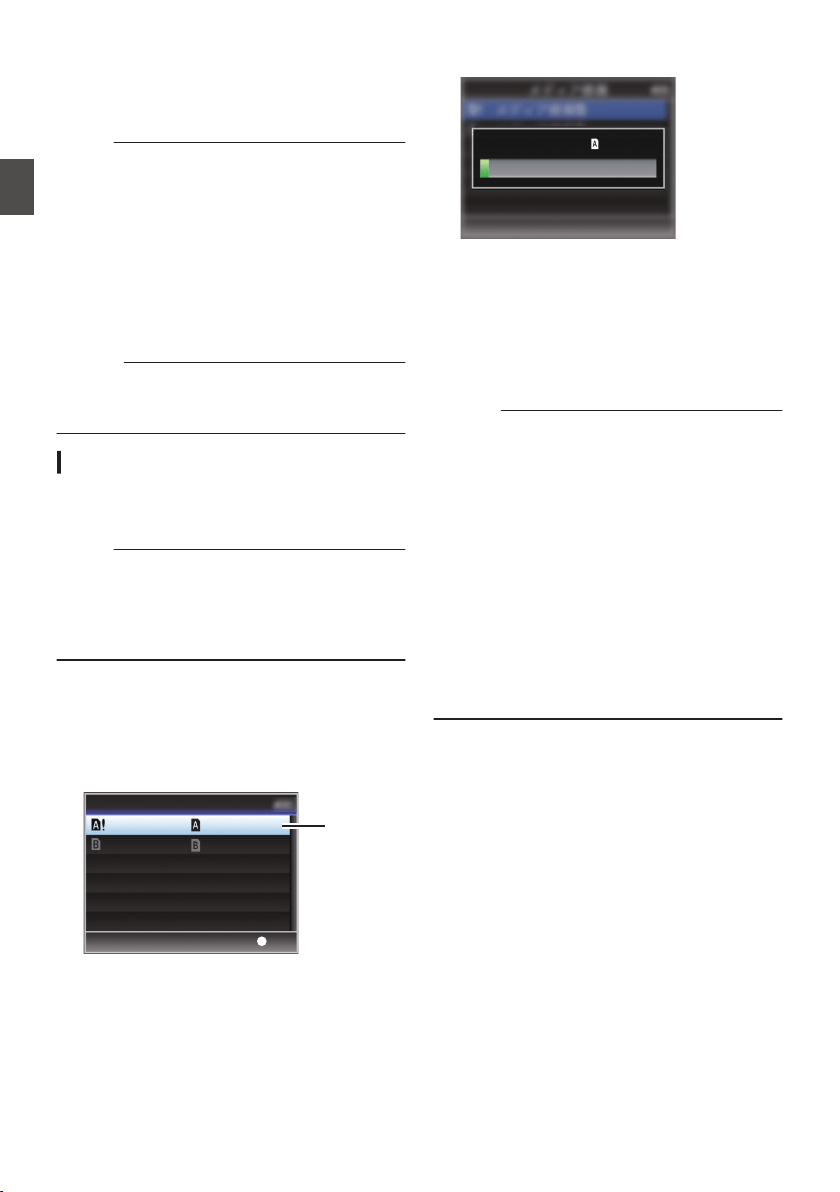
6
Formatting is complete.
When formatting is complete, “Complete” appears
and the camera recorder returns to the [Format
Media] screen.
Memo :
0
During formatting, menu operation is
unavailable but you can start recording.
However, this is only available when a
recordable SD card is inserted in the other slot.
0
Formatting cannot be performed in the following
cases.
0
Recording is in progress on the SD card to be
formatted.
0
SD card is not inserted.
0
Write-protect switch of the SD card is set (z
is displayed).
Caution :
0
If you format the SD card, all data recorded on
the card, including video data and setup files,
will be deleted.
Restoring and Updating the SD Card
It is necessary to restore the SD card if an
abnormality occurs to the data in the card due to
some reasons.
Memo :
0
[!RESTORE] appears at the remaining media
display area when an SD card that requires
restoring is inserted.
0
Executing this function while [!RESTORE] is not
displayed updates the data inside the SD card.
1
Select [System]
B [Media] B [Restore
Media].
(A P130 [ Restore Media ] )
2
Select the SD card to be restored and press
the Set button (
R).
.
2
Set
Restore Slot
Restore Slot
Restore Media
3
Restoring starts.
.
Restoring...
4
Restoring is complete.
0
When restoring is complete, “Complete”
appears and the camera recorder returns to the
[Restore Media] screen.
0
When no media that requires restoring is
inserted, the camera recorder returns to the
[Media] menu screen.
Caution :
0
[Restore Media] can only be selected in Camera
mode. However, it cannot be selected while the
camera recorder is recording. Select [Restore
Media] in Camera mode when the camera
recorder is not recording.
0
[Restore Media] does not restore the SD card to
its original states completely. If restoring fails,
replace or format the SD card. Take note that
formatting erases all the information inside the
SD card.
0
Restoring cannot be performed in the following
cases.
0
Camera recorder is recording in progress.
0
SD card is not inserted.
0
Write-protect switch of the SD card is set (z
is displayed).
46
SD Card
Preparations
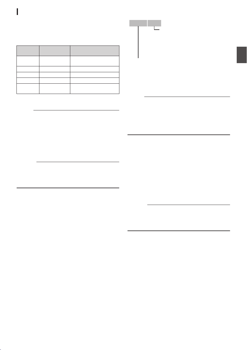
Clips Recorded to SD Cards
Folders in the SD Card
The captured image is recorded into different
folders according to the [System] and [WFormat]/
[YFormat] settings.
System
WFormat/
YFormat
Record Folder
HD QuickTime(
MPEG2)
DCIM or PRIVATE/JVC/
CQAV*
HD MP4(MPEG2) PRIVATE/JVC/BPAV
HD/Web AVCHD PRIVATE/AVCHD
HD MXF(MPEG2) PRIVATE/JVC/CMAV
HD/SD/
Web
QuickTime(H.
264)
DCIM or PRIVATE/JVC/
CQAVC*
* Select which folder to record to from the menu.
(A P136 [ Recording in DCIM Folder ] )
Memo :
0
By formatting (initializing) the SD card from the
[Format Media] menu on the camera recorder,
folders required for recording in the current
[System] settings will be generated.
0
When the [System] settings and
[QuickTime(MPEG2)] settings are changed,
folders required for recording in those settings
will be automatically generated.
Caution :
0
When a clip inside the folder is moved or deleted
using the Explorer (Windows) or Finder (Mac),
recording to the SD card may fail if formatting
(initializing) of the card is not performed.
Clip (Recorded Data) and Clip Name
0
When recording is stopped, the images, audio
and accompanying data which are recorded
from start to stop are recorded as one “clip” on
the SD card.
0
An 8-character clip name is automatically
generated for the recorded clip.
(“Clip Name Prefix” + “Clip Number”)
0
When [Main Menu] B [System] B [Record Set]
B [Record Format] B [WFormat] is set to
“AVCHD”, the clip name generated consists of
only the Clip Number (5-digit number).
(A P133 [ W Format ] )
Example: In the case of QuickTime/MP4/MXF
.
ABCG0001
This is set to “xxxG” (“xxx” denotes the last 3
digits of the serial number) by default.
Clip Name Prefix (any four alphanumeric characters)
The Clip Number can be reset in
the menu.*
A number in automatic
ascending order is assigned in
the recording order.
Clip Number
* [Clip Set] B [Reset Clip Number]
(A P137 [ Reset Clip Number ] )
Memo :
0
Before recording starts, you can set any
characters for the clip name prefix by using
[Main Menu] B [System] B [Record Set] B [Clip
Set] B [Clip Name Prefix].
(A P137 [ Clip Name Prefix ] )
0
Changes cannot be made after recording.
Recorded Clips
0
The recorded materials may be split into several
files but they can be played back continuously
on the camera recorder.
0
Clips may be recorded across the two SD cards
in card slots A and B depending on the recording
time of the clip.
0
When copying videos in MP4 file format to a
HDD using a PC, it is recommended to use [JVC
ProHD Clip Manager Software], which is found
in the supplied disc, to maintain continuity.
Caution :
0
A clip recorded across several cards cannot be
played back continuously. Continuous playback
is only possible when the recording is made on
one card.
SD Card
47
Preparations
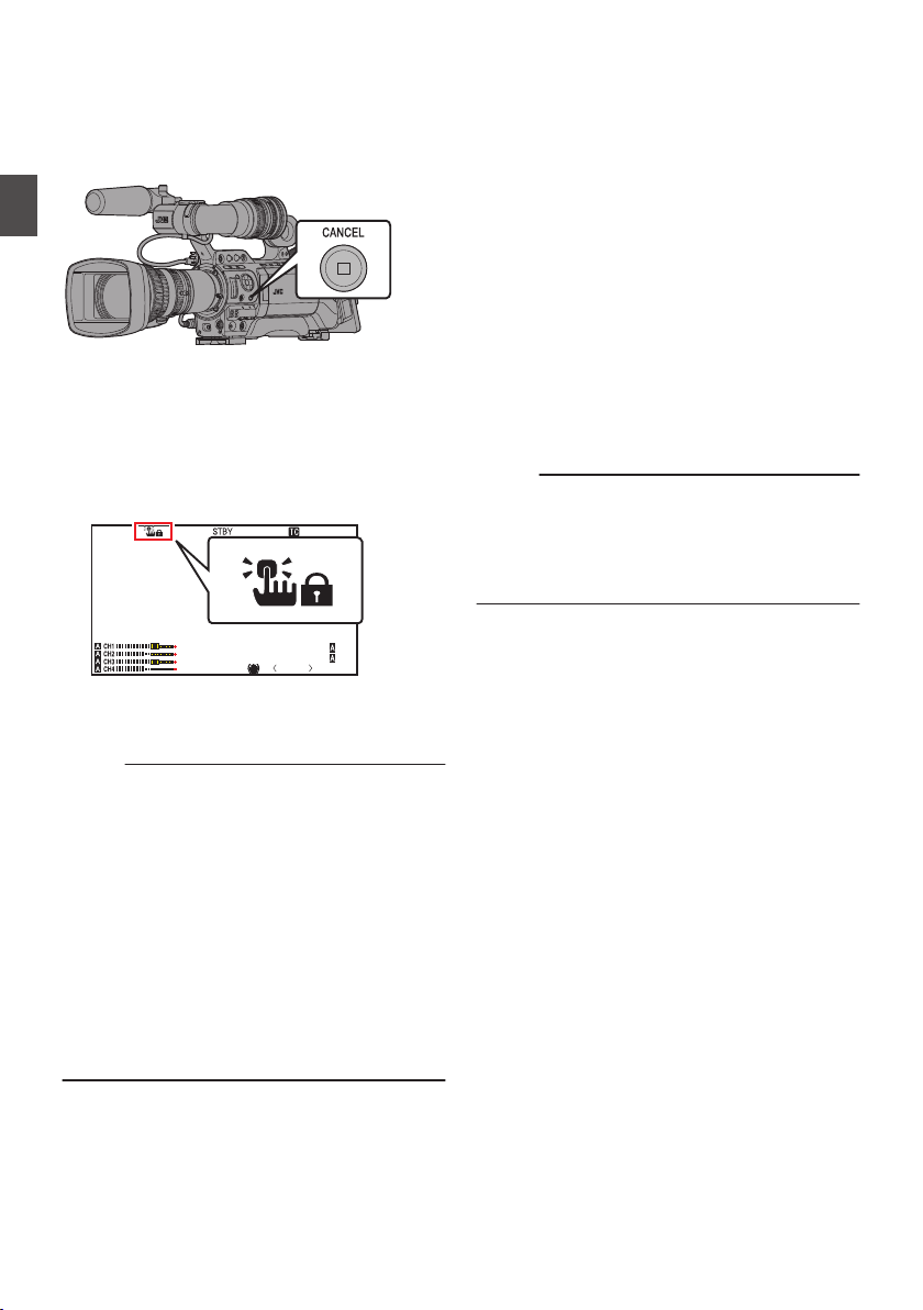
About the Operation Lock
Feature
You can use this feature to prevent erroneous
camera operation.
.
1
While in the Camera mode (when the
display screen appears), press and hold
the [CANCEL] button for 5 seconds or
longer.
0
The operation lock turns on, and an
operation lock icon (r) appears on the
display screen.
.
P13000K
1/100
F1. 6
0
dB
AE+6
ND 1 /6 4
12 :34 : 56
Jan 24,2012
00:00: 00.00
5 . 6 f t
0
Press the [CANCEL] button again for 5
seconds or longer to turn off the operation
lock.
Memo :
0
The operation lock feature is only valid in the
Camera mode.
(A P18 [Operation Modes] )
0
The power turns off and the operation lock is
disengaged.
0
The following remote operations are possible
even when the operation lock feature is turned
on.
0
Operation from the wired remote control
connected to the [REMOTE2] terminal or the
remote control unit connected to the
[REMOTE1] terminal.
0
Remote operation of the camera through
access via a web browser on devices such as
a smartphone, tablet terminal, or PC.
Operation lock does not apply to the following
buttons and switches.
0
[POWER ON/OFF] switch
0
[ND FILTER] switch
0
[AUDIO SELECT CH-1~CH-4] input selection
switch
0
[AUDIO INPUT] selection switch 1/2
0
All switches inside the LCD monitor door
0
All switches on the lens
([REC] button, [RET] button, back focus button,
[IRIS A/M] switch, [IRIS] button, grip zoom lever,
[ZOOM SERVO/MANUAL] switch, zoom ring,
iris ring, focus ring)
0
[MONITOR] adjustment knob
0
Grip zoom lever/handle zoom lever
0
[ZOOM SERVO/MANUAL] switch
0
[FIX/VAR/OFF] zoom speed switch
0
[REC/10] button (side operation panel)
0
[AWB/9] button (lens bottom)
0
[REC] button (handle top)
Memo :
0
Operation lock is not applied only when “Rec” is
assigned to the [AWB/9] button at the bottom of
the lens or the [REC/10] button on the side
operation panel in the [Camera Function] B
[User Switch Set] menu.
48
About the Operation Lock Feature
Preparations
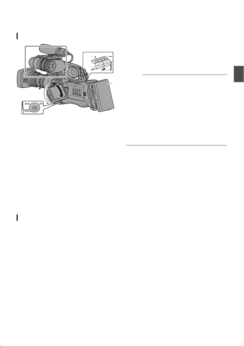
Basic Shooting
Procedures
Preparations
.
1
5
2
3
4
1
Attach the necessary accessories.
(A P28 [Settings and Adjustments Before
Use] )
2
Supply battery or AC adapter power to the
camera recorder.
(A P30 [Power Supply] )
3
Insert an SD card.
(A P43 [SD Card] )
4
Turn on the power of the camera recorder.
Setting the [POWER ON/OFF] switch to “ON”
starts up the camera recorder in the Camera
mode to enable shooting.
5
Adjust the angle of the LCD monitor and
viewfinder.
(A P38 [Adjusting the LCD Monitor and
Viewfinder] )
Shooting
1
Configure the video and audio input
settings.
You have to configure video settings such as
brightness adjustment (iris, gain, shutter) and
white balance adjustment in order to start
shooting. You also have to adjust the audio
input settings and audio recording level for
audio recording.
0
Adjusting the Brightness
(A P57 [Adjusting the Brightness] )
0
Adjusting the White Balance
(A P63 [Adjusting the White Balance] )
0
Adjusting Audio Input Settings and
Recording Level
(A P69 [Audio Recording] )
2
Press the [REC] button to start recording to
the SD card.
This camera recorder has three [REC] buttons.
Any of the [REC] buttons can be used to start/
stop recording by default.
The front and back tally lamps light up in red
during recording.
0
Zoom Operation
(A P52 [Zoom Operation] )
0
Adjusting the Focus Manually
(A P53 [Focus Operation F] )
Memo :
0
If both the slots are loaded with recordable cards
in the factory default, pressing the [REC] button
starts recording only to the media in the selected
slot.
When [Main Menu] B [System] B [Record Set]
B [Slot Mode] is set to “Dual”, recording can be
performed simultaneously to the cards in both
the slots.
(A P85 [Dual Rec] )
0
The tally lamps can be turned off in the [System]
B [Front Tally]/[Back Tally] menu.
(A P130 [Front Tally/Back Tally] )
3
Check the most recently captured images.
0
Press the user button assigned with the [Clip
Review] function to activate the Clip Review
function. The most recently captured images
are played back on the LCD monitor and
viewfinder screen.
0
After playback, the camera recorder returns
to standby mode (STBY).
(A P83 [Viewing Recorded Videos
Immediately (Clip Review)] )
Basic Shooting Procedures
49
Shooting
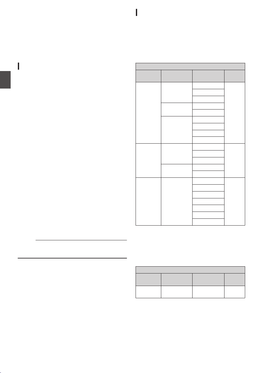
Selecting a Recording
Format
The following are steps to select the video
resolution, recording/playback file format, and
video format of videos recorded on this camera
recorder.
Selecting a Recording Format
1
Set the [System Frequency].
Select using [Main Menu] B [System] B
[System Frequency].
(A P131 [ System Frequency ] )
2
Select a recording format.
Set the following items in [Main Menu] B
[Record Format].
0
Slot A settings
0
Recording file format
(A P133 [ W Format ] )
0
Recording resolution
(A P133 [ W Resolution ] )
0
Number of recording frame/image quality
(A P133 [ W Frame & Bit Rate ] )
0
Number of recording audio channels
(A P133 [ W Audio ] )
0
Slot B settings (as needed)
(A P134 [ Y Format ] )
(A P134 [ Y Resolution ] )
(A P134 [ Y Frame & Bit Rate ] )
(A P134 [ Y Audio ] )
3
Select an aspect ratio for the SD video
recording (as needed).
Select an SD video aspect ratio when [System]
is set to “SD”, “HD+SD” or “SD(SDI In)”.
You can select “16:9” or “4:3”.
(A P135 [ SD Aspect ] )
Memo :
0
The aspect ratio is fixed at “16:9” when [System]
is set to “HD”“HD+Web” or “HD(SDI In)”.
4
After setting is complete for all items, press
the [OIS/1] button.
0
Switches the recording format.
0
A “Please Wait...” message appears on the
screen during switching.
Possible Slot A Setting Combinations
When [System] B [System Frequency] is set to
“60/30/24”
0
When [Record Format] B [System] is set to HD,
“HD+SD”, “HD+Web”, “HD(SDI In)” (U model)
0
When [Record Format] B [System] is set to HD,
“HD+Web”, “HD(SDI In)” (E model)
Record Format
W Format W Resolution W Frame &
Bit Rate
W Audio
QuickTime
MP4
MXF *1
(MPEG2)
1920x1080 60i (HQ) 4ch/
2ch
30p (HQ) *2
24p (HQ) *2
1440x1080 60i (HQ)
60i (SP)
1280x720 60p (HQ)
30p (HQ) *2
24p (HQ) *2
60p (SP)
AVCHD 1920x1080 60p (HQ) *2 2ch
60i (HQ)
60i (SP)
1440x1080 60i (LP)
60i (EP)
QuickTime
(H.264)
1920x1080 60p (XHQ) *2 4ch/
2ch
60i (XHQ)
30p (XHQ) *2
24p (XHQ) *2
60i (UHQ)
30p (UHQ) *2
24p (UHQ) *2
*1 The “1280x720” setting is not available for
MXF files.
*2 Not selectable in the “HD(SDI In)” setting.
0
When [Record Format] B [System] is set to
“SD”, “SD(SDI In)” (U model)
Record Format
W Format W Resolution W Frame &
Bit Rate
W Audio
QuickTime
(H.264)
720x480 60i 4ch/
2ch
50
Selecting a Recording Format
Shooting
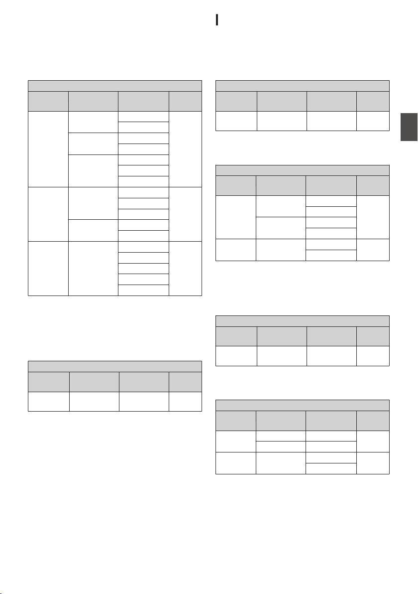
When [System] B [System Frequency] is set to
“50/25”
0
When [Record Format] B [System] is set to HD,
“HD+Web”, “HD(SDI In)” (U model)
0
When [Record Format] B [System] is set to HD,
“HD+SD”, “HD+Web”, “HD(SDI In)” (E model)
Record Format
W Format W Resolution W Frame &
Bit Rate
W Audio
QuickTime
MP4
MXF *1
(MPEG2)
1920x1080 50i (HQ) 4ch/
2ch
25p (HQ) *2
1440x1080 50i (HQ)
50i (SP)
1280x720 50p (HQ)
25p (HQ) *2
50p (SP)
AVCHD 1920x1080 50p (HQ) *2 2ch
50i (HQ)
50i (SP)
1440x1080 50i (LP)
50i (EP)
QuickTime
(H.264)
1920x1080 50p (XHQ) *2 4ch/
2ch
50i (XHQ)
25p (XHQ) *2
50i (UHQ)
25p (UHQ) *2
*1 The “1280x720” setting is not available for
MXF files.
*2 Not selectable in the “HD(SDI In)” setting.
0
When [Record Format] B [System] is set to
“SD”, “SD(SDI In)” (E model)
Record Format
W Format W Resolution W Frame &
Bit Rate
W Audio
QuickTime
(H.264)
720x576 50i 4ch/
2ch
Possible Slot B Setting Combinations
When [System] B [System Frequency] is set to
“60/30/24”
0
When [Record Format] B [System] is set to “HD
+SD” (U model)
Record Format
Y Format Y Resolution Y Frame &
Bit Rate
Y Audio
QuickTime
(H.264)
720x480 60i 4ch/
2ch
0
When [Record Format] B [System] is set to “HD
+Web”
Record Format
Y Format Y Resolution Y Frame &
Bit Rate
Y Audio
QuickTime
(H.264)
480x270 30p (LP) 4ch/
2ch
24p (LP)
960x540 30p (HQ)
24p (HQ)
AVCHD 1440x1080 60i (LP) 2ch
60i (EP)
When [System] B [System Frequency] is set to
“50/25”
0
When [Record Format] B [System] is set to “HD
+SD” (E model)
Record Format
Y Format Y Resolution Y Frame &
Bit Rate
Y Audio
QuickTime
(H.264)
720x576 50i 4ch/
2ch
0
When [Record Format] B [System] is set to “HD
+Web”
Record Format
Y Format Y Resolution Y Frame &
Bit Rate
Y Audio
QuickTime
(H.264)
480x270 25p (LP) 4ch/
2ch
960x540 25p (HQ)
AVCHD 1440x1080 50i (LP) 2ch
50i (EP)
Selecting a Recording Format
51
Shooting
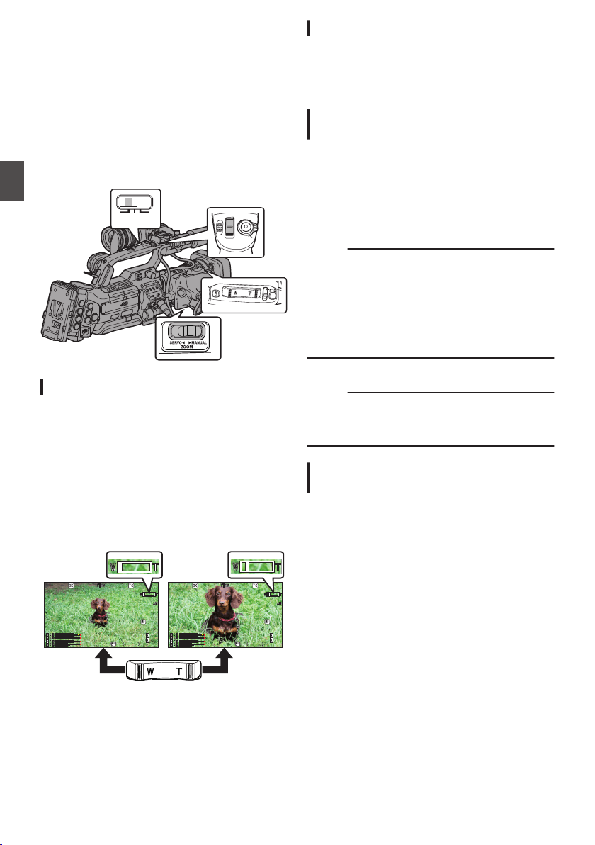
Zoom Operation
Adjusts the angle of view.
Zoom ratio: 1x to 20x (optical zoom only)
Zooming can be operated using any of the three
levers/rings below.
0
Zoom Lever at the Grip
0
Zoom Lever at the Handle F
0
Zoom Ring at the Lens Section:
Functions as a zoom ring when the [ZOOM
SERVO/MANUAL] switch is set to “MANUAL”.
.
FIX VAR OFF
W
T
REC
HOLD
Using the Zoom Lever at the Grip
1
Set the [ZOOM SERVO/MANUAL] switch to
“SERVO”.
2
Press the zoom lever to zoom.
0
The zoom speed changes according to the
extent the zoom lever is being pushed.
0
Zooms into wide angle and increases the
angle of view when “W” is pressed.
0
Zooms into telephoto and decreases the
angle of view when “T” is pressed.
0
A zoom bar appears during zoom operation
.
12 .5/ 30 f
ps
ps
P 13000K
P 13000K
1/100
1/100
F1.6
F1.6
0dB
0dB
AE+6
AE+6
ND 1/64
ND 1/64
12:34:56
12:34:56
Jan 24,2014
Jan 24,2014
00:00:00.00
00:00:00.00
5.
5.6 f t
12 .5/ 30 f
ps
ps
P 13000K
P 13000K
1/100
1/100
F1.6
F1.6
0dB
0dB
AE+6
AE+6
ND 1/64
ND 1/64
12:34:56
12:34:56
Jan 24,2014
Jan 24,2014
00:00:00.00
00:00:00.00
5.
5.6 f t
Using Zoom Ring at the Lens Section
1
Set the [ZOOM SERVO/MANUAL] switch to
“MANUAL”.
You can adjust the preferred angle of view by
turning the zoom ring.
Using the Zoom Lever at the Handle
F
The handle zoom lever operates only when the
supplied lens is in use.
1
Set the [ZOOM SERVO/MANUAL] switch to
“SERVO”.
2
Set the [FIX/VAR/OFF] zoom speed switch
to “FIX” or “VAR”.
Memo :
0
Setting to “FIX” will allow the zoom operation to
move at the speed set in [Handle Zoom Speed].
0
Set the zoom speed using [Main Menu] B
[Camera Function] B [Handle Zoom Speed].
(A P110 [ Handle Zoom Speed F ] )
0
Setting to “VAR” will change the zoom speed
according to the pressure applied on the lever.
3
Press the zoom lever at the handle to zoom.
Memo :
0
When the [FIX/VAR/OFF] zoom speed switch is
set to “OFF”, the zoom lever at the handle
section cannot be used.
Saving/Recalling Current Zoom
Position (Preset Zoom) F
The handle zoom lever operates only when the
supplied lens is in use.
This allows you to register up to three zoom
positions.
52
Zoom Operation
Shooting
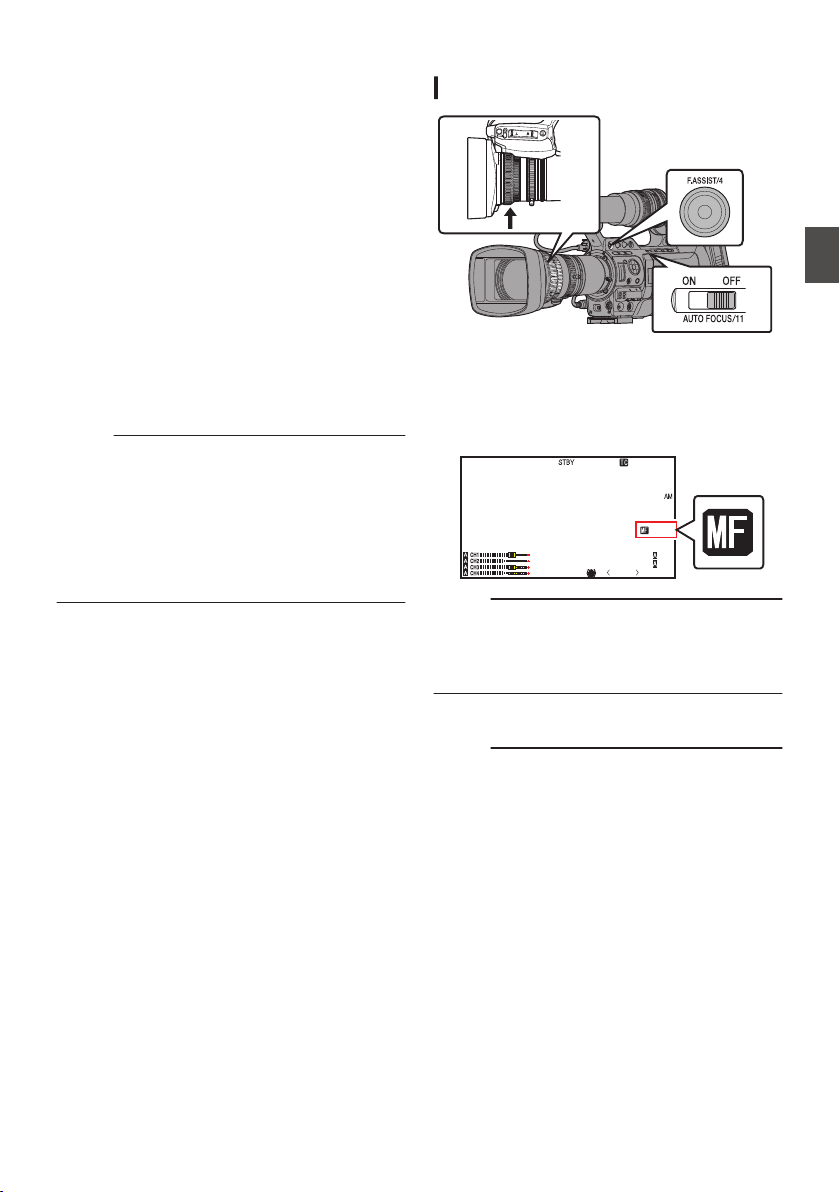
1
Assign the “Preset Zoom1”, “Preset
Zoom2”, or “Preset Zoom3” function to any
of the user buttons.
* This excludes the [AUTO FOCUS/11] button.
(A P42 [Assignment of Functions to User
Buttons] )
(A P111 [USER1 to USER11, Lens RET] )
2
Save the current zoom position.
0
Press any of the buttons assigned with the
“Preset Zoom1”, “Preset Zoom2”, or “Preset
Zoom3” function for more than 1 second.
0
The current zoom position will be stored.
3
Recall the stored zoom position.
0
Press any of the buttons assigned with the
“Preset Zoom1”, “Preset Zoom2”, or “Preset
Zoom3” function and release within 1
second.
0
The camera recorder zooms to the stored
zoom position.
Memo :
0
To recall the stored zoom position, set the
[ZOOM SERVO/MANUAL] switch to “SERVO”.
0
The zoom speed to the zoom position can be set
with [Main Menu] B [Camera Function] B
[Preset Zoom Speed].
(A P112 [ Preset Zoom Speed F ] )
0
Operating other zoom maneuvers during a
zoom position recall will cancel the recall.
Focus Operation F
Adjusting Focus Manually
.
1
Set the [AUTO FOCUS/11] switch to “OFF”.
The manual focus icon d appears on the
screen.
The handle zoom lever operates only when the
supplied lens is in use.
.
P13000K
1/100
F1. 6
0dB
AE+6
ND 1 /64
12 : 34 : 56
Jan 24 , 2014
00: 00:00.00
5 . 6 f t
Memo :
0
If [Main Menu] B [LCD/VF] B [Display
Settings] B [Focus] is set to “Off”, the d icon will
not appear.
(A P122 [ Focus F ] )
2
Turn the focus ring to adjust the focus.
Memo :
0
Using the Focus Assist or Expanded Focus
function makes it easier to focus.
(A P55 [Focus Assist Function] )
(A P55 [Expanded Focus Function] )
0
Even while in the Manual Focus mode, pressing
the [RET] button on the lens or the user button
assigned with the “One Push Focus” function
switches the camera recorder to the One-push
Autofocus mode.
Zoom Operation
53
Shooting
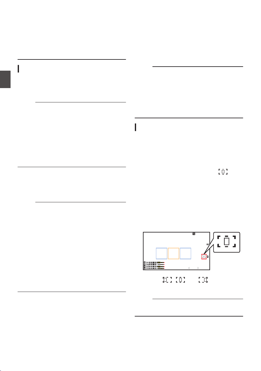
0
Even while in the Manual Focus mode, pressing
and holding the [RET] button on the lens or the
user button assigned with the “One Push
Focus” function switches the camera recorder to
the Push Autofocus mode.
(A P54 [One Push Auto Focus] )
(A P54 [Setting to Auto Focus Temporarily
(Push Auto Focus)] )
Adjusting Focus Automatically F
The handle zoom lever operates only when the
supplied lens is in use.
Set the [AUTO FOCUS/11] switch to “ON”.
The auto focus icon e appears on the screen.
Memo :
0
If [Main Menu] B [Camera Function] B [AF
Assist] is set to “Area” or “Far/Near”, you can turn
the focus ring to shift the auto focus point while
in the automatic focus adjustment mode.
(A P54 [AF Assist Function F] )
(A P110 [ AF Assist F ] )
0
If [Main Menu] B [LCD/VF] B [Display
Settings] B [Focus] is set to “Off”, the auto focus
icon will not appear.
(A P122 [ Focus F ] )
One Push Auto Focus
While in the Manual Focus mode, pressing the
[RET] button on the lens (less than 1 second) sets
the focus at the center of the frame automatically.
Memo :
0
Face detection does not work during One Push
Auto Focus.
0
AF Assist does not function.
0
When the operation is complete, the camera
recorder returns to the Manual Focus mode
automatically.
0
One Push Auto Focus functions with emphasis
on the focusing speed. This function is not
suitable during recording.
0
“One Push Focus” is assigned to the [RET]
button on the lens in the factory default setting.
0
“One Push Focus” can also be assigned to other
user buttons.
(A P42 [Assignment of Functions to User
Buttons] )
Setting to Auto Focus Temporarily
(Push Auto Focus)
0
In the Manual Focus mode, the camera recorder
switches temporarily to the Autofocus mode and
automatically adjusts the focus when you take a
shot with the [RET] button on the lens pressed
down.
0
Release the [RET] button to return to the Manual
Focus mode.
Memo :
0
Face detection does not work during Push Auto
Focus.
0
“One Push Focus” is assigned to the [RET]
button on the lens in the factory default setting.
0
“One Push Focus” can also be assigned to other
user buttons.
(A P42 [Assignment of Functions to User
Buttons] )
AF Assist Function F
To shift the auto focus point during Auto Focus
(AF), you can turn the focus ring to set the point to
the left, center, right, or near and far directions.
0
Set [Main Menu] B [Camera Function] B [AF
Assist].
0
Area:
Selecting this option displays the
icon in
the area.
Turning the focus ring during AF displays the
focus area on the left, center, and right side
for about 2 seconds. Turning the focus ring
within 2 seconds allows you to move the
orange frame to select the focus area.
After selecting the area, focus is
automatically adjusted to a focus point near
the selected area.
.
----
B5600K
1/100
F9. 0
12
dB
12 :34 :56
Jan 24 , 2014
00: 00:00.00
* The icons ( , , and ) change in
conjunction with the orange frame in the focus
area.
Memo :
0
When [Face Detect] is set, “Area” is not
selectable.
54
Focus Operation F
Shooting
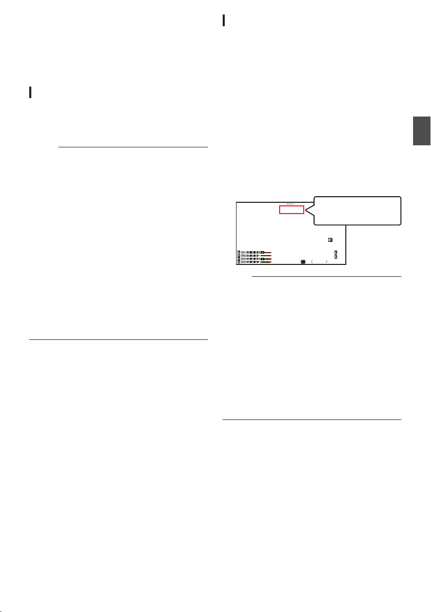
0
Far/Near:
This option allows you to shift the auto focus
point to near and far directions by turning the
focus ring during AF.
Focus is automatically adjusted to a focus
point near the position where the focus ring
stops turning.
Focus Assist Function
0
When the [F.ASSIST/4] button is pressed during
shooting, the focused area is displayed in color.
This enables easy and accurate focusing.
0
Select the color (blue, red or green) in the menu.
Memo :
0
When [Main Menu] B [LCD/VF] B [Shooting
Assist] B [Focus Assist] B [Type] is set to
“ACCU-Focus”, the depth of field becomes
shallower to enable easier focusing.
(A P121 [ Focus Assist ] )
0
The “ACCU-Focus” function switches
automatically to “Off” after about 10 seconds.
0
Select the display color in [Main Menu] B [LCD/
VF] B [Shooting Assist] B [Focus Assist] B
[Color].
(A P121 [ Color ] )
0
If you use the zebra function and the Focus
Assist function at the same time, it may be
difficult to see the effect of the Focus Assist. In
this case, turn off the zebra function.
(A P79 [Setting Zebra Pattern] )
0
During Focus Assist operation, the contour
correction effect on the viewfinder/LCD monitor
will be temporarily disabled.
Setting Focus Assist Function to a User Button
You can assign the “Focus Assist” function to a user
button.
(A P42 [Assignment of Functions to User
Buttons] )
Expanded Focus Function
Magnifies the image at the center. Doing so
enables precise focus to be established easily.
1
Assign the “Expanded Focus” function to
any of the user buttons.
* This excludes the [AUTO FOCUS/11] button.
(A P42 [Assignment of Functions to User
Buttons] )
(A P111 [USER1 to USER11, Lens RET] )
2
Press the user button that is assigned with
the “Expanded Focus” function.
0
[EXPANDED] (yellow color) appears on the
screen, and the center part of the image is
enlarged.
0
Pressing the user button again restores the
image to the original size.
.
P13000K
1/100
F1. 6
0
dB
AE+6
ND 1 /64
12 : 34 :56
Jan 24 , 2014
00: 00:00.00
5 . 6 f t
EXPANDED
EXPANDED
EXPANDED
EXPANDED
Memo :
0
To set the operation when the button is pressed,
go to [Main Menu] B [Camera Function] B [User
Switch Set] B [Expanded Focus].
(A P112 [ Expanded Focus ] )
0
This function can be used together with the
Focus Assist function.
0
The magnification ratio varies with the format of
the record signals.
0
Magnifying an image does not alter the size of
the recorded image.
0
This function is unavailable when [Main Menu]
B [System] B [Record Set] B [Record Format]
B [System] is set to “SD”, “HD(SDI In)”, or
“SD(SDI In)”.
Focus Operation F
55
Shooting
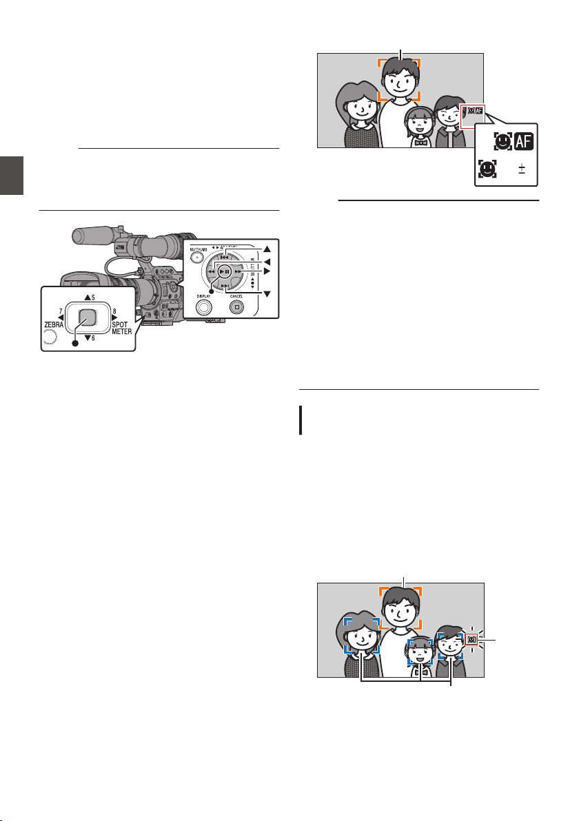
Adjusting the Focus by
Face Detection F
This function detects human faces and
automatically adjusts focus during Auto Focus.
It can also track moving objects.
When several faces are detected, you can select
one to focus on.
Memo :
0
This function can also adjust the brightness
automatically according to the brightness of the
face detected.
(A P112 [ Face Detect F ] )
.
1
Assign the “Face Detect” function to any of
the user buttons.
* This excludes the [AUTO FOCUS/11] button.
(A P42 [Assignment of Functions to User
Buttons] )
2
Focus the camera recorder on a person and
press the user button that is assigned with
“Face Detect”.
0
When Face detection is enabled, the face
detection icon (q) appears.
0
When [Main Menu] B [Camera Function]
B [User Switch Set] B [Face Detect] is set
to “AF”, “q e” appears.
0
When [Main Menu] B [Camera Function]
B [User Switch Set] B [Face Detect] is set
to “AF&AE”, “q AE±0” appears.
0
If you select the person nearest to the center
of the screen, an orange frame will appear
on his face.
0
Focus will be automatically adjusted for the
selected person.
.
Detection Frame (Orange)
AE
Memo :
0
If the detection frame does not appear, make
sure that the [AUTO FOCUS/11] switch is set to
“ON”. Also, if [Face Detect] is set to “AF&AE”,
set at least one of the iris, gain, and electronic
shutter control items to the automatic
adjustment mode.
(A P57 [Adjusting the Brightness
Automatically] )
(A P58 [Auto Iris (Automatic Adjustment)
Mode] )
(A P59 [Automatic Gain Mode (Automatic
Gain Adjustment)] )
(A P62 [Automatic Shutter Mode (Automatic
Shutter Adjustment)] )
Selecting Specific Person from Several
Persons
1
Hold down the user button that is assigned
with “Face Detect”.
0
The camera recorder will enter face
selection mode and the face detection icon
(q) will blink.
0
An orange frame will appear on the face of
the person nearest to the center of the
screen. Blue frames will appear on the faces
of others.
.
Detection Frame (Blue)
Detection Frame (Orange)
Blinking
56
Adjusting the Focus by Face Detection F
Shooting
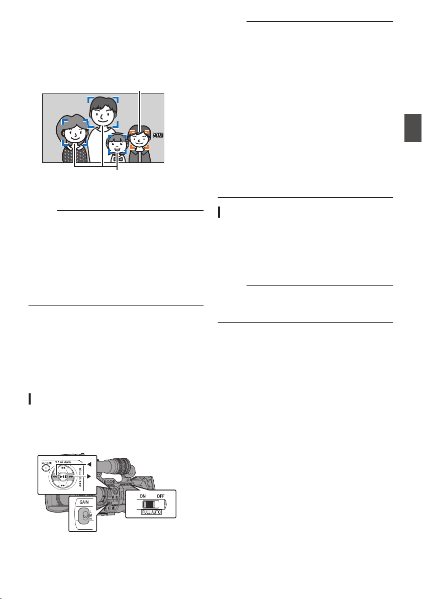
2
Select a specific portrait subject.
0
Use the cross-shaped button (HIJK) to
select a person.
0
An orange frame will appear on the face of
the selected person and focus will be
automatically adjusted.
.
Detection Frame (Blue)
Detection Frame (Orange)
3
Press the Set button (
R) to confirm the
person for face detection.
Memo :
0
Press the [CANCEL] button to cancel the
selection.
0
You can specify the detection sensitivity and the
operation speed after losing sight of the face
using [Main Menu] B [Camera Function] B
[User Switch Set] B [Face Detect] B [Sensitivity]
and [Hysteresis].
(A P112 [ Sensitivity ] )
(A P112 [ Hysteresis ] )
Adjusting the Brightness
Adjust the brightness using Iris, Gain, Shutter
speed and ND filter according to the brightness of
the object.
Adjusting the Brightness Automatically
When the [FULL AUTO] switch is set to “ON”, Iris,
Gain, Shutter speed and ND filter are automatically
adjusted according to the brightness of the object
to maintain optimum brightness.
.
Memo :
0
You can use the cross-shaped button (HI) on
the side of the camera recorder to set the target
level (brighter/darker) to maintain optimum
brightness during automatic adjustment.
(A P109 [ AE Level ] )
0
The convergence speed of the automatic
adjustment for gain, shutter and iris can be set
in the menu.
(A P109 [ AE Speed ] )
0
If one or more of the items (Gain, Iris and
Shutter) have been set to “Auto”, the value of the
corresponding items when the user button that
is assigned “AE Lock” is pressed can be fixed.
(A P112 [ AE Lock ] )
0
The brightness varies depending on the various
settings of the [FULL AUTO] item in the [Camera
Function] menu.
(A P113 [FULL AUTO Item] )
Adjusting the Brightness Manually
When the [FULL AUTO] switch is set to “OFF”,
some or all of the items (Iris, Gain and Shutter
Speed) can be manually adjusted.
(A P58 [Adjusting the Iris] )
(A P59 [Setting the Gain] )
(A P60 [Setting the Electronic Shutter] )
Memo :
0
If Iris, Gain and Shutter Speed are manually
adjusted, the [AE Level] setting is temporarily
disabled.
Adjusting the Focus by Face Detection F
57
Shooting
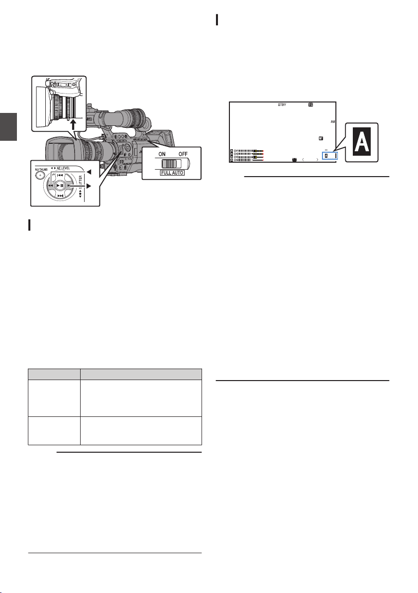
Adjusting the Iris
You can adjust the aperture of the lens iris manually
or automatically according to the brightness of the
object.
.
Manual Iris (Manual Adjustment) Mode
The aperture value (F-number) of the lens can be
set manually.
1
Set the [IRIS A/M] mode selection switch on
the lens to “M”.
The camera recorder switches to the Manual
Iris mode, and the a icon on the screen
disappears.
2
Turn the iris ring on the lens to adjust the
iris manually.
The open F-number of the supplied lens varies with
the zoom position. F
Wide [W] end : F1.6
Tele [T] end : F3.0
F-number Description
Decrease The subject appears brighter.
The focused range becomes
sharper, while the background is
blurred to produce a soft image.
Increase The subject appears darker.
Background of image becomes
focused as well.
Memo :
0
Even while in the Manual Focus mode, pressing
the [IRIS] button on the lens or the user button
assigned with the [One Push Iris] function
switches the camera recorder to the One-push
Auto Iris mode.
0
Even while in the Manual Focus mode, pressing
and holding the [IRIS] button on the lens or the
user button assigned with the [One Push Iris]
function switches the camera recorder to the
Push Auto Iris mode.
Auto Iris (Automatic Adjustment) Mode
The iris is automatically adjusted according to the
brightness of the object.
1
Set the [IRIS A/M] mode selection switch on
the lens to “A”.
The camera recorder switches to the Auto Iris
mode, and the a icon appears on the screen.
.
P13000K
1/100
F1. 6
0dB
AE+6
ND 1/64
12 :34 :56
Jan 24 , 2014
00: 00:00.00
5 . 6 f t
Memo :
0
Set the [FULL AUTO] switch on the camera
recorder to “ON” to enter Auto Iris mode
(automatic adjustment mode). The iris is
automatically adjusted according to the
brightness of the object.
In this case, operation of the [IRIS A/M] mode
selection switch and [IRIS] button on the lens is
disabled.
0
The iris open/close limit can be set in [Main
Menu] B [Camera Function] B [Auto Iris Limit
(OPEN)]/[Auto Iris Limit (CLOSE)] during Auto
Iris.
(A P109 [ Auto Iris Limit (OPEN) ] )
(A P109 [ Auto Iris Limit (CLOSE) ] )
0
You can use the cross-shaped button (HI) on
the side control panel to set the target level
(brighter/darker) of the auto iris.
(A P109 [ AE Level ] )
0
The convergence speed of the auto iris can be
set in the menu.
(A P109 [ AE Speed ] )
58
Adjusting the Iris
Shooting
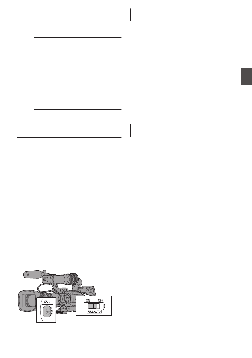
One Push Auto Iris F
When the camera recorder is in the Manual Iris
mode, press the [IRIS] button on the lens to adjust
the iris according to the brightness of the subject.
Memo :
0
“One Push Iris” can also be assigned to other
user buttons.
(A P42 [Assignment of Functions to User
Buttons] )
Push Auto Iris
When the camera recorder is in the Manual Iris
mode, press and hold the [IRIS] button on the lens
to change to the Auto Iris mode temporarily. The
iris will be automatically adjusted according to the
brightness of the subject.
Memo :
0
“One Push Iris” can also be assigned to other
user buttons.
(A P42 [Assignment of Functions to User
Buttons] )
About the Iris F-number
Blurry effects due to “small aperture diffraction”
may occur when the diameter of the iris becomes
too small. When this phenomenon occurs, the F-
number on the screen turns gray to warn you that
the diffraction F-number of the iris has been
exceeded.
You are recommended to make appropriate use of
ND filters to prevent the F-number from turning
gray.
Setting the Gain
This function electrically boosts the light sensitivity
when there is insufficient illumination on the object.
You can set the gain of the video amplifier
according to the brightness of the object. Select the
setting mode according to your shooting
conditions.
.
Manual Gain Mode (Manual Gain
Switching)
0
Select the gain level of the video amplifier using
the [GAIN L/M/H] selection switch on the
camera recorder.
0
The a icon on the screen disappears.
0
The default positions of the switch are as
follows.
[L] : 0dB
[M] : 6dB
[H] : 12dB
Memo :
0
You can change the gain value of each position
in the menu. Increasing the sensitivity causes
the screen to appear grainier.
0
The camera recorder switches to the Auto Gain
mode when the gain value is set to “ALC”.
(A P109 [GAIN L/GAIN M/GAIN H] )
Automatic Gain Mode (Automatic Gain
Adjustment)
1
Set the [FULL AUTO] switch to “ON”.
0
The camera recorder switches to the Auto
Gain Adjustment mode (fixed at “ALC”), and
the gain of the video amplifier is
automatically set according to the brightness
of the subject.
In this case, the [GAIN L/M/H] selection
switch on the camera recorder is disabled.
0
The a icon appears on the screen.
Memo :
0
The upper limit of the gain setting value during
ALC operation can be set in [Main Menu] B
[Camera Function] B [ALC Limit].
(A P109 [ ALC Limit ] )
0
When [Camera Function] B [FULL AUTO] B
[Gain] is set to “SW Set”, the gain value can be
altered using the [GAIN L/M/H] selection switch
even when the [FULL AUTO] switch on the
camera body is set to “ON”.
(A P113 [ Gain ] )
0
You can switch to the Auto Gain mode by setting
the items in [Camera Function] B [GAIN L],
[GAIN M], and [GAIN H] to “ALC”.
(A P109 [GAIN L/GAIN M/GAIN H] )
Adjusting the Iris
59
Shooting
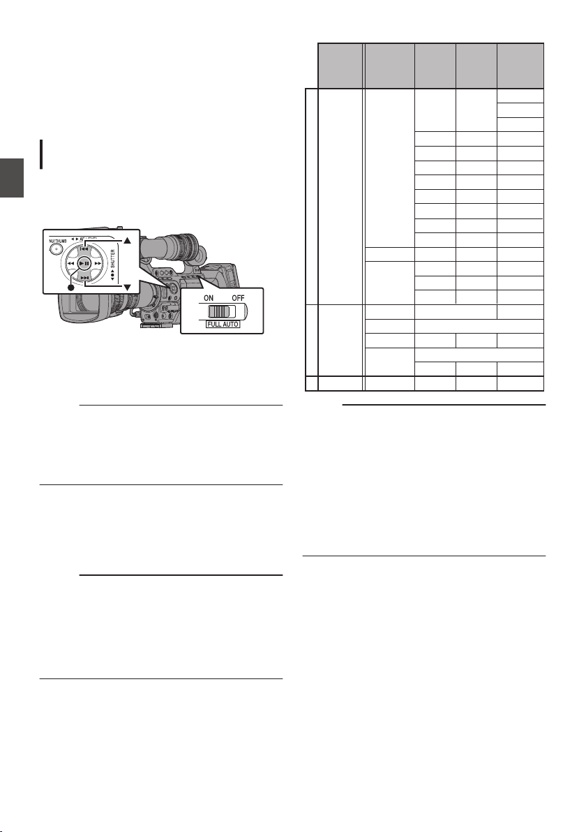
Setting the Electronic
Shutter
You can change the shutter speed (time for each
shooting frame) using the electronic shutter
function. Electronic shutter can be adjusted
manually or automatically.
Manual Shutter Mode (Manual Shutter
Switching)
Use the Set button (R) to switch between the
shutter modes and the cross-shaped button (JK)
to switch between the speeds.
.
Switching Shutter Mode
Press the Set button (center of the cross-shaped
button) to turn ON/OFF the shutter.
Memo :
0
When the shutter is ON, “Step”, “Variable”, or
“EEI” may be selected using [Camera
Function] B [Shutter] menu. “Step” is the factory
default.
(A P108 [ Shutter ] )
Switching Shutter Speed
When shutter is ON, use the cross-shaped button
(JK) to set the shutter speed. Shutter speed differs
according to the video format and variable frame
rate settings.
Memo :
0
To display Shutter in angle (DEG), set [WFrame
& Bit Rate] to 25p(XHQ), 25p(UHQ), 25p(HQ),
24p(XHQ), 24p(UHQ), or 24p(HQ), and set
[Shutter] in [LCD/VF] B [Display Settings] to
“DEG”.
(A P133 [ W Frame & Bit Rate ] )
(A P124 [ Shutter ] )
During Modes Other Than Variable Frame Rec
.
720/60p
720/30p
1080/60i
1080/30p
720/50p
720/25p
1080/50i
1080/25p
720/24p
1080/24p
J ON
^^
1/10000
1/4000
1/2000
1/1000
1/500
1/250
1/500 1/500
1/120
1/100
1/120
1/60
1/100
1/100 1/50
1/60 1/50 1/48
1/30 1/25 1/24
1/15 1/12.5 1/12
K
1/7.5 1/6.25 1/6
J ON
~
1/60.00
~
K
1/30.07 1/25.05 1/24.05
OFF 1/60 1/50 1/48
1/10227
1/10843
1/54
1/10000 1/10000
1/250 1/250
1/120
1/1000 1/1000
1/2000 1/2000
1/4000 1/4000
1080/60p 1080/50p
1/48.00
1/50.00
(Lower limit)
Default values
(Upper limit)
(Standard)
(Variable)
(Step)
Resolution/
Frame Rate
Shutter
Memo :
0
The operations of the cross-shaped button
(JK) and Set button (R) are disabled in the
following cases.
0
During clip preview
0
During display of the USB switching
confirmation screen
0
During display of the formatting confirmation
screen
0
When selecting a face using face detection
0
When selecting a photometry area with [Spot
Meter] set to “Manual”
60
Setting the Electronic Shutter
Shooting
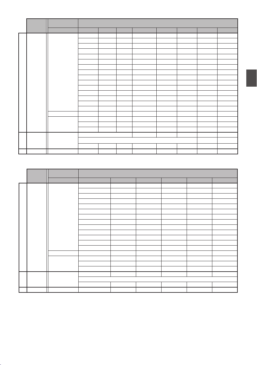
During Variable Frame Rec
.
720/30p, 720/24p, 1080/30p, 1080/24p
60, 30, 15 54, 27 50, 25 48, 24, 12, 6 45, 22.5 40, 20, 10 36, 18 32, 2
J
ON
^^^ ^ ^ ^ ^
1/10000
^^^ ^ ^ ^
1/10000 1/4000
^^^ ^ ^
1/10000 1/4000 1/2000
^^^ ^
1/10000 1/4000 1/2000 1/1000
^^^
1/10000 1/4000 1/2000 1/1000 1/500
^^
1/10000 1/4000 1/2000 1/1000 1/500 1/250
^
1/10000 1/4000 1/2000 1/1000 1/500 1/250
1/120
1/10000 1/4000 1/2000 1/1000 1/500 1/250
1/120
1/100
1/4000 1/2000 1/1000 1/500 1/250
1/120
1/100 1/60
1/2000 1/1000 1/500 1/250
1/120
1/100 1/60 1/54
1/1000 1/500 1/250
1/120
1/100 1/60 1/54 1/50
1/500 1/250
1/120
1/100 1/60 1/54 1/50 1/48
1/250
1/120
1/100 1/60 1/54 1/50 1/48 1/45
1/120
1/100 1/60 1/54 1/50 1/48 1/45 1/40
1/100 1/60 1/54 1/50 1/48 1/45 1/40 1/36
1/60 1/54 1/50 1/48 1/45 1/40 1/36 1/32
1/30 1/27 1/25 1/24 1/22.5 1/20 1/18 1/16
K
1/15 1/13.5 1/12.5 1/12 1/11.25 1/10 1/9 1/8
1/7.5 1/6.75 1/6.25 1/6 1/5.625 1/5 1/4.5 1/4
J ON
1/10227
1/10843
1/10227
1/10843
1/10227
1/10843
~
K
1/60.00 1/54.00 1/50.00 1/48.00 1/45.00 1/40.00 1/36.00 1/32.00
23/163/104/154/184/105/145/106/1FFO
(Lower limit)
(Upper limit)
(Standard)
(Variable)
(Step)
Resolution/Frame
Rate
Shutter
Frame rate
.
1080/25p
720/25p
50, 25, 12.5 48, 24, 6 45, 22.5 40, 20, 10 36, 18 32, 2
J
ON
^^^^^
1/10000
^^^^
1/10000 1/4000
^^^
1/10000 1/4000 1/2000
^^
1/10000 1/4000 1/2000 1/1000
^
1/10000 1/4000 1/2000 1/1000 1/500
1/10000 1/4000 1/2000 1/1000 1/500 1/250
1/4000 1/2000 1/1000 1/500 1/250
1/120
1/2000 1/1000 1/500 1/250
1/120
1/100
1/1000 1/500 1/250
1/120
1/100 1/50
1/500 1/250
1/120
1/100 1/50 1/48
1/250
1/120
1/100 1/50 1/48 1/45
1/120
1/100 1/50 1/48 1/45 1/40
1/100 1/50 1/48 1/45 1/40 1/36
1/50 1/48 1/45 1/40 1/36 1/32
1/25 1/24 1/22.5 1/20 1/18 1/16
K
1/12.5 1/12 1/11.25 1/10 1/9 1/8
1/6.25 1/6 1/5.625 1/5 1/4.5 1/4
J
ON
1/10227
1/10843
1/10227
1/10843
1/10227
1/10843
~
K
1/50.00 1/48.00 1/45.00 1/40.00 1/36.00 1/32.00
23/163/104/154/184/105/1FFO
(Lower limit)
(Upper limit)
(Standard)
(Variable)
(Step)
Resolution/Frame
Rate
Shutter
Frame rate
Setting the Electronic Shutter
61
Shooting
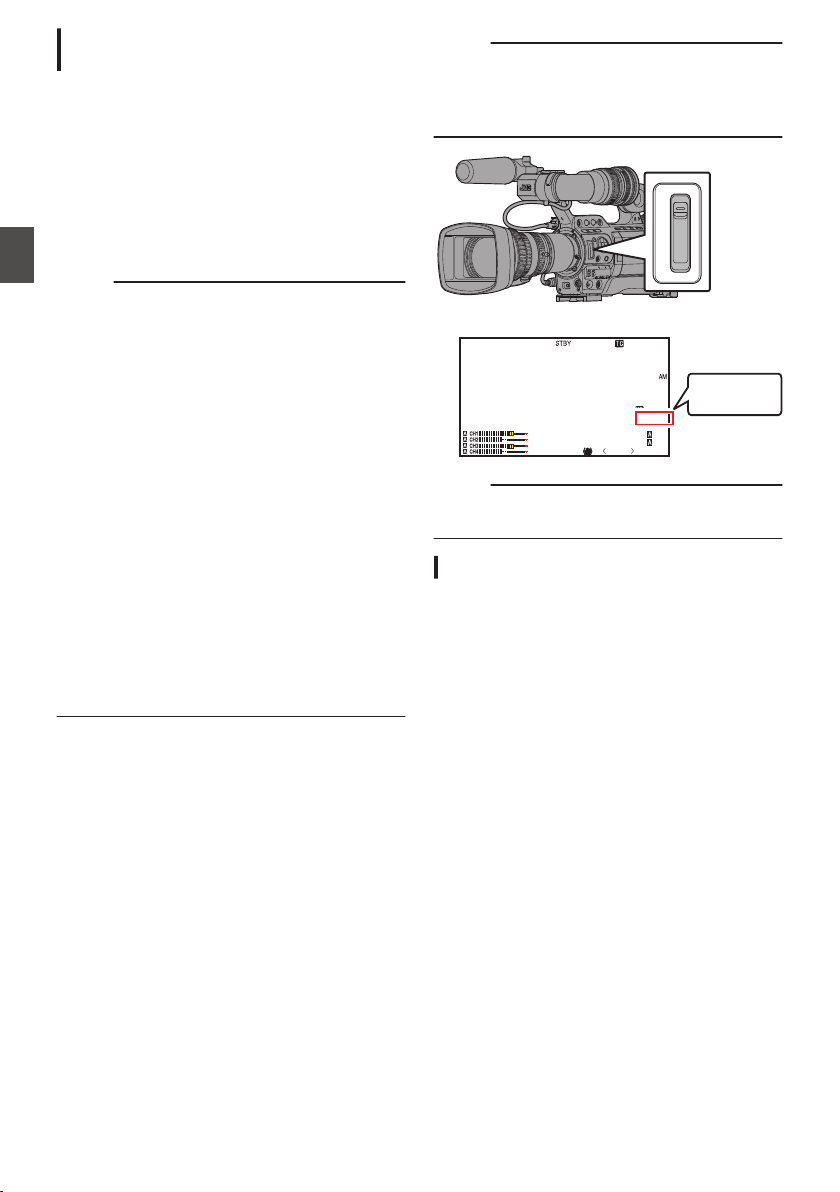
Automatic Shutter Mode (Automatic
Shutter Adjustment)
1
Set the [FULL AUTO] switch to “ON” to set
to the Auto Shutter mode.
0
The a icon appears on the screen.
0
The camera recorder enters the Auto Shutter
mode. The shutter speed is automatically
adjusted according to the brightness of the
subject.
Switching of shutter speed with the cross-
shaped button (JK) and switching of shutter
mode with the Set button (R) are disabled.
Memo :
0
You can set the controllable range for the
Automatic Shutter in [Main Menu] B [Camera
Function] B [EEI Limit].
(A P109 [ EEI Limit ] )
0
When [Camera Function] B [FULL AUTO] B
[Shutter] is set to “SW Set”, the shutter mode can
be adjusted using the Set button (R), and the
shutter speed can be altered using the cross-
shaped buttons (JK) even when the [FULL
AUTO] switch on the camera body is set to
“ON”.
0
Setting [Camera Function] B [FULL AUTO] B
[Shutter] to “EEI” switches the camera recorder
to the Automatic Shutter Adjustment mode. In
this case, adjustment of the shutter mode using
the Set button (R), and adjustment of the shutter
speed with the cross-shaped buttons (JK) will
be disabled.
(A P113 [ Shutter ] )
0
You can also switch to the Auto Shutter mode by
setting [Camera Function] B [Shutter] to “EEI”.
(A P108 [ Shutter ] )
Setting the ND Filter
Use the ND filter to keep the lens aperture in the
appropriate range.
Switch according to the brightness of the object.
When the position on the switch is changed, the
selected position of the ND filter is displayed on the
LCD monitor and viewfinder screen.
(Display 2 screen)
Memo :
0
When [Main Menu] B [LCD/VF] B [Display
Settings] B [ND Filter] is set to “Off”, the position
of the ND filter will not be displayed.
(A P122 [ ND Filter ] )
.
ND FILTER
1/64
1/16
1/4
OFF
.
P13000K
1/100
F1. 6
0
dB
AE+6
ND 1 /64
12 : 34 :56
Jan 24 , 2014
00: 00:00.00
5 . 6 f t
ND 1 / 64
Memo :
0
It is recommended to use the ND filter to set the
lens aperture to less than F8.
ND Filter Warning Display
In order to adjust the amount of light when you are
shooting at a relatively bright location, the diameter
of the iris may become extremely small, causing
blurry effects to occur as a result.
This phenomenon is known as “small aperture
diffraction”. You can make appropriate use of ND
filters to prevent it from occurring.
This unit displays an ND filter warning when
necessary to prompt you to select an appropriate
ND filter.
1
Set [Main Menu]
B [LCD/VF] B [Display
Settings]
B [ND Filter] to “On+Assist”.
(A P122 [ ND Filter ] )
2
When the iris diameter becomes too small
while adjusting the light intensity, or when
an ND filter is used in a dimly-lit location,
the ND filter display starts blinking.
62
Setting the Electronic Shutter
Shooting
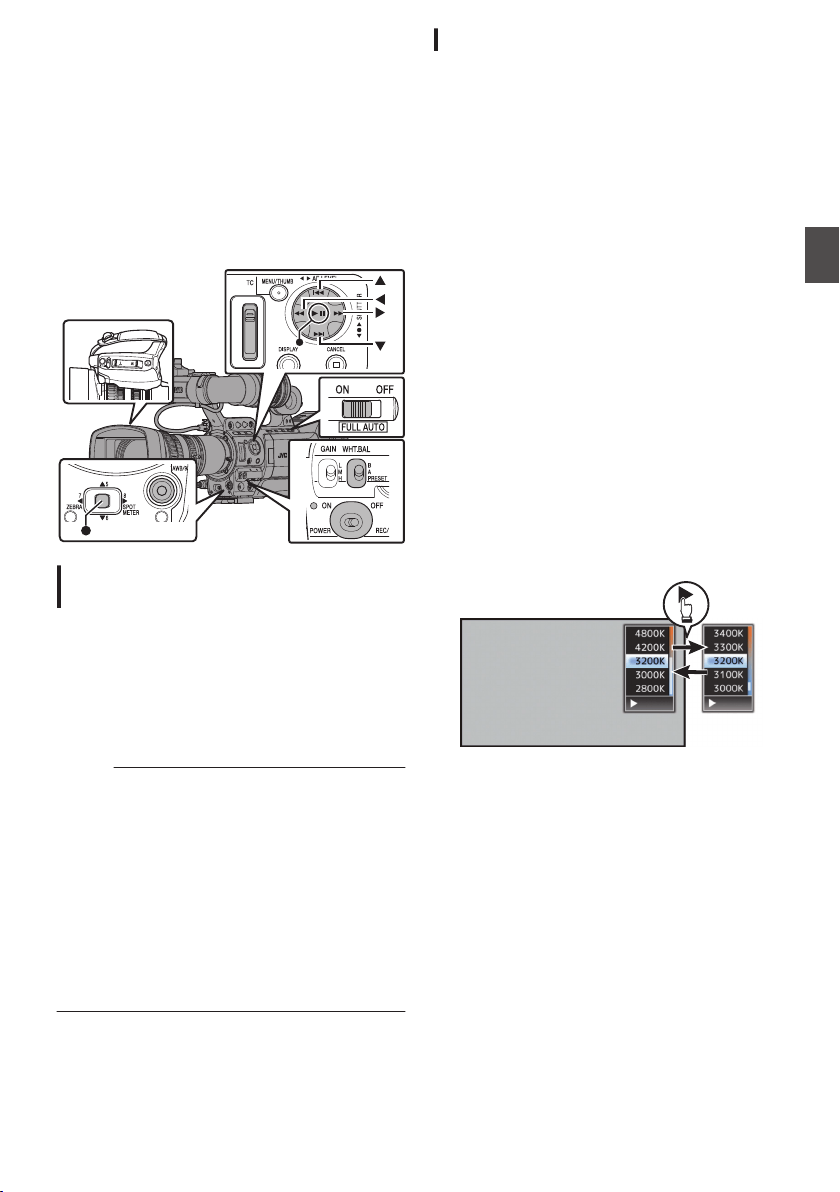
Adjusting the White
Balance
Adjust the white balance according to the color
temperature of the lighting. You can select the
adjustment mode according to the shooting
conditions.
As the color of the light (color temperature) varies
according to the light source, it is necessary to
readjust the white balance when the main light
source illuminating the subject changes.
.
ND FILTER
1/64
1/16
1/4
OFF
Manual White Balance Mode (Manual
Switching)
0
You can select the white balance with the
[WHT.BAL B/A/PRESET] switch.
0
Use the [WHT.BAL B/A/PRESET] switch to
select “PRESET” (preset mode), “A” (memory A
mode), or “B” (memory B mode).
0
Select [Back], and press the Set button (R) to
return to the [White Balance] menu.
Memo :
0
You can set the Full Auto White Balance feature
to either [A], [B], or [PRESET] in [Camera
Function] B [FAW].
(A P114 [ White Balance ] )
0
In the FAW (Full Auto White Balance) mode, the
color temperature of the video is sampled
constantly and automatically to obtain the most
appropriate white balance level.
0
When [Camera Function] B [FULL AUTO] B
[White Balance] is set to “FAW” and the [FULL
AUTO] switch on the camera recorder is set to
“ON”, the setting is fixed at “FAW”.
Preset Mode (PRESET)
0
Two different color temperature settings are
registered on this camera recorder. You can
switch between them using the user button
assigned with the “AWB” function.
(Default setting: “3200K”1“5600K”)
0
The color temperature changes each time you
press the user button assigned with “AWB”.
(“Preset Temp.”1“Alternative Temp.”)
1
Set the [WHT.BAL B/A/PRESET] switch to
“PRESET”.
2
Press the user button that is assigned with
“AWB”.
Setting the [Preset Temp.] or [Alternative
Temp.] Values
You can change both the color temperature
settings in the Preset mode in the menu.
1
Open the [Preset Temp.] or [Alternative
Temp.] menu.
0
Select [Main Menu]
B
[Camera Process]
B
[White Balance]
B
[Preset Temp.] and
[Alternative Temp.], and press the Set button
(
R
).
0
The Color Temperature setting screen
appears.
.
▶Fewer▶More
Color Temperature
Detailed Selection
Screen
Color Temperature Selection Screen
2
Select the color temperature.
0
When selecting from a setting value (Color
Temperature Selection screen), use the
cross-shaped button (JK) to select the color
temperature.
[Setting Values: 7500K, 6500K, 5600K,
5200K, 4800K, 4200K, R3200K, 3000K,
2800K]
0
To select detailed values (Color
Temperature Detailed Selection screen)
0
Press the cross-shaped button (I) to
display the Color Temperature Detailed
Selection screen.
0
Use the cross-shaped button (JK) to
select a color temperature.
[Setting Values: 2300K to 15000K (in
100K increments)]
Adjusting the White Balance
63
Shooting
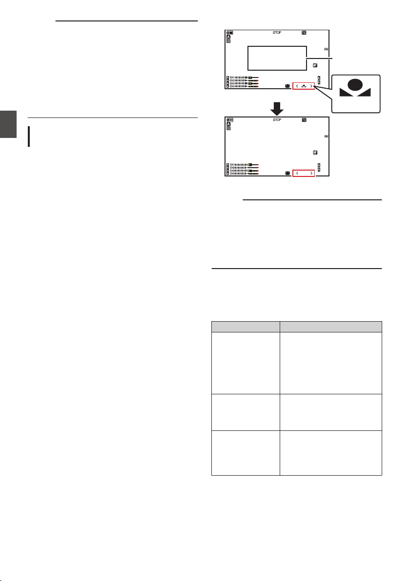
Memo :
0
Use the cross-shaped button (I) to switch
between the Color Temperature Selection
screen and the Color Temperature Detailed
Selection screen.
0
If [White Balance] has been assigned to the user
button, pressing the assigned user button will
display the Color Temperature Selection
screen.
(A P42 [Assignment of Functions to User
Buttons] )
Memory A Mode (A), Memory B Mode
(B)
0
Set to the white balance saved in Memory A or
Memory B.
0
When the [WHT.BAL B/A/PRESET] switch is set
to “A” or “B”, pressing the user button assigned
with “AWB” executes Auto White Balance. The
white balance will be automatically adjusted and
the adjusted value will be saved in Memory A or
Memory B.
1
Prepare the camera recorder.
A
Set the [POWER ON/OFF] switch to “ON”.
B
Set the [IRIS A/M] mode switch on the lens to “A”.
C
Set the [FULL AUTO] switch to “OFF”.
2
Set the [ND FILTER] switch according to the
lighting.
(A P62 [Setting the ND Filter] )
3
Set the [WHT.BAL B/A/PRESET] switch to “A”
or “B”.
4
Locate a place with similar lighting conditions
as the object to be shot, place a white object
near the center of the screen and zoom in to
fill the screen with white.
5
Press the [AWB/9] (Auto White Balance)
button.
0
The white detection frame appears when Auto
White Balance is activated. Fill the frame with
white completely.
0
While Auto White is starting up, “A<
y
>” or
“B<
y
>” appears on the screen. (
y
mark
appears blinking)
0
After the correct white balance is obtained, an
estimated value of the current color
temperature is displayed.
.
100min
50min
282min
A
1/100
F1. 6
0
dB
AE+6
ND 1 /64
5 . 6 f t
12 :34 :56
Jan 24 , 2014
00: 00:00.00
1920x1080
60 i HQ
100min
50min
282min
A
1/100
F1. 6
0
dB
AE+6
ND 1 /64
5 . 6 f t
12 :34 :56
Jan 24 , 2014
00: 00:00.00
1920x1080
60 i HQ
3700K
Result Display
[AWB] Activating
White Detection
Frame
Blinking
Caution :
0
Do not use highly reflective objects, such as
metals. Doing so may result in improper white
balance adjustment.
0
The Auto White function cannot provide optimum
white balance with an object outside the
adjustment range, for example when it contains
only a single color or not enough white color.
Error Message
If the white balance adjustment is not correctly
completed, one of the following messages will
appear for about 3 seconds.
Message Status
Auto White * NG:
Object
(*A or B)
Displayed when there is not
enough white color on the
object, or when the color
temperature is not suitable.
Use another white object and
adjust the white balance
again.
Auto White * Error:
Low Light
(*A or B)
Displayed when the lighting is
dark. Increase the lighting
and adjust the white balance
again.
Auto White * Error:
Over Light
(*A or B)
Excessive illumination.
Displayed when the lighting is
too bright. Decrease the
lighting and adjust the white
balance again.
64
Adjusting the White Balance
Shooting
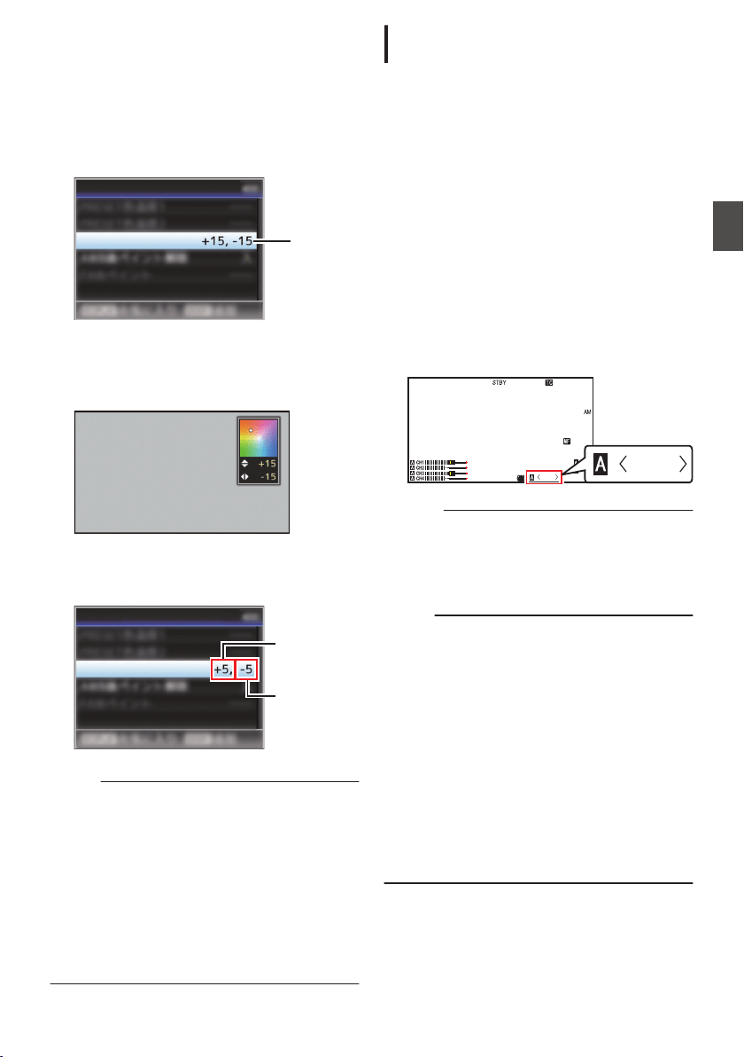
White Paint Adjustment
You can fine-tune the white balance saved in
Memory A or Memory B.
1
Select [Main Menu]
B [Camera Process] B
[White Balance]
B [AWB Paint] and press
the Set button (
R).
The White Paint Adjustment screen appears.
.
1
AWB Paint
White Balance
2
Adjust the R and B values.
Use the cross-shaped button (JK) to adjust R
value and (HI) to adjust B value.
.
B
R
3
Press the Set button (
R).
Returns to the [White Balance] screen.
.
B Value
R Value
AWB Paint
White Balance
Memo :
0
Selecting [AWB] will usually clear the White
Paint Adjustment value. But when [Main Menu]
B [Camera Process] B [White Balance] B
[Clear Paint After AWB] is set to “Off”, values will
not be cleared even when [AWB] is selected.
(A P118 [ Clear Paint After AWB ] )
0
If [White Balance] has been assigned to the user
button, pressing the assigned user button will
display the AWB Paint Adjustment screen.
(A P42 [Assignment of Functions to User
Buttons] )
Automatic White Balance Mode (FAW:
Fulltime Auto White balance)
1
Assign “FAW” (Full Auto White Balance) to
one of the three [WHT.BAL B/A/PRESET]
switches.
0
You can set the Full Auto White Balance
feature to either [A], [B], or [PRESET] in
[Camera Function] B [FAW].
(A P109 [ FAW ] )
0
“<FAW>” appears on the screen.
0
Set the [FULL AUTO] switch on the camera
recorder to “ON” to enter Automatic White
Balance mode. An appropriate white
balance is automatically adjusted according
to the color temperature of the lighting on the
object.
0
In this case, switching of the white balance
with the [WHT.BAL B/A/PRESET] switch is
disabled.
.
1/100
F1. 6
0
dB
AE+6
ND 1 /64
12 : 34 :56
Jan 24 , 2014
00: 00:00.00
5 . 6 f t
FAW
FAW
Caution :
0
The accuracy of [FAW] is inferior to that of Auto
White Balance.
0
When the power of the camera recorder is
turned on with the [FAW] mode selected, it takes
about 15 seconds for the colors to stabilize.
Memo :
0
When [Main Menu]
B
[Camera Function]
B
[User
Switch Set]
B
[AE Lock] is set to “AE/WB”, the
white balance when the user button that is
assigned [AE Lock] is pressed can be fixed.
(A P112 [ AE Lock ] )
0
You can switch the white balance using the
[WHT.BAL B/A/PRESET] switch when [Camera
Function] B [FULL AUTO] B [White Balance] is
set to “SW Set”.
(A P114 [ White Balance ] )
0
If [White Balance] has been assigned to the user
button, pressing the assigned user button will
display the FAW Paint Adjustment screen.
(A P42 [Assignment of Functions to User
Buttons] )
Adjusting the White Balance
65
Shooting
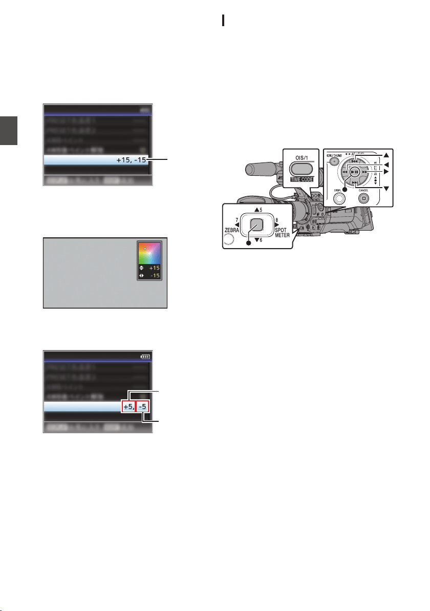
FAW Paint Adjustment
You can fine-adjust the white balance that was
automatically adjusted.
1
Select [Main Menu]
B [Camera Process] B
[White Balance]
B [FAW Paint] and press
the Set button (
R).
The FAW Paint Adjustment screen appears.
.
1
FAW Paint
White Balance
2
Adjust the R and B values.
Use the cross-shaped button (JK) to adjust R
value and (HI) to adjust B value.
.
B
R
3
Press the Set button (
R).
Returns to the [White Balance] screen.
.
B Value
R Value
FAW Paint
White Balance
White Shading Adjustment
0
Adjustment of white shading is needed when
you have changed the lens.
0
Although white balance may be appropriate at
the center of the image, this may not be the case
at the top and bottom areas.
If this is the case, the image will appear greenish
or yellowish. This phenomenon is due to the
characteristics of the lens. The process of
correcting this phenomenon is referred to as
white shading adjustment.
0
Perform this process after adjusting the white
balance.
.
Setup Prior Adjustment
1
Obtain the white balance on the camera.
(A P64 [Memory A Mode (A), Memory B Mode
(B)] )
2
Set the control of the camera lens as
follows.
A
Set the iris to F4.0 or narrower to obtain the
appropriate brightness.
If the brightness is insufficient at F4.0,
obtain the appropriate brightness such as
by adjusting the lighting.
B
When using a zoom lens, set to the center
of the zoom adjustment range.
3
Fill the monitor screen with a pattern box of
a uniform light source, or a piece of white
(plain) paper that is uniformly illuminated.
4
Set the chroma level of the monitor to the
maximum.
5
Check the monitor screen.
0
There is no need for adjustment if there is no
color at the top and bottom of the screen.
0
If the top of the screen is greenish and the
bottom is reddish or vice versa, continue this
adjustment.
66
Adjusting the White Balance
Shooting

Adjusting the White Shading
1
Set [Main Menu]
B [Camera Process] B
[White Balance]
B [Shading] to “On”.
2
Select [Adjust...] in [Shading] and press the
Set button (
R).
The White Shading Adjustment screen
appears.
.
Setting
Value
Evaluated Value Detection Frames
Sliding Bar for Setting
Evaluated Level Meter
3
Press the [OIS/1] button to set to perform
automatic adjustment.
You can use the R, G, B channels individually
to adjust the value of the evaluated level meter
up to a margin error of ±1 from the median value.
4
Adjust manually.
0
If you want to adjust manually after automatic
adjustment is performed, follow the steps
below.
0
You are recommended to adjust the G
(green) level only.
0
If manual adjustment in not necessary,
adjustment is complete at step 7.
5
Use the cross-shaped buttons (
HI) to
select the item to adjust from [R]/[G]/[B].
6
Adjust the setting value using the cross-
shaped buttons (
JK).
0
Adjust the sliding bar for setting while
referring to the evaluated level meter.
0
Adjust the values such that the evaluated
value falls almost at the center of the meter
using the K cross-shaped button if the
evaluated value of the channel to be
adjusted is larger than the median value, and
the J cross-shaped button if the evaluated
value is smaller than the median value.
7
Press the Set button (
R) to save the setting.
0
Make sure to press the Set button (R) to save
the setting.
0
Pressing the [CANCEL] button discards the
setting and returns to the menu screen at the
next higher level.
Memo :
0
There may be some delay in the changes of the
evaluated value after pressing the cross-shaped
button (JK).
0
Increasing the setting value suppresses the
colors at the bottom and enhances the colors on
top.
0
Adjustment is not possible in the following
cases. An error message will appear.
0
When the top and bottom ends of the frame
are overexposed
0
When the top and bottom ends of the frame
are underexposed
0
When there is significant difference in the
level between the top and bottom ends of the
frame
What is evaluated value?
This is a relative value (difference between the
top and bottom ends) with respect to the average
value of the R, G, B channels within the evaluated
value detection frames at the top and bottom of
the LCD monitor or viewfinder.
The evaluated value is positioned higher than the
center of the evaluated level meter when the level
at the top is higher than that at the bottom end.
Similarly, the evaluated value is positioned lower
than the center of the evaluated level meter when
the level at the top is lower than that at the bottom
end.
Adjust the evaluated value such that it falls
almost at the center of the meter.
Adjusting the White Balance
67
Shooting
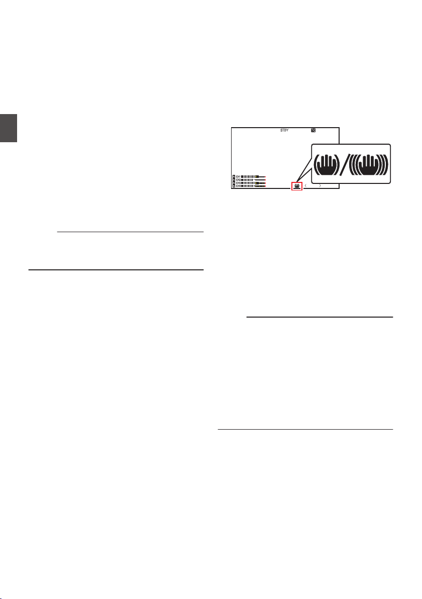
Adjusting the Camera
Image
The picture quality of the camera can be set using
the [Camera Process] menu.
As the adjustments are shown on the screen, you
can adjust the values while checking the picture
quality on the camera.
0
[Detail]
0
[Master Black]
0
[Black Toe]
0
[Knee]
0
[White Clip]
0
[Gamma]
0
[WDR]
0
[White Balance]
0
[Color Matrix]
0
[Color Gain]
0
[Reverse Picture]
0
[Shooting Mode]
Memo :
0
For details of the respective items, see the
[Camera Process] menu.
(A P114 [Camera Process Menu] )
Using the Image Stabilizer
F
Reduces blurring of images due to camera shake.
1
Check whether the image stabilizer feature
is turned ON or OFF.
If the image stabilizer icon (i/j) does not
appear on the screen display, the image
stabilizer function is OFF.
.
P13000K
1/100
F1. 6
0
dB
AE+6
ND 1 /64
12 : 34 : 56
Jan 24 , 2014
00: 00:00.00
5 . 6 f t
2
Press the [OIS/1] button to turn ON the
image stabilizer feature (when image
stabilizer feature is OFF).
The image stabilizer feature switches between
ON and OFF with every press of the [OIS/1]
button.
0
OFF:
Use this setting when the camera recorder is
secured, such as when using a tripod.
0
ON:
Reduces blurring of images due to camera
shake.
Memo :
0
Select [Main Menu] B [Camera Function] B
[OIS] B [Level] to set the correction level.
(A P108 [ Level ] )
0
Correction by this feature may not be sufficient
when camera shake is too strong.
0
“OIS” is assigned to [OIS/1] button in factory
default.
0
“OIS” can also be assigned to other user
buttons.
(A P42 [Assignment of Functions to User
Buttons] )
68
Adjusting the Camera Image
Shooting
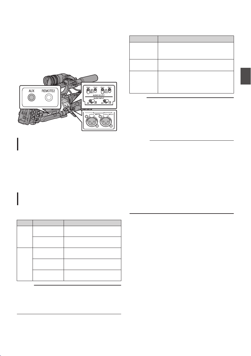
Audio Recording
You can record audio from the four channels
(CH-1/CH-2/CH-3/CH-4) in synchronization with
the video images on this camera recorder.
Select from the three options below to record the
audio.
0
Microphone connected to [AUX] terminal
0
Microphone connected to [INPUT1] terminal
0
Microphone connected to [INPUT2] terminal
.
Setting the Number of Recording
Channels
0
Set accordingly for slot A and slot B.
0
Set the number of recording channels in [Main
Menu] B [System] B [Record Set] B [Record
Format] B [WAudio]/[YAudio].
(A P133 [ W Audio ] )
(A P134 [ Y Audio ] )
Selecting Audio to Be Recorded in Each
Channel
Select the audio to be recorded in CH-1/CH-2/
CH-3/CH-4.
- Switch Setting Audio Input
CH-1
CH-3
AUX Audio input from [AUX]
terminal
INPUT1 Audio input from [INPUT1]
terminal
CH-2
CH-4
AUX Audio input from [AUX]
terminal
INPUT1 Audio input from [INPUT1]
terminal
INPUT2 Audio input from [INPUT2]
terminal
Memo :
0
Set the reference input level of “AUX” using
[Main Menu] B [A/V Set] B [Audio Set] B [AUX
Gain].
(A P127 [ AUX Gain ] )
Setting for [INPUT1]/[INPUT2] Input Channel
Set [AUDIO INPUT] signal selection switch 1 or 2
according to the devices to be connected to the
[INPUT1] and [INPUT2] terminals.
Setting Description
[LINE] Use this setting when connecting to
an audio device or other equipment.
The reference input level is +4 dBu.
[MIC] Use this setting when connecting to
a dynamic microphone.
[MIC+48V] Use this setting when connecting to
a microphone (phantom
microphone) that requires a +48 V
power supply.
Memo :
0
When “MIC” or “MIC+48V” is selected, set the
reference input level in [Main Menu] B [A/V
Set] B [Audio Set] B [Input1 Mic Ref.]/[Input2
Mic Ref.].
(A P127 [ Input1 Mic Ref. ] )
(A P127 [ Input2 Mic Ref. ] )
Caution :
0
When connecting a device that does not require
a +48 V power supply, make sure that it is not
set to the “MIC+48V” position.
0
When the [AUDIO INPUT] signal selection
switch 1 or 2 is set to “MIC”, check to ensure that
a microphone is connected to the [INPUT1]/
[INPUT2] terminal. If you increase the recording
level when a microphone is not connected,
noise from the input terminal may be recorded.
0
When a microphone is not connected to the
[INPUT1]/[INPUT2] terminal, set the [AUDIO
INPUT] signal selection switch 1 or 2 to “LINE”.
Audio Recording
69
Shooting
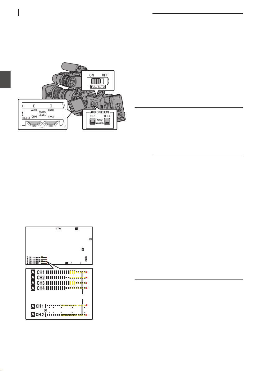
Adjusting Audio Recording Level
0
You can select to adjust the audio recording
levels for each of the four channels (CH-1/CH-2/
CH-3/CH-4) manually or automatically.
0
Set CH-1/CH-2 using the switch, and CH-3/
CH-4 using the menu.
.
For CH-1/CH-2
o Adjusting manually
1
Set the [AUDIO SELECT CH-1/CH-2 AUTO/
MANUAL] selection switch to “MANUAL”
for the channel to be adjusted manually.
2
Turn the [AUDIO LEVEL CH-1/CH-2]
adjustment knob corresponding to the
channel to adjust the level.
When [Audio Set] B [CH1 Limiter]/[CH2
Limiter] B [Threshold Level] is set to “Off”,
adjust such that the audio level meter does not
light up at -2 dB even for loud sounds.
(A P128 [ CH1/2 Limiter Mode ] )
.
P13000K
1/100
F1. 6
0
dB
AE+6
ND 1 /64
12 : 34 :56
Jan 24 , 2014
00: 00:00.00
5 . 6 f t
4030 20
10
0
-2dB
2 Channels
4 Channels
Memo :
0
For the recorded audio, you can set items such
as [Threshold Level], [Attack Time] or [Decay
Time] in [CH1 Limiter] or [CH2 Limiter].
0
If [CH1 Limiter]/[CH2 Limiter] B [Threshold
Level] is set to a value other than “Off”, the limiter
operates according to the value set.
0
You can adjust the level manually during the
recording, recording standby, and stop modes.
(A P128 [CH1 Limiter/CH2 Limiter] )
0
Set the reference audio level of [CH-1] and
[CH-2] to be recorded on SD cards in the [Main
Menu] B [A/V Set] B [Audio Set] B [CH1/2 Ref.
Level] menu to “-20dB”, “-18dB”, or “-12dB”.
(common for CH-1/CH-2)
(A P127 [ CH1/2 Ref. Level ] )
o Adjusting automatically
Set the [AUDIO SELECT CH-1/CH-2 AUTO/
MANUAL] selection switch to “AUTO” or the [FULL
AUTO] switch to “ON” to enter Automatic
Adjustment mode. The audio recording level is set
automatically according to the input level.
Memo :
0
When the [FULL AUTO] switch is set to “ON”,
mode switching of the [AUDIO SELECT CH-1/
CH-2 AUTO/MANUAL] selection switch is
disabled.
0
When [Main Menu] B [A/V Set] B [Audio Set] B
[CH1 Limiter]/[CH2 Limiter] B [Threshold
Level] is set to “Off” while in the automatic
adjustment mode, the limiter operates at
-6dBFS.
0
If [CH1 Limiter]/[CH2 Limiter] B [Threshold
Level] is set to a value other than “Off”, the limiter
operates according to the value set.
(A P128 [CH1 Limiter/CH2 Limiter] )
0
When [Main Menu] B [Camera Function] B
[FULL AUTO] B [Audio] is set to “SW Set”, you
can switch the audio recording mode with the
[AUDIO SELECT CH-1/CH-2 AUTO/MANUAL]
selection switch on the camera recorder even
when the [FULL AUTO] switch is set to “ON”.
(A P114 [ Audio ] )
70
Audio Recording
Shooting
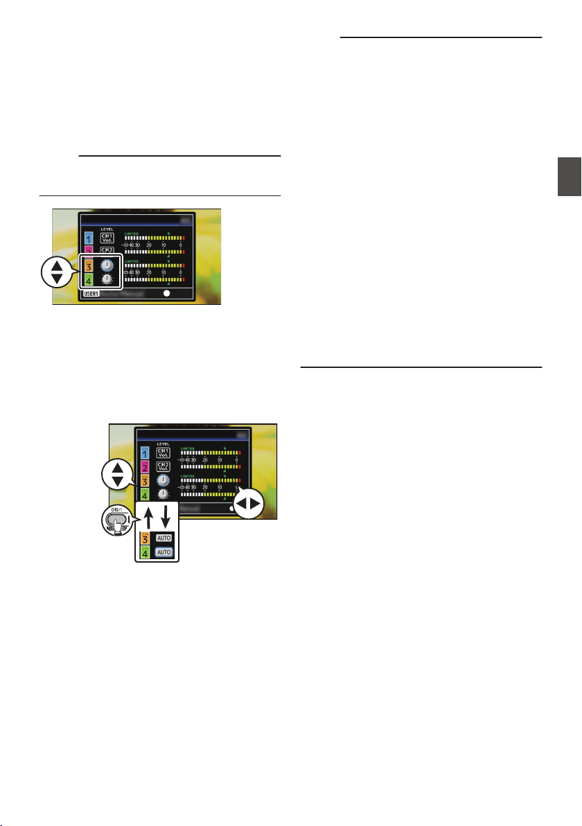
For CH-3/CH-4
1
Open the [CH3/4 Input Level] adjustment
screen.
0
Press the Set button (R) in [Main Menu] B
[A/V Set] B [Audio Set] B [CH3/4 Input
Level].
(A P127 [ CH3/4 Input Level ] )
0
The [CH3/4 Input Level] adjustment screen
appears.
Memo :
0
The input level cannot be set when the [FULL
AUTO] switch is set to “ON”.
.
Set
CH3/4 Input Level
2
Select whether to adjust manually or
automatically.
0
Use the JK cross-shaped buttons to select
the channel to set.
0
Press the [OIS/1] button to switch between
Manual and Auto.
0
During manual adjustment, adjust the level
using the H I cross-shaped buttons.
.
CH3/4 Input Level
Auto/Manual
Selection
Level Adjustment
Channel
Selection
3
Press the Set button (
R) to end the
adjustment.
0
Make sure to press the Set button (R) to save
the setting.
0
Pressing the [CANCEL] button discards the
setting and returns to the menu screen at the
next higher level.
Memo :
0
You can adjust the level manually during the
recording, recording standby, and stop modes.
0
For the recorded audio, you can set items such
as [Threshold Level], [Attack Time] or [Decay
Time] in [CH3 Limiter] or [CH4 Limiter].
0
If [CH3 Limiter]/[CH4 Limiter] B [Threshold
Level] is set to a value other than “Off”, the limiter
operates according to the value set.
(A P128 [CH3 Limiter/CH4 Limiter] )
0
Set the reference audio level of [CH-3] and
[CH-4] to be recorded on SD cards in the [Main
Menu] B [A/V Set] B [Audio Set] B [CH3/4 Ref.
Level] menu to “CH1/2 Link”, “CH1/2 -6dB”, or
“CH1/2 -12dB”. (common for CH3/CH4)
(A P127 [ CH3/4 Ref. Level ] )
0
When [Main Menu] B [A/V Set] B [Audio Set] B
[CH3 Limiter]/[CH4 Limiter] B [Threshold
Level] is set to “Off” while in the automatic
adjustment mode, the limiter operates at
-6dBFS.
0
If [CH3 Limiter]/[CH4 Limiter] B [Threshold
Level] is set to a value other than “Off”, the limiter
operates according to the value set.
(A P128 [CH3 Limiter/CH4 Limiter] )
Audio Recording
71
Shooting
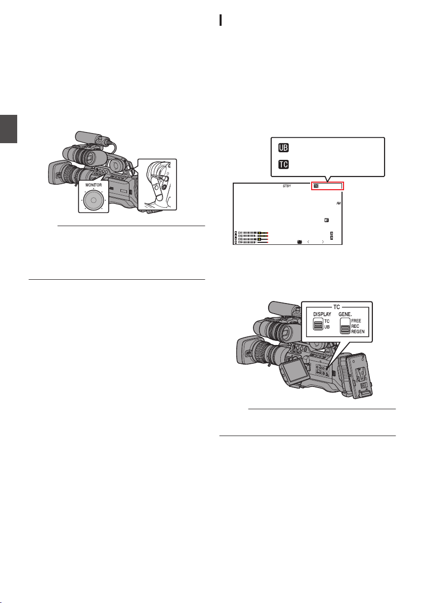
Audio Output during
Recording
0
You can check the recorded audio from the
monitor speaker or the earphone connected to
the [PHONES] terminal.
(A P163 [Connecting a Earphone] )
0
Adjust the volume of the monitor speaker or
earphone using the [MONITOR] adjustment
knob.
.
Memo :
0
The warning tone will not be output during
recording.
0
Note that raising the volume of the monitor
excessively may cause howling with the camera
mic.
Time Code and User’s Bit
Time code and user’s bit data are recorded with the
video in this camera recorder.
The time code and user’s bit are displayed on the
viewfinder and LCD monitor during playback or
recording. (Display screen)
Displaying Time Code and User’s Bit
The time code and user’s bit are displayed on the
viewfinder and LCD monitor during playback or
recording.
The display differs according to the menu settings.
1
Set [Main Menu]
B
[LCD/VF]
B
[Display
Settings]
B
[TC/UB] to “On”.
(A P123 [ TC/UB ] )
When “TC” or “UB” is selected, time code or
user’s bit data is displayed respectively on the
display screen.
.
P13000K
1/100
F1. 6
0dB
AE+6
ND 1/64
12 :34 :56
Jan 24 , 2014
00: 00:00.00
5 . 6 f t
00:00:00.00
FF EE DD 20
2
Select the display using the [TC DISPLAY]
switch on the LCD monitor.
Select time code display ([TC]) or user’s bit
display ([UB]).
.
Memo :
0
Values recorded on the SD card is displayed in
Media mode.
72
Audio Output during Recording
Shooting
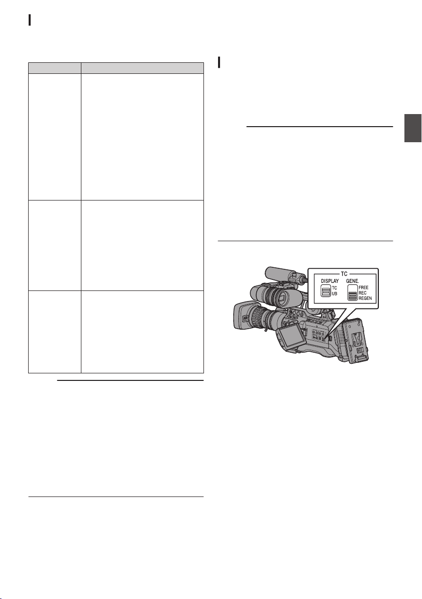
Time Code Operation Mode
Three types of time code operation (“FREE”,
“REC”, “REGEN”) can be selected with the [TC
GENE.] switch.
Setting Description
FREE
0
The time code operates in the
run mode at all times
regardless of the recording
status.
0
It continues to run even when
the power of the camera
recorder is turned off.
0
Synchronizes with the external
time code when an external
time code generator is
connected.
(A P78 [Synchronizing the
Time Code with an External
Time Code Generator] )
REC The time code operates in the run
mode during recording. It
continues to run in the order of the
recorded clips as long as the SD
card is not replaced. If the SD card
is removed and recording is made
on another card, time code will be
recorded on the new card from
where it was left off in the previous
card.
REGEN The time code operates in the run
mode during recording. When the
SD card is replaced, the last time
code recorded on the card is read
and recorded on a new card so that
the time code continues in running
order.
(A P74 [Presetting the Time
Code] )
Memo :
0
When [Main Menu] B [System] B [Record Set]
B [Rec Mode] is set to “Variable Frame”,
“Interval Rec” or “Frame Rec”, and the [TC
GENE.] switch is set to “FREE”, Rec Run mode
is activated.
(A P135 [ Rec Mode ] )
0
When [Main Menu] B [System] B [Record Set]
B [Record Format] B [WFormat]/[YFormat] is
set to “AVCHD”, Pre Rec enters Free Run mode.
(A P133 [ W Format ] )
(A P134 [ Y Format ] )
Setting Time Code
Generator
Presetting the Time Code
0
Time code and user’s bit data generated from
the internal time code generator are recorded.
0
This section describes how to set [TC/UB] B [TC
Preset].
(A P119 [ TC Preset ] )
Memo :
0
When the frame rate in [Main Menu] B [System]
B [Record Set] B [Record Format] B [WFrame
& Bit Rate]/[YFrame & Bit Rate] is set to “50p”,
“50i”, “25p” or “24p”, setting to “Drop” is
disabled.
(A P133 [ W Frame & Bit Rate ] )
(A P134 [ Y Frame & Bit Rate ] )
0
You can configure the setting without accessing
the [TC/UB] menu screen.
(A P75 [Setting Time Code without Opening
the Menu] )
Required Settings Before Preset
.
1
Set the [TC GENE.] switch to “REC” or
“FREE”.
0
[REC]:
Preset data in the time code generator
operates in run mode during recording
mode. Set this when recording continuous
time code in connecting frames.
0
[FREE]:
Time code starts to operate in run mode from
the preset time in the time code generator.
Time Code and User’s Bit
73
Shooting
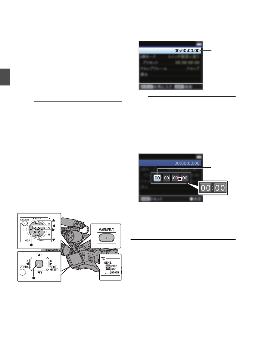
2
Select the framing mode for the time code
generator (only when the frame rate setting
is “60” or “30”).
Set using [Main Menu] B [TC/UB] B [Drop
Frame].
(A P119 [ Drop Frame ] )
0
[Drop]:
Sets the run mode of the time code generator
to drop frame mode. Use this setting when
placing emphasis on the recording time.
0
[Non Drop]:
Sets the run mode of the time code generator
to non-drop frame mode. Use this setting
when placing emphasis on the number of
frames.
Memo :
Drop frame/non-drop frame mode
0
When the frame rate setting in [Main Menu] B
[System] B [Record Set] B [Record Format] B
[Frame & Bit Rate] is “60p”, “60i”, or “30p”, the
actual number of frames per second is
approximately 59.94 (29.97). However, the time
code processing standard is “60p”, “60i”, or
“30p” frames. To make up for the frame number
discrepancy, the drop frame mode (Drop) drops
the 00 frame and 01 frame every minute except
for minutes that are multiples of 10. However, in
the case of “60p”, the 00, 01, 02 and 03 frame
are dropped.
0
The non-drop frame mode (Non Drop) does not
drop frames and ignores the discrepancy with
the actual time.
Presetting the Time Code
.
1
Select [Main Menu]
B [TC/UB] B [TC
Preset] and press the Set button (
R).
(A P119 [ TC Preset ] )
The [TC Preset] screen appears.
.
1
TC Preset
TC/UB
Memo :
0
When the [TC GENE.] switch is set to “REGEN”,
the parameter is displayed as “Regen” and
selection is disabled.
2
Set the time code (hour, minute, second,
frame).
Use the cross-shaped button (HI) to place the
cursor at the item to set, then use the cross-
shaped button (JK) to change the values.
.
TC Preset
TC/UB
During drop frame
During
non-drop frame
Cursor
Memo :
0
Press the [MARKER/2] button to reset each digit to
“0”. The cursor moves to the time digit (left).
3
Check the values and press the Set button
(
R).
0
The time code is set and the screen returns
to [TC/UB].
0
To cancel the setting, press the [CANCEL]
button.
4
Press the [MENU] button.
Returns to the normal screen.
74
Setting Time Code Generator
Shooting

Setting Time Code without Opening the
Menu
.
Memo :
0
Settings cannot be made in the following cases.
0
When the [TC GENE.] switch is set to
“REGEN”.
0
Menu screen is displayed.
0
The camera recorder is not in the Camera
mode.
Setting Time Code
1
Set the [TC DISPLAY] switch on the LCD
monitor to “TC”.
2
Set the [TC GENE.] switch to a setting other
than “REGEN”.
3
Hold down the [MENU] button and press the
[OIS/1] button.
The [TC Preset] setting screen appears.
.
TC Preset
During drop frame
During non-drop frame
Cursor
4
Set the time code (hour, minute, second,
frame).
Use the cross-shaped button (HI) to place the
cursor at the item to set, then use the cross-
shaped button (JK) to change the values.
Memo :
0
Press the [MARKER/2] button to reset each digit to
“0”. The cursor moves to the time digit (left).
5
Check the values and press the Set button
(
R).
0
The time code is set and the screen returns
to the normal screen.
0
To cancel the setting, press the [CANCEL]
button.
Caution :
0
When the camera recorder is switched to Media
mode during editing, editing will be canceled
and the screen will close.
0
When editing the time code, operation of the
[OIS/1] and [MARKER/2] buttons that are set in
[Main Menu] B [Camera Function] B [User
Switch Set] is disabled. [MARKER/2] functions
as the number reset button.
(A P111 [User Switch Set Item] )
Recording Time Code in Continuation of
the Recorded Time Code on SD Card
This camera recorder is equipped with the time
code reader.
1
Set the [TC GENE.] switch to “REGEN”.
0
When the camera recorder enters from
recording standby mode to recording mode,
it reads the time code already recorded on
the SD card and records the new time code
in continuation of that value.
0
The same data as the user’s bit already
recorded on the SD card is recorded.
Memo :
0
When the [TC GENE.] switch is set to “REGEN”,
the framing mode of the time code follows the
settings in [TC/UB] B [Drop Frame] instead of
the clip settings.
(A P119 [ Drop Frame ] )
Setting Time Code Generator
75
Shooting
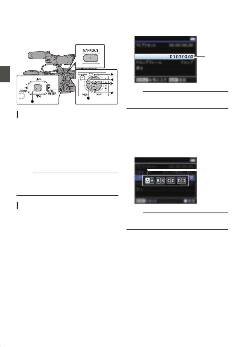
Setting the User’s Bit
You can add the date, time or an 8-digit
hexadecimal number as the user’s bit to the
recorded image.
.
Selecting a Recording Mode
Recording date/time information to the user’s
bit
1
Set [Main Menu]
B [TC/UB] B [UB Mode] to
“Date” or “Time”, and press the Set button
(
R).
(A P119 [ UB Mode ] )
The date or time information is recorded to the
user’s bit.
Memo :
0
When “Date” or “Time” is set, [Preset] appears
as “-” and cannot be set.
0
“Time” is displayed in the 24-hour format.
Presetting the User’s Bit
Recording arbitrary information (8-digit
hexadecimal) to the user’s bit
1
Set [Main Menu]
B [TC/UB] B [UB Mode] to
“SW Set”, and press the Set button (
R).
(A P119 [ UB Mode ] )
2
Move the cursor to [Preset] and press the
Set button (
R).
The [UB Preset] setting screen appears.
.
2
Preset
UB Mode
TC/UB
Memo :
0
When the [TC GENE.] switch is set to “REGEN”,
“Regen” is displayed and preset is disabled.
3
Use the cross-shaped button (
HI) to place
the cursor at the item to set, then use the
cross-shaped button (
JK) to change the
values.
Numbers between 0 and 9 or alphabets
between A and F can be specified for the user’s
bit.
.
TC/UB
Cursor
Memo :
0
Press the [MARKER/2] button to reset each digit to
“0”. The cursor moves to the left.
4
Check the values and press the Set button
(
R).
0
The user’s bit is set and the screen returns
to [TC/UB].
0
To cancel the setting, press the [CANCEL]
button.
5
Press the [MENU] button.
Returns to the normal screen.
76
Setting the User’s Bit
Shooting
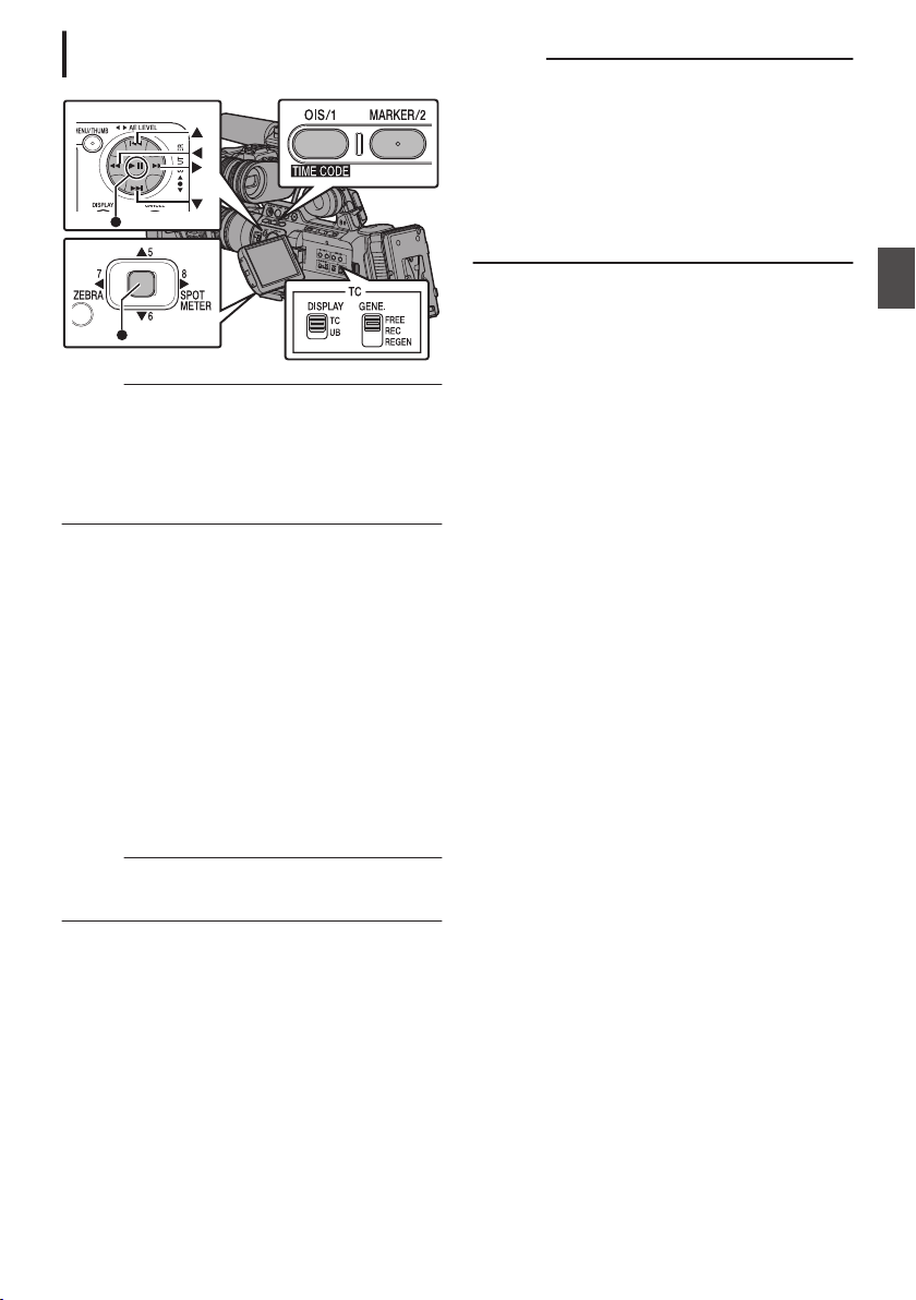
Setting User’s Bit without Opening the
Menu
.
Memo :
0
Settings cannot be made in the following cases.
0
When the [TC GENE.] switch is set to
“REGEN”.
0
Menu screen is displayed.
0
The camera recorder is not in the Camera
mode.
Setting the user’s bit
1
Set the [TC DISPLAY] switch on the LCD
monitor to “UB”.
2
Set the [TC GENE.] switch to a setting other
than “REGEN”.
3
Hold down the [MENU] button and press the
[OIS/1] button.
The [UB Preset] setting screen appears.
4
Set the user’s bit (numbers between 0 and
9, or alphabets between A and F).
Use the cross-shaped button (HI) to place the
cursor at the item to set, then use the cross-
shaped button (JK) to change the values.
Memo :
0
Press the [MARKER/2] button to reset each digit to
“0”. The cursor moves to the time digit (left).
5
Check the values and press the Set button
(
R).
0
The user’s bit is set and the screen returns
to the normal screen.
0
To cancel the setting, press the [CANCEL]
button.
Caution :
0
When the camera recorder is switched to Media
mode during editing, editing will be canceled
and the screen will close.
0
When editing the user’s bit, the [OIS/1] and
[MARKER/2] button operations that are set in
[Main Menu] B [Camera Function] B [User
Switch Set] are disabled. [MARKER/2] functions
as the number reset button.
(A P111 [User Switch Set Item] )
Setting the User’s Bit
77
Shooting
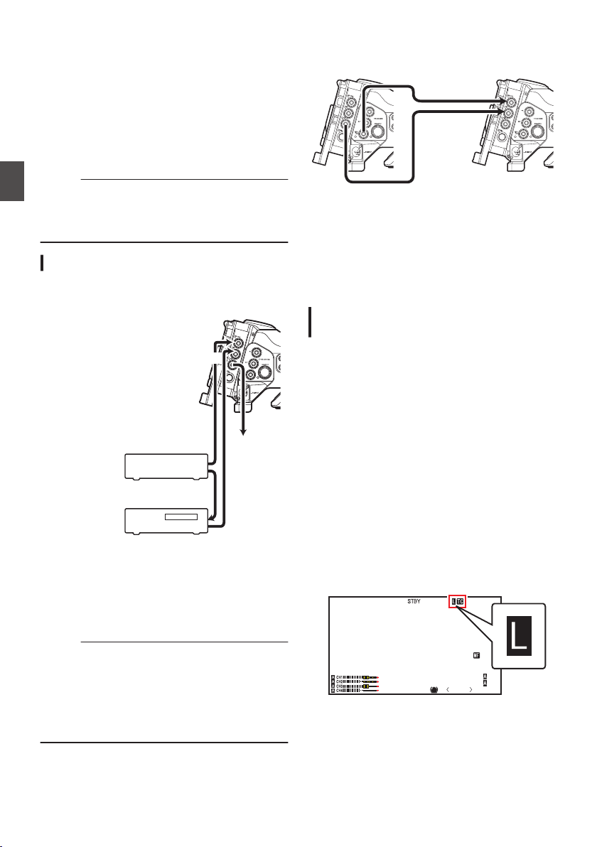
Synchronizing the Time
Code with an External
Time Code Generator
This camera recorder comes with a [TC IN]
terminal.
Connect a time code signal generator to the [TC
IN] terminal to synchronize with the SMPTE/EBU
LTC time code.
Memo :
0
After synchronization (slave lock), the internal
time code generator continues to run even if
there is no input from the external time code
generator.
Connection
Setting up the external time code generator as
a master device
.
GENLOCK
TC OUT
TC IN
To [TC IN]
Terminal of
Another
Camera
LTC Time Code
External Synchronizing Signal
External Synchronizing Signal
Master Device
External Time
Code Generator
Sync Signal
Generator
Slave Device
1
Input the external synchronizing signal to
the external time code generator and the
[GENLOCK] terminal of this camera
recorder.
Memo :
0
BB signals or HDTV tri-level synchronizing
signals are used as the external synchronizing
signal.
0
If the power of the camera recorder is turned on/
off during input of external synchronizing
signals, the screen may appear disrupted for a
few seconds. This is not a malfunction.
2
Input the SMPTE/EBU LTC time code from
the external time code generator to the [TC
IN] terminal of this camera recorder.
Connecting multiple devices, with one as the
master unit and the others as slave units
.
TC OUT
TC IN
GENLOCK
VIDEO OUT
Master Device
Slave Device
1
Connect the [TC OUT] terminal of the
master device with the [TC IN] terminal of
the slave device.
2
Connect the [VIDEO OUT] terminal of the
master device with the [GENLOCK]
terminal of the slave device.
Settings and Operation of the Camera
Recorder
1
Set to Camera mode.
(A P18 [Operation Modes] )
2
Set [A/V Set]
B [Video Set] B [Genlock
Input] to “BNC”.
(A P126 [ Genlock Input A B ] )
3
Set the [TC GENE.] switch to “FREE”.
4
Set LCD monitor or viewfinder to Display 1
screen.
5
Set the external time code generator or the
master device, and run the time code.
0
When the built-in time code generator is
synchronized with the external time code
data input, the Z icon on Display 1 screen
lights up.
0
When time code is not synchronized or time
code input is not available, the Z icon goes
out.
.
P13000K
1/100
F1. 6
0
dB
AE+6
ND 1 /6 4
12 :34 : 56
Jan 24 , 2014
00:00: 00.00
5 . 6 f t
78
Synchronizing the Time Code with an External Time Code Generator
Shooting
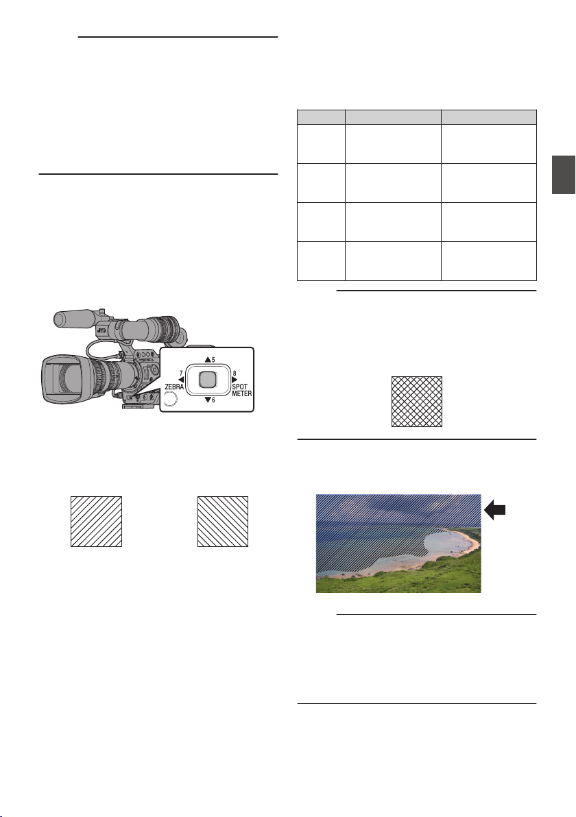
Memo :
0
The built-in time code generator will continue
operation even when the master device is
disconnected after synchronization.
0
User’s bit will become data in the master device.
0
While the [TC] terminal is connected, the time
code may be out of synchronization when the
[A/V Set] B [Video Set] B [HDMI/SDI Out]
setting of the Master device and Slave device is
being changed.
(A P125 [ HDMI/SDI Out ] )
Setting Zebra Pattern
When the luminance level range for displaying
zebra patterns is specified, diagonal lines (zebra
pattern) are displayed at areas with the specified
luminance levels during shooting.
.
1
Set the zebra display pattern.
Select the display pattern in [LCD/VF] B
[Shooting Assist] B [Zebra].
(A P121 [ Zebra ] )
.
Zebra 2 Display
Example
Zebra 1 Display
Example
2
Specify the brightness (luminance) level
range for displaying zebra pattern.
Set the maximum brightness limit in [LCD/VF]
B [Shooting Assist] B [Zebra] B [Top 1]/[Top
2], and the minimum brightness limit in [Bottom
1]/[Bottom 2].
Item Settings Options
Top 1 Maximum
brightness limit for
displaying Zebra 1
5% - 100%, Over
(in 5 % increments)
Bottom 1 Minimum
brightness limit for
displaying Zebra 1
0% - 100% (in 5 %
increments)
Top 2 Maximum
brightness limit for
displaying Zebra 2
5% - 100%, Over
(in 5 % increments)
Bottom 2 Minimum
brightness limit for
displaying Zebra 2
0% - 100% (in 5 %
increments)
Memo :
0
When [Zebra] is set to “1Pattern”, “Top 2” and
“Bottom 2” cannot be selected.
0
If the area specified by two zebra patterns
overlaps, the zebra patterns will also appear
overlapped, forming a grid-like display.
.
3
Display the zebra pattern.
Press the [7/H/ZEBRA] button to display the
zebra pattern in the specified range.
.
Memo :
0
“Zebra” is assigned to the [7/H/ZEBRA] buttons
in the factory default.
0
“Zebra” can also be assigned to other user
buttons.
(A P42 [Assignment of Functions to User
Buttons] )
Synchronizing the Time Code with an External Time Code Generator
79
Shooting
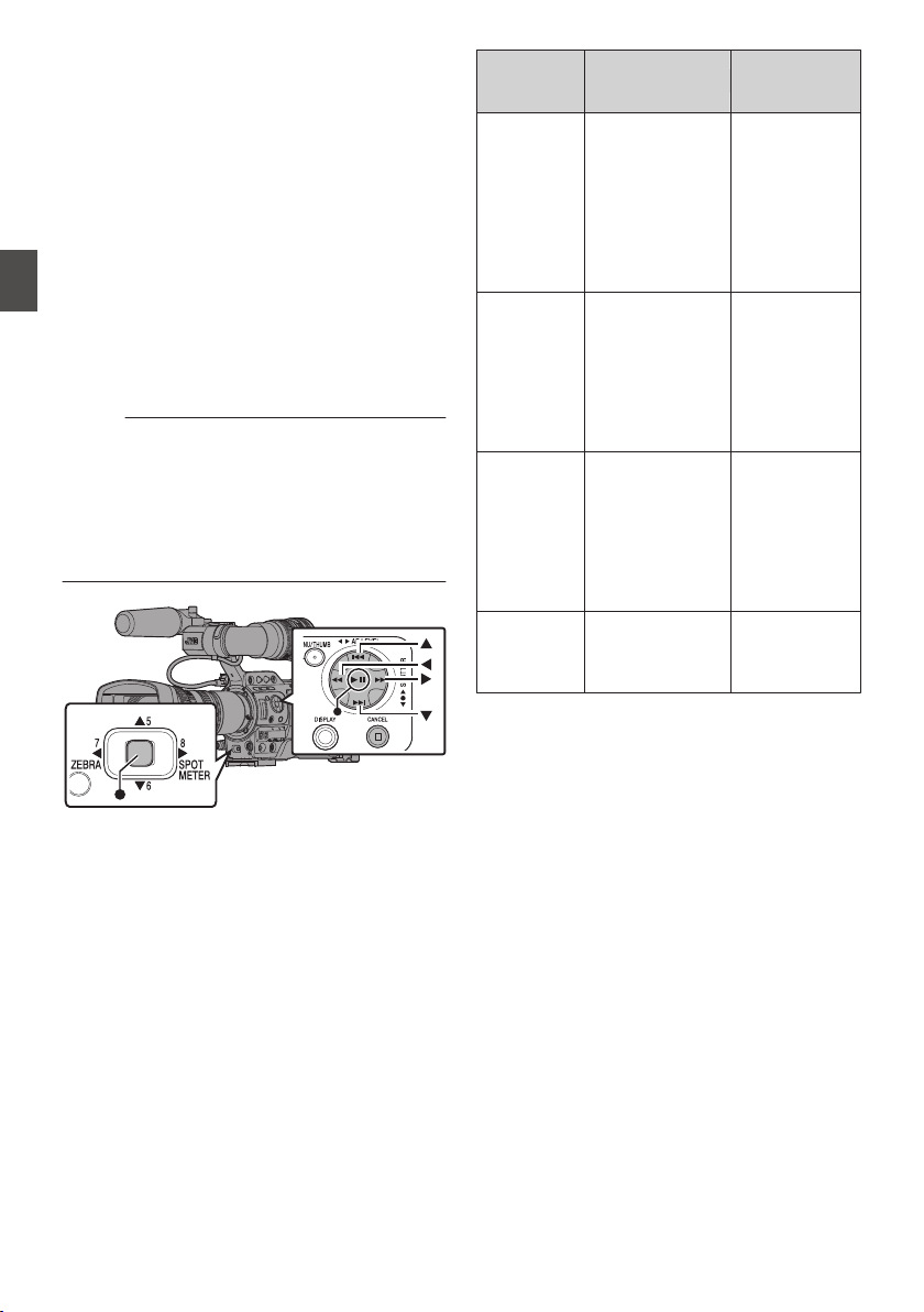
Setting Spot Meter
The brightness of the object during shooting is
displayed.
This function is useful when setting video or stage
lighting or when specifying camera exposure.
A cursor indicating the location and the brightness
(%) of that location are displayed in the images
shown on the LCD monitor and viewfinder screen.
0
Zebra patterns display the brightness of output
video signals.
(A P79 [Setting Zebra Pattern] )
0
This function allows you to check the brightness
of input images from the lens without depending
on image processing such as gamma curve. The
dynamic range of the camera recorder is 400 %
and a brightness range of 0 % to 400 % and
above is displayed.
Memo :
0
Spot meter may not be consistent with the zebra
display range. When [Camera Process] B
[Gamma] is set to “Cinema”, the 100IRE output
is not consistent with the 100 % display.
When an object of more than 400 % luminance
is detected, it is displayed as “400 %”.
(A P115 [ Gamma ] )
.
1
Select one of the following from [Main
Menu]
B [Camera Function] B [User Switch
Set]
B [Spot Meter].
(A P111 [ Spot Meter ] )
Item Settings
Color of Frame
Indicating the
Position
Max & Min
Displays the
brightness (%)
and positions of
the brightest and
darkest areas in
the screen.
Frames may also
be stopped at the
current positions.
0
Max: Green
0
Min: Yellow
Max Displays the
brightness (%)
and position of the
brightest area in
the screen.
Frames may also
be stopped at the
current positions.
Green
Min Displays the
brightness (%)
and position of the
darkest area in the
screen. Frame
may also be
stopped at the
current positions.
Yellow
Manual Displays the
brightness (%) of
the specified
position.
Green
(Blinks in green
when specifying
the position)
2
Assign the “Spot Meter” function to any of
the user buttons.
(A P42 [Assignment of Functions to User
Buttons] )
3
Press the user button that is assigned with
“Spot Meter”.
The operation switches as below when the
button is pressed.
80
Setting Spot Meter
Shooting
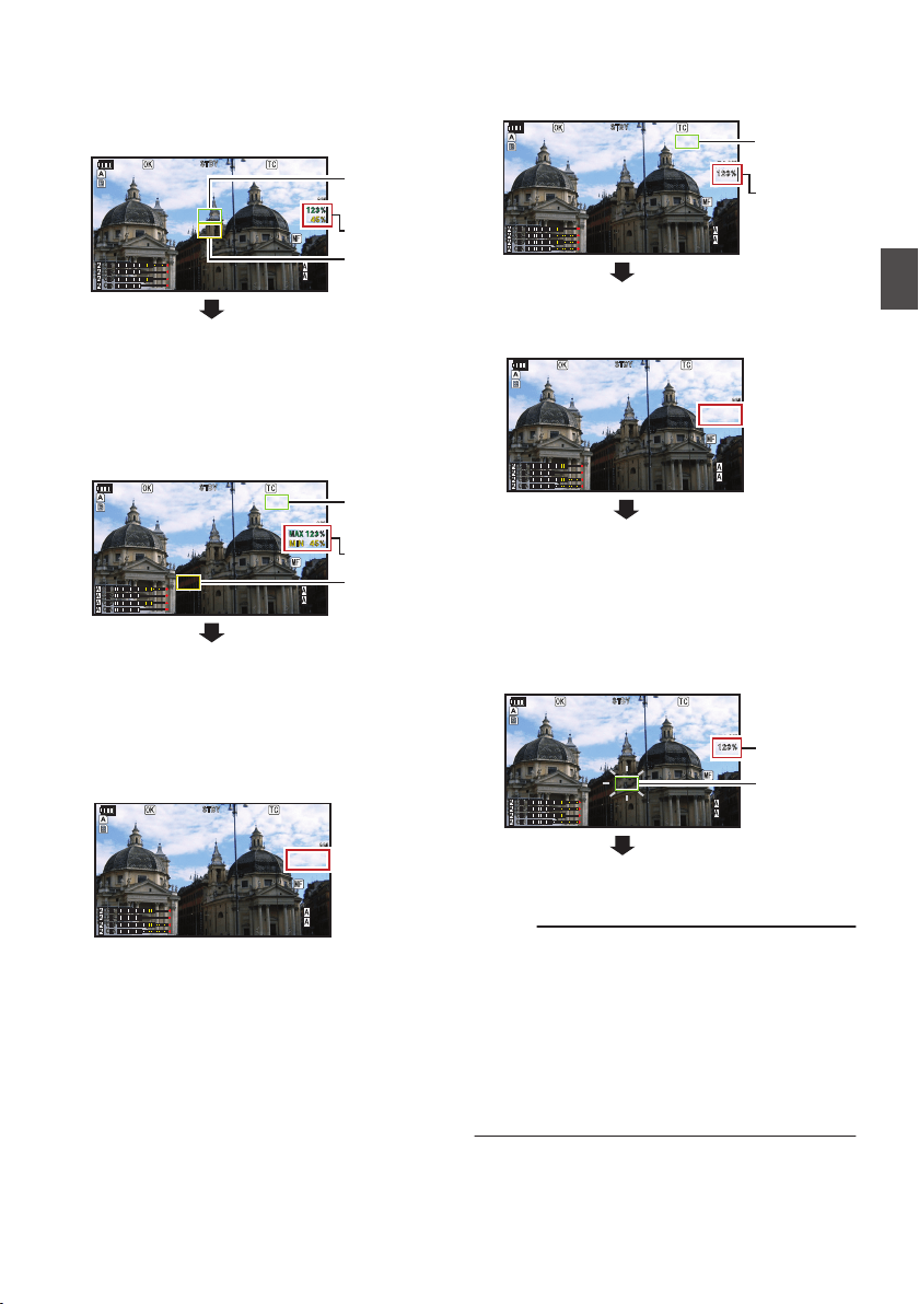
When [Max & Min]/[Max]/[Min] is selected
A
The cursors appear according to the setting
when the button is pressed.
Green and yellow frames appear, and the
brightness levels of these areas are displayed.
.
P 13000K
P 13000K
1/100
1/100
F1.6
F1.6
0dB
0dB
AE+6
AE+6
ND 1/64
ND 1/64
12:34:56
12:34:56
Jan 24,2014
Jan 24,2014
00:00:00.00
00:00:00.00
5.
5.6 f t
100min
100min
50min
50min
282min
282min
Cursor
Cursor
Brightness
Indication
(Yellow)
(Green)
B
Hold down the button in the state in A, the
positions of the brightest (Max) and darkest
(Min) areas in the screen are automatically
detected with regard to the changes of the
object, and the brightness level of these areas
are displayed.
.
P 13000K
P 13000K
1/100
1/100
F1.6
F1.6
0dB
0dB
AE+6
AE+6
ND 1/64
ND 1/64
12:34:56
12:34:56
Jan 24,2014
Jan 24,2014
00:00:00.00
00:00:00.00
5.
5.6 f t
100min
100min
50min
50min
282min
282min
(Min: Yellow)
Cursor
(Max: Green)
Cursor
Brightness
Indication
C
Pressing the button in the state in B stops the
automatic position detection. The frames are
fixed at the stopped positions and the
brightness levels are displayed.
D
By pressing the button, the cursors and
brightness indication disappear.
.
P 13000K
P 13000K
1/100
1/100
F1.6
F1.6
0dB
0dB
AE+6
AE+6
ND 1/64
ND 1/64
12:34:56
12:34:56
Jan 24,2014
Jan 24,2014
00:00:00.00
00:00:00.00
5.
5.6 f t
100min
100min
50min
50min
282min
282min
When [Manual] is selected
A
The brightness of the cursor position is
displayed when the button is pressed.
.
P 13000K
P 13000K
1/100
1/100
F1.6
F1.6
0dB
0dB
AE+6
AE+6
ND 1/64
ND 1/64
12:34:56
12:34:56
Jan 24,2014
Jan 24,2014
00:00:00.00
00:00:00.00
5.
5.6 f t
100min
100min
50min
50min
282min
282min
Cursor
(Green)
Brightness
Indication
B
By pressing the button, the cursors and
brightness indication disappear.
.
P 13000K
P 13000K
1/100
1/100
F1.6
F1.6
0dB
0dB
AE+6
AE+6
ND 1/64
ND 1/64
12:34:56
12:34:56
Jan 24,2014
Jan 24,2014
00:00:00.00
00:00:00.00
5.
5.6 f t
100min
100min
50min
50min
282min
282min
C
Hold down the button in the state in A or B, the
cursor blinks in green.
Move the cursor with the cross-shaped button
(JKHI) to specify the position to display the
brightness.
When you decide on the position, press the Set
button (R) to confirm.
.
P 13000K
P 13000K
1/100
1/100
F1.6
F1.6
0dB
0dB
AE+6
AE+6
ND 1/64
ND 1/64
12:34:56
12:34:56
Jan 24,2014
Jan 24,2014
00:00:00.00
00:00:00.00
5.
5.6 f t
100min
100min
50min
50min
282min
282min
(Blinks in
green)
Cursor
Brightness
Indication
D
Frames are fixed at the stopped positions and
the brightness is displayed.
Memo :
0
When moving the cursor position, [Shutter]/[AE
Level] control is disabled.
0
When the brightness is 0 % in the entire screen,
the frame is fixed in the center.
0
If the cursor is outside the “4:3” range, changing
[Main Menu] B [System] B [Record Set] B
[Record Format] B [SD Aspect] from “16:9” to
“4:3” restores the cursor to the default position.
(A P135 [ SD Aspect ] )
Setting Spot Meter
81
Shooting
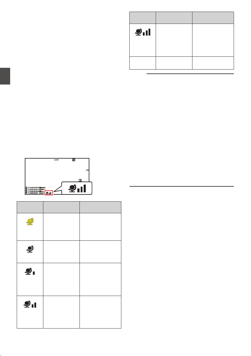
Acquiring Positioning
Information by GPS
This camera recorder comes with a built-in GPS
function. The GPS function is able to record the
positioning information.
During playback, you can also display the recorded
information on the playback screen.
(A P98 [Playing back] )
1
Set [Main Menu]
B [System] B [GPS] to
“On”.
0
Positioning starts when the H icon on the
display screen starts blinking.
0
After positioning is complete, the H icon
switches to a solid light and records the
positioning information during shooting.
0
The icon that appears on the screen
changes according to the condition of signal
reception from the GPS satellite.
0
The GPS function is able to record the
positioning information. However, the date/
time information (atomic clock) can be
recorded only when [Format] is set to
“AVCHD” on the slot to record to.
.
P13000K
1/100
F1. 6
0dB
AE+6
ND 1 /64
12 : 34 : 56
Jan 24 , 2014
00: 00:00.00
5 . 6 f t
Display
Reception
Status
Positioning Status
.
(Yellow)
[GPS] is set to
“On”, but signal
cannot be
received
GPS signal cannot
be received. UTC
and positioning
information cannot
be obtained.
.
(Blink)
GPS search in
progress
UTC information
can be obtained,
but not positioning
information.
.
GPS reception
in progress
(signal strength:
weak)
Receiving weak
GPS signal. UTC
and positioning
information can be
obtained and
recorded.
.
GPS reception
in progress
(signal strength:
medium)
Receiving GPS
signal. UTC and
positioning
information can be
obtained and
recorded.
Display
Reception
Status
Positioning Status
.
GPS reception
in progress
(signal strength:
strong)
Receiving strong
GPS signal. UTC
and positioning
information can be
obtained and
recorded.
(No
display)
GPS function is
turned off
The [GPS] item is
set to “Off”.
Memo :
0
If positioning cannot be performed after waiting
for several minutes, this means GPS reception
is poor, and there is difficulty in receiving data.
Move to an open place with no obstructions.
Otherwise, GPS information will not be recorded
when shooting is performed.
0
Signal may not be received depending on
circumstances such as locations that are
indoors or surrounded by tall buildings, or the
geographical conditions.
Precision error may occur in the position
information depending on the conditions of
reception.
0
Even when positioning is in progress,
information may be disrupted depending on the
condition of signal reception.
0
When [GPS] is set to “Off”, and the SDI output is
1080/59.94p or 1080/50p, changing [GPS] to
“On” switches the SDI output to 1080/59.94i or
1080/50i.
82
Acquiring Positioning Information by GPS
Shooting

Viewing Recorded Videos
Immediately (Clip Review)
You can check (review) the last recorded video clip
on the screen.
However, the video clip cannot be played back if
the settings of the camera recorder are different
from the video format (Resolution/Frame & Bit
Rate/SD Aspect) of the clip.
(A P133 [ W Resolution ] )
(A P134 [ Y Resolution ] )
(A P133 [ W Frame & Bit Rate ] )
(A P134 [ Y Frame & Bit Rate ] )
(A P135 [ SD Aspect ] )
1
Assign the “Clip Review” function to any of
the user buttons.
* This excludes the [AUTO FOCUS/11] button.
(A P42 [Assignment of Functions to User
Buttons] )
2
Press the button assigned with the “Clip
Review” function during standby (“STBY”
is displayed).
Playback of the configured section starts.
Memo :
0
The video clip is played back according to the
setting in [Main Menu] B [Camera Function] B
[User Switch Set] B [Clip Review]. By default
setting (Last 5sec), the last 5 seconds of the clip
is played back.
(A P111 [ Clip Review ] )
0
When playback is complete, the camera
recorder exits Clip Review and returns to
“STBY” (recording standby) mode.
Caution :
0
During Clip Review, only the [CANCEL] and
[REC] buttons are enabled.
Press the [CANCEL] button to cancel clip review
and return to “STBY” (recording standby) mode.
Press the [REC] button to cancel clip review and
enter recording mode. It will take some time to
start recording after the button is pressed.
0
When the last clip is less than 5 seconds, the
whole clip is played back.
0
Only video clips in the currently selected slot can
be reviewed.
0
When there are no clips in the selected slot, Clip
Review function is disabled.
0
Clip Review is unavailable when Clip
Continuous Rec is paused (“STBYC”, yellow
text). To operate Clip Review, use the
[CANCEL] button to set to “STBYC” (white text)
first.
(A P89 [Clip Continuous Rec] )
0
Clip Review is unavailable when the camera
recorder is connected to an external equipment
and the equipment is in recording state.
0
Clip Review is unavailable when operating View
Remote via network connection.
(A P190 [View Remote Feature] )
Viewing Recorded Videos Immediately (Clip Review)
83
Shooting
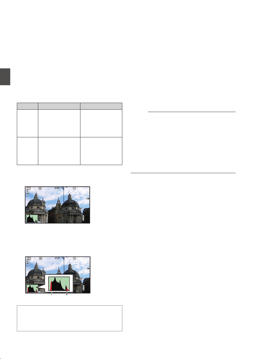
Using the Histogram
The histogram shows the brightness distribution,
and is employed mainly for checking the exposure
of the image.
1
Set the histogram feature to ON.
0
Set [Main Menu] B [LCD/VF] B [Display
Settings] B [Histogram] to “On”.
0
You can also press the user button that is
assigned with “Histogram”.
(A P111 [User Switch Set Item] )
2
Set the upper and lower limits of the
histogram display.
After setting, the brightness level is displayed in
red color.
Item Settings Options
Top Sets the maximum
brightness limit for
changing the
histogram display
color
5% to 110% (in 5 %
increments)
Bottom Sets the minimum
brightness limit for
changing the
histogram display
color
0% to 105% (in 5 %
increments)
o When the upper limit is set to 110% and the lower
limit to 0%
.
P 13000K
P 13000K
1/100
1/100
F1.6
F1.6
0dB
0dB
AE+6
AE+6
ND 1/64
ND 1/64
12:34:56
12:34:56
Jan 24,2014
Jan 24,2014
00:00:00.00
00:00:00.00
5.
5.6 f t
100min
100min
50min
50min
282min
282min
* The area in red is not displayed.
o When the upper limit is set to 90% and the lower
limit to 10%
.
P 13000K 1/100
1/100
F1.6
F1.6
0dB
0dB
AE+6
AE+6
ND 1/64
ND 1/64
12:34:56
12:34:56
Jan 24,2014
Jan 24,2014
00:00:00.00
00:00:00.00
5.
5.6 f t
100min
100min
50min
50min
282min
282min
To p
Bottom
How to read the histogram
0
The vertical axis denotes the number of pixels.
0
The horizontal axis denotes the pixel
brightness.
Recording
Simultaneously at Two
Different Definitions
By setting [System] to “HD+SD” or “HD+Web”, you
can record simultaneously at two different
definitions.
0
When HD+SD is selected:
Records a high-definition (HD) file to slot A and
a standard definition (SD) file to slot B at the
same time.
0
When HD+Web is selected:
Records a high-definition (HD) file to slot A and
a low bit-rate web file to slot B at the same time.
Web files can be used as a proxy file for the HD
file.
Memo :
0
If a recordable SD card is inserted into only one
of the slots, files will only be recorded to that slot.
0
The [Rec Mode] is fixed at “Normal”.
0
Clip Cutter Trig is disabled.
0
[Slot Mode] cannot be selected.
0
Clip Review can only be performed for slot A.
(“No Media” appears if there is no card in slot A
while a card is inserted into slot B.)
0
Playback of web files is only possible from slot
B when “HD+Web” is selected.
84
Using the Histogram
Shooting
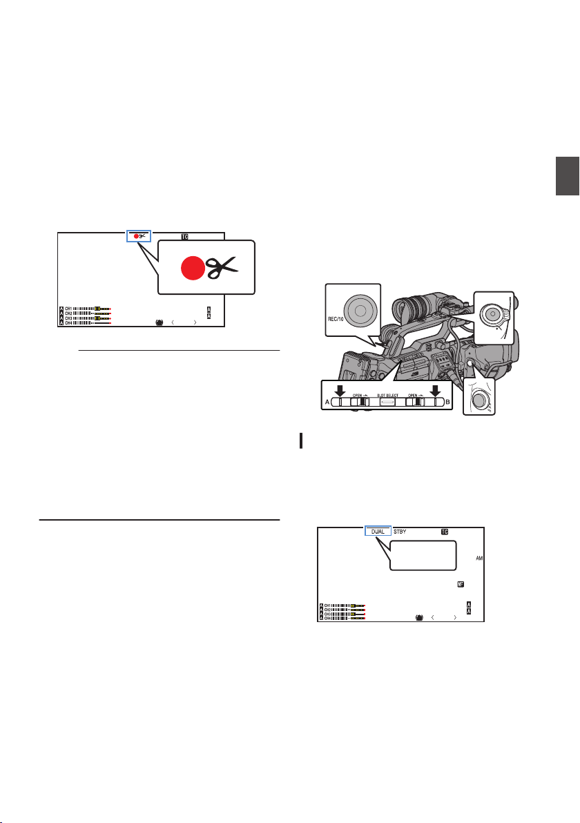
Splitting the Clips Freely
(Clip Cutter Trig)
You can split the clips freely without having to stop
recording during shooting.
1
Assign the “Clip Cutter Trig” function to
any of the user buttons.
(A P42 [Assignment of Functions to User
Buttons] )
2
Press the user button that is assigned with
“Clip Cutter Trig” during shooting.
A clip cut icon (Q) appears on the display
screen for 3 seconds, and the clip is split.
.
P13000K
1/100
F1. 6
0dB
AE+6
ND 1 /6 4
12 :34 : 56
Jan 24 ,2014
00:00: 00.00
5 . 6 f t
Memo :
0
Clips cannot be split again for a few seconds
after the operation is performed.
0
This item cannot be used when [Slot Mode] is
set to “Backup”.
0
Available only when [System] is set to “HD” or
“SD”.
(A P87 [Backup Rec] )
0
This item cannot be used when [Rec Mode] is
set to a value other than “Normal” or “Pre Rec”.
(A P135 [ Rec Mode ] )
0
The split clips are recorded seamlessly without
interruptions in the video.
Dual Rec
0
If both the slots are loaded with recordable cards
in the factory default ([Slot Mode] is set to
“Series”), pressing the [REC] button starts
recording only to the media in the selected slot.
When the remaining space in the selected
media runs out, recording continues by
automatically activating the media in the other
slot.
0
If both the slots are loaded with recordable cards
in the Dual Rec mode ([Slot Mode] is set to
“Dual”), pressing the [REC] button starts
recording simultaneously to the media in both
the slots.
0
The clips recorded to the media in both the slots
are identical, and two clips of the same content
can be created only on this camera recorder.
(A P136 [ Slot Mode ] )
.
REC
HOLD
REC
Setting to Dual Rec Mode
1
Set [Main Menu]
B [System] B [Record
Set]
B [Slot Mode] to “Dual”.
(A P136 [ Slot Mode ] )
“DUAL” appears on the display screen.
.
P13000K
1/100
F1. 6
0dB
AE+6
ND 1 /6 4
12 :34 : 56
Jan 24,2014
00:00: 00.00
5 . 6 f t
DUAL
Splitting the Clips Freely (Clip Cutter Trig)
85
Shooting
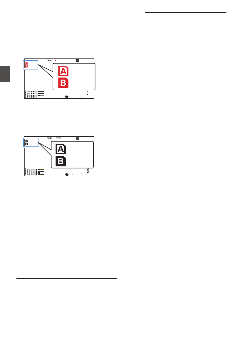
2
Start recording.
0
Insert recordable media in both slots, and
press the [REC] button.
0
In the Dual Rec mode, recording to the media
in both slots starts at the same time.
0
Both the card slot marks turn red, and the
status indicators of both the card slots also
light up in red.
.
P13000K
1/100
F1. 6
0dB
AE+6
ND 1 /6 4
12 :34 : 56
Jan 24,2014
00:00: 00.00
5 . 6 f t
100min
50min
REC
Lit in red
3
Stop recording.
0
Press the [REC] button again.
0
Recording to both slots stops, and both the
card slot marks turn white.
0
The same clips are recorded to both cards.
.
P13000K
1/100
F1. 6
0dB
AE+6
ND 1 /6 4
12 :34 : 56
Jan 24,2014
00:00: 00.00
5 . 6 f t
100min
50min
White
Memo :
0
During recording in the Dual Rec mode, both the
card slot marks light up in red.
0
During recording in the Dual Rec mode to two
cards with a different amount of remaining
space, if the space of one card runs out,
recording to both slots will stop automatically.
After recording stops, recording automatically
resumes for the card with remaining space.
Although the clips are separated in this case, the
clips can be seamlessly joined by arranging
them on the timeline of the editing software since
they are recorded seamlessly.
0
If the last clip on the cards that are inserted in the
two slots are different from each other, and the
time code operating mode is set to “Regen”, the
Regen mode for the selected card slot will be
enabled in the next recording.
Caution :
0
To perform recording in the Dual Rec mode, it is
recommended that you start recording by
making use of two cards with the same capacity
and from the formatted state.
0
You can combine the use of the Dual Rec mode
with a special recording mode. While in the Dual
Rec mode, you can also set [Rec Mode] to
“Normal”, “Pre Rec”, “Clip Continuous”, “Interval
Rec”, “Frame Rec”, or “Variable Frame”. When
[Main Menu]
B
[System]
B
[Record Set]
B
[Record Format]
B
[
W
Format] is set to “AVCHD”,
“Clip Continuous” cannot be selected.
(A P89 [Special Recording] )
(A P135 [ Rec Mode ] )
(A P133 [ W Format ] )
0
When both slots are inserted with recordable
cards, the Dual Rec (simultaneous recording)
operation can be performed. If a recordable
media is only inserted in one of the slots, you can
also start recording with one card.
0
In the Dual Rec mode, continuous recording by
switching from one slot to another cannot be
performed. Continuous recording will not be
performed if a recordable media is inserted in a
slot after recording to the other slot has started.
0
When recording to one slot is in progress with
the recorder set to the Dual Rec mode, inserting
a recordable media to the other slot does not
enable the Dual Rec operation. To perform the
Dual Rec operation, stop recording temporarily
(excluding pausing recording in the Clip
Continuous Rec mode), and start again.
0
When one of the cards is accidentally removed
while recording is in progress in the Dual Rec
mode, recording to the card in the other slot will
continue. However, repair of the accidentally
removed card by the recovery function may fail.
0
If an error occurs on one of the cards while
recording is in progress in the Dual Rec mode,
recording of the erroneous card stops, while that
of the other card continues.
0
Operations on clips recorded in the Dual Rec
mode, such as clip deletion in the Media mode
or appending of OK marks, can only be
performed on the card in the selected slot.
86
Dual Rec
Shooting
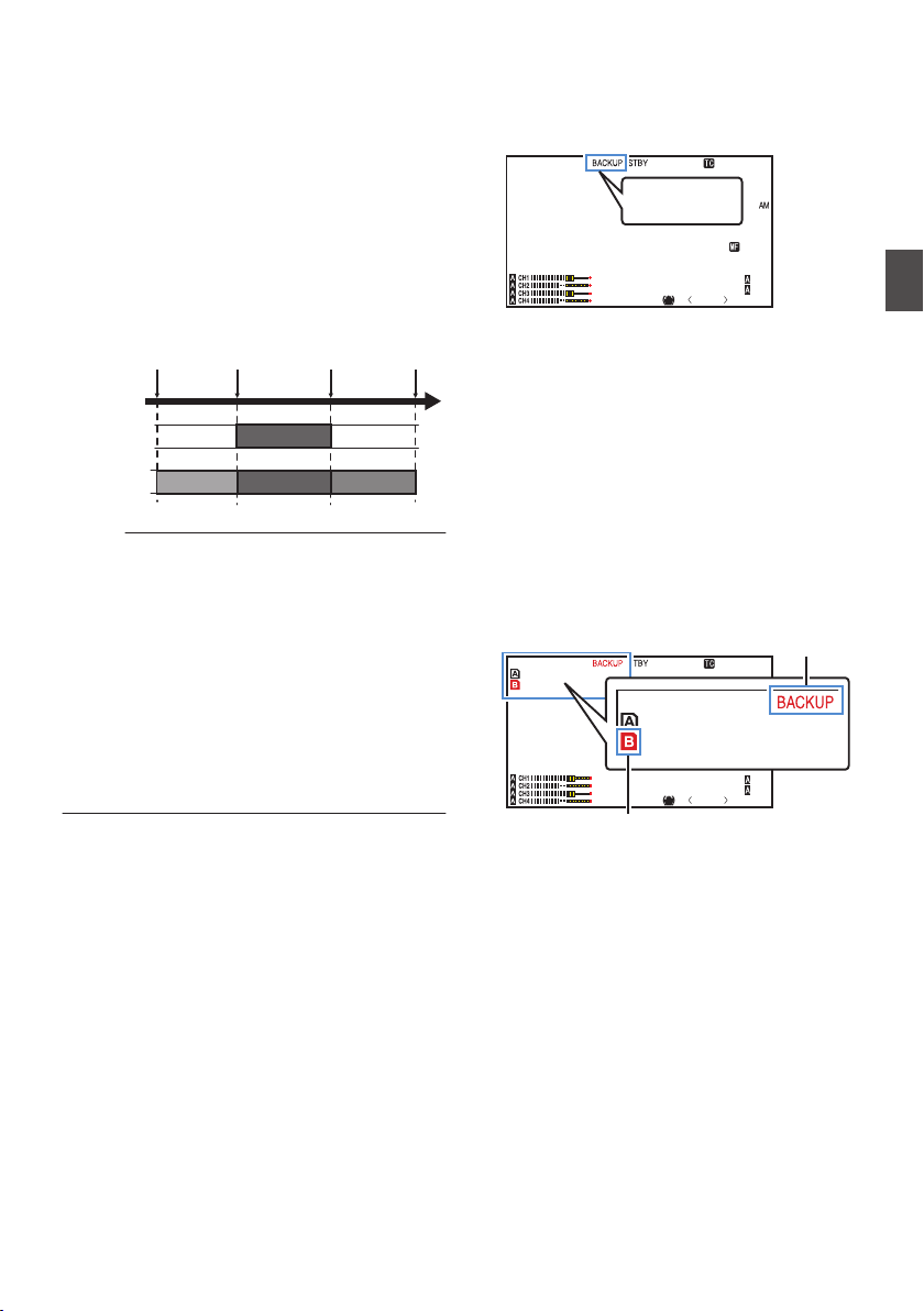
Backup Rec
0
The Backup Rec mode allows you to make use
of the media in slot B for backup recording by
controlling the starting and stopping of recording
in slot B without using the [REC] button.
0
Start or stop the recording using [Main Menu] B
[System] B [Record Set] B [Slot Mode] B
[Backup Rec] or press the user button that is
assigned with “Backup Trig”.
(A P136 [ Slot Mode ] )
(A P111 [User Switch Set Item] )
.
Slot B
Slot A
Clip 3
Clip 2
Clip 1
Clip 2
Slot B stops
recording
Slot A stops
recording
Slot A starts
recording
Slot B starts
recording
Memo :
0
During the Backup Rec mode (when [Slot
Mode] is set to “Backup”), you can control
recording to the 2 slots at different timings, and
backup recording can only be performed on this
camera recorder.
(A P136 [ Slot Mode ] )
0
You can record without worrying about missing
the important scenes by setting slot B to be
always recording (backup recording) and using
the [REC] button to start/stop recording of only
the required scenes in slot A.
0
It is recommended to use a media with high
capacity in slot B.
1
Set [Main Menu]
B [System] B [Record
Set]
B [Slot Mode] to “Backup”.
(A P136 [ Slot Mode ] )
“BACKUP” appears on the display screen.
.
P13000K
1/100
F1. 6
0dB
AE+6
ND 1 /6 4
12 :34 : 56
Jan 24,2014
00:00: 00.00
5 . 6 f t
BACKUP
2
Start backup recording. (Backup recording
into slot B)
0
Select “REC” in [Main Menu] B [System] B
[Record Set] B [Slot Mode] B [Backup
Rec] and press the Set button (R).
(A P136 [ Slot Mode ] )
0
You can also press the user button that is
assigned with “Backup Trig”.
(A P111 [User Switch Set Item] )
0
Backup recording into slot B starts. (The
characters “BACKUP” appear in red.)
0
The card slot mark of slot B turns red
(selected state), and the status indicator of
slot B also blinks in red.
.
P13000K
1/100
F1. 6
0
dB
AE+6
ND 1 /6 4
12 :34 : 56
Jan 24,2014
00:00: 00.00
5 . 6 f t
100min
50min
100min
50min
Red (selected)
Red
Backup Rec
87
Shooting
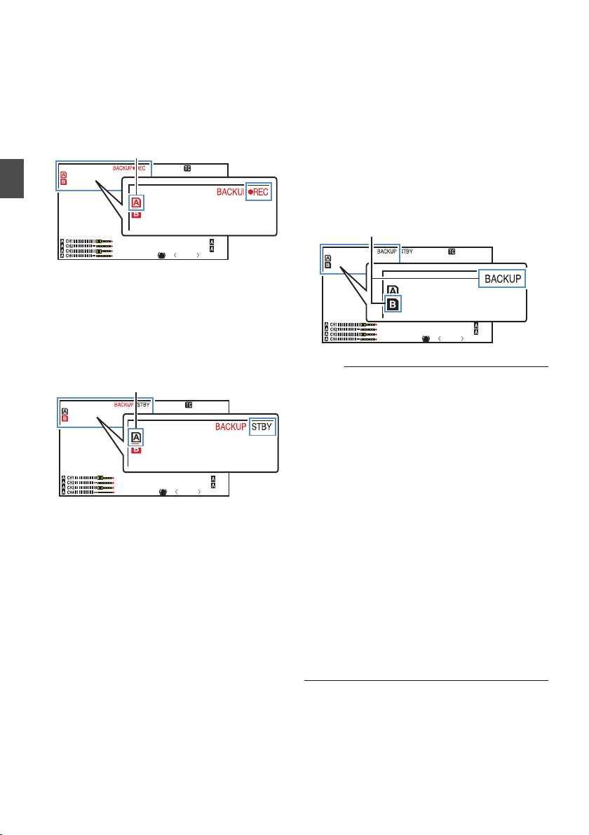
3
Start normal recording (normal recording
into slot A)
0
Press any of the [REC] buttons.
0
Recording into the media in slot A starts.
(The characters “RREC” appear in red.)
0
The card icon of slot A turns red (unselected
state), and the status indicator of slot A blinks
in red.
.
P13000K
1/100
F1. 6
0
dB
AE+6
ND 1 /6 4
12 :34 : 56
Jan 24,2014
00:00: 00.00
5 . 6 f t
100min
50min
100min
50min
Red (not selected)
4
Stop normal recording.
0
Press any of the [REC] buttons again.
0
Recording to slot A stops, and the card slot
mark of slot A turns white (unselected state).
0
The characters “RREC” (red) changes back
to “STBY” (white).
0
The status indicator of slot A goes out.
.
P13000K
1/100
F1. 6
0
dB
AE+6
ND 1 /6 4
12 :34 : 56
Jan 24,2014
00:00: 00.00
5 . 6 f t
100min
50min
100min
50min
White (not selected)
5
Stop backup recording.
0
Select [STBY] in [Main Menu] B [System] B
[Record Set] B [Slot Mode] B [Backup
Rec] and press the Set button (R).
(A P136 [ Slot Mode ] )
0
You can also press the user button that is
assigned with “Backup Trig”.
(A P111 [User Switch Set Item] )
0
Recording to slot B stops, and the card slot
mark of slot B turns white (unselected state).
0
The characters “BACKUP” changes back to
white.
0
The status indicator of slot B lights up in
green.
.
P13000K
1/100
F1. 6
0dB
AE+6
ND 1 /6 4
12 :34 : 56
Jan 24,2014
00:00: 00.00
5 . 6 f t
100min
50min
100min
50min
White
Memo :
0
During backup recording, if the space of one
card runs out, recording stops only for the card
that is full.
0
When recording to both slots is stopped,
recording in the Regen mode will be enabled for
the card slot in which recording started.
0
When recording is started in the other slot while
recording to one slot, the clip being recorded is
split and simultaneous recording to the other
card starts.
0
When recording is stopped for either slot A or B
while recording to both slots, the clip on the slot
which is still recording is split.
0
Although the clips are separated during
recording the clips can be seamlessly joined by
arranging them on the timeline of the editing
software since they are recorded seamlessly.
0
Clip Cutter Trig cannot be performed during
backup recording.
(A P85 [Splitting the Clips Freely (Clip Cutter
Trig)] )
0
When [Slot Mode] is set to “Backup”, [Rec
Mode] can only be set to “Normal”.
(A P135 [ Rec Mode ] )
88
Backup Rec
Shooting
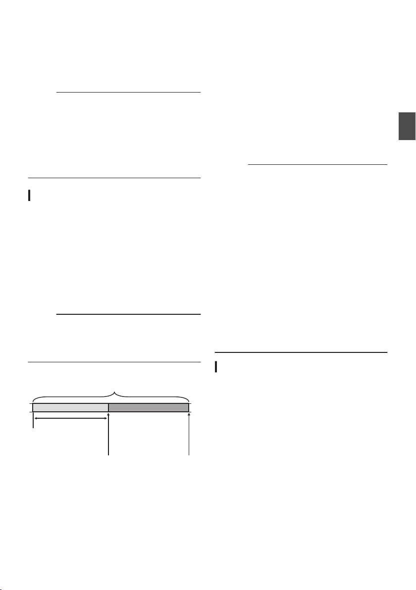
Special Recording
Besides the normal recording mode, five special
recording methods are available in this camera
recorder. They are Pre Rec, Clip Continuous,
Frame Rec, Interval Rec and Variable Frame.
Select a mode from [Record Set] B [Rec Mode].
Memo :
0
Set using [Main Menu] B [System] B [Record
Set] B [Rec Mode].
(A P135 [ Rec Mode ] )
0
When [Main Menu] B [System] B [Record Set]
B [Record Format] B [WFormat] is set to
“AVCHD”, “Clip Continuous” cannot be
selected.
(A P133 [ W Format ] )
Pre Rec
0
By setting the number of seconds in the [Pre Rec
Time], you can start recording video and audio
before actual recording starts based on the [Pre
Rec Time] setting.
0
When starting actual recording while the camera
recorder is in Recording Standby (STBYP)
mode, you can start recording a few seconds
earlier based on the [Pre Rec Time] setting.
0
Using Pre Rec allows you to record a complete
event without missing the initial scenes even if
you start the recording late.
Memo :
0
Pre Rec time can be set to “5sec” or “10sec” in
[Main Menu] B [System] B [Record Set] B [Rec
Mode] B [Pre Rec Time].
(A P135 [ Pre Rec Time ] )
.
(Recording stops)
Press [REC]
(Recording starts)
Press [REC]
Recording starts a
number of seconds
earlier based on the
[Pre Rec Time] setting
(Recorded video and audio)
Completed Clip
1
Set [Rec Mode] to “Pre Rec”.
(A P135 [ Rec Mode ] )
0
Set [Main Menu] B [System] B [Record
Set] B [Rec Mode] to “Pre Rec”.
0
The display changes (“STBY” B “STBYP”).
2
Press the [REC] button to start recording in
Pre Rec mode.
0
The display changes (“STBYP” B
“RRECP”) and the card slot status indicator
lights up in red.
0
Press the [REC] button again to pause
recording. The display changes (“RRECP”
B “STBYP”) and the card slot status
indicator lights up in green.
Caution :
0
When the interval between start and stop
recording is short, “STBYP” may not be
displayed immediately after recording is
complete.
“RRECP” B “STBYP” (“STBY” blinks in red) B
“STBYP” is displayed.
0
When the SD card becomes full during
recording, recording stops and “STOP” is
displayed.
0
Video and audio before the above mentioned
time may not be recorded after recording starts
in the following cases.
0
Immediately after power on
0
Immediately after recording stops
0
Immediately after switching from Media
mode to Camera mode
0
Immediately after setting [Rec Mode]
0
Immediately after the end of Clip Review
0
Immediately after changing file format
0
Immediately after changing video format
Clip Continuous Rec
0
In normal recording, when the recording stops,
the image, audio, and accompanying data from
the start till the end of the recording are recorded
as one “clip” on the SD card.
0
This mode allows you to consolidate several
rounds of “startstop recording” into one clip.
Example:
In normal recording, three clips are generated as
Recording 1, Recording 2, and Recording 3.
However, recording in this mode generates only
one clip.
Special Recording
89
Shooting
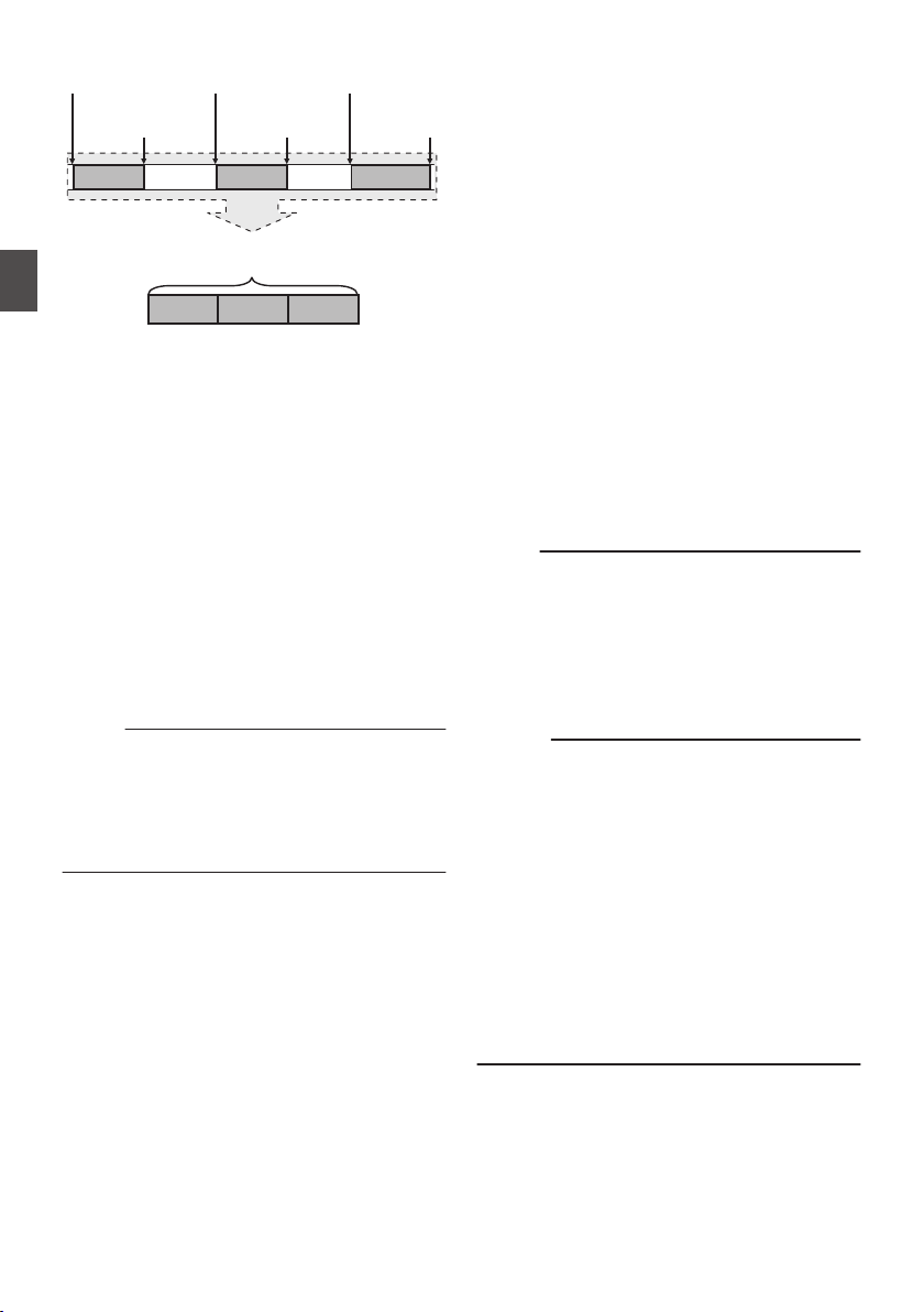
.
(Recorded video and audio)
Completed Clip
Recording 3
Recording 2
Recording 1
Recording 3
Recording 2
Recording 1
(Recording stops)
Press and hold [REC]
(Recording pauses)
Press [REC]
(Recording pauses)
Press [REC]
(Recording resumes)
Press [REC]
(Recording resumes)
Press [REC]
(Recording starts)
Press [REC]
1
Set “Rec Mode” to “Clip Continuous”.
(A P135 [ Rec Mode ] )
0
Set [Main Menu] B [System] B [Record
Set] B [Rec Mode] to “Clip Continuous”.
0
The display changes (“STBY” B “STBYC”).
2
Start recording. (Recording 1)
0
Press the [REC] button to start recording in
Clip Continuous mode.
0
The display changes (“STBYC” B
“RRECC”) and the card slot status indicator
lights up in red.
3
Pause recording.
0
Press the [REC] button again to pause
recording. The display changes (“RRECC”
B “STBYC” (yellow text)).
0
The card slot status indicator remains lighted
in red.
Memo :
0
When the [CANCEL] button is pressed while the
camera recorder is paused (STBYC), the
display changes (“STBYC” (yellow text) B
“STBYC” (blinking yellow text) B “STBYC”
(white text)), and a “clip” is generated. The card
slot status indicator lights up in green.
4
Resume recording. (Recording 2)
0
Press the [REC] button again to resume
recording. The display changes (“STBYC”
(yellow text) B “RRECC”).
0
The card slot status indicator remains lighted
in red.
5
Pause recording.
0
Press the [REC] button again to pause
recording. The display changes (“RRECC”
B “STBYC” (yellow text)).
0
The card slot status indicator remains lighted
in red.
6
Resume recording. (Recording 3)
0
Press the [REC] button again to resume
recording. The display changes (“STBYC”
(yellow text) B “RRECC”).
0
The card slot status indicator remains lighted
in red.
7
Press and hold the [REC] button.
0
Recording stops and the display changes
(“RRECC” B “STBYC”). A “clip” is
generated.
0
The card slot status indicator lights up in
green.
8
Press the [REC] button again.
0
The display changes (“STBYC” B
“RRECC”) and the card slot status indicator
lights up in red.
0
A new “clip” is generated from here.
Memo :
0
The following operations cannot be performed
while recording is paused (STBYC, yellow text).
0
Clip Review operation
(A P83 [Viewing Recorded Videos
Immediately (Clip Review)] )
0
Switching SD card slots
0
Switching operation mode
(A P18 [Operation Modes] )
Caution :
0
Do not remove the SD card during recording
(RRECC, red text) or recording pause
(STBYC, yellow text).
0
To remove the SD card in the “Clip
Continuous” mode, press the [CANCEL] button,
check that “STBYC” (white text) is displayed
and the card slot status indicator lights up in
green before you remove the card.
0
When the SD card becomes full during
recording, recording stops and “STOP” is
displayed.
0
When the [POWER ON/OFF] switch is turned off
during recording or recording pause, recording
stops and power is cut off after a clip is
generated.
90
Special Recording
Shooting
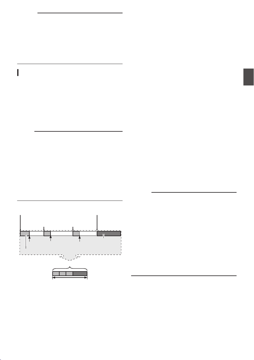
Caution :
0
If the power is cut off due to low battery power,
a proper clip may not be generated.
0
When [WFormat]/[YFormat] in the [Main
Menu] B [System] B [Record Set] B [Record
Format] menu is set to “AVCHD”, Clip
Continuous Rec cannot be performed.
(A P133 [ W Format ] )
(A P134 [ Y Format ] )
Frame Rec
In normal recording, when the recording stops, the
image and accompanying data from the start till the
end of the recording are recorded as one “clip” on
the SD card.
In this mode, recording starts with every press of
the [REC] button, and only the specified number of
frames is recorded.
The recording can be written to the media as a
single clip until it is stopped.
Memo :
0
Audio will not be recorded.
0
Until a specified amount of recordings is
accumulated, the file cannot be written to the
media.
0
If the specified amount is not reached when
recording is stopped, normal recording is
performed and frames are added to the ending
of the clip until the amount is reached. (Padding)
0
After the specified number of frames is recorded
and written to the media, recording will be
performed until the same number is
accumulated again.
.
Specific amount of data
Actual clips recorded to the media
Records number of frames specified in [Rec Frames]
(Padding data)
Normal recording
PausePausePause
Recording resumes
Recording resumes
Press [REC]Press [REC]
(Frame Rec stops)(Frame Rec starts)
Press and hold [REC]Press [REC]
1
Set [Rec Mode] to “Frame Rec”.
0
Set [Main Menu] B [System] B [Record
Set] B [Rec Mode] to “Frame Rec”.
(A P135 [ Rec Mode ] )
0
The display changes (“STBY” B “STBYM”).
2
Set the number of frames to record in [Rec
Frames].
0
Set using [Main Menu] B [System] B
[Record Set] B [Rec Mode] B [Rec Frames].
(A P135 [ Rec Frames ] )
3
Start recording.
0
Press the [REC] button to record only the
number of frames specified in [Rec
Frames] and pause.
0
The display changes (“STBYM” B “RRECM”
B “STBYM” (yellow text)).
0
The card slot status indicator lights up in
green.
4
Repeat Frame Rec.
0
Press the [REC] button again to record only
the number of frames specified in [Rec
Frames] and pause.
0
The display changes (“STBYM” B “RRECM”
B “STBYM” (yellow text)).
0
Frame Rec continues until the recording is
stopped (step 5).
5
Press and hold the [REC] button.
0
The card slot status indicator lights up in
green.
Caution :
0
Do not remove the SD card during recording
(“RRECM”, red text) or recording pause
(“STBYM”, yellow text).
0
To remove the SD card during Frame Rec, press
the [CANCEL] button, check that “STBYM”
(white text) is displayed and the card slot status
indicator lights up in green before you remove
the card.
0
When the [TC GENE.] switch inside the door of
the LCD monitor is set to “FREE”, the time code
is recorded in the “Rec Run” mode.
0
Audio cannot be recorded. The audio level
meter is grayed out.
(A P147 [Audio Level Meter] )
Special Recording
91
Shooting
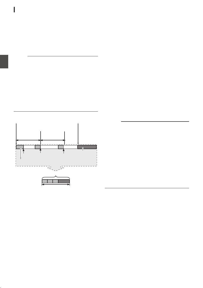
Interval Rec
In normal recording, when the recording stops, the
image and accompanying data from the start till the
end of the recording are recorded as one “clip” on
the SD card.
In this mode, recording and pause are performed
repeatedly at the specified time interval. Only the
specified number of frames is recorded.
The recording can be written to the media as a
single clip until it is stopped.
Memo :
0
Audio will not be recorded.
0
Until a specified amount of recordings is
accumulated, the file will not be written to the
media.
0
After the specified number of frames is recorded
and written to the media, recording will be
performed until the same number is
accumulated again.
0
If the specified amount is not reached when
recording is stopped, normal recording is
performed and frames are added to the ending
of the clip until the amount is reached. (Padding)
.
Specific amount of data
Actual clips recorded to the media
Records number of frames specified in [Rec Frames]
(Padding data)
Normal recording
PausePausePause
[Rec Interval][Rec Interval]
Recording resumes
Recording resumes
(Interval Rec stops)(Interval Rec starts)
Press [REC]Press [REC]
1
Set [Rec Mode] to “Interval Rec”.
0
Set [Main Menu] B [System] B [Record
Set] B [Rec Mode] to “Interval Rec”.
(A P135 [ Rec Interval ] )
0
The display changes (“STBY” B “STBYN”).
2
Set the number of frames to record in [Rec
Frames].
Set using [Main Menu] B [System] B [Record
Set] B [Rec Mode] B [Rec Frames].
(A P135 [ Rec Frames ] )
3
Set the time interval to start recording in
[Interval Rec].
Set using [Main Menu] B [System] B [Record
Set] B [Rec Mode] B [Rec Interval].
(A P135 [ Rec Interval ] )
4
Start recording.
0
Press the [REC] button to record only the
number of frames specified in [Rec
Frames] and pause.
0
After the specified time in [Rec Interval] has
passed, recording starts again to record only
the number of frames specified in [Rec
Frames] and pause.
0
Interval Rec continues until the recording is
stopped.
The display changes (“STBYN” B “RRECN”
B “STBYN” (red text) B “RRECN” B
“STBYN” (red text)).
0
The card slot status indicator blinks in green.
5
Press and hold the [REC] button.
0
The card slot status indicator lights up in
green.
0
The display becomes “STBYN”.
Caution :
0
Do not remove the SD card during recording
(RRECN, red text) or recording pause (STBYN,
yellow text).
0
To remove the SD card during Interval Rec,
press the [CANCEL] button, check that “STBYN”
(white text) is displayed and the card slot status
indicator lights up in green before you remove
the card.
0
When the [TC GENE.] switch inside the door of
the LCD monitor is set to “FREE”, the time code
is recorded in the “Rec Run” mode.
0
Audio cannot be recorded. The audio level
meter is grayed out.
(A P147 [Audio Level Meter] )
92
Special Recording
Shooting
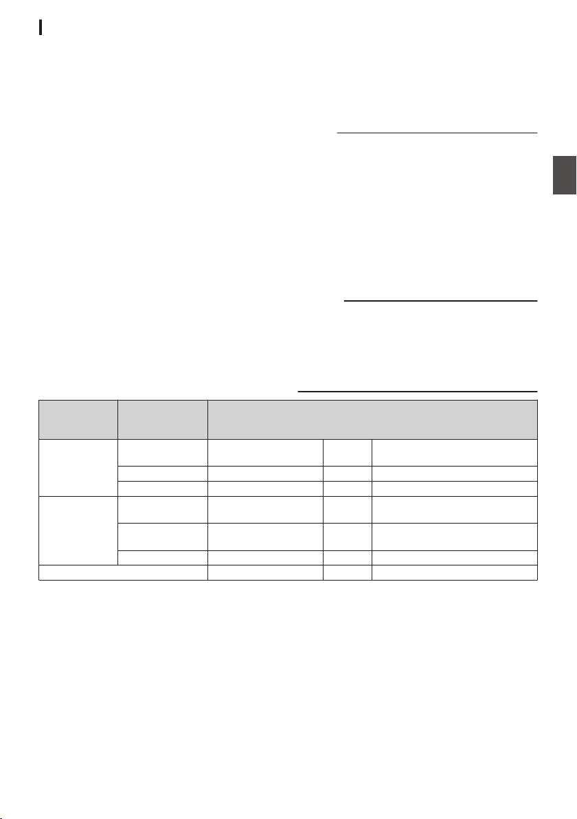
Variable Frame Rec
Shooting in this mode allows you to obtain smooth
slow motion or quick motion videos.
Using different frame rate settings for recording
and playback, videos captured at normal speed
can be played back more smoothly than those in
low or high speed playback.
Th ability to change the frame rate during recording
enables quick to gradually slow motion effects.
To enable Variable Frame Rec, the following
settings are required.
0
[Record Format] B [System] has been set to
“HD”.
0
[Record Format] B [WResolution] is set to
“1920x1080” or “1280x720”.
0
The frame rate in [Record Format] B [WFrame
& Bit Rate] is set to “30p”, “25p”, or “24p”.
1
Set the various items in [Record Format].
(A P132 [ Record Format ] )
2
Set [Rec Mode] to “Variable Frame”.
(A P135 [ Rec Mode ] )
Set [Main Menu] B [System] B [Record Set] B
[Rec Mode] to “Variable Frame”.
3
Set a [Variable Frame Rate].
(A P135 [ Variable Frame Rate ] )
Select a recording frame rate in [Main Menu] B
[System] B [Record Set] B [Rec Mode] B
[Variable Frame Rate].
The selectable frame rates are as shown in the
table below.
Memo :
0
When [Main Menu] B [Camera Function] B [AE
LEVEL SW] is set to “AE LEVEL/VFR”, you can
use the cross-shaped button (HI) to select the
frame rate during Variable Frame Rec. In modes
other than Variable Frame Rec, the cross-
shaped button (HI) functions as the AE level
setting button.
(A P109 [ AE Level ] )
0
If the specified amount is not reached when
recording is stopped, normal recording is
performed and frames are added to the ending
of the clip until the amount is reached. (Padding)
Caution :
0
When the [TC GENE.] switch inside the door of
the LCD monitor is set to “FREE”, the time code
is recorded in the “Rec Run” mode.
0
Audio cannot be recorded. The audio level
meter is grayed out.
(A P147 [Audio Level Meter] )
[WResolution]
Frame Rate of
[WFrame & Bit
Rate]
Selectable Shooting Frame Rate
1920x1080 (*1) 30p - 30 27, 25, 24, 22.5, 20, 18, 15, 12, 10,
6, 2
24p 30, 27, 25 24 22.5, 20, 18, 15, 12, 10, 6, 2
25p - 25 24, 22.5, 20, 18, 12.5, 10, 6, 2
1920x1080 (*2)
1280x720 (*3)
30p 60, 54, 50, 48, 45, 40,
36, 32
30 27, 25, 24, 22.5, 20, 18, 15, 12, 10,
6, 2
24p 60, 54, 50, 48, 45, 40,
36, 32, 30, 27, 25
24 22.5, 20, 18, 15, 12, 10, 6, 2
25p 50, 48, 45, 40, 36, 32 25 24, 22.5, 20, 18, 12.5, 10, 6, 2
Effect during playback Slow motion Standard Quick motion
*1 When [WFormat] is set to MP4 (MPEG2), QuickTime (MPEG2) or MXF (MPEG2)
*2 When [WFormat] is set to QuickTime (H.264)
*3 When [WFormat] is set to MP4 (MPEG2) or QuickTime (MPEG2)
Special Recording
93
Shooting

Playing Recorded Clips
To play back clips recorded on SD cards, switch to
the Media mode.
Press and hold the [CAM/MEDIA] selection button
in the Camera mode to enter the Media mode. A
thumbnail screen of the clips recorded on the SD
card is displayed.
You can play back the selected clip on the
thumbnail screen.
Memo :
0
When an SD card without any clips is inserted,
“No Clips” is displayed.
Operation Buttons
Use the operation buttons, on the side control
panel of the camera recorder or the LCD monitor,
to operate the thumbnail screen.
.
A
D
F G H
I
B
E
D
C
E
A
[MENU/THUMB] Button
0
Displays the menu.
0
Press this button to close the menu screen
during menu display and return to the
thumbnail screen.
B
[DISPLAY] Button
Switches between the “Standard Screen” and
“Detailed Screen”.
C
[CANCEL] (Stop) Button
Cancels settings and returns to the previous
screen.
D
Cross-Shaped Button (JKHI)
Moves the cursor.
E
Set (Play) Button
0
Sets the values and items. (Confirm)
0
Plays back the selected clip.
F
[OIS/1] Button
0
Switches the OK mark of the clip selected by
the cursor.
0
If an OK mark has been appended, it will be
deleted. Otherwise, an OK mark will be
appended.
G
[MARKER/2] Button
0
Switches the selection status of the clip
selected by the cursor.
0
Clips being selected are displayed with
check mark.
H
[LOAD FILE/3] Button
Enters the action selection screen.
I
[STATUS] Button
Displays the media information screen.
Thumbnail Screen
0
“Standard Screen” and “Detailed Screen” are
available.
Use the [DISPLAY] button to switch between the
screens.
0
Thumbnails are displayed in order of recording
from the oldest to most recent.
Standard screen
.
218G0005
A
J
H
C
B
G
E
D
F
I
K
Jan 7, 2014 07:08:43PM
Actions
Select
OK Mark
A
SD Card Information
0
Displays the status of the inserted SD card,
selected SD card, write-protect switch, and
the need for restoring.
0
Use the [SLOT SELECT] button to switch the
slot. Clips in slot A and B cannot be displayed
at the same time.
W z
:
Write-protect switch of the SD card
in slot A is set.
S
:
SD card in slot B needs to be
restored or formatted, or is an
unsupported SD card.
B
Clip Mark
Displays the clip information (properties).
.
A
B
D
E
C
A
OK Mark
Clip is appended with OK mark.
94
Playing Recorded Clips
Playback

Memo :
0
Clips appended with OK marks cannot be
deleted on the camera recorder.
0
When [Main Menu] B [System] B [Record Set]
B [Record Format] B [WFormat] is set to
“AVCHD”, the OK mark indicates that the clip is
protected.
(A P133 [ W Format ] )
B
Continued From Mark
This mark indicates that the current clip is
continued from another SD card when
recording is divided and made on several SD
cards.
C
Uneditable Mark
0
This mark indicates that an OK mark cannot
be appended to or deleted from the clip, and
the clip cannot be deleted.
0
When [Main Menu] B [System] B [Record
Set] B [Record Format] B [Format] is set to
“AVCHD”, clips that are not recorded on this
camera recorder cannot be edited.
0
When [Main Menu] B [System] B [Record
Set] B [Record Format] B [WFormat] is set
to “AVCHD”, clips that are not recorded on
this camera recorder cannot be edited.
D
Continue Mark
This mark indicates that the current clip is
continued onto another SD card when
recording is divided and made on several SD
cards.
E
Check Mark
0
A green check mark is displayed when the
clip is selected.
0
Magenta and gray check marks are
displayed in multiple selection mode.
(A P100 [Selecting and Performing
Operations on Multiple Clips] )
C
Cursor
Clip to be worked on. Use the cross-shaped
button (JKHI) to move the cursor.
D
Thumbnail Substitution Display
.
A B
A
A clip with corrupted management information.
It cannot be played back even if you press the
Set (Play) button.
B
A clip that cannot be played back nor displayed
in thumbnail with the current video format
settings.
It cannot be played back even if you press the
Set (Play) button.
Memo :
0
Dependent on the settings for [Main Menu] B
[System] B [Record Set] B [Record Format] B
[System], [WResolution]/[YResolution], and
[WFrame & Bit Rate]/[YFrame & Bit Rate].
(A P132 [ System ] )
(A P133 [ W Frame & Bit Rate ] )
0
When [Record Format] B [WFormat] is set to
“AVCHD”, playback may fail if the files are
recorded on camera recorders other than the
GY-HM890, GY-HM850, GY-HM650 and
GY-HM600 series.
If a file cannot be played back, the above
thumbnail substitution display 2 is displayed.
E
Clip Name
The file name (clip number) of the selected clip
is displayed.
F
Operation Guide
0
Displays a guide for the current operation
buttons.
0
The action selection screen is displayed
when the User 3 ([LOAD FILE/3]) button is
pressed.
(A P96 [Actions] )
G
Recording Start Time
Displays the recording start time of the clip.
Memo :
0
The date/time display is dependent on the [LCD/
VF] B [Display Settings] B [Date Style]/[Time
Style] settings in the [Main Menu] screen.
(A P124 [ Date Style ] )
(A P124 [ Time Style ] )
H
Scroll Bar
0
Indicates the scroll position.
0
Black space below the scroll bar (white)
indicates that there are more pages.
0
When the scroll bar (white) is at the bottom,
this indicates the last page.
I
Remaining Battery Power
(A P32 [Power Status Display] )
J
Number of Clips
0
If none of the clips are selected, the “running
number/total number of clips” of the clip to be
displayed appears.
0
Even if only one clip is selected, the number
of selected clips in the current slot is
displayed.
K
Network Connection Icon
0
When [Main Menu] B [System] B [Network]
is set to “On(SDI Off)” or “On(HDMI Off)”, the
network connection status is displayed.
This icon is not displayed when “Off” is
selected.
(A P149 [Network Connection Icon] )
Playing Recorded Clips
95
Playback
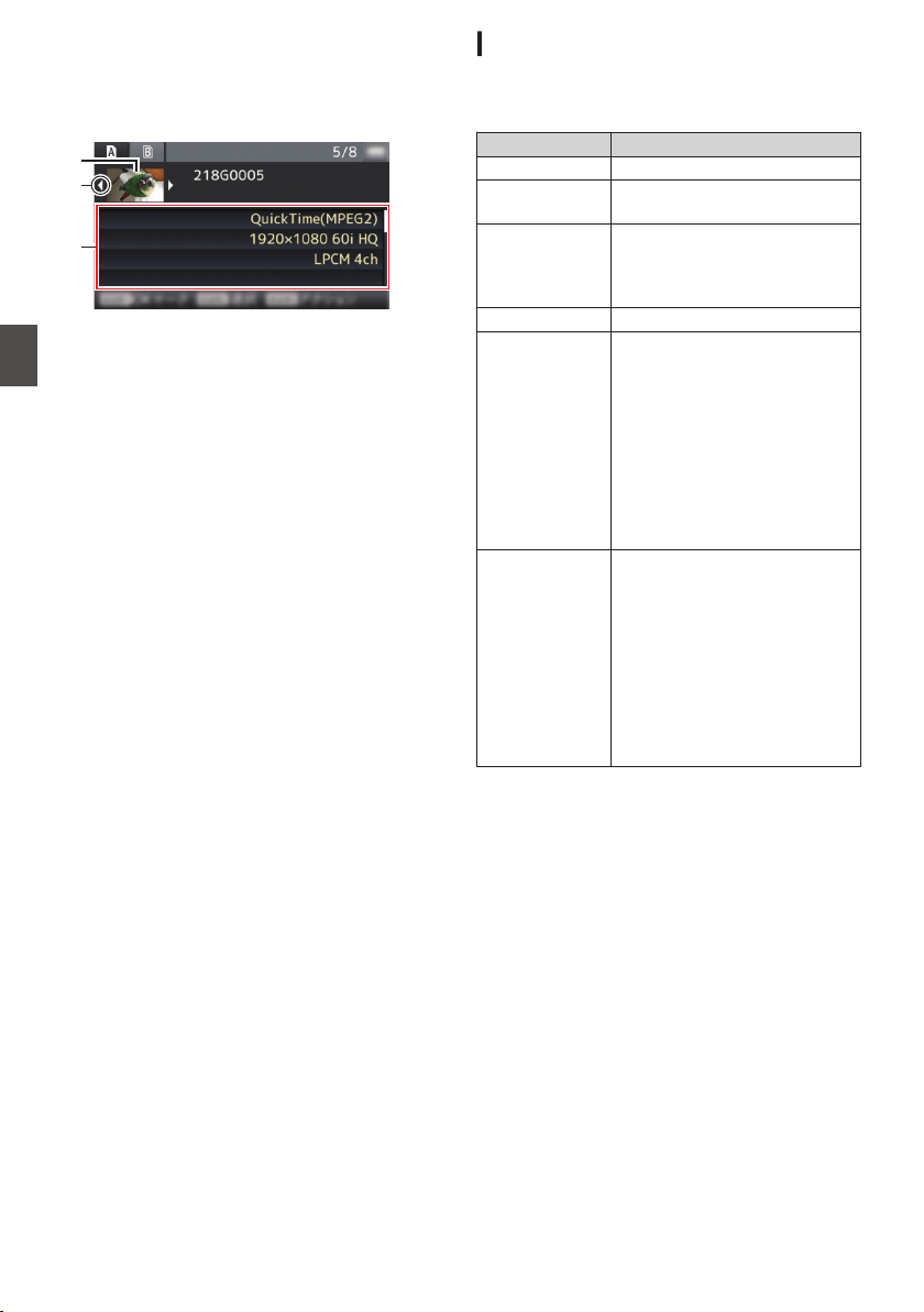
Detailed screen
* Items that are common with the Standard screen
will not be described. Refer to “[Standard
screen] P 94”.
.
C
B
A
Jan 7, 2014 07:08:43PM
Normal
Rec Mode
Audio
Video
Format
A
Thumbnail
Thumbnail of the clip selected by the cursor.
Use the cross-shaped button (HI) to move the
cursor.
B
Scroll Mark (DE)
0
If there are previous clips, D appears on the
left.
0
If there are more clips, E appears on the
right.
0
The marks will not be displayed if there are
no clips before and after the current clip.
C
Metadata
Metadata of the clip pointed by the cursor.
You can use the cross-shaped button (JK) to
scroll.
Actions
The action selection screen is displayed when the
User 3 ([LOAD FILE/3]) button is pressed.
The following operations can be performed.
Item Description
Select All Clips Selects all clips.
Select OK
Marked
Selects all clips appended with
OK mark.
Select Range Specifies the range when
selecting multiple clips.
(A P101 [Selecting Multiple
Clips Consecutively] )
Deselect All Clears all clip selections.
Add OK Mark Appends an OK mark.
0
This Clip:
Appends an OK mark to the
clip pointed by the cursor.
0
Selected Clips:
Appends an OK mark to the
clips selected (appended
with check mark).
0
All Clips:
Appends an OK mark to all
clips.
Delete OK Mark Deletes the OK mark.
0
This Clip:
Deletes the OK mark of the
clip pointed by the cursor.
0
Selected Clips:
Deletes the OK mark of the
clips selected (appended
with check mark).
0
All Clips:
Deletes the OK mark of all
clips.
96
Playing Recorded Clips
Playback
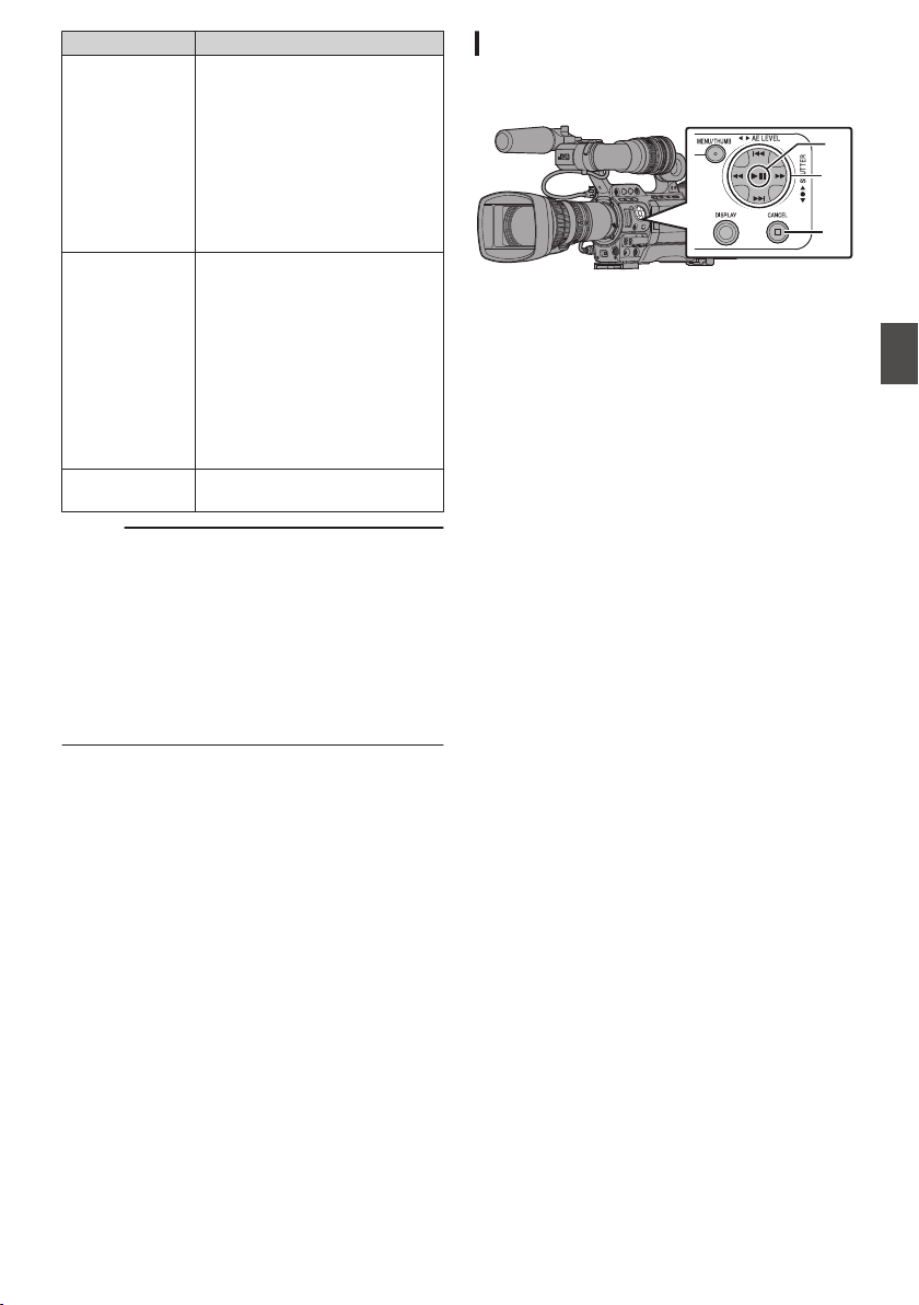
Item Description
FTP Upload Uploads a clip to the FTP server.
0
This Clip:
Uploads the clip pointed by
the cursor.
0
Selected Clips:
Uploads the clips selected
(appended with check
mark).
0
All Clips:
Uploads all clips.
Delete Clips Deletes clip. However, clips with
OK mark cannot be deleted.
0
This Clip:
Deletes the clip pointed by
the cursor.
0
Selected Clips:
Deletes the clips selected
(appended with check
mark).
0
All Clips:
Deletes all clips.
Trim This Clip Trims the clip pointed by the
cursor.
Memo :
0
The object of action is the clip of the current slot
being displayed.
0
[Selected Clips] cannot be performed if there are
no selected (appended with check mark) clips.
0
[This Clip] cannot be performed if there are more
than one selected (appended with check mark)
clips.
0
If the write-protect switch of an SD card is set,
OK mark cannot be appended or deleted, and
the clips cannot be deleted.
Playing back
Use the operation buttons on the side control panel
of the camera recorder to play back.
.
B
C
A
A
IW Button
0
Plays back/pauses the clip pointed by the
cursor.
0
You can press the cross-shaped button (HI)
to perform frame-by-frame forward playback
during pause mode.
B
S/T Button
Skips in the reverse or forward direction.
O/N Button
During Playback:
Fast forwards in the reverse or forward
direction.
While paused:
Frame-by-frame playback in the reverse or
forward direction.
C
o Button
Stops playback.
1
In the thumbnail screen, move the cursor to
the clip to be played back.
Move the cursor to the clip to be played back
using the cross-shaped button (JKH I).
2
Press the playback/pause button.
Playback of the selected clip starts.
Audio Output during Playback
0
You can check the playback sound from the
monitor speaker or the earphone connected to
the [PHONES] terminal. When a earphone is
connected to the [PHONES] terminal, sound
cannot be output from the monitor speaker.
(A P163 [Connecting a Earphone] )
0
Adjust the volume of the monitor speaker and
earphone using the [MONITOR +/-] volume
adjustment button on the LCD monitor of the
camera recorder.
Playing Recorded Clips
97
Playback
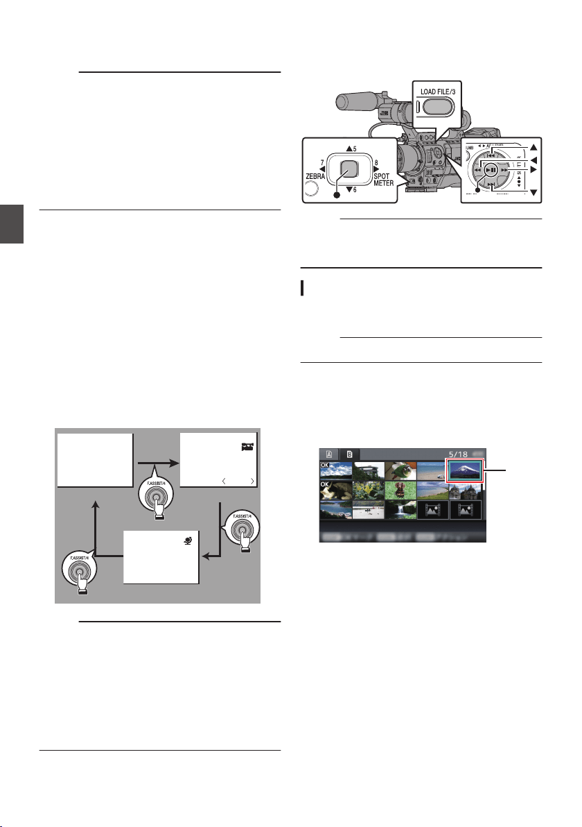
Time Code Playback
Time code or user’s bit recorded on an SD card can
be displayed on the LCD monitor and viewfinder.
Memo :
0
The time code is also superimposed on the
video signal output from the [HD/SD SDI] output
terminal.
0
User’s bit output from the [HD/SD SDI] output
terminal is used as a flag to determine valid
video signals. Therefore, accurate values will
not be output.
0
If a section without time code is played back, the
time code will stop. However, playback will
continue.
Displaying Information during Shooting
Pressing the [DISPLAY] button during playback
displays the display screen.
Pressing the [F.ASSIST/4] button each time
changes the shooting information displayed (not
displayed, camera information display, GPS
display).
0
The GPS display displays information on the
recording location of the video being played
back only when GPS information has been
recorded.
The local date/time is displayed.
0
Camera information display displays only
information of Gain, Iris, Shutter and White
Balance that have been recorded.
.
P13000K
1/100
F1. 6
0dB
+35.483197
+139.652172
Oct 30,2014
07:01:58PM
GPS Display
Camera Information Display
Hide
Memo :
0
When [System] B [Record Set] B [Record
Format] B System is set to “HD+SD” or “HD
+Web”, only SD or web files can be played back
from slot B.
In this case, files up-converted into the HD size
are played back in the simple mode.
0
Trimming information is displayed while
trimming is in progress. In this case, pressing the
[F.ASSIST/4] button does not switch the display.
Deleting Clips
Delete clip.
.
Memo :
0
Clips appended with OK marks cannot be
deleted on the camera recorder.
0
Read-only clips can be deleted on a PC.
Deleting One Clip
Delete the clip (one clip) pointed by the cursor in
[Delete Clips] B [This Clip] in the menu.
Memo :
0
Clips with OK mark cannot be deleted.
During Thumbnail Screen
1
Move the cursor to the clip to be deleted.
Move the cursor to the clip to be deleted using
the cross-shaped button (JKH I).
.
218G0005
1
Jan 7, 2014 07:08:43PM
2
Press the [LOAD FILE/3] button.
The action selection screen is displayed.
98
Playing Recorded Clips
Playback
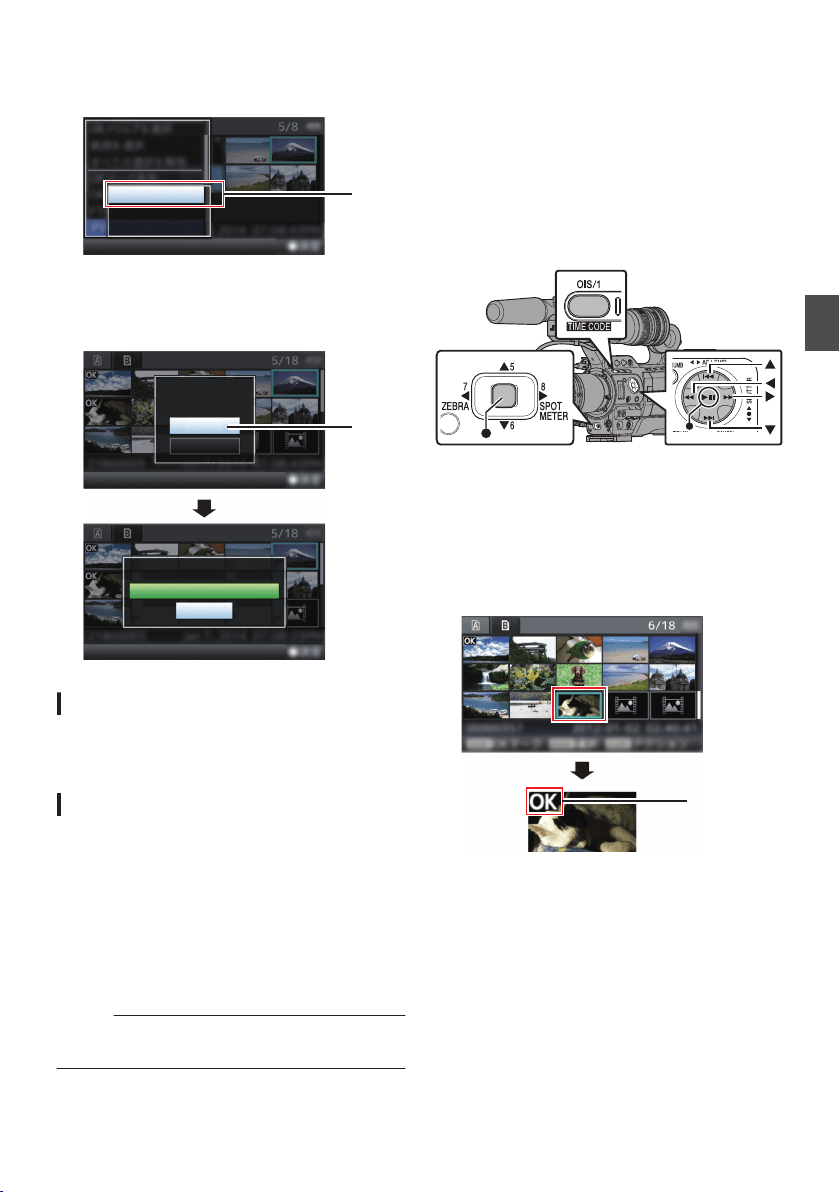
3
Select [Delete Clips]
B [This Clip] and press
the Set button (
R).
A screen to confirm deletion appears.
.
3
All Clips
Selected Clips
This Clip
4
Select [Delete] using the cross-shaped
button (
JK), and press the Set button (R).
Deleting starts.
.
4
Stop
Deleting...
Cancel
Delete
Delete This Clip?
Selecting and Deleting Multiple Clips
To select and delete multiple clips, refer to
“[Selecting and Performing Operations on Multiple
Clips] P 100”.
Deleting All Clips
Delete all clips that are displayed.
1
Press the [LOAD FILE/3] button.
The action selection screen is displayed.
2
Select [Delete Clips]
B [All Clips].
A screen to confirm deletion appears.
3
Select [Delete] and press the Set button
(
R).
Deleting starts.
Memo :
0
The time taken to delete clips depends on the
number of clips to be deleted.
Appending/Deleting OK
Mark
0
You can append OK marks to the clips for
important scenes.
0
Clips appended with OK marks cannot be
deleted, thus protecting the important clips.
0
When the camera recorder is in Media mode,
you can delete the OK marks appended during
recording, or append/delete OK marks after
shooting.
.
During Thumbnail Screen
1
Press the [OIS/1] button.
0
If the clip does not have an OK mark, an OK
mark will be appended.
0
If the clip is appended with an OK mark, the
OK mark will be deleted.
.
OK Mark
Deleting Clips
99
Playback
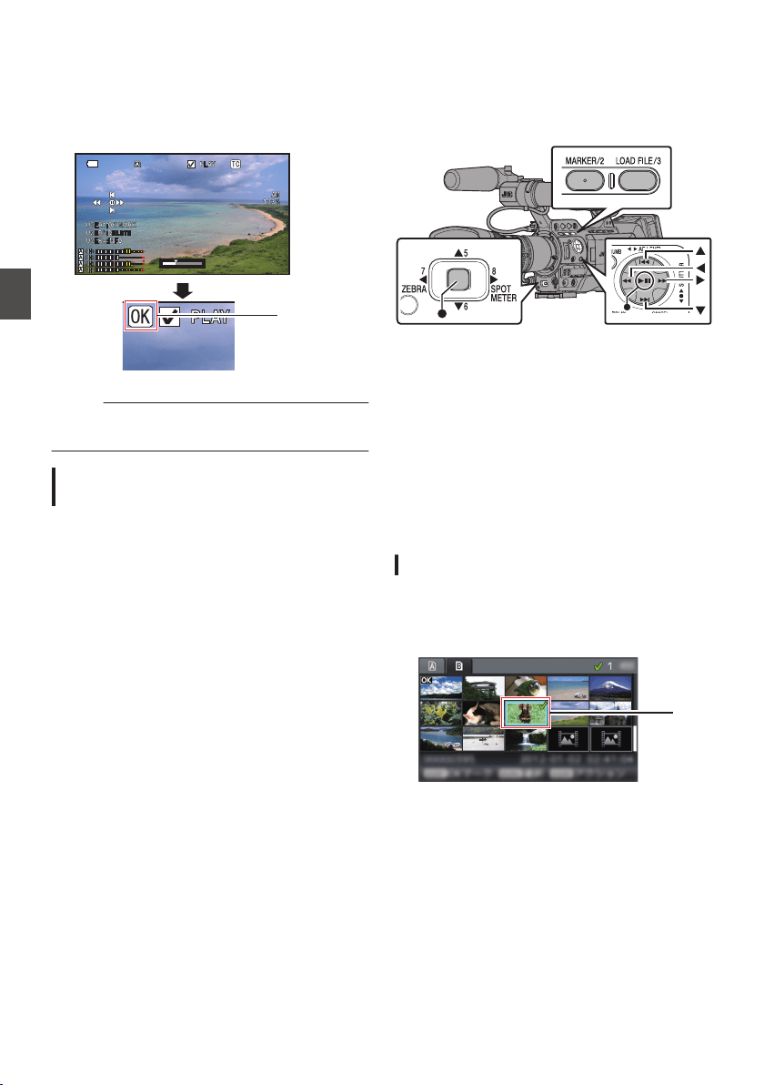
During Playback or Pause Screen
1
Press [OIS/1] button during clip playback.
0
If the clip does not have an OK mark, an OK
mark will be appended.
0
If the clip is appended with an OK mark, the
OK mark will be deleted.
.
00
12:34:56
12:34:56
Jan 24,2014
Jan 24,2014
00:00:00.00
00:00:00.00
x5
x5
x5
x5
60i
60i
1920x1080
1920x1080
16.4V
16.4V
2/4
2/4
XHQ
XHQ
OK Mark
Memo :
0
The clip pauses when an OK mark is appended
or deleted during playback.
Appending/Deleting OK Mark of
Multiple Clips
To select and append/delete OK mark for multiple
clips, refer to “[Selecting and Performing
Operations on Multiple Clips] P 100”.
Selecting and Performing
Operations on Multiple
Clips
.
0
Multiple clips can be selected during thumbnail
screen or playback screen display.
0
After selecting multiple clips, perform
appending/deleting of OK mark, deleting of clips
using the action selection screen.
0
After selecting multiple clips, the selections will
be canceled by the following operations.
0
When [Deselect All] in the action menu is
selected
0
When exiting Media mode from the thumbnail
screen
0
When removing the SD card
0
When switching the slot in use
Selecting Multiple Clips Randomly
1
Move the cursor to a clip without a check
mark, and press the [MARKER/2] button.
A green check mark appears on the clip.
.
1
100
Appending/Deleting OK Mark
Playback
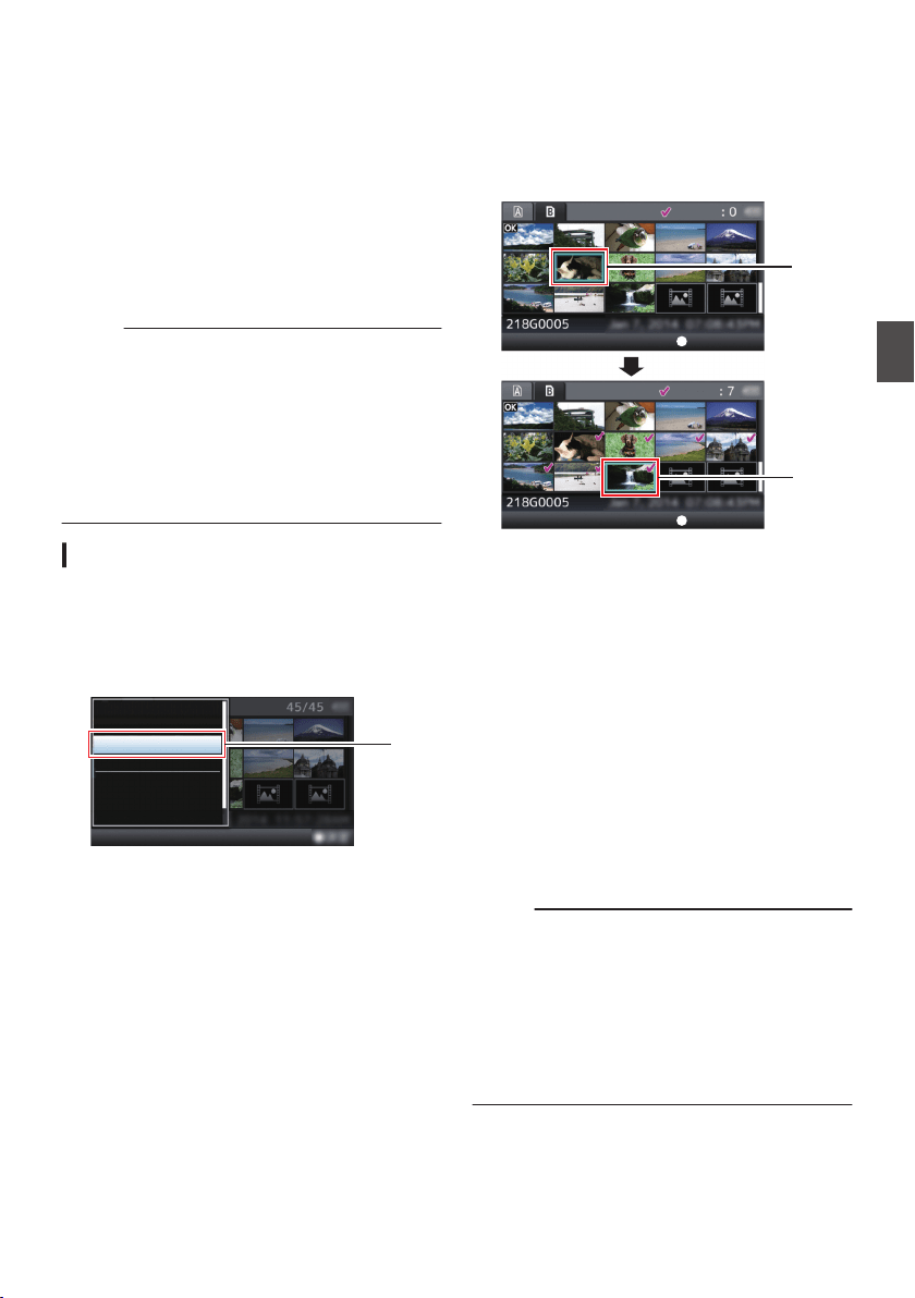
2
Repeat Step
1 to select multiple clips.
0
Multiple clips can be selected.
0
Press the [LOAD FILE/3] button while the
multiple clips are selected.
0
Appends OK mark together:
[Add OK Mark] B [Selected Clips]
0
Deletes OK mark together:
[Delete OK Mark] B [Selected Clips]
0
Uploading selected clips to the FTP server
together:
[FTP Upload] B [Selected Clips]
0
Deletes selected clips together:
[Delete Clips] B [Selected Clips]
Memo :
0
Selecting clips appended with check mark and
pressing the [MARKER/2] button will cancel the
selection.
0
If the operation is performed on multiple clips at
the same time, a progress bar appears. You can
stop the operation by pressing the Set button (R)
while the operation is in progress. However, it is
not possible to undo operations that are
completed.
Selecting Multiple Clips Consecutively
1
Press the [LOAD FILE/3] button.
2
Select “Select Range” in the action
selection screen, and press the Set button
(
R).
.
FTP Upload...
Delete OK Mark...
Add OK Mark...
Deselect All
Select Range
Select OK Marked
Select All Clips
2
3
Move the cursor to the beginning (or end)
of the range for multiple selection, and
press the Set button (
R).
4
Move the cursor to the other end of the
range.
0
Magenta check marks appear on the clips
within the range. (Including clips that were
already selected.)
0
Gray check marks appear on selected clips
that are outside the range.
.
3
4
Selected Range:
Selected Range:
End Position
Start Position
5
Press the Set button (
R) to confirm the
range.
0
The check marks change from magenta to
green.
0
Pressing the [LOAD FILE/3] button while the
multiple clips are selected displays the
action selection screen. The following
operations can be performed.
0
Appends OK mark together:
[Add OK Mark] B [Selected Clips]
0
Deletes OK mark together:
[Delete OK Mark] B [Selected Clips]
0
Uploading selected clips to the FTP server
together:
[FTP Upload] B [Selected Clips]
0
Deletes selected clips together:
[Delete Clips] B [Selected Clips]
Memo :
0
Selecting clips appended with check mark and
pressing the [MARKER/2] button will cancel the
selection.
0
If the operation is performed on multiple clips at
the same time, a progress bar appears. You can
stop the operation by pressing the Set button (R)
while the operation is in progress. However, it is
not possible to undo operations that are
completed.
Selecting and Performing Operations on Multiple Clips
101
Playback
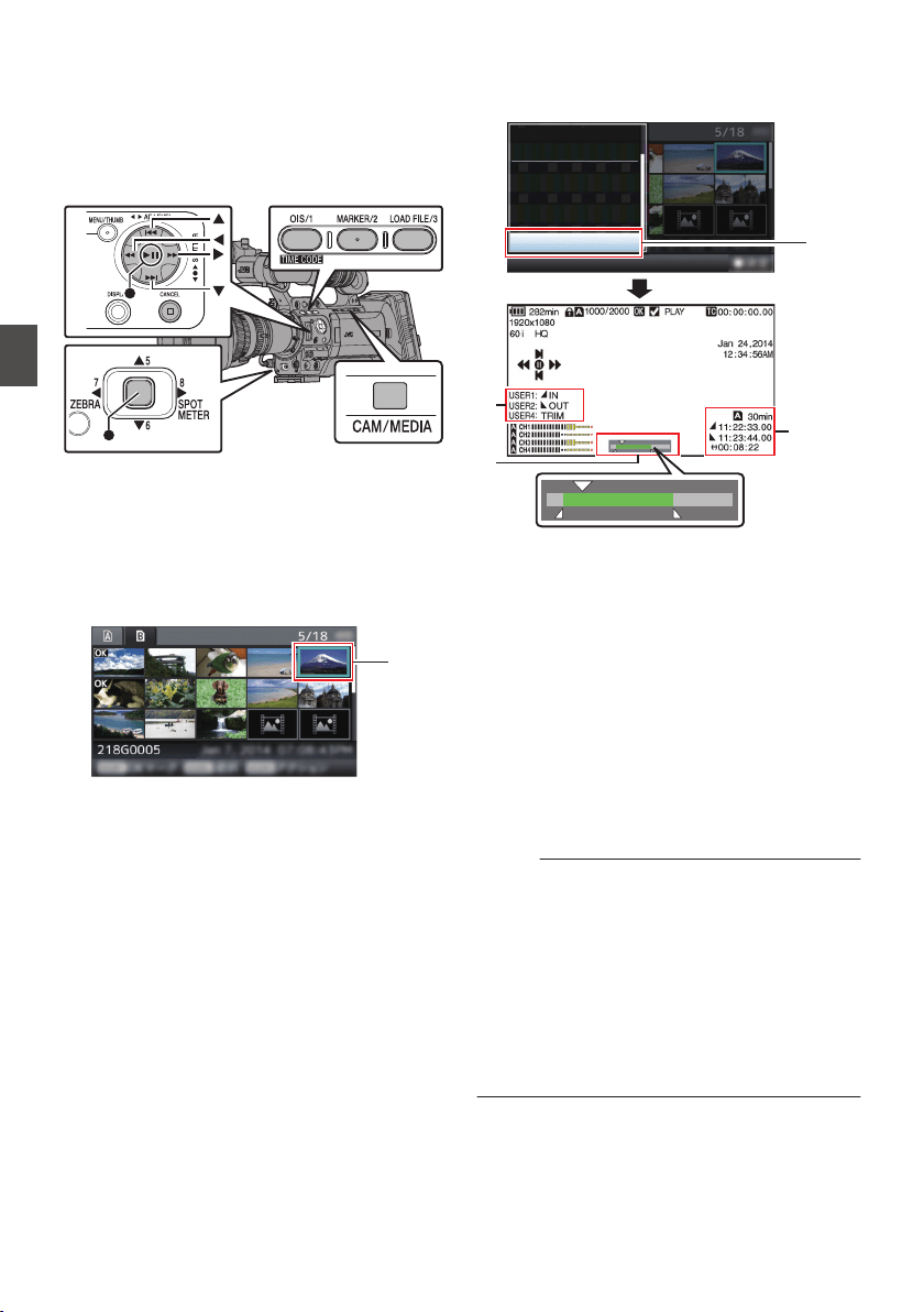
Trimming Recorded Clips
You can extract (trim) the necessary parts of a clip
recorded in the SD card.
The trimmed clip is saved as a new file on the same
SD card as the original clip. No changes are made
to the original clip.
.
1
Switch to Media mode.
Switch the mode using the [CAM/MEDIA]
selection button on the side operation panel.
2
Move the cursor to the clip to be trimmed.
Move the cursor to the clip to be trimmed using
the cross-shaped button (JKH I).
.
2
3
Press the [LOAD FILE/3] button.
The action selection screen is displayed.
4
Select [Trim This Clip], and press the Set
button (
R).
Playback of the selected clip starts.
.
A
B
C
4
Trim This Clip
Delete Clips...
FTP Upload...
Delete OK Mark...
Add OK Mark...
Deselect All
Select Range
A
Guide
Operation guide
B
Position bar
6
: Current position of the video
7
: Position to start trimming (in point)
8
: Position to end trimming (out point)
C
Trimming information
W or Y : Indicates the available space
in the storage media (W or Y)
7
: Indicates the time code of the
in point
8
: Indicates the time code of the
out point
9
: Indicates the duration from the
in point to the out point
Memo :
0
The trimmed clip will be saved to the same card
slot as that of the original clip.
0
[Duration] appears in yellow if the duration is 10
minutes or longer. Trimming cannot be
performed in this case.
0
[Duration] appears in yellow if the duration is
longer than the recordable time on the storage
media. Trimming cannot be performed in this
case.
0
When trimming starts, the display switches to
the Media Display 2 screen.
102
Trimming Recorded Clips
Playback
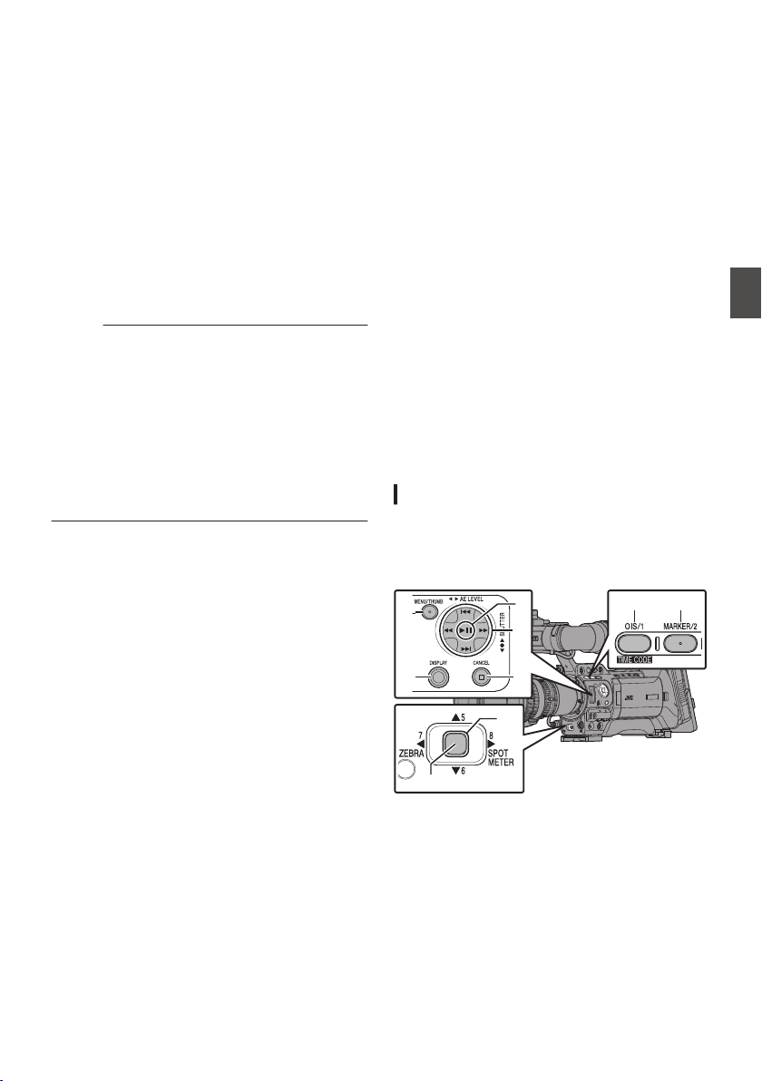
5
Specify the in point.
0
Operate buttons such as O/N or S/T
to move the video to the in point.
(A P97 [Playing back] )
0
Specify the in point by pressing the [OIS/1]
button at the point you want to start trimming.
6
Specify the out point.
0
Operate buttons such as O/N or S/T
to move the video to the out point.
(A P97 [Playing back] )
0
Specify the out point by pressing the
[MARKER/2] button at the point you want to
end trimming.
7
Perform trimming.
Press the [LOAD FILE/3] button to perform
trimming.
Memo :
0
While trimming is in progress, you can press the
[CANCEL] button to return to the thumbnail
screen.
0
While trimming is in progress, you can press the
[DISPLAY] button to switch the display, but the
trimming information is displayed at all times.
0
When trimming the in and out point, the in point
trimmed may be up to one second before the
specified in point and the out point trimmed may
be up to one second behind the specified out
point.
Basic Operations in Menu
Screen
0
Press the [MENU/THUMB] button on the side
control panel of the camera recorder or on the
LCD monitor to display the menu screen on the
LCD monitor and viewfinder.
0
Various settings for shooting and playback can
be configured on the menu screen.
0
There are two types of menu screens - [Main
Menu] and [Favorites Menu].
0
[Main Menu] contains all the setting items of the
camera recorder, classified according to
functions and uses, while [Favorites Menu]
allows users to customize the menu items freely.
(A P142 [Adding/Editing Frequently Used
Menu Items] )
0
The operating procedures and main screen
displays are the same for both menus.
0
The menu screen can also be displayed on
external monitors connected to the video signal
output terminal.
(A P126 [ HDMI Out Character ] )
(A P126 [ SDI Out Character ] )
(A P126 [ VIDEO Out Character ] )
Operation Buttons
To operate the menu, use the cross-shaped
buttons on the side operation panel of the camera
recorder or the cross-shaped buttons at the front of
the camera or at the bottom of the lens.
.
A
D
F G
B
E
D
C
E
Trimming Recorded Clips
103
Playback

A
[MENU/THUMB] Button
0
Displays the menu screen. The [Main
Menu] screen is displayed by default.
0
During normal usage, [Main Menu] is
displayed if the previous menu operation
ended at [Main Menu], and [Favorites
Menu] if the previous menu operation ended
at [Favorites Menu].
0
Press this button to close the menu screen
during menu display and return to the normal
screen.
0
Pressing and holding down the button while
the menu is displayed switches the [Main
Menu] screen to the [Favorites Menu] or vice
versa.
B
[DISPLAY] Button
Switches between the [Main Menu] and
[Favorites Menu] screens.
C
[CANCEL] Button
Cancels settings and returns to the previous
screen.
D
Cross-shaped Button (JKH I)
J
: Moves the cursor upward.
K
: Moves the cursor downward.
H
: Moves back to the previous item.
I
: Moves forward to the next item.
E
Set Button (R)
Sets the values and items.
F
[OIS/1] Button
Adds the selected menu or submenu item to the
[Favorites Menu].
(A P142 [Adding/Editing Frequently Used
Menu Items] )
G
[MARKER/2] Button
Resets settings in the [TC Preset] or [UB
Preset] setting screen. This button is disabled
in other screens.
Display and Description of the Menu
Screen
Selecting Menu Items
.
H
I
F
E
B
D
G
A
C
AddFavorites
SEC
Shutter
24hourTime Style
YMDDate Style
OnDate/Time
TimeBattery
OffAudio Meter
Display Settings
A
Cursor
Indicates the selected item. Use the cross-
shaped button (JK) to move the cursor
B
Menu Item
0
Displays the names of the menu item and
sub-menu.
0
Menu items with [...] after them indicates that
there is a sub-menu to access.
C
Fixed Item
Items that cannot be changed are displayed in
gray and cannot be selected.
D
Operation Guide
Guide for the current operation buttons.
E
Setting Value
Setting values for the menu items.
For menus with sub-menus, values are not
displayed.
F
Scroll Bar
Indicates the scroll position.
G
Header
Indicates the current menu type with the line
color.
Blue : [Main Menu] Screen
Green : [Favorites Menu] (Operation
screen)
Magenta : [Favorites Menu] (Editing screen)
H
Remaining Battery Power
(A P32 [Power Status Display] )
Memo :
0
If the recommended battery (or equivalent
battery sold separately) is not used, the battery
mark which indicates the battery level may not
appear.
I
Menu Title
Title of the currently displayed menu.
104
Basic Operations in Menu Screen
Menu Display and Detailed Settings
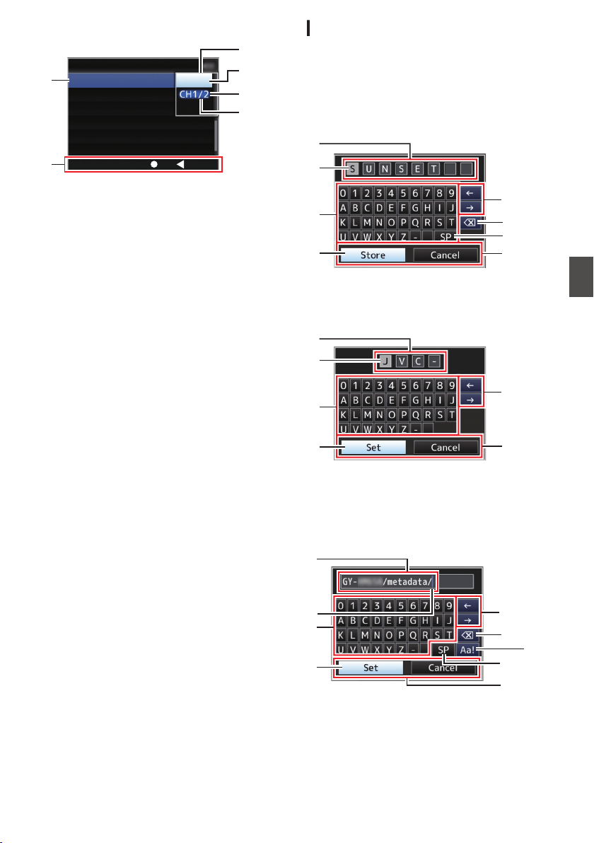
Changing Setting Values
.
D
F
A
C
B
E
CancelSet
Off
Auto
SECShutter
24hourTime Style
YMDDate Style
Date/Time
Battery
Audio Meter
Display Settings
A
Menu Item to Change
Menu item to be changed.
A list of setting values F appears in a pop-up.
B
Operation Guide
Guide for the current operation buttons.
C
Setting Values Before Change
Setting values before changing. The
background of the item is displayed in blue.
D
Scroll Bar
Indicates the scroll position.
E
Cursor
Indicates the selected item. Use the cross-
shaped button (JK) to move the cursor
F
List of Setting Values
0
A pop-up displaying a list of setting values for
selection.
0
The height of the pop-up depends on the
number of settings available. Use the scroll
bar D to confirm the current display status.
Text Input with Software Keyboard
For entering the subname for the setup file,
entering the [Clip Name Prefix], and the settings
under [Network] B [Settings].
Entering a subname
(A P157 [Configuring Setup Files] )
.
G
A
E
H
C
B
D
F
Entering the [Clip Name Prefix]
(A P137 [ Clip Name Prefix ] )
.
A
E
H
C
B
D
Settings under [Network] B [Settings]
The keyboard displayed varies according to the
settings.
(A P137 [Network/Settings Item] )
.
A
H
C
G
D
B
E
F
I
Basic Operations in Menu Screen
105
Menu Display and Detailed Settings

A
Character Entry Field
0
Field for entering the title.
0
You can enter up to 8 characters for the
[Scene File]/[Picture File] subname or up to
4 characters for the [Clip Name Prefix].
B
Character Cursor
Select a character using the key cursor D, and
press the Set button (R) to input the selected
character at the position of the character cursor.
The character cursor moves to the next position
on the right each time a character is input.
The cursor can be moved using the arrow keys
H.
C
Character Keys
Use the cross-shaped button (JKHI) to move
the key cursor D to the character you want to
enter.
D
Key Cursor
Indicates the currently selected character or
item. Use the cross-shaped button (JKHI) to
move the cursor.
E
Confirmation Buttons
0
Select [Set]/[Store] and press the Set button
(R) to confirm the title.
0
Select [Cancel] and press the Set button (R)
on the side control panel of the camera
recorder to abort character input and return
to the previous screen.
F
[SP] Space Key
Select [SP] and press the Set button (R) on the
side control panel of the camera recorder to
enter a space at the current position of the
character cursor B.
G
[3 ] Backspace Key
Select [3 ] and press the Set button (R) on the
side control panel of the camera recorder to
delete the character on the left of the character
cursor B.
H
Arrow Keys
Moves the position of the character cursor B.
I
Character Switch Button
Switches the character buttons C to the upper
case, lower case, and symbols.
About the Menu Lock
Feature
This is a feature for preventing the menu settings
from being altered.
.
1
While in the Camera mode (when the
display screen appears), press and hold
the [CANCEL] and [MENU] buttons at the
same time for 5 seconds or longer.
All menu operations are disabled. Switching
from the display screen to the menu screen is
also disabled.
Memo :
0
Powering off the camera recorder turns off the
menu lock.
106
Basic Operations in Menu Screen
Menu Display and Detailed Settings

Menu Screen Hierarchical
Chart
[Main Menu...] ........................................... P 107
- [Camera Function...] .............................. P 108
- [Bars] ................................................. P 108
- [OIS] .................................................. P 108
- [Flicker Correction] ............................ P 108
- [Flash Band Correction] ..................... P 108
- [Shutter] ............................................. P 108
- [AE Level] .......................................... P 109
- [AE Speed] ........................................ P 109
- [ALC Limit] ......................................... P 109
- [Auto Iris Limit (OPEN)] ..................... P 109
- [Auto Iris Limit (CLOSE)] ................... P 109
- [EEI Limit] .......................................... P 109
- [Smooth Trans] .................................. P 109
- [FAW] ................................................ P 109
- [GAIN L] ............................................. P 109
- [GAIN M] ............................................ P 109
- [GAIN H] ............................................ P 109
- [AE LEVEL SW] ................................. P 109
- [Handle Zoom Speed] ....................... P 110
- [AF Speed] ........................................ P 110
- [AF Assist] ......................................... P 110
- [Remote Func. Change] .................... P 110
- [Lens REC] (*) ................................... P 110
- [User Switch Set...] ............................ P 110
- [FULL AUTO...] .................................. P 110
- [Camera Process...] .............................. P 114
- [Detail] ............................................... P 114
- [Adjust...] ..................................... P 114
- [Master Black] ................................... P 114
- [Black Toe] ........................................ P 114
- [Knee] ................................................ P 115
- [White Clip] ........................................ P 115
- [Gamma] ........................................... P 115
- [WDR] ................................................ P 116
- [White Balance...] .............................. P 116
- [Color Matrix] ..................................... P 116
- [Adjust] ........................................ P 116
- [Color Gain] ....................................... P 116
- [Reverse Picture] ............................... P 116
- [Shooting Mode] ................................ P 117
- [Reset Process] ................................. P 117
- [TC/UB...] .............................................. P 119
- [TC Preset] ........................................ P 119
- [UB Mode] ......................................... P 119
- [Drop Frame] ..................................... P 119
- [LCD/VF...] ............................................ P 120
- [Shooting Assist...] ............................. P 120
- [Marker Settings...] ............................ P 120
- [Display Settings...] ............................ P 120
- [LCD + VF] ......................................... P 120
- [LCD/VF Display] ............................... P 120
- [VF Color] .......................................... P 120
- [VF Contrast] ..................................... P 120
- [LCD Contrast] ................................... P 120
- [LCD Backlight] ................................. P 120
- [LCD Mirror] ....................................... P 120
- [A/V Set...] ............................................. P 125
- [Video Set...] ...................................... P 125
- [Audio Set...] ...................................... P 125
- [System...] ............................................. P 130
- [Record Set...] ................................... P 130
- [Media] .............................................. P 130
- [Setup File] ........................................ P 130
- [Tally System] .................................... P 130
- [Front Tally] ....................................... P 130
- [Back Tally] ........................................ P 130
- [GPS] ................................................. P 130
- [Language] ........................................ P 131
- [Network] ........................................... P 131
- [Settings] ..................................... P 131
- [System Frequency] .......................... P 131
- [Reset All] .......................................... P 131
- [Date/Time] ........................................ P 131
- [Time Zone] ....................................... P 131
- [System Information] .......................... P 132
* Displayed only when KA-F790G is connected
Memo :
0
Some menus cannot be set depending on the operating mode or status of the camera recorder. These
items are displayed in gray, and they cannot be selected.
0
Setting value with the R mark is the factory default.
0
Remotely controlled items are displayed as
and cannot be selected.
Menu Screen Hierarchical Chart
107
Menu Display and Detailed Settings

Camera Function Menu
Menu screen for specifying operation settings
during shooting.
This item can only be selected in the Camera
mode.
Bars
For setting whether to output color bars.
[Setting Values: On, ROff]
Memo :
0
The audio test signals (1 kHz) can be output
simultaneously with the color bar output.
(A P129 [ Test Tone ] )
0
This feature will be set to “Off” automatically if
you switch the camera recorder from the
Camera mode to other modes or set the
[POWER ON/OFF] switch to “OFF”.
OIS F
For setting whether to enable image stabilizer.
When “On” is selected, set the Level.
[Setting Values: On, ROff]
* When the supplied lens is not attached, “---” is
displayed and selection cannot be made.
9
Level
For setting the level of the image stabilizer.
[Setting Values: High, RNormal]
Memo :
0
When “High” is selected, correcting severe
camera shake may cause the area surrounding
the image to darken.
Flicker Correction
For setting whether to adjust image flicker that
occurs under a fluorescent light.
[Setting Values: On, ROff]
Memo :
0
In any of the following cases, “Off” is displayed
and selection cannot be made.
0
During slow shutter
0
When [Rec Mode] is set to “Variable Frame”
0
When the number of frames of [WFrame & Bit
Rate]/[YFrame & Bit Rate] is “24p”
Flash Band Correction
For reducing the condition of the flash band
phenomenon, which creates an unnatural image
with a part of it brightly lit, such as by the camera
flash of another still camera.
[Setting Values: On, ROff]
Caution :
0
Flash band correction function is not available in
any of the following cases.
0
When [Rec Mode] is set to “Variable Frame”
0
When the frame rate of [WFrame & Bit Rate]/
[YFrame & Bit Rate] is “24p”
0
When the shutter speed is set to a value other
than OFF
(A P60 [Manual Shutter Mode (Manual
Shutter Switching)] )
0
When [Network] is set to “On(SDI Off)” or
“On(HDMI Off)”
0
[Flash Band Correction] operates when the
luminance of the screen varies widely, with or
without flash light. However, depending on the
shooting condition, the flash band correction
may not be fully effective even if there are flash
lights.
0
The following symptoms may occur under flash
light, but these are not malfunctions due to flash
band correction.
0
Moving object appears to be stationary
momentarily.
0
A horizontal line appears on the image.
0
The [Flash Band Correction] feature will be set
to “Off” automatically if you switch the camera
recorder from the Camera mode to other modes
or set the [POWER ON/OFF] switch to “OFF”.
Shutter
For specifying shutter-related settings.
Use this item to set to “Step” (fixed value) or
“Variable” when operating with the cross-shaped
button (JK) on the right side.
0
EEI:
Select this to perform automatic control of the
shutter.
0
Variable:
Sets to variable scan. Use this setting such as
when shooting a PC monitor.
0
Step:
Sets to step shutter, which switches the shutter
speed by a fixed value.
[Setting Values: EEI, Variable, RStep]
108
Camera Function Menu
Menu Display and Detailed Settings

AE Level
For setting the convergence level during AE (Auto
Exposure).
This can also be adjusted using the cross-shaped
button (HI) on the right side.
[Setting Values: -6 to +6 (R0)]
Memo :
0
In all the following cases, “---” is displayed and
selection cannot be made.
0
When gain is set to a value other than “ALC”
0
When [Shutter] is set to a value other than
“EEI”
0
When the [IRIS A/M] selection switch is set to
“M” (only when the supplied lens is used)
AE Speed
For setting the convergence speed during AE (Auto
Exposure).
[Setting Values: RFast, Middle, Slow]
ALC Limit
For setting the maximum gain value of “ALC”,
which electrically boosts the sensitivity level
according to the brightness automatically.
[Setting Values: 24dB, R18dB, 12dB, 6dB]
Auto Iris Limit (OPEN)
For setting the limit value of the OPEN end when
auto iris is enabled.
[Setting Values: F5.6, F4, F2.8, F2, F1.6, RF1.4]
Auto Iris Limit (CLOSE)
For setting the limit value of the CLOSE end when
auto iris is enabled.
[Setting Values: RF16, F11, F8, F5.6]
EEI Limit
For setting the shutter speed control range when
the Automatic Shutter mode (EEI) is enabled.
[Setting Values: 4F-stop, R3F-stop, 2F-stop]
Smooth Trans
For setting the shock reduction function, which
slows down the sudden change when switching
with the [GAIN L/M/H] selection switch or
[WHT.BAL B/A/PRESET] switch.
[Setting Values: Fast, Middle, Slow, ROff]
Memo :
0
This feature does not function when the [FULL
AUTO] switch is “ON”, while the [GAIN L/M/H]
selection switch or [WHT.BAL B/A/PRESET]
switch is disabled.
FAW
For setting where to assign the FAW (Full Auto
White Balance) feature in the [WHT.BAL B/A/
PRESET] switch.
[Setting Values: B, A, PRESET, RNone]
Memo :
0
When the [FULL AUTO] switch on the camera
recorder is set to “ON”, and [FULL AUTO] B
[White Balance] is set to “FAW”, the setting is
fixed at “FAW”.
GAIN L/GAIN M/GAIN H
For setting the gain value of each position on the
[GAIN L/M/H] selection switch.
When “ALC” is selected, the camera recorder
switches to the Auto Gain mode.
[Setting Values: ALC, 24dB, 21dB, 18dB, 15dB,
12dB, 9dB, 6dB, 3dB, 0dB, -3dB, -6dB]
(Default values GAIN L: 0dB, GAIN M: 6dB, GAIN
H: 12dB)
Memo :
0
When the [FULL AUTO] switch on the camera
recorder is set to “ON”, and [FULL AUTO] B
[Gain] is set to “ALC”, the setting is fixed at
“ALC”.
AE LEVEL SW
For specifying the operation of the cross-shaped
button (HI) on the right side.
0
AE LEVEL/VFR:
Sets the number of frames during Variable
Frame Rec, and operates as the AE level setting
button in other cases.
(A P93 [Variable Frame Rec] )
0
AE Level:
Operates as the AE level setting button at all
times.
0
Disable:
Disables the button.
[Setting Values: AE LEVEL/VFR, RAE Level,
Disable]
Camera Function Menu
109
Menu Display and Detailed Settings

Handle Zoom Speed F
This function allows you to set the zoom speed of
the zoom lever at the handle when the [ZOOM FIX/
VAR/OFF] switch is set to “FIX”.
[Setting Values: 1 to 8 (R 5)]
* When the supplied lens is not attached, “---” is
displayed and selection cannot be made.
AF Speed F
For setting the AF operation speed.
[Setting Values: Fast, RMiddle, Slow]
AF Assist F
For setting whether to shift the auto focus point
when the focus ring is turned during Auto Focus
(AF).
* When the supplied lens is not attached, “---” is
displayed and selection cannot be made.
0
Area:
This option allows you to shift the auto focus
point to the left, center, right, or near and far
directions by turning the focus ring during AF.
Selecting this option displays the
icon in
the area.
0
Far/Near:
This option allows you to shift the auto focus
point to near and far directions by turning the
focus ring during AF.
[Setting Values: Area, Far/Near, ROff]
(A P54 [AF Assist Function F] )
Memo :
0
This setting is effective only when the [AUTO
FOCUS/11] switch is set to “ON”.
0
The manual focus adjustment mode is
temporarily activated by turning the focus ring in
the AF mode. If the focus ring is not operated for
a certain time, the camera recorder returns to the
AF mode.
Remote Func. Change F
For setting whether to enable focus operation when
performing zooming from a wired remote control.
[Setting Values: Zoom → Focus, ROff]
Memo :
0
This function is effective only if a wired remote
control is connected to the [REMOTE2]
terminal.
Lens REC (Displayed only when KA-F790G is
connected) A B
For setting the function of the [REC] button on the
lens.
0
Intercom:
Functions as an ON/OFF button for headset
calls.
Pressing the button each time toggles headset
call between on/off.
Press and hold down the button to turn on
headset call. Release to turn off.
0
Rec:
Functions as a recording button to start or stop
recording.
[Setting Values: Intercom, RRec]
User Switch Set...
For specifying user button related settings.
(A P111 [User Switch Set Item] )
FULL AUTO...
For setting which feature to set to auto when the
[FULL AUTO] switch on the camera recorder is
“ON”.
(A P113 [FULL AUTO Item] )
110
Camera Function Menu
Menu Display and Detailed Settings
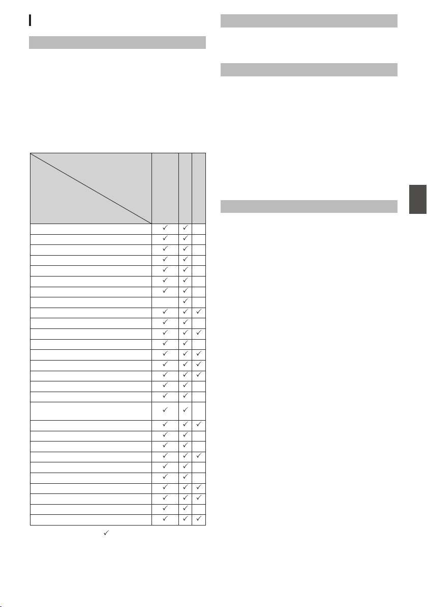
User Switch Set Item
USER1 to USER11, Lens RET
By assigning one of the menu functions below to
the [OIS/1], [MARKER/2], [LOAD FILE/3],
[F.ASSIST/4], [J/5], [K/6], [7/H/ZEBRA], [8/I/
SPOT METER], [AWB/9], [REC/10], [AUTO
FOCUS/11] buttons and the [RET] button on the
lens, you can operate the preset function (on/off,
startup, switching).
Set according to the shooting conditions. Usable
only in the Camera mode.
The settable values for each item are as follows.
.
−
−
−
−
−
−
−
−
−
−
−
−
−
−
−
−
−
−
−
: −:
Settable
Setting Value
Item
Live Streaming
Load Picture File
Return VideoAB
Clip Review
OK Mark
Clip Cutter Trig
Backup Trig
Rec
LCD Backlight
Expanded Focus
Histogram
Spot Meter
Focus Assist
Marker
Zebra
AWB
White Balance
Preset Zoom1 to Preset Zoom3
Auto FocusF
One Push FocusF
One Push IrisF
OISF
Face DetectF
AE Lock
Lolux
Flash Band
Bars
None
Not settable
USER11
USER9, USER10
USER1 to USER8,
Lens RET
Lolux
To increase the sensitivity when in dim
surroundings, set a value in the Lolux mode.
[Setting Values: 36dB, R30dB]
Clip Review
For setting the operation of clip review.
* Clip review functions by operating the user button
assigned with the “Clip Review” function.
0
Last 5sec:
Views about 5 seconds of the clip from the
ending.
0
Top 5sec:
Views about 5 seconds of the clip from the
beginning.
0
Clip:
Views the entire clip.
[Setting Values: RLast 5sec, Top 5sec, Clip]
Spot Meter
For setting the operation of the spot meter.
* Spot meter functions by operating the user button
assigned with the “Spot Meter” function.
(A P80 [Setting Spot Meter] )
0
Max & Min:
Displays the brightest and darkest areas of the
image.
0
Max:
Displays the brightest area of the image.
0
Min:
Displays the darkest area of the image.
0
Manual:
Displays the image brightness at a specified
position.
[Setting Values: RMax & Min, Max, Min, Manual]
Camera Function Menu
111
Menu Display and Detailed Settings

Face Detect F
Select the control to track results of face detection.
* Face Detect functions by operating the user
button assigned with the “Face Detect” function.
* When the supplied lens is not attached, “---” is
displayed and selection cannot be made.
0
AF&AE:
Sets auto focus and exposure control for the
face that is being tracked.
0
AF:
Sets auto focus for the face that is being tracked.
[Setting Values: RAF&AE, AF]
(A P56 [Adjusting the Focus by Face Detection
F] )
Memo :
0
When “AF” is selected, face detection operates
only in the Autofocus mode.
When “AF&AE” is specified, this function will be
activated only when [AUTO FOCUS/11] is set to
“ON”, or when one or more of the items (Gain,
Iris and Shutter) is set to Auto mode.
9
Sensitivity
For setting the level of ease of face detection.
[Setting Values: Low, Middle, RHigh]
9
Hysteresis
For setting the margin to maintain status when the
face that is being tracked is lost.
Set to “Fast” to select another object immediately
if the face on the screen is lost.
Set to “Slow” to operate at the same position for
some time even if the face on the screen is lost.
[Setting Values: Fast, RMiddle, Slow]
AE Lock
For setting the operation of the AE lock.
* AE lock functions by operating the user button
assigned with the “AE Lock” function.
0
AE:
Use this feature to fix a value to the Auto function
of Gain, Iris, or Shutter when the user button that
is assigned “AE Lock” is pressed.
0
AE/WB:
Use this feature to fix a value to White Balance
and the Auto function of Gain, Iris, or Shutter
when the user button that is assigned “AE
Lock” is pressed.
[Setting Values: RAE, AE/WB]
Memo :
0
This feature only works when Iris, Shutter or
Gain is set to the Auto mode.
However AE lock functions during FAW when
“AE/WB” is selected.
0
“AE Lock” is canceled when the button assigned
with “AE Lock” is pressed, or when any of the
functions that can be locked is operated
regardless of the mode (Manual or Auto).
Preset Zoom Speed F
For setting the speed to shift to the preset zoom
position that is assigned to a user button.
[Setting Values: 1 to 127 (R 64)]
Expanded Focus
For setting the operation of the expanded focus.
* Expanded focus functions by operating the user
button assigned with the “Expanded Focus”
function.
0
Toggle:
Pressing the button assigned with “Expanded
Focus” each time switches the “Expanded
Focus” function to on or off.
0
Momentary:
The “Expanded Focus” function is enabled
during the interval while the button assigned with
“Expanded Focus” is pressed.
0
Limited Time:
Activates the timer.
During autofocus, the [Expanded Focus] feature
turns off about 3 seconds after it is turned on.
During manual focus, the [Expanded Focus]
feature turns off about 3 seconds after you stop
operating the focus ring.
[Setting Values: RToggle, Momentary, Limited
Time]
112
Camera Function Menu
Menu Display and Detailed Settings

Return Video
For setting method of displaying return videos and
the switching operation.
* Switching of the return video display functions by
operating the user button assigned with the
“Return Video” function.
0
Camera G PiP:
Pressing the user button assigned with the
“Return Video” function each time toggles
between the captured video and picture-in-
picture return video.
0
Camera R PiP:
The picture-in-picture return video is displayed
when the user button assigned with the “Return
Video” function is pressed and held down, and
the captured video is displayed when the button
is released.
0
PiP R Camera:
The captured video is displayed when the user
button assigned with the “Return Video” function
is pressed and held down, and the picture-in-
picture return video is displayed when the button
is released.
0
PiP R Return:
The return video is displayed when the user
button assigned with the “Return Video” function
is pressed and held down, and the picture-in-
picture return video is displayed when the button
is released.
0
Camera R Return:
The return video is displayed when the user
button assigned with the “Return Video” function
is pressed and held down, and the captured
video is displayed when the button is released.
[Setting Values: Camera G PiP, Camera R PiP,
PiP R Camera, PiP R Return, RCamera R Return]
Memo :
0
When [A/V Set] B [Video Set] B [Return Input]
is set to “SDI”, this item is fixed at “Camera R
Return”.
FULL AUTO Item
Gain
0
SW Set:
In the Full Auto mode, the gain operation follows
the setting of the [GAIN L/M/H] selection switch.
0
ALC:
In the Full Auto mode, gain is set forcibly to
“ALC” (forced auto).
[Setting Values: SW Set, RALC]
Memo :
0
If the remote control unit comes with an FAS
feature, the setting is fixed at “ALC” and
selection is disabled.
(A P166 [Functions Operable from the Remote
Control Unit] )
Iris Control
When “Off” is selected, iris control cannot be
performed in the Full Auto mode.
[Setting Values: Off, RAuto]
Memo :
0
If the remote control unit comes with an FAS
feature, the setting is fixed at “Auto” and
selection is disabled.
(A P166 [Functions Operable from the Remote
Control Unit] )
0
When the [IRIS A/M] mode switch on the lens is
set to “A” (Auto), the iris setting is fixed at the
point this item is changed from “Auto” to “Off”.
Shutter
0
SW Set:
In the Full Auto mode, the shutter operation
follows the setting of the switch.
0
EEI:
In the Full Auto mode, shutter is set to forced
auto.
[Setting Values: SW Set, REEI]
Memo :
0
If the remote control unit comes with an FAS
feature, the setting is fixed at “EEI” and selection
is disabled.
(A P166 [Functions Operable from the Remote
Control Unit] )
Camera Function Menu
113
Menu Display and Detailed Settings

White Balance
0
SW Set:
In the Full Auto mode, the white balance
operation follows the setting of the [WHT.BAL B/
A/PRESET] switch.
0
FAW:
In the Full Auto mode, white balance is set to
forced auto.
[Setting Values: SW Set, RFAW]
Memo :
0
If the remote control unit comes with an FAS
feature, the setting is fixed at “FAW” and
selection is disabled.
(A P166 [Functions Operable from the Remote
Control Unit] )
Bars
0
Menu Set:
In the Full Auto mode, color bar output follows
the menu setting by switch operation.
0
Off:
In the Full Auto mode, color bar output is set
forcibly to Off.
[Setting Values: Menu Set, ROff]
Memo :
0
If the remote control unit comes with an FAS
feature, the setting is fixed at “Off” and selection
is disabled.
(A P166 [Functions Operable from the Remote
Control Unit] )
Audio
0
SW Set:
In the Full Auto mode, the audio recording level
follows the settings of the [AUDIO SELECT]
switch and [AUDIO LEVEL] adjustment knob.
0
Auto:
In the Full Auto mode, audio recording level is
set to forced auto.
[Setting Values: SW Set, RAuto]
Camera Process Menu
Menu screen for adjusting the quality of camera
images.
This item cannot be selected in the Media mode.
Detail
For adjusting the contour (detail) enhancement
level.
Increasing the value increases the sharpness of
the contour.
[Setting Values: -10 to +10, Off (R0)]
9
Adjust...
For specifying the detailed settings of the contour
(detail).
(A P117 [Detail/Adjust Item] )
Memo :
0
This item cannot be selected when [Detail] is set
to “Off”.
Master Black
For adjusting the pedestal level (master black) that
serves as the reference black.
Increasing the value increases the pedestal.
[Setting Values: -50 to +50 (R-3)]
Black Toe
Process the dark areas according to the balance of
bright and dark areas in the image to adjust the
overall balance of contrast.
For altering the gain of dark areas. Adjust this item
according to the condition of the captured video
signals.
0
Stretch:
Increases the gain of dark areas in an image to
stretch the signals of these areas only, thereby
showing the contrast between bright and dark
areas more clearly.
Specify the amount of stretch with [Stretch
Level].
0
Normal:
Normal condition.
0
Compress:
Compresses the gain of dark areas to increase
the contrast when the entire image appears
bright and contrast is weak. Specify the
compression amount with [Compress Level].
[Setting Values: Stretch, RNormal, Compress]
Memo :
0
When [WDR] is set to other than “Off”, this item
appears as “---” and cannot be selected.
114
Camera Function Menu
Menu Display and Detailed Settings

9
Stretch Level
Stretch amount increases when a larger value is
specified.
[Setting Values: 1 to 5 (R 3)]
Memo :
0
This item is displayed only when [Black Toe] is
set to “Stretch”. Otherwise, this item appears as
“---” and cannot be selected.
9
Compress Level
Compression amount increases when a larger
value is specified.
[Setting Values: 1 to 5 (R 3)]
Memo :
0
This item is displayed only when [Black Toe] is
set to “Compress”. Otherwise, this item appears
as “---” and cannot be selected.
Knee
For specifying the “Knee” operation, which
compresses video signals beyond a certain level to
show the gradation of the highlighted portion. To
check the gradation of a bright area, set to “Manual”
and adjust the knee point (starting point of knee
operation) manually.
0
Manual:
Enables manual adjustment of knee point using
[Level].
0
Auto:
Adjusts the knee point automatically according
to the luminance level.
[Setting Values: Manual, RAuto]
Memo :
0
When [WDR] is set to other than “Off”, this item
appears as “---” and cannot be selected.
9
Level
For setting the starting point (knee point) of knee
compression when [Knee] is set to “Manual”.
[Setting Values: R100.0%, 97.5%, 95.0%, 92.5%,
90.0%, 87.5%, 85.0%]
Memo :
0
When [Knee] is set to other than “Auto”, or
[WDR] is set to other than “Off”, this item
appears as “---” and cannot be selected.
9
Sensitivity
For setting the response speed of the “Knee”
operation when [Knee] is set to “Auto”.
Set to “Slow” when shooting an object under a
condition where there is drastic change in the light
intensity.
[Setting Values: RFast, Middle, Slow]
Memo :
0
When [Knee] is set to “Manual”, or [WDR] is set
to other than “Off”, this item appears as “---” and
cannot be selected.
White Clip
For setting the point to apply white clip for input
video signals with a high luminance level.
0
108%:
Applies white clip at the point where the
luminance level is 108 %.
0
103%:
Applies white clip at the point where the
luminance level is 103 %.
0
100%:
Applies white clip at the point where the
luminance level is 100 %. Set to this value when
the system in use limits Y output signals within
100 %.
[Setting Values: R108%, 103%, 100%]
Memo :
0
When [WDR] is set to other than “Off”, this item
appears as “108%” and cannot be selected.
Gamma
For adjusting the gamma curve that determines the
gradation expression.
0
Cinema:
Sets to a gamma curve with similar gradation to
the screen characteristics of movies.
0
Standard:
Sets to a standard gamma curve.
[Setting Values: Cinema, RStandard]
Memo :
0
When [WDR] is set to other than “Off”, this item
appears as “---” and cannot be selected.
Camera Process Menu
115
Menu Display and Detailed Settings

9
Gamma Level
This item can be specified separately when
[Gamma] is set to “Standard” or “Cinema”.
0
Increase the number:
Enhances the gradation of black. However, the
gradation of bright areas deteriorates.
0
Decrease the number:
Enhances the gradation of bright areas.
However, the gradation of black deteriorates.
[Setting Values: -5 to +5 (R 0)]
WDR
For setting the WDR (Wide Dynamic Range)
function.
When shooting object with wide dynamic range
due to backlight conditions, this function
compresses the dynamic range while maintaining
image contrast through providing gradation
compensation to the input video signals.
0
Strong:
Enhances the effect of gradation compensation
for object with wide dynamic range due to
outdoor or strong backlight conditions.
0
Natural:
Normal setting for wide dynamic range.
0
Weak:
Reduces the effect of gradation compensation
compared to the normal setting.
0
Off:
Sets the wide dynamic range function to “Off”.
[Setting Values: Strong, Natural, Weak, ROff]
Memo :
0
When [WDR] is set to other than “Off”, [Black
Toe], [Knee], [Gamma] and [White Clip] cannot
be selected.
White Balance...
Menu for adjusting white balance.
(A P118 [White Balance Item] )
* For details, refer to “[Adjusting the White
Balance] P 63”.
Color Matrix
For setting the color matrix.
0
Cinema Subdued:
Sets to a subdued color matrix that is similar to
the screen characteristics of movies.
0
Cinema Vivid:
Sets to a vivid color matrix that is similar to the
screen characteristics of movies.
0
Standard:
Sets to a standard color matrix.
0
Off:
Sets the color matrix function to Off.
[Setting Values: Cinema Subdued, Cinema Vivid,
RStandard, Off]
9
Adjust
This item is used to adjust [Color Matrix] to a color
according to the user’s preference.
0
This item is used to adjust [Color Matrix] to a
color according to the user’s preference.
0
The saturation, hue and brightness of the
primary and complementary colors (6 colors in
total) can be set individually.
0
The adjusted values of “Standard”, “Cinema
Vivid”, and “Cinema Subdued” in [Color Matrix]
can be stored individually.
(A P156 [Adjusting Color Matrix] )
[Setting range for Lightness/Saturation: -10 to +10]
(roughly ± 10 %)
[Setting range for Hue: -5 to +5] (roughly ± 5°)
Memo :
0
This item cannot be selected when [Color
Matrix] is set to “Off”.
Color Gain
For adjusting the video signal color level.
Increasing the value deepens the color.
[Setting Values: -50 to +15, Off (R0)]
Memo :
0
Images are displayed in black-and-white when
this is set to “Off”.
Reverse Picture
For recording images correctly by setting this item
to “Rotate” when the lens image appears upside
down or laterally inverted.
0
Rotate:
Enables horizontal/vertical inversion of the
image.
0
Off:
Disables horizontal/vertical inversion of the
image.
[Setting Values: Rotate, ROff]
116
Camera Process Menu
Menu Display and Detailed Settings

Shooting Mode
For switching the settings for image recording on
the camera.
0
Standard:
Normal shooting mode.
This setting is suitable for shooting low-noise
image quality.
Use this mode in well lit places.
0
Extended:
High sensitivity shooting mode.
This setting enables recording in various
brightness conditions.
Use this mode in places where the lighting is
difficult to control and the brightness is
insufficient.
[Setting Values: RStandard, Extended]
Reset Process
Restores all items in the [Camera Process] menu
to their default settings.
Detail/Adjust Item
V/H Balance
For setting the H/V balance to enhance contour
(detail) in the horizontal (H) or vertical (V) direction.
0
H+1 to H+4:
Increasing the value enhances contour in the
horizontal direction.
0
V+1 to V+4:
Increasing the value enhances contour in the
vertical direction.
[Setting Values: H+1 to H+4, RNormal, V+1 to V+4]
Memo :
0
When [System] under [Record Format] is set to
“SD”, this item is fixed at “Normal”.
0
When [System] under [Record Format] is set to
“HD+SD”, this item can be set during HD
recording, but will be fixed at “Normal” during SD
recording.
H Frequency
For specifying the correction frequency of the
horizontal contour. Set this according to the object.
0
High:
Emphasizes the high frequency range. Use this
when shooting objects with fine patterns.
0
Middle:
Emphasizes the intermediate frequency range.
0
Low:
Emphasizes the low frequency range. Use this
when shooting objects with large patterns.
[Setting Values: High, RMiddle, Low]
Memo :
0
When [System] under [Record Format] is set to
“SD”, this item is fixed at “Low”.
0
When [System] under [Record Format] is set to
“HD+SD”, this item can be set during HD
recording, but will be fixed at “Low” during SD
recording.
Skin Detail
For turning On/Off the Skin Detail function, which
is used to adjust the contour correction effect of the
colors captured.
Select “On” to soften the detail at areas where skin
tone is detected.
[Setting Values: On, ROff]
9
Level
For setting the level of contour correction (degree
of softening) using the Skin Detail function.
Decreasing the value increases the level of contour
correction (degree of softening).
[Setting Values: -1, R -2, -3]
9
Range
For adjusting the range of skin tone to trigger the
Skin Detail function.
Increasing the value increases the range.
[Setting Values: -5 to +5 (R0)]
Camera Process Menu
117
Menu Display and Detailed Settings

White Balance Item
Preset Temp.
For setting the color temperature when the
[WHT.BAL B/A/PRESET] switch is set to
“PRESET”.
For details, refer to “[Adjusting the White
Balance] P 63”.
Alternative Temp.
For setting the alternative color temperature in the
Preset mode.
When the [WHT.BAL B/A/PRESET] switch is set to
“PRESET”, pressing the user button assigned with
the “AWB” function each time switches the color
temperature setting in the Preset mode. ([Preset
Temp.]1[Alternative Temp.])
For details, refer to “[Adjusting the White
Balance] P 63”.
AWB Paint
For adjusting the R (red)/B (blue) component in the
AWB (Auto White Balance) mode.
For details, refer to “[Adjusting the White
Balance] P 63”.
0
Increase the number:
Strengthens the red/blue.
0
Decrease the number:
Weakens the red/blue.
[Setting Values: -32 to +32 (R 0)]
Memo :
0
This item is selectable when the [WHT.BAL
B/A/PRESET] switch on the right of the camera
recorder is set to “A” or “B”. When “PRESET” is
set, this item appears as “---” and cannot be
selected.
0
Different values can be specified for “A” and “B”.
0
After executing AWB, the adjustment value
becomes 0.
To maintain the adjustment value, set [Clear
Paint After AWB] to “Off”.
Clear Paint After AWB
For specifying whether to clear the [AWB Paint] (R
value and B value) settings after executing AWB
(Auto White Balance).
0
On:
Sets the [AWB Paint] (R value and B value)
settings to “0” after executing AWB (Auto White
Balance).
0
Off:
Does not change the [AWB Paint] (R value and
B value) settings after executing AWB (Auto
White Balance).
[Setting Values: ROn, Off]
FAW Paint
For adjusting the R (red)/B (blue) component
during FAW (Full Auto White Balance) mode.
0
Increase the number:
Strengthens the red/blue.
0
Decrease the number:
Weakens the red/blue.
[Setting Values: -32 to +32 (R 0)]
Shading
For adjusting white shading.
0
On:
Adjust white shading.
0
Off:
Fixes white shading adjustment. Manual
adjustment is not allowed.
[Setting Values: On, ROff]
9
Adjust...
Performs white shading adjustment when
[Shading] is set to “On”.
[Setting Values: -128 to +127 (R 0)]
(A P66 [White Shading Adjustment] )
118
Camera Process Menu
Menu Display and Detailed Settings

TC/UB Menu
Menu screen for setting time code and user’s bit.
This item cannot be selected in the Media mode,
or during recording.
TC Preset
For setting the time code (hour, minute, second,
frame).
Display : Drop setting 02:02:25.20
: Non Drop setting 02:02:25:20
Memo :
0
When the [TC GENE.] switch is set to “REGEN”,
“REGEN” is displayed and preset is disabled.
(A P73 [Setting Time Code Generator] )
UB Mode
For setting the recording mode of the user’s bit.
0
Date:
Records the date.
0
Time:
Records the time.
0
SW Set:
Operates in the mode selected using the [TC
GENE.] switch.
(A P76 [Setting the User’s Bit] )
[Setting Values: Date, Time, RSW Set]
Memo :
0
If UB Mode is set to “Time”, the user’s bit
operates in the 24-hour format even if the LCD
display is in the 12-hour format.
9
Preset
For setting the user’s bit. (Digit by digit)
Display : AB CD EF 01
(A P76 [Presetting the User’s Bit] )
Memo :
0
When [UB Mode] is set to “Date” or “Time”, this
item appears as “---” and preset is disabled.
0
When the [TC GENE.] switch is set to “REGEN”,
“REGEN” is displayed and preset is disabled.
Drop Frame
For setting the framing mode of the time code
generator.
0
Non Drop:
Internal time code generator works in the non-
drop-frame mode. Use this setting when placing
emphasis on the number of frames.
0
Drop:
Internal time code generator works in the drop-
frame mode. Use this setting when placing
emphasis on the recording time.
[Setting Values: Non Drop, RDrop]
Memo :
0
Settable only when [Main Menu] B [System] B
[System Frequency] is set to “60/30/24”, and
[Main Menu] B [System] B [Record Set] B
[Record Format] B [WFrame & Bit Rate] is set
to “60p”, “30p”, or “60i”. When the frame rate is
“24p”, “Non Drop” becomes fixed and cannot be
selected.
0
When [Main Menu] B [System] B [System
Frequency] is set to “50/25”, “---” is displayed
and selection is disabled.
(A P133 [ W Frame & Bit Rate ] )
TC/UB Menu
119
Menu Display and Detailed Settings

LCD/VF Menu
Item for specifying settings related to the LCD
monitor or viewfinder screen.
This menu screen can be used to specify settings
related to the Focus Assist mode, zebra pattern
display, screen size, marker, and safety zone. In
addition, it is also used for selecting whether to
display characters on the LCD monitor or
viewfinder screen, as well as for adjusting the
picture quality of the LCD monitor.
Shooting Assist...
Menu for setting the Shooting Assist function.
(A P121 [Shooting Assist Item] )
Marker Settings...
For setting items such as the safety zone and
center mark.
(A P121 [Marker Settings Item] )
Display Settings...
For specifying display-related settings.
(A P122 [Display Settings Item] )
LCD + VF
For selecting a method to switch between the LCD
monitor and viewfinder screen displays.
(A P38 [Adjusting the LCD Monitor and
Viewfinder] )
0
On:
Displays images on the viewfinder at all times.
0
Off:
Turns off the viewfinder screen display when the
LCD monitor is turned on.
[Setting Values: On, ROff]
Memo :
0
When [Network] is set to “On”, this item is fixed
at “Off” and cannot be selected.
LCD/VF Display
For selecting the angle of view for displaying the
image in the LCD monitor and viewfinder.
0
Wide: Displays images in the full angle of view
of the 16:9 recording format on both the LCD
monitor and viewfinder.
The entire angle of view is displayed, so the
image appears slightly vertically-long.
0
Normal: Displays images in an angle of view
equivalent to the 15:9 format on the LCD
monitor, and an angle of view equivalent to the
16:9 format on the viewfinder.
(The image displayed on the LCD monitor
appears slightly cropped at the left and right
sides compared to the actual recorded image.)
[Setting Values: Wide, RNormal]
VF Color
For selecting whether to display the image on the
viewfinder screen in color or black-and-white.
Select “On” to display in color, and “Off” to display
in black-and-white.
[Setting Values: ROn, Off]
Memo :
0
The setting of this item is valid only in Camera
mode.
0
When this item is set to “Off”, only the captured
images are displayed in black-and-white. The
display and menu screens are displayed in
color.
VF Contrast
For setting the difference in luminance between the
darkest and brightness areas in the viewfinder
screen.
Increasing the value increases the contrast.
[Setting Values: -10 to +10 (R 0)]
LCD Contrast
For setting the difference in luminance between the
darkest and brightness areas in the LCD monitor.
Increasing the value increases the contrast.
[Setting Values: -10 to +10 (R 0)]
LCD Backlight
For setting the brightness of the LCD monitor
backlight.
[Setting Values: Bright, RNormal]
LCD Mirror
For specifying the image display method when
facing the LCD monitor.
Select “Mirror” to display the image after laterally
inverting it. (Mirror display)
(A P38 [Adjusting the LCD Monitor and
Viewfinder] )
[Setting Values: Mirror, RNormal]
Memo :
0
The setting of this item is valid only in Camera
mode.
0
During display of the color bar, the “Mirror”
setting is disabled.
(A P155 [Color Bar Output] )
0
During display of the return video, the “Mirror”
setting is disabled.
(A P172 [Displaying Return Videos from an
External Device A B] )
120
LCD/VF Menu
Menu Display and Detailed Settings

Shooting Assist Item
Focus Assist
For setting whether to add color to the contour of
the focused image upon switching the image to
black-and-white.
[Setting Values: On, ROff]
9
Type
For specifying the operation when the
[F.ASSIST/4] button is pressed.
(A P55 [Focus Assist Function] )
0
ACCU-Focus:
Enables the Focus Assist and ACCU-Focus
(forced focus) functions. The depth of field of the
object becomes shallower to enable easier
focusing. The ACCU-Focus function switches
automatically to “Off” after about 10 seconds.
0
Normal:
Enables only the Focus Assist function. The
focused area is displayed in color to enable
easier focusing. Display color can be specified
with [Color].
[Setting Values: ACCU-Focus, RNormal]
9
Color
For setting the display color of the focused area
when Focus Assist is activated.
[Setting Values: RBlue, Green, Red]
Zebra
For selecting whether the number of zebra patterns
to display at the bright areas of the subject.
0
2Patterns:
Displays two types of zebra patterns (Zebra1
and Zebra2).
0
1Pattern:
Displays one type of zebra pattern (Zebra1).
[Setting Values: 2Patterns, R1Pattern]
9
Top 1
For setting the maximum brightness level for
displaying the Zebra 1 pattern.
[Setting Values: Over, 100% to 5% (in 5%
increments)] (R80%)
9
Bottom 1
For setting the minimum brightness level for
displaying the Zebra1 pattern.
[Setting Values: 100% to 0% (in 5% increments)]
(R70%)
9
Top 2
For setting the maximum brightness level for
displaying the Zebra 2 pattern.
[Setting Values: Over, 100% to 5% (in 5%
increments)] (ROver)
Memo :
0
This item cannot be selected when [Zebra] is set
to “1Pattern”.
9
Bottom 2
For setting the minimum brightness level for
displaying the Zebra 2 pattern.
[Setting Values: 100% to 0% (in 5% increments)]
(R80%)
Memo :
0
This item cannot be selected when [Zebra] is set
to “1Pattern”.
Peaking Frequency
For setting the frequency bandwidth for
emphasizing the outline using the [VF PEAKING]
adjustment knob or [LCD PEAKING +/-] button.
[Setting Values: RHigh, Middle, Low]
Marker Settings Item
For setting the marker and safety zone, which are
useful in helping you determine the angle of view
for the image according to the shooting purpose.
(A P154 [Marker and Safety Zone Displays] )
Memo :
0
During Clip Review or when in the Media mode,
the markers do not appear regardless of the
setting.
Marker Settings
For setting whether to display the marker, safety
zone, and center marks on the screen.
[Setting Values: On, ROff]
9
Grid Marker
For setting whether to display a 3x3 grid on the
screen.
[Setting Values: On, ROff]
Memo :
0
When [Grid Marker] is set to “On”, [Aspect
Ratio], [Aspect Marker], and [Safety Zone] do
not function.
LCD/VF Menu
121
Menu Display and Detailed Settings

9
Aspect Ratio
For selecting the final image aspect ratio to be used
from the overall angle of view.
[Setting Values: 16:9(+4:3), 2.35:1, R16:9, 1.75:1,
1.66:1, 14:9, 13:9, 4:3, 2.35:1 Center, 2.35:1 Top,
1.85:1 Center, 1.85:1 Top]
Memo :
0
When [Grid Marker] is set to “On”, this item
appears as “---” and cannot be selected.
0
When [System] B [Record Set] B [Record
Format] B [SD Aspect] is set to “4:3”, this item
is fixed at “4:3” and cannot be selected.
(A P135 [ SD Aspect ] )
9
Aspect Marker
For specifying how boundary markers are to be
used to indicate the parts of an image that are
beyond the range of the aspect ratio selected in
[Aspect Ratio].
0
Line+Halftone:
Displays the boundary using lines, and areas
outside the boundary in halftone.
0
Halftone:
Displays areas outside the boundary in halftone.
0
Line:
Displays the boundary using lines.
0
Off:
Hides the boundary markers.
[Setting Values: Line+Halftone, Halftone, Line,
ROff]
Memo :
0
When [Grid Marker] is set to “On”, this item
appears as “---” and cannot be selected.
0
When [Aspect Ratio] is set to “16:9” or
“16:9(+4:3)”, this item is fixed at “Off” and cannot
be selected.
9
Safety Zone
For setting the percentage of area that is to be
deemed as valid area (Safety Zone) within the
boundary of the aspect ratio selected in [Aspect
Ratio].
[Setting Values: 95%, 93%, 90%, 88%, 80%, ROff]
Memo :
0
When [Grid Marker] is set to “On”, this item
appears as “---” and cannot be selected.
9
Center Mark
For specifying whether to display a mark to indicate
the screen center within the aspect ratio selected
in [Aspect Ratio].
[Setting Values: ROn, Off]
Display Settings Item
This menu is used to set the displays on the LCD
monitor and viewfinder screen.
Zoom F
For setting the display method of the zoom
position.
0
Number:
Displays the zoom position in numbers (0-99).
0
Bar:
Displays the zoom position in a bar.
0
Off:
Does not display the zoom position.
[Setting Values: Number, RBar, Off]
* If the lens attached does not support zoom
position information, “Off” is displayed and
selection is disabled.
Focus F
For setting the display method of the focal length
during manual focus.
0
Feet:
Displays the focus in feet.
0
Meter:
Displays the focus in meters.
0
Off:
Does not display the focal length during focus.
[Setting Values: Feet, RMeter, Off]
* If the lens attached does not support focus
position information, “Off” is displayed and
selection is disabled.
ND Filter
For setting whether to display the filter position.
0
On+Assist:
Displays the current filter position.
If the ND filter setting is inappropriate, the
appropriate ND filter to select will appear
blinking.
0
On:
Displays the current filter position.
0
Off:
Hides the filter position.
[Setting Values: On+Assist, ROn, Off]
Record Format
For setting whether to display the video format
during recording or playback.
[Setting Values: ROn, Off]
122
LCD/VF Menu
Menu Display and Detailed Settings

Media Remain
For setting whether to display the remaining space
of the recording SD card.
[Setting Values: ROn, Off]
Memo :
0
When the remaining space warning is
displayed, the information appears even when
“Off” is selected.
0
The displayed time is an estimate.
TC/UB
For specifying whether to display the time code or
and user’s bit on the LCD monitor or viewfinder
screen.
Whether time code or user’s bit is displayed is
dependent on the setting of the [TC DISPLAY ]
switch inside the LCD monitor of the camera
recorder.
[Setting Values: ROn, Off]
Histogram
For setting whether to display the histogram, which
shows the distribution of different points with
different levels of brightness in an image.
[Setting Values: On, ROff]
Memo :
0
When the histogram is displayed, the audio level
meter display is turned off temporarily.
9
Top
For selecting the maximum brightness limit for
changing the histogram display color.
[Setting Values: 5% to 110% (in 5% increments)]
(R 80%)
9
Bottom
For selecting the minimum brightness limit for
changing the histogram display color.
[Setting Values: 0% to 105% (in 5% increments)]
(R 20%)
Audio Meter
For setting how the audio level meter is displayed
on the LCD monitor or viewfinder screen.
0
Auto:
4ch display when [System] B [Record Set] B
[Record Format] B [WAudio] is set to “4ch”, and
2ch display ([CH-1]/[CH-2]) in all other cases.
During playback, whether 4ch display or 2ch
display ([CH-1]/[CH-2]) is used varies with the
recorded clip.
0
CH1/2:
Displays the audio level meter for [CH-1] and
[CH-2].
0
Off:
Audio level meter is not displayed.
[Setting Values: RAuto, CH1/2, Off]
Memo :
0
When [Histogram] is set to “On”, this item is fixed
at “Off” and selection is disabled.
Battery
For setting the display of the remaining battery
power in the display on the LCD monitor and
viewfinder screen.
The battery information appears only on the
Display 2 screen in Camera mode.
(A P145 [Display 2 screen] )
0
Time:
Displays the remaining battery power in
minutes. (min)
0
Capacity%:
Displays the remaining battery power in
percentage. (%)
0
Voltage:
Displays the current battery voltage in units of
0.1 V. (V)
0
[Off]:
The remaining battery power is not displayed.
[Setting Values: RTime, Capacity%, Voltage, Off]
LCD/VF Menu
123
Menu Display and Detailed Settings

Memo :
0
The battery mark that appears before the “Time”,
“Capacity%” or “Voltage” value changes
according to the remaining battery power.
I
: Battery which the capacity could not be
acquired
4
: Below 13%
D
: 13% or higher
C
: 30% or higher
B
: 60% or higher
F
: Battery communication error
J
: Calibration required
0
When the remaining battery power is low, “RES”
instead of the value is displayed.
Replace the battery as soon as possible.
0
The remaining battery power and remaining
time are intended as reference values for the
shooting duration.
0
The remaining battery level may not be
displayed depending on the type of battery
connected.
Date/Time
For specifying whether to display the date and time
in the display on the LCD monitor and viewfinder
screen.
[Setting Values: ROn, Off]
Date Style
For setting the date display sequence for display
on the LCD monitor and viewfinder screen as well
as for time stamp recording.
Display examples of the setting values are as
follows.
0
DMY2: 30 Jun 2014
0
DMY1:30-06-2014
0
MDY2: Jun 30, 2014
0
MDY1:06-30-2014
0
YMD:2014-06-30
[Setting Values: DMY2, DMY1, MDY1, MDY2,
YMD]
(Default values: MDY2 (U model), DMY1 (E
model))
Time Style
For setting the time display for display on the LCD
monitor and viewfinder screen as well as for time
stamp recording.
[Setting Values: 24hour, 12hour]
(Default values: 12hour (U model), 24hour (E
model))
Shutter
For setting the shutter display to be displayed on
the LCD monitor and viewfinder screen.
0
DEG:
Displays the shutter speed in degrees in the
same way as film cameras.
0
SEC:
Displays the shutter speed in seconds.
[Setting Values: DEG, RSEC]
Memo :
0
“DEG” display is enabled only when the frame
rate of [WFrame & Bit Rate] is set to “25p” or
“24p”.
When [WFrame & Bit Rate] is set to other values,
the shutter display setting is fixed at “SEC” and
cannot be selected.
(A P133 [ W Frame & Bit Rate ] )
0
When a remote control unit is connected to the
[REMOTE1] terminal, or when KA-M790G is
connected to the camera and RM-HP790 to KA-
M790G, “SEC” is displayed and selection is
disabled.
124
LCD/VF Menu
Menu Display and Detailed Settings

A/V Set Menu
Menu screen for video output and audio.
Video Set...
For specifying video output-related settings.
(A P125 [Video Set Item] )
Audio Set...
For specifying audio-related settings.
(A P127 [Audio Set Item] )
Video Set Item
HDMI/SDI Out
For setting the terminal to output the video.
[Setting Values: HDMI+SDI, SDI, HDMI, ROff]
Memo :
0
When the [Network] setting is set to “On(SDI
Off)”, “HDMI+SDI” and “SDI” are not selectable.
And when “On(HDMI Off)” is set, “HDMI+SDI”
and “HDMI” are not selectable.
0
When KA-M790G (Multicore Remote Adapter:
optional) is connected to the rear of the camera
recorder and power is supplied from the 26-pin
camera cable, “HDMI+SDI” is not selectable.
A B
9
Resolution
For selecting the resolution of video output from the
[HDMI]/[SDI] terminal according to the monitor to
be connected.
[Setting Values: 576i, 576p, 480i, 480p, 720p,
R1080i, 1080p]
Memo :
0
The selectable options vary according to the
setting in [System]/[WResolution]/[WFrame &
Bit Rate] of [System] B [Record Set] B [Record
Format].
0
Cross conversion output is not possible.
0
When [GPS] is set to “On”, and [HDMI/SDI
Out] is set to “HDMI+SDI” or “SDI”, “1080p” is
not selectable.
9
HDMI Color
0
For setting the color format of HDMI signals.
0
This item is selectable only when [HDMI/SDI
Out] is set to “HDMI” or “HDMI+SDI”.
[Setting Values: RGB, RAuto]
9
HDMI Enhance
0
For setting the color range of HDMI signals.
When connecting to a PC monitor, set this to
“On”.
0
This item is selectable only when [HDMI/SDI
Out] is set to “HDMI” or “HDMI+SDI”.
[Setting Values: On, ROff]
9
SDI Rec Trigger
For setting whether to superimpose trigger signals
in tandem with the [HD/SD SDI OUT] terminal as
well as the [REC] button on the camera body.
When a compatible device is connected,
recording/stop control signals are output in tandem
with the operation of the [REC] button.
[Setting Values: On, ROff]
SD Aspect
For setting the style of displaying down-converted
images on a 4:3 aspect ratio screen.
0
Side Cut:
Displays image with the left and right sides cut
off.
0
Letter:
Displays as a wide image with the top and
bottom blackened.
0
Squeeze:
Displays image that is squeezed horizontally.
[Setting Values: Side Cut, Letter, RSqueeze]
Memo :
0
When [Record Format] B [System] is set to “SD”
or “SD(SDI In)”, and when [SD Aspect] is set to
“4:3”, this item appears as “---” and cannot be
selected.
(A P132 [ System ] )
0
When [Record Format] B [System] is set to
“SD”, and [SD Aspect] is set to “16:9”, “Side
Cut” in [A/V Set] B [Video Set] B [SD Aspect]
cannot be selected.
(A P125 [ SD Aspect ] )
(A P132 [ System ] )
A/V Set Menu
125
Menu Display and Detailed Settings

SD Set Up
For selecting whether to add a setup signal to the
video signal output from the [VIDEO OUT] terminal.
Setup signals are added when “7.5%” is selected.
[Setting Values: 7.5%, 0.0%]
(Default values: 7.5% (U model), fixed at “0.0%” (E
model))
Memo :
0
Depending on the menu settings of the camera
recorder and the condition of the cable
connected to it, the setup signal setting may be
fixed at “0.0%”. “0.0%” is displayed in gray in this
case.
HDMI Out Character
For selecting whether to display the screen text and
menu text on the output screen from the [HDMI]
output terminal located at the side terminal section
of the camera recorder.
[Setting Values: On, ROff]
SDI Out Character
For selecting whether to display the screen text and
menu text on the output screen from the [HD/SD
SDI OUT] terminal located at the side terminal
section of the camera recorder.
[Setting Values: On, ROff]
VIDEO Out Character
For selecting whether to display the screen text and
menu text on the output screen from the [VIDEO
OUT] terminal located at the side terminal section
of the camera recorder.
[Setting Values: On, ROff]
Genlock Input A B
For selecting the input destination of video
synchronizing signals.
0
SDI:
Inputs video synchronizing signals from the [HD/
SD SDI IN] terminal on the side.
0
Adapter:
Inputs video synchronizing signals from the
adapter connected to the accessory connection
terminal (68 pins) on the rear of the camera
recorder.
0
BNC:
Inputs video synchronizing signals from the
[GENLOCK] terminal on the side.
[Setting Values: SDI, Adapter, RBNC]
Genlock Adjust
Adjusts the H Phase of the camera recorder’s video
signals with respect to the input synchronizing
signals.
9
Analog SD H Phase
Adjusts the H Phase of the camera recorder’s SD
analog signal with respect to the external
synchronizing signal input to the terminal set in the
[Genlock Input] item.
[Setting Values: -28 to +82] (R 0)
9
Analog HD H Phase
A B
Adjusts the H Phase of the camera recorder’s HD
analog signal with respect to the external
synchronizing signal input to the terminal set in the
[Genlock Input] item.
[Setting Values: -1024 to +1023] (R 0)
9
SD-SDI H Phase
Adjusts the H Phase of the camera recorder’s SD-
SDI signal with respect to the external
synchronizing signal input to the terminal set in the
[Genlock Input] item.
[Setting Values: -373 to +373] (R 0)
Memo :
0
When [A/V Set] B [Video Set] B [HDMI/SDI
Out] B [Resolution] is set to “720p”/“1080i”/
“1080p”, “---” is displayed and selection is
disabled.
(A P125 [ Resolution ] )
9
HD-SDI H Phase
Adjusts the H Phase of the camera recorder’s HD-
SDI signal with respect to the external
synchronizing signal input to the terminal set in the
[Genlock Input] item.
[Setting Values: -1024 to +1023] (R 0)
Memo :
0
When [A/V Set] B [Video Set] B [HDMI/SDI
Out] B [Resolution] is set to “480i”/“480p”/“576i”/
“576p”, “---” is displayed and selection is
disabled.
(A P125 [ Resolution ] )
126
A/V Set Menu
Menu Display and Detailed Settings

Return Input A B
For selecting the input destination of the return
video.
0
SDI:
Inputs return video from the [HD/SD SDI IN]
terminal on the side.
0
Adapter:
Inputs return video from the adapter connected
to the accessory connection terminal (68 pins)
on the rear of the camera recorder.
0
Studio:
Inputs return video from studio adapter
connected to the [STUDIO] terminal on the side.
[Setting Values: SDI, RAdapter, Studio]
Memo :
0
If this item is set to “SDI”, the setting for [Camera
Function] B [User Switch Set] B [Return
Video] is fixed at “Camera R Return”.
Return Aspect A B
For selecting the aspect ratio of the return video.
0
16:9:
Select this option if the return video is a squeeze
signal.
0
4:3:
Select this option if the return video is a 4:3
aspect signal (including Letter Box).
[Setting Values: R16:9, 4:3]
Audio Set Item
Input1 Mic Ref.
For setting the reference input level when the
[INPUT1] selection switch is set to “MIC” or “MIC
+48V”.
[Setting Values: -60dB, R -50dB, -40dB, -30dB]
Input2 Mic Ref.
For setting the reference input level when the
[INPUT2] selection switch is set to “MIC” or “MIC
+48V”.
[Setting Values: -60dB, R -50dB, -40dB, -30dB]
AUX Gain
For setting the sensitivity of the [AUX] input
terminal.
[Setting Values: +12dB, +6dB, R0dB, -6dB, -12dB]
CH3/4 Input Level
For setting the mode and level of input to [CH-3]
and [CH-4].
(A P71 [For CH-3/CH-4] )
Memo :
0
Selection is disabled if [System] B [Record
Set] B [Record Format] B [WAudio]/[YAudio] is
set to “2ch”.
(A P133 [ W Audio ] )
(A P134 [ Y Audio ] )
CH1/2 Ref. Level
For setting the reference recording level of [CH-1]
and [CH-2]. (Applies to both [CH-1] and [CH-2].)
[Setting Values: -12dB, -18dB, R-20dB]
CH3/4 Ref. Level
For setting the reference recording level of [CH-3]
and [CH-4]. (Applies to both [CH-3] and [CH-4].)
0
CH1/2 -12dB:
Sets to a value that is 12dB lower than that of
[CH-1] and [CH-2].
0
CH1/2 -6dB:
Sets to a value that is 6dB lower than that of
[CH-1] and [CH-2].
0
CH1/2 Link:
Sets to the same value as [CH-1] and [CH-2].
[Setting Values: CH1/2 -12dB, CH1/2 -6dB,
RCH1/2 Link]
A/V Set Menu
127
Menu Display and Detailed Settings

Memo :
0
Selection is disabled if [System] B [Record
Set] B [Record Format] B [WAudio]/[YAudio] is
set to “2ch”.
(A P133 [ W Audio ] )
(A P134 [ Y Audio ] )
CH1/2 Limiter Mode
For setting whether to link the limiter operation of
[CH-1] and [CH-2].
Select “Link” to link or “Separate” to separate.
[Setting Values: Link, RSeparate]
Memo :
0
This option is selectable when both the [AUDIO
SELECT CH-1] and [AUDIO SELECT CH-2]
selection switches are set to “AUX”, and the
[AUDIO SELECT CH-1/CH-2 AUTO/MANUAL]
selection switch is set to “AUTO” at the same
time.
This option is selectable when the [AUDIO
SELECT CH-1] selection switch is set to
“INPUT1”, the [AUDIO SELECT CH-2] selection
switch is set to “INTPUT2”, and the [AUDIO
SELECT CH-1/CH-2 AUTO/MANUAL]
selection switch is set to “AUTO” at the same
time.
In all other cases, it is fixed at “Separate”.
CH1 Limiter/CH2 Limiter
Sets the limiter operation for [CH-1] and [CH-2]
separately.
9
Threshold Level
Sets the maximum recording level of [CH-1] and
[CH-2] respectively.
[Setting Values: -17dBFS, -15dBFS, -12dBFS,
-9dBFS, R -6dBFS, Off]
9
Attack Time
Sets the time to activate the limiter for [CH-1] and
[CH-2] respectively.
[Setting Values: Fast, RMiddle, Slow]
9
Decay Time
Sets the time to deactivate the limiter operation for
[CH-1] and [CH-2] respectively.
[Setting Values: Fast, RMiddle, Slow]
CH3/4 Limiter Mode
For setting whether to link the limiter operation of
[CH-3] and [CH-4].
Select “Link” to link or “Separate” to separate.
[Setting Values: Link, RSeparate]
Memo :
0
This option is selectable when both the [AUDIO
SELECT CH-3] and [AUDIO SELECT CH-4]
selection switches are set to “AUX”, and [Audio
Set] B [CH3/4 Input Level] B [CH3]/[CH4] is set
to “Auto” at the same time.
This option is selectable when the [AUDIO
SELECT CH-3] selection switch is set to
“INPUT1”, the [AUDIO SELECT CH-4] selection
switch is set to “INTPUT2”, and [Audio Set] B
[CH3/4 Input Level] B [CH3]/[CH4] is set to
“Auto” at the same time.
In all other cases, it is fixed at “Separate”.
(A P71 [For CH-3/CH-4] )
CH3 Limiter/CH4 Limiter
Sets the limiter operation for [CH-3] and [CH-4]
separately.
9
Threshold Level
Sets the maximum recording level of [CH-3] and
[CH-4] respectively.
[Setting Values: -17dBFS, -15dBFS, -12dBFS,
-9dBFS, R -6dBFS, Off]
9
Attack Time
Sets the time to activate the limiter for [CH-3] and
[CH-4] respectively.
[Setting Values: Fast, RMiddle, Slow]
9
Decay Time
Sets the time to deactivate the limiter operation for
[CH-3] and [CH-4] respectively.
[Setting Values: Fast, RMiddle, Slow]
128
A/V Set Menu
Menu Display and Detailed Settings

CH1 Filter to CH4 Filter
For setting the input signals for [CH-1] to [CH-4]
respectively to Wind Cut, Equalizer, or Off.
[Setting Values: Equalizer, Wind Cut, ROff]
Memo :
0
If the [AUDIO INPUT] signal selection switch 1
setting of [CH-1] in the [CH1 Filter] item is set to
“LINE”, “Off” is displayed and selection is
disabled.
0
When [CH2 Filter] is set as follows, “Off” is
displayed and selection is disabled.
0
When [CH-2] is set to “INPUT1”, and the
[AUDIO INPUT] signal selection switch 1
setting is set to “LINE”
0
When [CH-2] is set to “INPUT2”, and the
[AUDIO INPUT] signal selection switch 2
setting is set to “LINE”
0
If the [AUDIO INPUT] signal selection switch 1
setting of [CH-3] in the [CH3 Filter] item is set to
“LINE”, “Off” is displayed and selection is
disabled.
0
When [CH4 Filter] is set as follows, “Off” is
displayed and selection is disabled.
0
When [CH-4] is set to “INPUT1”, and the
[AUDIO INPUT] signal selection switch 1
setting is set to “LINE”
0
When [CH-4] is set to “INPUT2”, and the
[AUDIO INPUT] signal selection switch 2
setting is set to “LINE”
Equalizer
You can correct the characteristic and enhance the
sound of the connected microphone using this
equalizer setting.
For setting the audio frequency from a 5-band
equalizer.
0
Frequency:
100Hz, 330Hz, 1kHz, 3.3kHz, 10kHz
0
Variable level:
± 6dB (0.5dB step)
Memo :
0
Audio will be recorded in the characteristic set
in the equalizer.
0
Set all bands to “0dB” to bypass the equalizer.
0
When the equalizer level is set to the + side, the
audio may be distorted. In this case, reduce the
recording level in Manual mode.
0
If the values of multiple frequencies are
changed, the specified levels and the actual
levels may be different due to interference
between the frequency bands.
0
Not selectable if none of the items from [CH1
Filter] to [CH4 Filter] is set to “Equalizer”.
Output CH
For setting the channel to output to the [AUDIO
OUTPUT] and [HDMI] terminals.
0
CH3/4:
Outputs the audio of [CH-3] and [CH-4].
0
CH1/2:
Outputs the audio of [CH-1] and [CH-2].
0
SW Set:
Outputs according to the [MONITOR SELECT]
switch setting.
[Setting Values: CH3/4, RCH1/2, SW Set]
Monitor
For setting the audio sound of the [PHONES]
terminal to stereo or mixed sound when the
[MONITOR] selection switch on the LCD monitor is
set to “BOTH”.
0
Mix:
Outputs mixed sound (mixed sound of CH-1 and
CH-2) to both L and R.
0
Stereo:
Outputs stereo sound (outputs audio sound of
CH-1 to L, and CH-2 to R).
[Setting Values: RMix, Stereo]
Memo :
0
When the [MONITOR SELECT] switch is set to
a value other than “BOTH”, “---” is displayed and
selection is disabled.
Alarm Level
For selecting whether to turn on the warning tone
as well as setting the volume.
The warning tone is output from the monitor
speaker or [PHONES] terminal.
[Setting Values: Off, 1 to 5] (R 5)
Test Tone
For specifying whether to output the audio test
signals (1 kHz) during color bar output.
[Setting Values: On, ROff]
A/V Set Menu
129
Menu Display and Detailed Settings

System Menu
This menu screen allows system-related settings.
For specifying recording settings, formatting and
restoring of SD card, tally lamp settings, network
settings, date/time, time zone, and other settings.
It can also be used to reset the menu settings to
their default values.
Record Set...
For specifying recorded video-related settings.
(A P132 [Record Set Item] )
Media
9
Format Media
For formatting (initializing) an SD card.
(A P45 [Formatting (Initializing) SD Cards] )
9
Restore Media
Restores and updates the SD card.
(A P46 [Restoring and Updating the SD Card] )
Memo :
0
This option is not selectable in the Media mode.
0
Executing this function while [!RESTORE] is not
displayed updates the data inside the SD card.
Setup File
This allows you to save the menu settings as well
as the performance results of shutter speed and
AWB.
It is useful to save settings according to different
shooting conditions.
9
Load File...
Loads the settings.
(A P158 [Loading a Setup File] )
9
Store File...
Saves the settings.
(A P157 [Saving Setup Files] )
9
Delete File...
Deletes the configured file.
(A P159 [Deleting Setup Files] )
Tally System
For setting the display conditions of the tally lamp
(front and back) on the camera recorder.
0
Internal:
Displays mainly the status of the camera
recorder.
0
Studio:
Displays the TALLY IN/PREVIEW IN signals
from an external device, such as a remote
control unit.
[Setting Values: RInternal, Studio]
Front Tally/Back Tally
For setting how the front and back tally lamps on
this camera recoder are illuminated while recording
is in progress, when a remaining level warning is
displayed, and during live streaming.
The selectable options vary according to the [Tally
System] setting.
o When [Tally System] is set to “Internal”
0
Rec/Live Streaming:
Lights up when recording or live streaming is in
progress.
0
Live Streaming:
Lights up when live streaming is in progress.
Does not light up during recording.
0
Rec:
Lights up during recording.
0
Off:
Does not light up or blink.
[Setting Values: Rec/Live Streaming, Live
Streaming, RRec, Off]
o When [Tally System] is set to “Studio”
0
On:
Lights up when there is tally input or preview
input signal from an external device, such as a
remote control unit.
0
Off:
Does not light up.
[Setting Values: ROn, Off]
Memo :
0
The blinking warning display, such as when the
remaining battery level is low, is enabled in a
setting other than “Off”.
GPS
For setting the GPS function to On or Off (power
on/off).
[Setting Values: On, ROff]
130
System Menu
Menu Display and Detailed Settings

Language
Switches between languages in the menu screen.
[Setting Values: REnglish, Français, Español]] (U
model)
[Setting Values: REnglish, Français, Deutsch,
Italiano, Español, Pусский, 汉语] (E model)
Network
When using the network feature, set to “On(SDI
Off)” or “On(HDMI Off)”.
0
On(SDI Off):
Uses the network function. However, SDI output
is disabled.
0
On(HDMI Off):
Uses the network function. However, HDMI
output is disabled.
0
Off:
Does not use the network function.
[Setting Values: On(SDI Off), On(HDMI Off), ROff]
Memo :
0
Restriction applies to the following functions
when you are using the network function.
0
SDI and HDMI cannot be output
simultaneously.
0
[Variable Frame Rate] cannot be selected.
0
[Flash Band Correction] is fixed at “Off”.
0
[LCD + VF] is fixed at “Off”.
9
Import Metadata
For importing metadata from the FTP server.
Memo :
0
This option is not available when [Network] is set
to “Off”.
0
This option cannot be selected if network
connection is not established.
(A P174 [Preparing Network Connection] )
0
This option is not selectable while FTP transfer
is in progress.
9
Settings...
For specifying network-related settings.
(A P137 [Network/Settings Item] )
Memo :
0
This option is not available when [Network] is set
to “Off”.
System Frequency
For selecting the shooting frame rate.
Set to “60/30/24” to shoot at 60p, 60i, 30p, or 24p
and to “50/25” to shoot at 50p, 50i, or 25p.
[Setting Values: 60/30/24, 50/25]
(Default values: 60/30/24 (U model), 50/25 (E
model))
Reset All
Resets all menu settings.
Memo :
0
[Date/Time] and [Time Zone] cannot be reset.
(A P131 [ Date/Time ] )
(A P131 [ Time Zone ] )
0
This item is not selectable when recording in
Camera mode, during Clip Review, and in Media
mode.
Date/Time
For setting the year, month, day, hour, and minute.
Memo :
0
For setting the time acquired from the GPS
satellite by pressing the [OIS/1] button if radio
wave reception from the GPS satellite allows for
setting of the date and time.
The [OIS/1] button is grayed out if information for
setting the date and time cannot be acquired
from the GPS satellite.
0
The display order of the date (year, month, day)
follows the setting in [Display Settings] B [Date
Style]. However, the 24-hour format is used for
the hour display regardless of the [Time Style]
setting.
(A P124 [ Date Style ] )
Time Zone
For setting the UTC time difference in units of 30
minutes.
[Setting Values: UTC-00:30-UTC-12:00, UTC,
UTC+14:00-UTC+00:30 (in 30 min increments)]
(Default values: UTC-05:00 (U model), UTC (E
model))
Memo :
0
If [Date/Time] is already set, the [Date/Time]
item is automatically adjusted when [Time
Zone] is altered.
System Menu
131
Menu Display and Detailed Settings

System Information
9
Version(Camera)
Displays information on the firmware version.
9
Version(Lens)
F
Displays information on the version of the lens in
use.
9
Fan Hour
For displaying the usage time of the internal fan.
Memo :
0
Under normal environment, dust will
accumulate on the internal fan when the camera
recorder is used over a long period. Dust may
enter the camera recorder especially if it is used
outdoors. This may affect the image and sound
quality of the camera recorder. Check and
replace the fan after every 9000 hours
(suggested guideline).
9
Open Source License
Displays the license for the open source software
used by this camera recorder.
Record Set Item
Record Format
After setting of all items in the [Record Format]
menu is complete, select [Set] at the bottom of the
screen to apply the new settings on the camera
recorder and switch the record format. A “Please
Wait...” message appears during switching.
9
System
For selecting a system definition.
Select from “HD” (High Definition), “SD” (Standard
Definition), and “Web” (low bit rate for web use).
0
HD:
Records the camera video in “HD” to slot A and
slot B.
0
SD:
Records the camera video in “SD” to slot A and
slot B.
0
HD+SD:
Records the camera video in “HD” to slot A, and
in “SD” to slot B.
0
HD+Web:
Records the camera video in “HD” to slot A, and
in “Web” to slot B.
0
HD(SDI In) A B:
Records the HD SDI video of the device
connected to the [SDI IN] terminal in “HD” to both
slot A and slot B.
0
SD(SDI In) A B:
Records the SD SDI video of the device
connected to the [SDI IN] terminal in “SD” to both
slot A and slot B.
[Setting Values: RHD, SD, HD+SD, HD+Web,
HD(SDI In), SD(SDI In)]
Caution :
0
The selectable options for the [WFormat],
[WResolution], [WFrame & Bit Rate],
[YFormat], [YResolution], and [YFrame & Bit
Rate] settings vary depending on the setting of
this item.
0
When [System] B [System Frequency] is set to
“50/25”, “SD”, “HD+SD”, and “SD(SDI In)”
cannot be selected. (U model)
0
When [System] B [System Frequency] is set to
“60/30/24”, “SD”, “HD+SD”, and “SD(SDI In)”
cannot be selected. (E model)
132
System Menu
Menu Display and Detailed Settings

9
W Format
For selecting the format of the file to be recorded to
the SD card when [System] is set to “HD”.
For selecting the format of the file to be recorded to
the SD card in slot A.
(A P50 [Possible Slot A Setting Combinations] )
0
QuickTime(MPEG2):
QuickTime file format (.MOV)
0
MP4(MPEG2):
MP4 file format
0
MXF(MPEG2):
MXF (material exchange format)
0
AVCHD:
AVCHD file format
0
QuickTime(H.264):
QuickTime format (.MOV)
[Setting Values: RQuickTime(MPEG2),
MP4(MPEG2), MXF(MPEG2), AVCHD,
QuickTime(H.264)]
Memo :
0
When System is set to “SD”, this item is fixed at
“QuickTime(H.264)”.
9
W Resolution
For selecting the image size to be recorded to the
SD card in slot A. (Horizontal x vertical)
The available options vary according to the
[WFormat] and [System] settings.
(A P50 [Possible Slot A Setting Combinations] )
[Setting Values: R1920x1080, 1440x1080,
1280x720]
Memo :
0
When [System] is set to “SD” or “SD(SDI In)”,
this item is fixed as follows.
0
U model: Fixed at “720x480”
0
E model: Fixed at “720x576”
9
W Frame & Bit Rate
For selecting the recording frame rate and
encoding bit rate for the SD card inserted into slot
A.
The available options vary according to the settings
for [System Frequency], [System], [WFormat], and
[WResolution].
(A P50 [Possible Slot A Setting Combinations] )
[Setting Values: 60p (XHQ), 60i (XHQ), 60i (UHQ),
60p (HQ), 60i (HQ), 60p (SP), 60i (SP), 60i (LP),
60i (EP), 50p (XHQ), 50i (XHQ), 50i (UHQ), 50p
(HQ), 50i (HQ), 50p (SP), 50i (SP), 50i (LP), 50i
(EP), 30p (XHQ), 30p (UHQ), 30p (HQ), 25p
(XHQ), 25p (UHQ), 25p (HQ), 24p (XHQ), 24p
(UHQ), 24p (HQ)]
Memo :
0
The recording bit rate (video) is 50 Mbps in
“XHQ”, 35 Mbps VBR in “UHQ” and “HQ”, and
18.3 Mbps (25 Mbps in the case of 1080i) CBR
in “SP”.
0
The recording bit rate (system rate) is as follows
when [WFormat]/[YFormat] is set to “AVCHD”.
0
“HQ(60p)” and “HQ(50p)”: 28 Mbps VBR
0
“HQ(60i)” and “HQ(50i)”: 24 Mbps VBR
0
“SP”: 18 Mbps VBR
0
“LP”: 9 Mbps VBR
0
“EP”: 5 Mbps VBR
0
When [System] is set to “SD” or “SD(SDI In)”,
this item is fixed as follows for the different
models.
0
U model: “60i”
0
E model: “50i”
9
W Audio
For selecting the audio to be recorded to slot A (2ch
or 4ch). The selectable options vary according to
the [WFormat] setting.
(A P50 [Possible Slot A Setting Combinations] )
[Setting Values: R4ch, 2ch]
Memo :
0
When [WFormat] is set to “AVCHD”, this item is
fixed at “2ch”.
System Menu
133
Menu Display and Detailed Settings

9
Y Format
For selecting the format of the file to be recorded to
the SD card in slot B when [System] is set to “HD
+Web” or “HD+SD”.
The selectable options vary according to the
[System] setting.
(A P51 [Possible Slot B Setting Combinations] )
[Setting Values: RQuickTime(H.264), AVCHD]
Memo :
0
When [System] is set to “HD+SD”, this item is
fixed at “QuickTime(H.264)”.
0
When [System] is set to “HD+Web” and
[WFrame & Bit Rate] is set to “30p”, “25p”, or
“24p”, this item is fixed at “QuickTime(H.264)”.
0
When [System] is set to “HD”, “SD”, “HD(SDI
In)”, or “SD(SDI In)”, this item is fixed at the same
setting as [WFormat].
9
Y Resolution
For selecting the size of the image to be recorded
to the SD card in slot B when [System] is set to “HD
+Web” or “HD+SD”. (Horizontal x vertical)
The available options vary according to the
[System] and [YFormat] settings.
(A P51 [Possible Slot B Setting Combinations] )
[Setting Values: R960x540, 480x270]
Memo :
0
When [System] is set to “HD”, “SD”, “HD(SDI
In)”, or “SD(SDI In)”, this item is fixed at the same
setting as [WResolution].
0
When [System] is set to “HD+SD”, this item is
fixed at “720x480”.
0
When [System] is set to “HD+SD”, this item is
fixed at “720x576”.
0
When [System] is set to “HD+Web” and
[YFormat] is set to “AVCHD”, this item is fixed
at “1440x1080”.
9
Y Frame & Bit Rate
For selecting the frame rate and encoding bit rate
of the image to be recorded to the SD card in slot
B when [System] is set to “HD+Web” or “HD+SD”.
The available options vary according to the
[System] and [WFrame & Bit Rate] settings.
(A P51 [Possible Slot B Setting Combinations] )
[Setting Values: 60i (LP), 60i (EP), 50i (LP), 50i
(EP), 30p (HQ), 30p (LP), 25p (HQ), 25p (LP), 24p
(HQ), 24p (LP)]
Memo :
0
When [System] is set to “HD+SD”, this item is
fixed at “60i”.
0
When [System] is set to “HD+SD”, this item is
fixed at “50i”.
0
When [System] is set to HD+Web and
[YFormat] is set to “QuickTime(H.264)”, this
item is fixed at “30p”, “25p”, or “24p”.
0
When [System] is set to “HD”, “SD”, “HD(SDI
In)”, or “SD(SDI In)”, this item is fixed at the same
setting as [WFrame & Bit Rate].
9
Y Audio
The audio (2ch/4ch) to be recorded to slot B is the
same as the audio to be recorded to slot A.
However, if [YFormat] is set to “AVCHD”, this item
is fixed at “2ch”.
(A P51 [Possible Slot B Setting Combinations] )
[Setting Values: R4ch, 2ch]
Memo :
0
When [System] is set to “HD”, “SD”, “HD(SDI
In)”, or “SD(SDI In)”, this item is fixed at the same
setting as [WFrame & Bit Rate].
134
System Menu
Menu Display and Detailed Settings
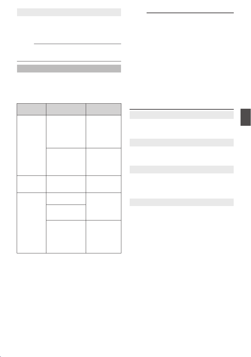
9
SD Aspect
For setting the aspect ratio of the SD recording
image when [System] is set to “HD+SD”, “SD”, or
“SD(SDI In)”.
[Setting Values: R16:9, 4:3]
Memo :
0
When [System] is set to “HD”, “HD+Web”, or
“HD(SDI In)”, this item is fixed at “16:9”.
Rec Mode
0
For selecting the record mode for recording to
the SD card.
(A P89 [Special Recording] )
0
The selectable options vary according to the
[Record Format] menu settings.
Format
No. of Frames for
Frame & Bit Rate
Setting values
MP4
(MPEG2)
QuickTime
(MPEG2)
MXF
(MPEG2)
30p, 25p, 24p Normal, Pre
Rec, Clip
Continuous,
Interval Rec,
Frame Rec,
Variable Frame
60p, 60i, 50p, 50i Normal, Pre
Rec, Clip
Continuous,
Interval Rec,
Frame Rec
AVCHD 50i, 60i Normal, Pre
Rec, Interval
Rec, Frame Rec
QuickTime
(H.264)
60i (U model)
50i (E model)
Normal, Pre
Rec, Clip
Continuous,
Interval Rec,
Frame Rec
60p, 60i, 50p, 50i
30p, 25p, 24p Normal, Pre
Rec, Clip
Continuous,
Interval Rec,
Frame Rec,
Variable Frame
Memo :
0
When [Slot Mode] is set to “Backup”, this item is
fixed at “Normal”.
0
[Variable Frame Rate] is enabled when
[WResolution]/[YResolution] is set to
“1920x1080” or “1280x720”, and the number of
frames for [WFrame & Bit Rate]/[YFrame & Bit
Rate] is set to 30p, 25p, or 24p.
0
When [System] is set to “HD+SD”, “HD+Web”,
“HD(SDI In)”, or “SD(SDI In)”, this item is fixed
at “Normal”.
0
When [Network] in the System menu is set to
other than “Off”, and the KA-M790G (Multicore
Remote Adapter: optional) is connected to the
rear of the camera recorder and power is
supplied from the 26-pin camera cable,
“Variable Frame” is not selectable.
9
Pre Rec Time
For setting the pre-recording time when [Rec
Mode] is set to “Pre Rec”.
[Setting Values: R5sec, 10sec]
9
Rec Frames
For setting the number of frames to record when
[Rec Mode] is set to “Frame Rec” or “Interval Rec”.
[Setting Values: R1frame, 3frames, 6frames]
9
Rec Interval
For setting the recording time interval when [Rec
Mode] is set to “Interval Rec”.
[Setting Values: R1sec, 2sec, 5sec, 10sec, 30sec,
1min, 2min, 5min, 10min, 30min, 1hour]
9
Variable Frame Rate
For setting the frame rate during recording when
[Rec Mode] is set to “Variable Frame”.
The available options vary according to the settings
for [Record Format] B [WResolution]/
[YResolution] and [WFrame & Bit Rate]/[YFrame
& Bit Rate].
(A P93 [Variable Frame Rec] )
System Menu
135
Menu Display and Detailed Settings

Slot Mode
For setting the operation of the card slot.
0
Series:
Mode that activates the two slots sequentially.
0
Dual:
Mode that activates the two slots at the same
time.
(A P85 [Dual Rec] )
0
Backup:
Mode that enables recording to slot B without
using the [REC] button. This item is selectable
only when [Rec Mode] is set to “Normal”.
Start or stop the recording using the [Backup
Rec] menu, or by pressing the button among
[USER1] to [USER10] that is assigned with
“Backup Trig” together with the [RET] button on
the lens.
(A P87 [Backup Rec] )
Memo :
0
When this is set to “Series”, and recordable
media are inserted in both slots, pressing the
[REC] button starts recording only to the card in
the selected slot (active slot).
0
When “Series” is selected, and [Record
Format] B [WFormat] is set to “AVCHD”, the
clips are recorded over the slots seamlessly
without interruption in the video.
0
When this is set to “Dual”, and recordable media
are inserted in both slots, pressing the [REC]
button starts simultaneous recording to the
cards in both slots.
9
Backup Rec
For starting/stopping backup recording with [REC]/
[STBY].
This item is selectable only when [Slot Mode] is set
to “Backup”.
Memo :
0
When recording is stopped due to no remaining
space on the media, etc., this item is fixed at
“STOP” and cannot be selected.
4GB File Spanning(SDXC)
A recording file is automatically split when the size
exceeds 4 GB, but you can record clips larger than
4 GB by setting this option to “Off”. (Up to a
maximum of 64 GB or 4 hours)
0
On:
Splits a file when it exceeds 4 GB or 30 minutes.
0
Off:
Splits a file when it exceeds 64 GB or 4 hours.
[Setting Values: ROn, Off]
Memo :
0
This option is only valid if the SD card used for
recording is of the SDXC format.
0
During simultaneous recording, such as Dual
Rec and backup recording, this option is valid
only when the SD cards in both slots are of the
SDXC format.
0
This option is valid only when [Record Format]
B [WFormat]/[YFormat] is set to
“QuickTime(MPEG2)”, “MXF(MPEG2)”, or
“QuickTime(H.264)”.
(A P133 [ W Format ] )
(A P134 [ Y Format ] )
Recording in DCIM Folder
When “On” is selected, files are recorded to the
DCIM folder of the SD card during MOV recording.
[Setting Values: ROn, Off]
Memo :
0
When “Off” is selected, folders containing
recorded clips may not be detectable in the MAC
OS environment.
0
To import clips to a Blu-ray disc & HDD recorder
produced by our company, set this item to “Off”
before recording.
Time Stamp
For setting whether to display shooting date/time
information in the recorded video.
[Setting Values: On, ROff]
Memo :
0
The date/time display style can be changed in
[LCD/VF] B [Display Settings] B [Date Style]/
[Time Style].
(A P124 [ Date Style ] )
(A P124 [ Time Style ] )
136
System Menu
Menu Display and Detailed Settings

0
When the date/time is hidden while the menu
screen, status screen or other screen is
displayed, the date/time during this period will
not be recorded to the video. A confirmation
screen appears if you try to display the menu
screen or status screen during recording.
0
When [System] is set to “HD+Web” or “HD+SD”,
the shooting date/time information cannot be
recorded to the image to be recorded in slot B.
0
When [Record Format] B [System] is set to
“HD(SDI In)” or “SD(SDI In)”, [Time Stamp]
cannot be set to “On”.
Clip Set
9
Clip Name Prefix
For setting the first four characters of the name of
the clip file to be recorded to the SD card.
Enter any of the 38 characters including alphabets
(upper case), numbers (0 to 9), “_” (underscore),
and “-” (hyphen) using the software keyboard.
(A P105 [Text Input with Software Keyboard] )
[Setting Values: xxxG] (The default value of xxx is
the last three digits of the serial number.)
Memo :
0
When [Main Menu] B [System] B [Record Set]
B [Record Format] B [WFormat] is set to
“AVCHD”, this setting is not reflected in the file
name of the clip.
However, it is recorded as the display name of
the clip in the thumbnail display.
9
Reset Clip Number
For assigning a new number (Clip Number) by
resetting it (0001).
Select [Reset] and press the Set button (R) to reset
the number.
When [WFormat] is set to “AVCHD”, the clip
number is reset to “00000”.
When other clips exist on the SD card, the smallest
available number is used after reset.
0
Example:
If the [Clip Name Prefix] is “ABCD”, and
“ABCD0001” already exists on the SD card,
“ABCD0002” will be assigned.
Clear Planning Metadata
Erases the planning metadata downloaded from
the FTP server.
Network/Settings Item
For specifying network-related settings.
The display of the software keyboard for input
varies according to the item you are setting.
(A P105 [Text Input with Software Keyboard] )
Web
For setting the functions that make use of the web
browser.
9
Web Access
To access via a web browser, set to “On”.
[Setting Values: ROn, Off]
9
Camera Name
For setting the name displayed on the web
browser. Enter not more than 8 characters using
the software keyboard.
0
Default value:
HM890 A B
HM850 C D
9
Login Name (Fixed)
The login name is “prohd”. It cannot be changed.
9
Login Password
Changes the password for accessing via a web
browser.
The current password is displayed. Enter a new
password directly.
Enter not more than 31 characters using the
software keyboard.
Live Streaming Set
For specifying settings for distributing live video
images.
Memo :
0
Users cannot access this menu in the following
cases.
0
When [Record Format] B [System] is set to
“HD+SD” or “HD+Web”
0
When [Record Format] B [Frame & Bit
Rate] is set to “24p”
System Menu
137
Menu Display and Detailed Settings
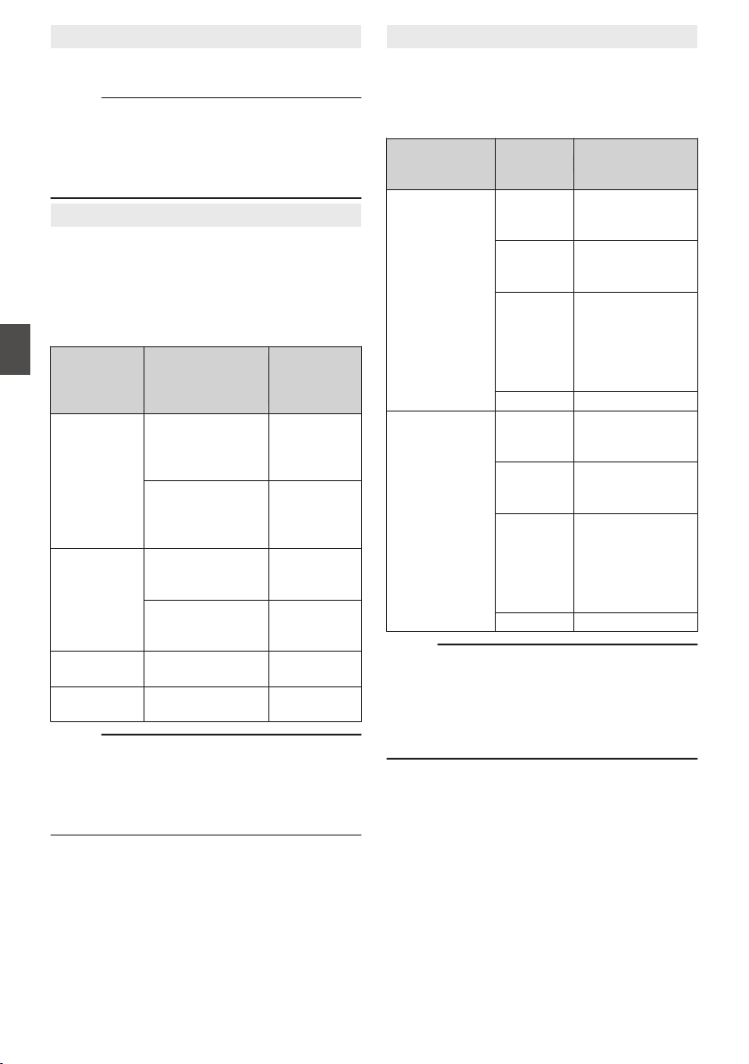
9
Live Streaming
Starts live distribution when “On” is selected.
[Setting Values: On, ROff]
Memo :
0
“On” cannot be selected if network connection
is not established.
0
“On” cannot be selected when FTP is running.
0
Live streaming switches to “Off” when the power
is turned off.
9
Resolution
For setting the resolution of the video image during
live distribution.
The camera recorder restarts when the setting is
changed.
The available options vary according to the settings
for [WResolution] and [WFrame & Bit Rate] under
[Record Format].
W Resolution
No. of Frames for
WFrame & Bit
Rate
Setting
values
(R: default
value)
1920x1080,
1440x1080
60p, 60i, 30p R1920x1080,
1280x720,
720x480,
480x270
50p, 50i, 25p R1920x1080,
1280x720,
720x576,
480x270
1280x720 60p, 30p R1280x720,
720x480,
480x270
50p, 25p R1280x720,
720x576,
480x270
720x480 (U
model)
60i 720x480,
480x270
720x576 (E
model)
50i 720x576,
480x270
Memo :
0
The settings cannot be changed during live
streaming or recording.
0
When [System] B [Record Set] B [Record
Format] B [SD Aspect] is set to “4:3”, the aspect
ratio of the live streaming image becomes “4:3”.
9
Frame & Bit Rate
For setting the frame rate and encoding bit rate of
the video image during live distribution.
The available options vary according to the settings
for [Resolution] above, as well as [WFrame & Bit
Rate] under [Record Format].
No. of Frames for
W
Frame & Bit
Rate
Resolution
Setting values
(R: default value)
60p, 60i, 30p 1920x1080 R60i (8.0 Mpbs),
60i (5.0 Mpbs),
60i (2.5 Mbps)
1280x720 R30p (5.0 Mpbs),
30p (3.0 Mpbs),
30p (1.5 Mbps)
720x480 60i (5.0 Mpbs),
R60i (3.0 Mpbs),
60i (1.5 Mbps),
60i (0.8 Mbps),
60i (0.3 Mbps),
60i (0.2 Mbps)
480x270 30p (0.2 Mbps)
50p, 50i, 25p 1920x1080 R50i (8.0 Mpbs),
50i (5.0 Mpbs),
50i (2.5 Mbps)
1280x720 R25p (5.0 Mpbs),
25p (3.0 Mpbs),
25p (1.5 Mbps)
720x576 50i (5.0 Mpbs),
R50i (3.0 Mpbs),
50i (1.5 Mbps),
50i (0.8 Mbps),
50i (0.3 Mbps),
50i (0.2 Mbps)
480x270 25p (0.2 Mbps)
Memo :
0
The settings cannot be changed during live
streaming.
0
An encoding bit rate exceeding 5.0 Mbps cannot
be selected when [Type] is set to “RTSP/RTP”.
0
An encoding bit rate exceeding 3.0 Mbps cannot
be selected when [Type] is set to “ZIXI”.
138
System Menu
Menu Display and Detailed Settings

9
Type
For setting the system to transfer videos for
distribution.
[Setting Values: RMPEG2-TS/UDP, MPEG2-TS/
TCP, RTSP/RTP, ZIXI]
Memo :
0
Use reception devices that are compatible with
the respective transfer systems.
0
To use the “ZIXI” setting, a dedicated server is
needed separately.
9
UDP/TCP Settings
For specifying the settings that are enabled only
when [Type] is set to “MPEG2-TS/UDP” or
“MPEG2-TS/TCP”.
Memo :
0
The settings cannot be changed during live
streaming.
o Destination Address
For setting details such as the host name and the
IP address of the live distribution destination.
* Enter not more than 127 characters using single-
byte alphanumeric characters (a to z, 0 to 9),
single-byte hyphen [-], or dot [.].
o Destination Port
Enter the network port number of the live
distribution destination using an integer between 1
and 65535.
The default value is 6504.
9
RTSP/RTP Settings
For specifying the settings that are enabled only
when [Type] is set to “RTSP/RTP”.
Memo :
0
The settings cannot be changed during live
streaming.
o Password
Changes the password for RTSP authentication to
enable client access. The current password is
displayed. Enter a new password directly.
There is no default value (blank).
* Enter not more than 31 characters.
9
ZIXI Settings
For specifying the settings that are enabled only
when [Type] is set to “ZIXI”.
Memo :
0
The settings cannot be changed during live
streaming.
o Destination Address
For setting details such as the host name and the
IP address of the live distribution destination.
* Enter not more than 127 characters using single-
byte alphanumeric characters (a to z, 0 to 9),
single-byte hyphen [-], or dot [.].
o Destination Port
Enter the network port number of the live
distribution destination using an integer between 1
and 65535.
The default value is 2088.
o Stream ID
For setting the registered stream ID of the live
distribution destination.
The default value varies with the product model.
* Enter not more than 63 characters.
o Password
For setting the [Stream ID] password.
There is no default value (blank).
* Enter not more than 127 characters.
o Latency
For setting the latency mode.
[Setting Values: Medium, RLow]
Connection Setup
For specifying the settings for connecting to the
network.
A [Wizard] screen will appear according to the
adapter connected to the rear [HOST] terminal.
Follow the instructions to perform the setting.
You can Store, Load, and Delete the settings
specified on the [Wizard] screen.
9
Wizard
A [Wizard] appears according to the adapter
connected to the rear [HOST] terminal.
Follow the instructions on the screen to perform
setting.
9
Load
Loads the settings on the [Wizard] screen.
(A P198 [Reading the Connection Settings
File] )
9
Store
Saves the settings on the [Wizard] screen.
(A P197 [Saving the Connection Settings File] )
9
Delete
Deletes the saved settings.
(A P199 [Deleting Connection Settings] )
System Menu
139
Menu Display and Detailed Settings

Metadata Server
For registering the FTP server for importing the
metadata and the path of the file to be imported.
Up to 4 settings can be registered.
9
Meta-FTP1 to Meta-FTP4
(The name that is specified in the
respective [Alias] items is displayed.)
o Alias
For setting a name to distinguish the settings of this
camera recorder.
The name set in this item will be displayed in the
[Import Metadata] options.
* Enter not more than 31 characters.
o Protocol
For setting the protocol of the FTP server to be
connected.
0
FTP:
Protocol that does not encrypt the incoming and
outgoing data.
0
SFTP:
Protocol that encrypts incoming and outgoing
data using SSH.
0
FTPS:
Protocol that encrypts incoming and outgoing
data using SSL or TLS. It uses an implicit mode
(starts encrypted communication once
connection starts).
0
FTPES:
Protocol that encrypts incoming and outgoing
data using SSL or TLS. It uses an explicit mode
(starts encrypted communication after
permission is granted).
[Setting Values: RFTP, SFTP, FTPS, FTPES]
o Server
For setting the server name (“mystation.com”, etc.)
or the IP address (“192.168.0.1”, etc.) of the FTP
server.
* Enter not more than 127 characters using single-
byte alphanumeric characters (a to z, 0 to 9),
single-byte hyphen [-], or dot [.].
o Port
Enter the FTP server port number to use using an
integer between 1 and 65535.
The default value varies with the Protocol setting.
(FTP: 21, SFTP: 22, FTPS: 990, FTPES: 21)
o File Path
Enter the path name for the metadata file (“/pub/
meta.xml”, “/home/user/meta2.xml”, etc.)
* Enter not more than 127 characters.
o Username
Enter the user name for connecting to the FTP
server.
* Enter not more than 31 characters.
o Password
Enter the password for connecting to the FTP
server.
* Enter not more than 31 characters.
o PASV Mode
For setting whether to set the communication mode
used for file transfer to the passive mode.
Set to “On” if the camera is inside a firewall, and a
connection from the FTP server to the camera
cannot be established.
[Setting Values: On, ROff]
Memo :
0
When [Protocol] is set to “SFTP”, this item
appears as “---” and cannot be selected.
Clip Server
For setting the server and directory for uploading
recorded clips in the SD card to the FTP server.
9
Clip-FTP1 to Clip-FTP4
(The name that is specified in the
respective [Alias] items is displayed.)
o Alias
For setting a name to distinguish the settings of this
camera recorder.
The name set in this item will appear on the [FTP
Upload] action screen of the thumbnail display.
* Enter not more than 31 characters.
o Protocol
For setting the protocol of the FTP server to be
connected.
0
FTP:
Protocol that does not encrypt the incoming and
outgoing data.
0
SFTP:
Protocol that encrypts incoming and outgoing
data using SSH.
0
FTPS:
Protocol that encrypts incoming and outgoing
data using SSL or TLS. It uses an implicit mode
(starts encrypted communication once
connection starts).
0
FTPES:
Protocol that encrypts incoming and outgoing
data using SSL or TLS. It uses an explicit mode
(starts encrypted communication after
permission is granted).
[Setting Values: RFTP, SFTP, FTPS, FTPES]
140
System Menu
Menu Display and Detailed Settings

o Server
For setting the server name (“mystation.com”, etc.)
or the IP address (“192.168.0.1”, etc.) of the FTP
server.
* Enter not more than 127 characters using single-
byte alphanumeric characters (a to z, 0 to 9),
single-byte hyphen [-], or dot [.].
o Port
Enter the FTP server port number to use using an
integer between 1 and 65535.
The default value varies with the Protocol setting.
(FTP: 21, SFTP: 22, FTPS: 990, FTPES: 21)
o Dir. Path
Enter the path name for the directory to upload to
(“/pub”, “/home/user”, etc.)
* Enter not more than 127 characters.
o Username
Enter the user name for connecting to the FTP
server.
* Enter not more than 31 characters.
o Password
Enter the password for connecting to the FTP
server.
* Enter not more than 31 characters.
o PASV Mode
For setting whether to set the communication mode
used for file transfer to the passive mode.
Set to “On” if the camera is inside a firewall, and a
connection from the FTP server to the camera
cannot be established.
[Setting Values: On, ROff]
Memo :
0
When [Protocol] is set to “SFTP”, this item
appears as “---” and cannot be selected.
Reset Network
Restores all items in the [Network] menu to their
default settings.
System Menu
141
Menu Display and Detailed Settings
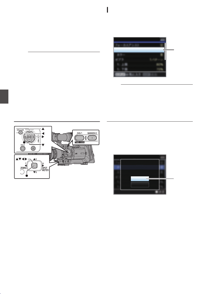
Adding/Editing
Frequently Used Menu
Items
You can select and add/edit frequently used menu
items freely to create a personal menu screen
(Favorites Menu).
Memo :
0
[Favorites Menu] is only enabled in the Camera
mode. [Favorites Menu] remains unchanged
even when the recording format changes.
0
When [Main Menu] B [System] B [Record Set]
B [Record Format] B [System] is set to “HD(SDI
In)” or “SD(SDI In)”, [Favorites Menu] is
disabled.
0
Up to 20 menu items can be added.
0
Added items in [Favorites Menu] will not be reset
even when [Main Menu] B [Reset All] is
executed.
0
Long descriptive names may be displayed for
the menu items in [Favorites Menu] to enable
better understanding.
.
Registration to Favorites Menu
1
Press the [MENU] button to open the [Main
Menu] screen.
2
Select the menu or submenu item to add.
.
2
Normal
Ty p e
Shooting Assist
Memo :
0
Adding items to [Favorites Menu] cannot be
performed in the following cases. [USER1 Add]
is displayed in gray in the operation guide.
0
Selected item is already added to [Favorites
Menu].
0
Number of menu items that can be added (20
items) is exceeded.
3
Press the [OIS/1] button.
A screen to confirm the addition appears.
4
Select [Add] and press the Set button (
R).
The selected menu item is added to [Favorites
Menu].
.
4
Ty p e
Cancel
Add
Focus Assist
Add to Favorites Menu?
142
Adding/Editing Frequently Used Menu Items
Menu Display and Detailed Settings
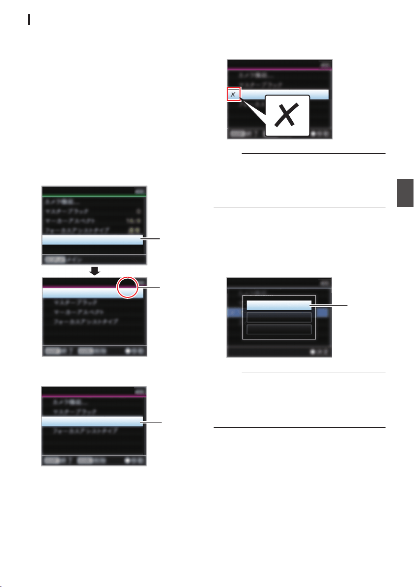
Editing Favorites Menu
You can delete or change the order of the items
added to [Favorites Menu].
Deleting Items from [Favorites Menu]
1
Open the [Favorites Menu] screen.
A
Press the [MENU] button to open the [Main
Menu] screen.
B
Press the [DISPLAY] button or press and
hold down the [MENU] button to open the
[Favorites Menu] screen.
2
Select [Edit Favorites] and press the Set
button (
R) or crossed-shaped button (I).
The header turns magenta and the editing
mode is activated.
.
2
Header
(Magenta)
Camera Function...
Edit Favorites
Edit Favorites
Favorites Menu
3
Select the menu or submenu item to delete.
.
3
Aspect Marker
Edit Favorites
4
Press the [MARKER/2] button.
A delete mark (b) appears at the beginning of
the menu item.
.
Aspect Marker
Edit Favorites
Memo :
0
When the [MARKER/2] button is pressed again
while the menu item with the delete mark (b) is
selected, the menu item will be excluded from
the items to be deleted and the delete mark (b)
disappears.
5
Press the [OIS/1] button.
The option menu to exit the [Favorites Menu]
editing mode appears.
6
Select [Save & Exit] and press the Set
button (
R).
.
6
Cancel
Exit without Saving
Save & Exit
Edit Favorites
Memo :
0
Deletion is not complete until the changes are
saved with [Save & Exit].
0
To exit the editing mode without deleting any
items, select [Exit without Saving].
0
To return to the editing mode, select [Cancel].
Adding/Editing Frequently Used Menu Items
143
Menu Display and Detailed Settings
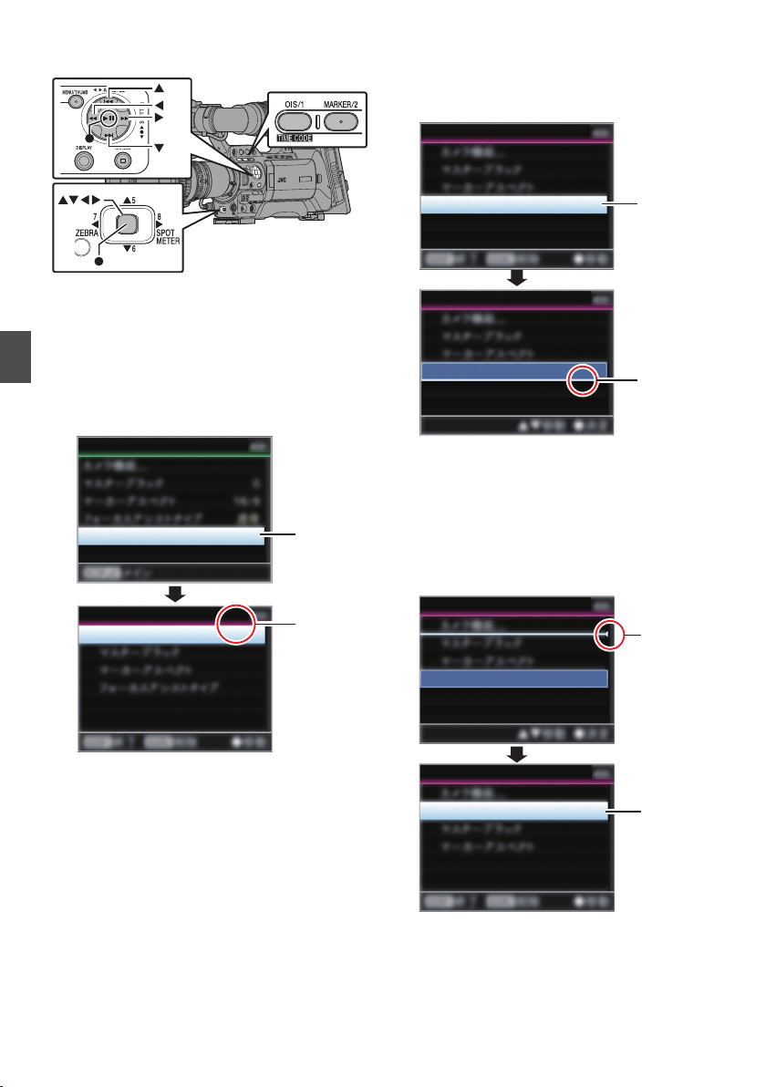
Changing the Order of Items in [Favorites
Menu]
.
1
Open the [Favorites Menu] screen.
Press the [MENU] button to open the [Favorites
Menu] screen.
2
Select [Edit Favorites] and press the Set
button (
R) or crossed-shaped button (I).
The header turns magenta and the editing
mode is activated.
.
2
Header
(Magenta)
Camera Function...
Edit Favorites
Edit Favorites
Favorites Menu
3
Select the menu or submenu item to move
and press the Set button (
R).
The moving mode is activated and a position
selection bar for the move appears.
.
3
Position
Selection
Bar
Ty p e
Ty p e
Focus Assist
Focus Assist
Edit Favorites
Edit Favorites
4
Select the position to move to with the
cross-shaped button (
JK).
Move the position selection bar with the cross-
shaped button (JK) and select a position to
move to.
5
Press the Set button (
R).
The selected item moves to the new position.
.
5
4
Ty p e
Ty p e
Focus Assist
Focus Assist
Edit Favorites
Edit Favorites
144
Adding/Editing Frequently Used Menu Items
Menu Display and Detailed Settings
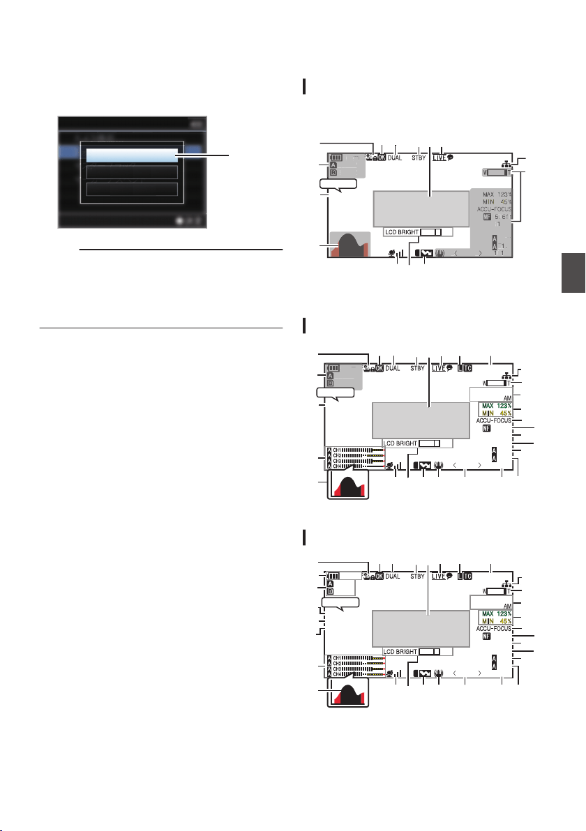
6
Press the [OIS/1] button.
The option menu to exit the [Favorites Menu]
editing mode appears.
7
Select [Save & Exit] and press the Set
button (
R).
.
7
Cancel
Exit without Saving
Save & Exit
Edit Favorites
Memo :
0
Moving is not complete until the changes are
saved with [Save & Exit].
0
To exit the editing mode without saving any
changes, select [Exit without Saving].
0
To return to the editing mode, select [Cancel].
Display Screen in Camera
Mode
Display 0 screen
This screen displays the event. It is also used to
display warnings only.
.
100min
50min
282min
12.5/ 30fps
P13000K
1/100
F1. 6
0
dB
AE+6
ND 1 / 64
de
+5
1
00
m
in
5
0mi
n
2
82
m
in
P
13000
K
1
/
1
00
F
1
.
6
0
d
B
AE
+
6
ND
1
/
64
SDI IN Z
※2
※1
A
D
c
J KI
X
b
a
※2
*1 Appears only during warnings
*2 Appears only during operation
Display 1 screen
.
100min
50min
282min
12.5/ 30fps
P13000K
1/100
F1. 6
0dB
AE+6
ND 1 / 64
12 :34 :56
Jan 24 ,2014
00:00:00.00
5 . 6 f t
+5
1
00
min
50
m
i
n
2
82
m
in
※
D
A
G
M
J
L N
O
Q
S
R
T
U
W
V
YZ
P
K
I
X
bc a
d
e
H
SDI IN Z
* Appears only during warnings
Display 2 screen
.
100min
50min
282min
12.5/ 30fps
P13000K
1/100
F1. 6
0
dB
AE+6
ND 1 / 64
12 :34 :56
Jan 24 ,2014
00:00:00.00
1920x1080
30p HQ
5 . 6 f t
+5
D
A
C
G
M
J
L N
O
Q
S
R
T
U
W
V
YZ
c
b
E
F
B
c
P
K
I
X
a
H
d
SDI IN Z
Adding/Editing Frequently Used Menu Items
145
Menu Display and Detailed Settings

A
Operation Lock Icon
Appears when the operation lock feature is
turned on.
(A P48 [About the Operation Lock Feature] )
B
Voltage/Battery Power
Displays the current status of the power supply
in use.
(A P32 [Power Status Display] )
Memo :
0
Displayed in the Display 0 and Display 1 screens
during warnings only.
C
Remaining Space on Media
Displays the remaining recording time of the SD
cards in slot A and slot B separately.
W
: Currently selected slot. (White card)
W z : Write-protect switch of SD card is set.
W!INVALID : SD card cannot be read or
written to, or restored.
W!FORMAT : SD card requires
formatting.
W!RESTORE : SD card requires
restoring.
W
!INCORRECT
:
0
When [Rec Mode] is set to other than
“AVCHD”/“SD”/“Web” with a Class 4 SD
card inserted.
0
When the SD card is not supported.
W!REC INH :
0
When attempting to record in 50p or 50i to
an SD card recorded in [AVCHD]60p or
60i (or vice versa).
0
When attempting to record a large clip
while a media that does not support large
clip recording is inserted.
(A P136 [ 4GB File Spanning(SDXC) ] )
0
When an SD card lower than Class 10 is
inserted while in the XHQ mode.
The following icons are displayed during FTP
upload.
(A P180 [Uploading a Recorded Video Clip] )
Icon Status
.
FTP transfer is in progress.
Three images are alternately
displayed, and the arrows
become animated. In this case,
instead of the recordable time of
the SD card, an estimated value
of the remaining transfer time is
displayed.
.
(Yellow)
Error has occurred during FTP
transfer.
Memo :
0
This item is not displayed when [Main Menu] B
[LCD/VF] B [Display Settings] B [Media
Remain] is set to “Off”. However, warnings will
be displayed.
(A P123 [ Media Remain ] )
0
Displayed on the Display 0 and Display 1
screens only in the case of warnings. (When the
remaining time is shorter than 3 minutes)
The icons appear on all display screens in the
following cases.
0
When recording is performed to only one of
the slots while [System] B [Record Set] B
[Slot Mode] is set to “Dual”.
(A P136 [ Slot Mode ] )
0
When recording is performed to only one of
the slots while [System] B [Record Set] B
[Record Format] B [System] is set to “HD
+SD” or “HD+Web”.
(A P132 [ System ] )
0
The displayed time is an estimate.
D
Frame rate C D
Frame rate/SDI IN A B
0
Displayed as xx/yy fps (xx: recording frame
rate, yy: playback frame rate) only when [Rec
Mode] is set to “Variable Frame”.
(A P135 [ Rec Mode ] )
0
“SDI IN Z” is displayed when a device is
connected to the [SDI IN] terminal, and
[System] B [Record Set] B [Record
Format] B [System] is set to “HD(SDI In)” or
“SD(SDI In)”.
(A P132 [ System ] )
146
Display Screen in Camera Mode
Display/Status Screen
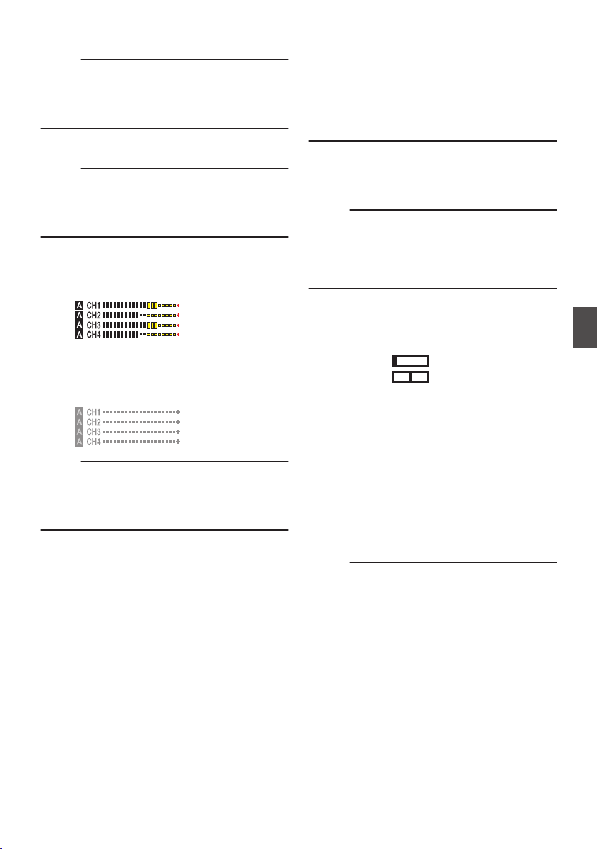
E
Resolution
Displays the video image resolution.
Memo :
0
This item is not displayed when [Main Menu] B
[LCD/VF] B [Display Settings] B [Record
Format] is set to “Off”.
(A P122 [ Record Format ] )
F
Frame Rate/Bit Rate
Displays the frame rate and bit rate in pairs.
Memo :
0
This item is not displayed when [Main Menu] B
[LCD/VF] B [Display Settings] B [Record
Format] is set to “Off”.
(A P122 [ Record Format ] )
G
Audio Level Meter
0
Displays the audio levels for CH-1 to CH-4.
0
a appears on the screen when in the Auto
mode.
.
0
When [Rec Mode] B [Rec Mode] is set to
“Frame Rec”, “Interval Rec”, or “Variable
Frame”, audio cannot be recorded and the
audio level meter is grayed out.
.
Memo :
0
This item is not displayed when [Main Menu] B
[LCD/VF] B [Display Settings] B [Audio Meter]
is set to “Off”.
(A P123 [ Audio Meter ] )
H
Histogram Display
This item is displayed when [Main Menu] B
[LCD/VF] B [Display Settings] B [Histogram] is
set to “On”.
(A P123 [ Histogram ] )
Memo :
0
When the histogram is displayed, the audio level
meter display is turned off temporarily.
I
GPS Mark
When [Main Menu] B [System] B [GPS] is set
to “On”, the signal reception status is displayed.
(A P130 [ GPS ] )
Memo :
0
The display changes according to the signal
reception sensitivity. If signals cannot be
received, the H mark appears in yellow.
0
This item is not displayed when [GPS] is set to
“Off”.
J
Volume Operation Indicator
This item is displayed when the LCD BRIGHT
and LCD PEAKING values (-10 to +10) are
changed.
.
LCD BRIGHT
LCD PEAKING
-10
0
K
Flash Band Correction Mark
This item is displayed when [Main Menu] B
[Camera Function] B [Flash Band Correction] is
set to “On”.
(A P108 [ Flash Band Correction ] )
L
Image Stabilizer Icon F
Displayed when the image stabilizer is ON.
i
: When [Level] of [OIS] is set to
“Normal”.
j
: When [Level] of [OIS] is set to
“High”.
Memo :
0
If image stabilizer is set to “OFF” when the
Display 0 screen is displayed, h appears for 3
seconds.
0
Displayed in the Display 0 screen only when
there is a change.
Display Screen in Camera Mode
147
Display/Status Screen

M
White Balance Mode
Displays the current white balance mode.
(*****K indicates color temperature)
A<*****K> : When the white balance is set to
Auto A.
B<*****K> : When the white balance is set to
Auto B.
P<*****K> : When the white balance is set to
Preset.
a
<FAW> : During Full Auto White Balance
mode.
Z
<FAW> : When [AE LOCK] is set to “On”
during Full Auto White Balance
mode.
Memo :
0
Displayed in the Display 0 screen only when
there is a change.
N
Shutter
0
The current shutter speed is displayed when
the shutter is set to “On”.
(A P108 [ Shutter ] )
0
a is displayed when the [FULL AUTO] switch
is set to “ON” to enable Full Auto shooting
mode, or when the [SHUTTER] button is
pressed to enable automatic shutter mode.
Memo :
0
The variable range of the shutter speed varies
according to the video format settings.
(A P60 [Setting the Electronic Shutter] )
0
Displayed in the Display 0 screen only when
there is a change.
0
If the shutter speed is not displayed, the shutter
is OFF.
O
Iris F-Number
Displays F-number of the lens iris.
P
Gain
0
Displays the gain value.
0
a is displayed in the ALC mode during
Manual shooting.
0
Z
is displayed when AE LOCK is set to “ON”.
0
“LUX30” or “LUX36” is displayed when in the
low-light shooting mode.
Memo :
0
Displayed in the Display 0 screen only when
there is a change.
Q
AE Level
0
Appears when the AE function is activated,
and [Main Menu] B [Camera Function] B
[AE Level] is set to a value other than
“Normal”.
(A P109 [ AE Level ] )
0
When operated while manual operation is
disabled, “AE” blinks for about 5 seconds.
0
When face detection is enabled and [Face
Detect] is set to “AF&AE”, q appears on the
left side of “AE”.
(A P56 [Adjusting the Focus by Face
Detection F] )
R
ND Filter Position
Displays the current ND filter position.
Memo :
0
This item is not displayed when [Main Menu] B
[LCD/VF] B [Display Settings] B [ND Filter] is
set to “Off”.
(A P122 [ ND Filter ] )
0
Displayed in the Display 0 screen only when
there is a change.
S
Focus Display F
0
Displays the value of the focal length during
manual focus.
0
e is displayed during Auto Focus.
0
When face detection is enabled, q appears
on the left side of e.
(A P56 [Adjusting the Focus by Face
Detection F] )
(A P112 [ Face Detect F ] )
0
If [Main Menu] B [Camera Function] B [AF
Assist] is set to “Area”, the
icon appears
on the left side of e.
(A P110 [ AF Assist F ] )
Memo :
0
You can specify whether to display the focus
value (“Feet”/“Meter”) or turn off the display in
[Main Menu] B [LCD/VF] B [Display Settings] B
[Focus].
This item will not be displayed when “Off” is
selected.
(A P122 [ Focus F ] )
0
Displayed in the Display 0 screen only when
there is a change.
148
Display Screen in Camera Mode
Display/Status Screen
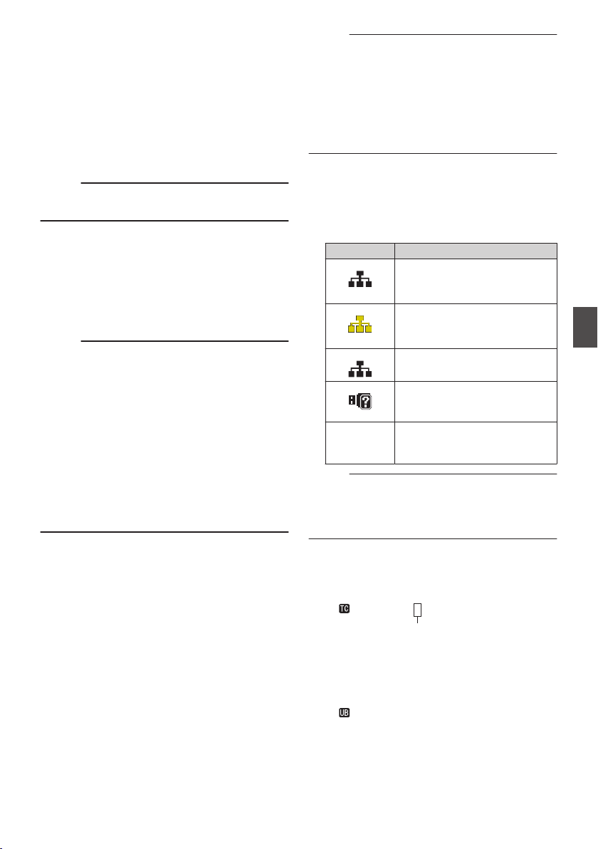
T
Focus Assist
0
“FOCUS” is displayed when auto focus is
activated.
0
When ACCU-Focus is enabled, “ACCU-
FOCUS” blinks for about 10 seconds while
Focus Assist starts up, after which the
“FOCUS” indicator lights up.
0
If recording starts while [ACCU-Focus] is
active, [ACCU-Focus] will be forcibly
deactivated.
(A P121 [ Focus Assist ] )
Memo :
0
Displayed in the Display 0 screen only when
there is a change.
U
Luminance Information
Displayed when the Spot Meter function is
activated.
(A P80 [Setting Spot Meter] )
MAX : Maximum luminance
MIN : Minimum luminance
V
Date/Time Display
Displays the current date and time.
Memo :
0
The date/time display style can be specified in
[Main Menu] B [LCD/VF] B [Display Settings] B
[Date Style]/[Time Style].
(A P124 [ Date Style ] )
(A P124 [ Time Style ] )
0
This item is not displayed when [Main Menu] B
[LCD/VF] B [Display Settings] B [Date/Time] is
set to “Off”.
(A P124 [ Date/Time ] )
0
When [Main Menu] B [System] B [Record Set]
B [Time Stamp] is set to “On”, this item is not
displayed.
(A P136 [ Time Stamp ] )
W
Zoom Display
0
Displays the zoom position. (Zoom bar or
value)
0
The zoom bar will only be displayed for 3
seconds after the zoom operation is
activated.
0
The value will always be displayed. (0 to 99)
Memo :
0
You can specify the display method (Number/
Bar) and whether to turn off the display in [LCD/
VF] B [Display Settings] B “Zoom”.
This item will not be displayed when “Off” is
selected.
(A P122 [ Zoom F ] )
0
Displayed in the Display 0 screen only when
there is a change.
X
Network Connection Icon
When [Main Menu] B [System] B [Network] is
set to “On(SDI Off)” or “On(HDMI Off)”, the
network connection status is displayed.
This icon is not displayed when “Off” is selected.
(A P131 [ Network ] )
Icon Status
.
(Blink)
Connection is not established
(starting up, preparing for
connection)
.
(Yellow)
Connection is not established
(preparing for connection)
.
Connection is established
.
When a USB adapter different
from the connection settings is
detected
(No display) When an incompatible USB
adapter is detected, or when
[Network] is set to “Off”
Memo :
0
When a cellular adapter that supports LTE
connection display is in use, “LTE” will appear to
the left of the above icon when LTE connection
is detected.
Y
Time Code (I)/User’s Bit (J) Display
0
Displays the time code (hour: minute:
second: frame) or user’s bit data.
0
Example of time code display:
.
00:00:00:00
※
* Colon (:) denotes non-drop frames and dot (.)
denotes drop frames.
0
Example of user’s bit display:
.
FF EE DD 20
Display Screen in Camera Mode
149
Display/Status Screen
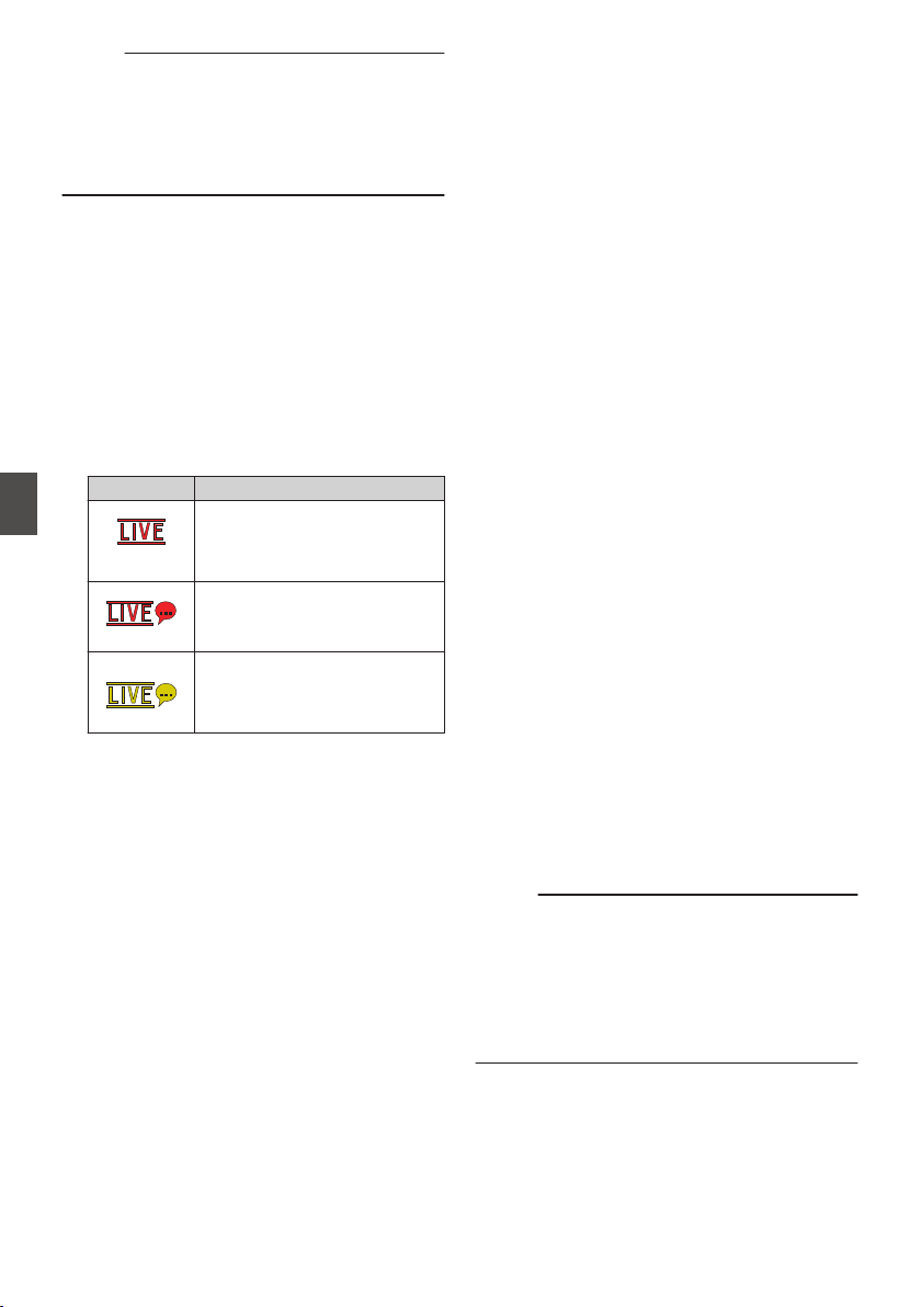
Memo :
0
You can specify whether to display the time
code, user’s bit, or turn off the display in
[LCD/VF] B [Display Settings] B [TC/UB].
This item will not be displayed when “Off” is
selected.
(A P123 [ TC/UB ] )
Z
Time Code Lock Indicator
When the built-in time code generator is
synchronized to the external time code data
input during the synchronization of time code
with another camera recorder, Z lights up.
(A P78 [Synchronizing the Time Code with an
External Time Code Generator] )
a
Live streaming mark
When [Main Menu] B [System] B [Network]/
[Settings] B [Live Streaming Set] B [Live
Streaming] is set to “On”, the distribution status
is displayed.
(A P138 [ Live Streaming ] )
Icon Status
.
(Red)
0
Distribution in progress
(good connection quality)
0
Blinks when distribution
starts or stops
.
(Red)
Distribution in progress (poor
connection quality)
.
(Yellow)
Waiting for connection (during
RTSP/RTP) or connection failed
b
Event/Warning Display Area
Displays error messages.
(A P202 [Error Messages and Actions] )
c
Media Status
---- : A card is not detected in the
selected slot, and [Tally
System] is also not set to
“Studio”
(A P130 [ Tally System ] )
STBY : Recording standby
RREC : Recording
REVIEW : Clip Review
(A P83 [Viewing Recorded Videos Immediately
(Clip Review)] )
STBY P : Pre Rec recording standby
(A P89 [Pre Rec] )
RRECP : Pre Rec recording
(A P89 [Pre Rec] )
STBY C : Clip Continuous Rec recording
standby
(A P89 [Clip Continuous Rec] )
RRECC : Clip Continuous Rec recording
(A P89 [Clip Continuous Rec] )
STBYC
(displayed in
yellow)
: Clip Continuous Rec recording
pause
(A P89 [Clip Continuous Rec] )
STBY N : Interval Rec recording standby
(A P92 [Interval Rec] )
STBYN
(displayed in
red)
: Interval recording pause
RRECN : Interval Rec recording
(A P92 [Interval Rec] )
STBY M : Frame Rec recording standby
(A P91 [Frame Rec] )
RRECM : Frame Rec recording
(A P91 [Frame Rec] )
STBYM
(displayed in
yellow)
: Frame Rec recording pause
(A P91 [Frame Rec] )
STOP : Unable to record to the card in
the slot
P.OFF : Power OFF
Q
: During clip cutter recording
(displayed for 3 seconds)
(A P85 [Splitting the Clips Freely (Clip Cutter
Trig)] )
CALL : Receiving call signals from an
external device, such as a
remote control unit
PGM : Receiving program signals
from an external device, such
as a remote control unit
PVW : Receiving preview signals
from an external device, such
as a remote control unit
d
Dual Rec/Backup Rec Display
“DUAL” is displayed in the Dual Rec mode and
“BACKUP” is displayed in the Backup Rec
mode.
(A P136 [ Slot Mode ] )
Memo :
0
This item is not displayed when [Slot Mode] is
set to “Series”.
0
This item is not displayed when [Main Menu] B
[LCD/VF] B [Display Settings] B [Media
Remain] is set to “Off”. However, warnings will
be displayed.
(A P123 [ Media Remain ] )
e
OK Mark
Displayed when OK mark has been appended.
(A P99 [Appending/Deleting OK Mark] )
150
Display Screen in Camera Mode
Display/Status Screen
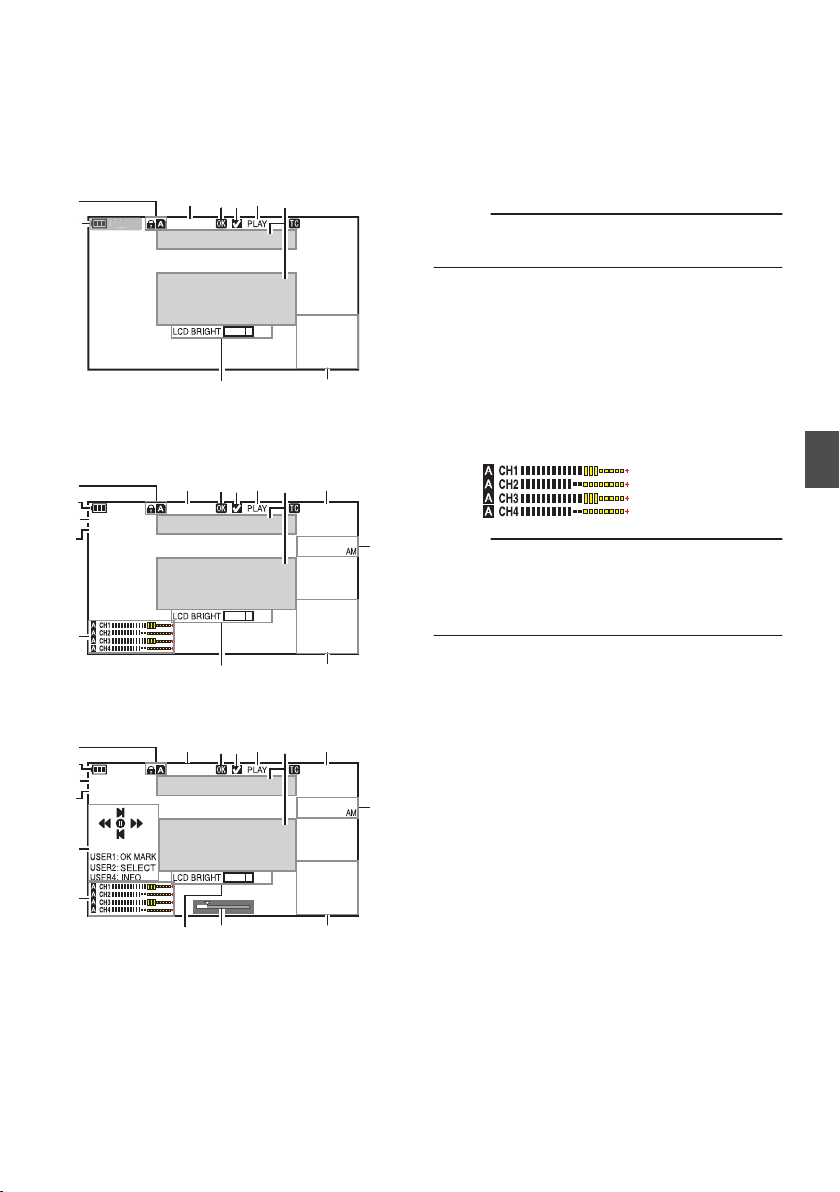
Display Screen in Media
Mode
Media Display 0 Screen
This screen displays the media status or event. It
is also used to display warnings only.
.
282min
+5
00:00:00.00
1000/ 2000
A
G
I
M
P
N
O
L
2
82
m
in
※
* Appears only during warnings
Media Display 1 Screen
.
282min
+5
12 :34 :56
Jan 24 ,2014
00:00:00.00
1920x1080
60 i HQ
1000/ 2000
A
F
G
I
J
KM
P
N
C
D
O
L
B
Media Display 2 Screen
.
282min
+5
12 :34 :56
Jan 24 ,2014
00:00:00.00
1920x1080
60 i HQ
1000/ 2000
B
A
F
G
I
J
KM
P
N
C
D
O
E
L
H
A
Media
0
Displays the media slot (A or B) of the
currently played clip.
0
z appears when the write-protect switch of
the SD card is set.
B
Voltage/Battery Power
Displays the current status of the power supply
in use.
(A P32 [Power Status Display] )
Memo :
0
Displayed in the Media Display 0 screen during
warnings only.
C
Resolution
Displays the video image resolution.
D
Frame Rate/Bit Rate
Displays the frame rate and bit rate in pairs.
E
Operation Guide
Displays a guide for the current operation
buttons.
F
Audio Level Meter
Displays the audio levels for [CH-1] to [CH-4].
.
Memo :
0
This item is not displayed when [Main Menu] B
[LCD/VF] B [Display Settings] B [Audio Meter]
is set to “Off”.
(A P123 [ Audio Meter ] )
G
Volume Operation Indicator
0
This item is displayed when the LCD
BRIGHT value (-10 to +10) is changed.
0
[LCD PEAKING +/-] operation is disabled in
the Media mode, and its value is fixed at “-10”.
(A P147 [Volume Operation Indicator] )
H
Position bar
Displays the current position in the video.
During trimming, the position bar appears in
green, and icons for the in and out points are
displayed.
(A P102 [Position bar] )
Display Screen in Media Mode
151
Display/Status Screen
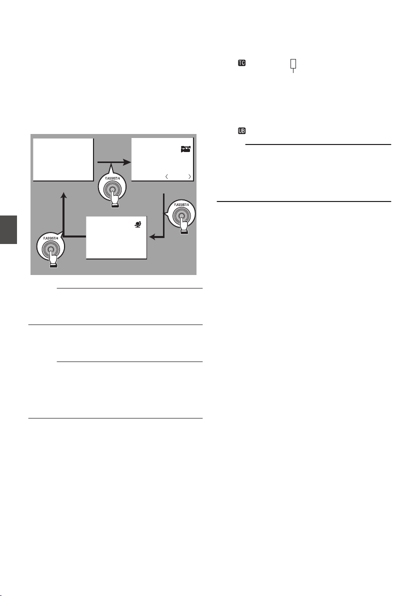
I
Information Display
Use the [F.ASSIST/4] button to switch between
camera information display, GPS display and
turning off the display.
0
The GPS display displays information on the
recording location of the video being played
back only when GPS information has been
recorded.
The local date/time is displayed.
0
Camera information display displays only
information of Gain, Iris, Shutter and White
Balance that have been recorded.
.
P13000K
1/100
F1. 6
0
dB
+35.483197
+139.652172
Oct 30,2014
07:01:58PM
GPS Display
Camera Information Display
Hide
Memo :
0
Trimming information is displayed while
trimming is in progress. In this case, pressing the
[F.ASSIST/4] button does not switch the display.
J
Date/Time Display
Displays the date/time that is recorded on the
currently played SD card.
Memo :
0
The date/time display style can be specified in
[LCD/VF] B [Display Settings] B [Date Style]/
[Time Style].
(A P124 [ Date Style ] )
(A P124 [ Time Style ] )
K
Time Code (I)/User’s Bit (J) Display
0
Displays the time code (hour: minute:
second: frame) or user’s bit data.
0
Example of time code display:
.
00:00:00:00
※
* Colon (:) denotes non-drop frames and dot (.)
denotes drop frames.
0
Example of user’s bit display:
.
FF EE DD 20
Memo :
0
You can specify whether to display the time
code, user’s bit, or turn off the display in [TC/UB]
of [Main Menu] B [LCD/VF] B [Display
Settings].
(A P123 [ TC/UB ] )
L
Event/Warning Display Area
Displays error messages.
(A P202 [Error Messages and Actions] )
M
Media Status
PLAY : Playing
STILL : Still picture playback mode
FWD * : High-speed playback in the
forward direction (* playback
speed: 5x, 15x, 60x, or 360x)
REV * : High-speed playback in the
reverse direction (* reverse
playback speed: 5x, 15x, 60x, or
360x)
STOP : Stop mode
P.OFF : Power OFF
N
Check Mark
Displayed when the currently played clip is
selected.
O
OK Mark
Displayed when OK mark has been appended.
(A P99 [Appending/Deleting OK Mark] )
P
Clip Information
Displays current clip number/total number of
clips.
152
Display Screen in Media Mode
Display/Status Screen
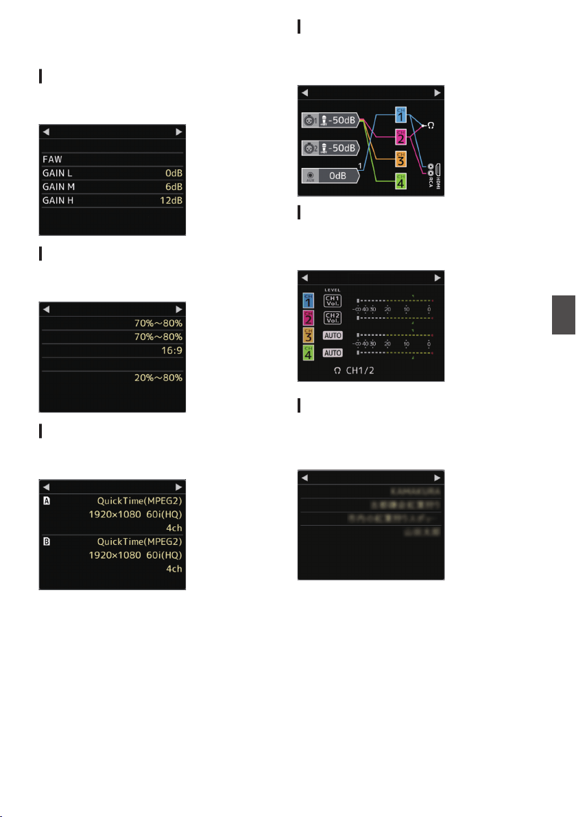
Status Screen
For checking the settings of the camera recorder.
Camera Screen
For checking information related to shooting using
the camera recorder.
.
AE Level
AE LEVEL SW
None
Standard
Shooting Mode
Camera
LCD/VF Screen
For checking information related to the LCD/VF
screen settings.
.
Histogram
Off
Safety Zone
Aspect Marker
Zebra 2
Zebra 1
LCD/VF
Record Format Screen
For checking information related to the recording
format settings.
.
Audio
Audio
Format
Format
Record Format
Audio Screen
For checking the settings related to audio input/
output.
(A P127 [Audio Set Item] )
.
Audio
Audio Level Screen
For checking audio related information such as
microphone volume level.
(A P69 [Audio Recording] )
.
Mix
Audio Level
Planning Metadata Screen
For checking the current planning metadata
setting.
(A P132 [ Record Format ] )
.
Creator
Description
Title2
Title1
Planning Metadata
Status Screen
153
Display/Status Screen
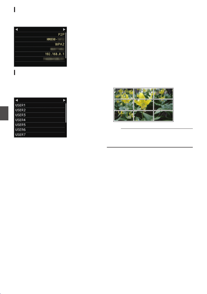
Network Screen
For checking the network-related settings.
(A P139 [ Wizard ] )
.
SSID
Live Streaming
MAC Address
IP Address
Passphrase
Security Type
Ty p e
Network
USER Switch Set Screen
For checking the status (functions assigned) of the
user buttons.
(A P42 [Assignment of Functions to User
Buttons] )
.
Zebra
None
None
Focus Assist
Load Picture File
Marker
OIS
USER Switch Set
Marker and Safety Zone
Displays
The Grid Marker, Marker, Safety Zone, and Center
Mark displays are useful in helping you determine
the angle of view for the video image according to
the shooting purpose.
The marker is displayed only in the Camera mode.
Displaying the Grid Marker
1
Set [LCD/VF]
B [Marker Settings] B [Grid
Marker] to “On”.
(A P121 [ Grid Marker ] )
A grid that divides the screen into 3x3 is
displayed.
.
Memo :
0
When [Grid Marker] is set to “On”, [Aspect
Ratio], [Aspect Marker], and [Safety Zone] do
not function.
154
Status Screen
Display/Status Screen
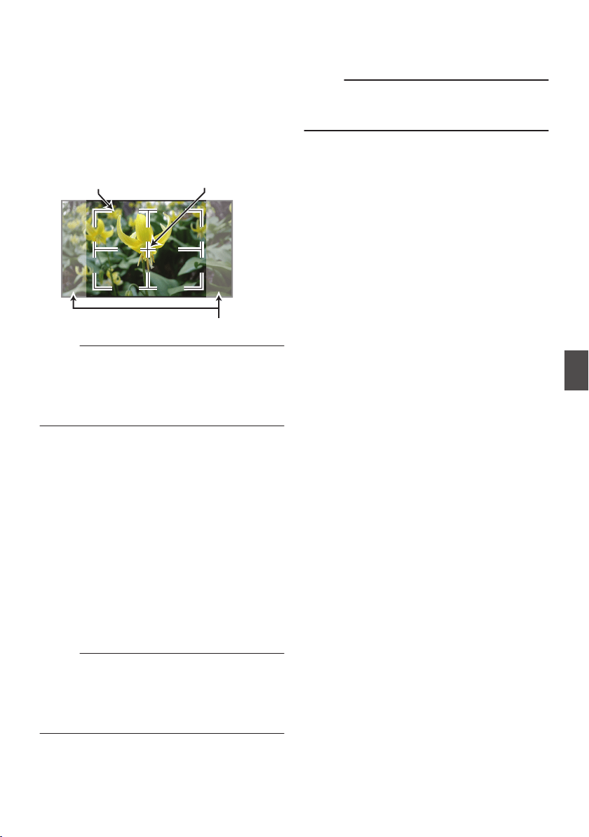
Displaying the Aspect Ratio, Aspect Marker,
Safety Zone, and Center Mark
1
Set [LCD/VF]
B [Marker Settings] B [Grid
Marker] to “Off”.
Perform setting for each of the [Aspect Ratio],
[Aspect Marker], [Safety Zone], and [Center
Mark] items.
0
Example of display when [Aspect Ratio] =
“4:3”, [Aspect Marker] = “Line+Halftone”, and
[Center Mark] = “On”
.
Aspect Marker
Center MarkSafety Zone
Memo :
0
You can turn On/Off the safety zone and center
mark displays using [LCD/VF] B [Marker
Settings] B [Aspect Ratio], [Safety Zone], and
[Center Mark].
(A P122 [ Safety Zone ] )
Smoothening the Skin
Color (Skin Detail
Function)
The Skin Detail function can be used to reduce the
contour enhancement of video signals for only the
skin areas so as to produce a smoother skin tone.
1
Set [Skin Detail] to “On”.
(A P117 [ Skin Detail ] )
Set [Main Menu] B [Camera Process] B
[Detail]/[Adjust] B [Skin Detail] to “On”.
Memo :
0
You can specify the adjustment level for the
contour enhancement of the skin tone in [Main
Menu] B [Camera Process] B [Detail]/[Adjust]
B [Skin Detail]/[Level].
(A P117 [ Level ] )
Color Bar Output
Color bars can be output on this camera recorder.
Memo :
0
The audio test signals (1 kHz) can be output
simultaneously with the color bar output.
(A P129 [ Test Tone ] )
To Output the Color Bar Using the Menu
To output color bars, follow the setting procedure
below.
1
Set [Camera Function]
B [Bars] to “On”.
(A P108 [ Bars ] )
Color bars are output.
To Output the Color Bar Using the User Button
1
Assign the “Bars” function to any of the
user buttons.
(A P42 [Assignment of Functions to User
Buttons] )
2
Press the user button that is assigned with
“Bars”.
Color bars are output.
Marker and Safety Zone Displays
155
Camera Features
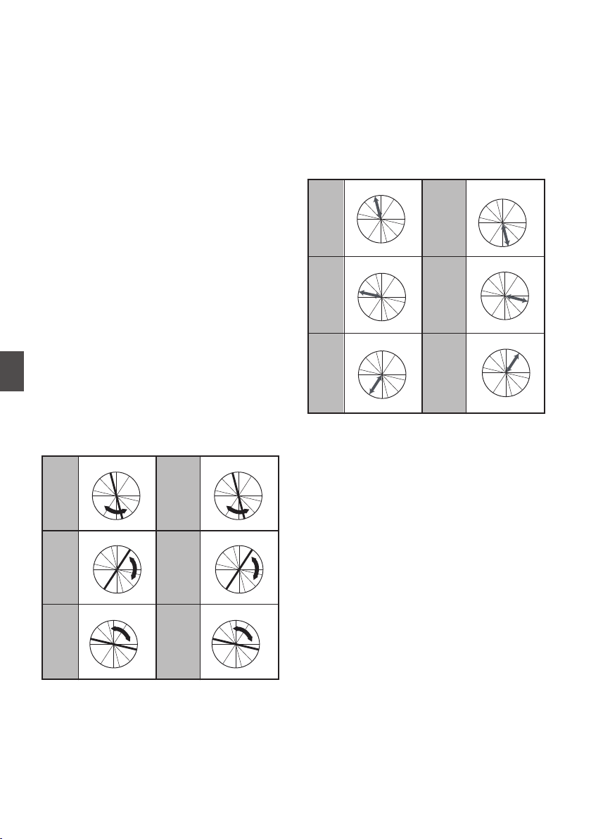
Adjusting Color Matrix
0
The color matrix of the camera recorder can be
adjusted to a color of the user’s preference.
0
When shooting is performed using multiple
cameras, the colors of the different cameras can
be adjusted, and a color of the user’s preference
can be set on this camera recorder.
0
The Saturation, Hue and Lightness of the
primary and complementary colors (6 colors in
total) can be set individually.
0
Adjust the color on the vector scope and
waveform monitor using the DSC color chart.
* The adjusted values of “Standard”, “Cinema
Vivid”, and “Cinema Subdued” in [Color Matrix]
can be stored individually.
(A P116 [ Color Matrix ] )
1
Select [Camera Process]
B [Color Matrix]/
[Adjust].
(A P116 [ Adjust ] )
2
Adjust Hue.
0
Select the color using the cross-shaped
button (JK) and confirm using the cross-
shaped button (I). (The cursor moves to
Hue.)
0
Pressing the cross-shaped button (J)
rotates the hue in the clockwise direction on
the vector scope.
0
Pressing the cross-shaped button (K)
rotates the hue in the anti-clockwise
direction on the vector scope.
.
R
Cy
B
G
Y
I
Mg
R
Cy
B
G
Y
I
Mg
R
Cy
B
G
Y
I
Mg
R
Cy
B
G
Y
I
Mg
R
Cy
B
G
Y
I
Mg
R
Cy
B
G
Y
I
Mg
MagentaGreen
BlueYellow
CyanRed
3
Adjust Saturation.
0
Press the cross-shaped button (I) to move
the cursor to Saturation.
0
Each of the colors changes in the direction
indicated by the arrow on the vector scope.
0
Pressing the cross-shaped button (J)
moves the color outward from the center of
the circle on the vector scope.
0
Pressing the cross-shaped button (K)
moves the color toward to the center of the
circle on the vector scope.
.
R
Cy
B
G
Y
I
Mg
R
C
y
B
G
Y
I
Mg
R
Cy
B
G
Y
I
Mg
R
Cy
B
G
Y
I
Mg
R
Cy
B
G
Y
I
Mg
R
Cy
B
G
YI
I
Mg
Magenta
Green
BlueYellow
CyanRed
4
Adjust Lightness.
0
Pressing the cross-shaped button (J)
lightens; and pressing the cross-shaped
button (K) darkens.
0
Press the cross-shaped button (I) to return
the cursor to Hue.
156
Adjusting Color Matrix
Camera Features
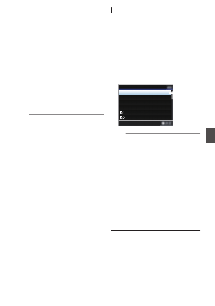
Configuring Setup Files
The menu settings can be stored on the camera
recorder or an SD card by saving them as a setup
file.
Loading a saved setup file enables you to
reproduce the appropriate setup state speedily.
The following types of setup files are available.
o Picture file:
File that contains image creation settings in
accordance to the shooting conditions ([Camera
Process] menu items).
o All File:
File that contains all menu settings, ranging from
video format settings to image creation settings
such as device settings and shooting conditions,
as well as the contents of the [Favorites Menu].
o [User File]:
File that contains settings from All File that are not
included in the [Camera Process] menu items.
(A P114 [Camera Process Menu] )
Memo :
0
Make use of the [Setup File] menu to save or
load a setup file.
0
The following operations can be performed on
the [Setup File] menu.
0
[Saving Setup Files] P 157
0
[Loading a Setup File] P 158
0
[Deleting Setup Files] P 159
Number of Storable Setup Files
Camera recorder : [CAM1] to [CAM4]
SD slot A : [ W 1 ] to [ W 8 ]
SD slot B : [ Y 1 ] to [ Y 8 ]
Compatibility
o User File/All File
0
Only User File/All File of the GY-HM890 and GY-
HM850 series can be loaded.
0
When User File/All File saved using GY-HM890
are loaded using GY-HM850, the functions that
only exist on GY-HM890 are ignored.
o Picture file
Only picture files of the GY-HM890 and GY-HM850
series can be loaded.
Saving Setup Files
1
Display the [Setup File] menu.
Select [Main Menu] B [System] B [Setup File]
and press the Set button (R).
(A P130 [ Setup File ] )
2
Select [Store File] and press the Set button
(
R).
3
Select [Picture File], [User File] or [All File],
and press the Set button (
R).
The existing files are displayed.
4
Select the file to be newly saved (or
overwritten) using the cross-shaped
button (
JK), and press the Set button (R).
.
4
<no file>
<no file>
<no file>
<no file>
<no file>
<no file>
CAM4
CAM3
CAM2
CAM1
Store Picture File
Memo :
0
Files cannot be written in the following cases.
(Displayed in gray, selection disabled)
0
When the inserted SD card is not supported or
not formatted. (File name appears as “---”.)
0
When a write-protected SD card is inserted
(a z mark appears beside the SD card icon).
5
Name the file.
0
Enter the subname using the software
keyboard.
(A P105 [Text Input with Software Keyboard] )
0
You can enter up to 8 characters for the
[Store File]/[Picture File] subname.
Memo :
0
When overwriting an existing file, the subname
of the existing file is displayed.
0
Select [Cancel] and press the Set button (R), or
press the [CANCEL] button to return to the
previous screen.
Configuring Setup Files
157
Camera Features
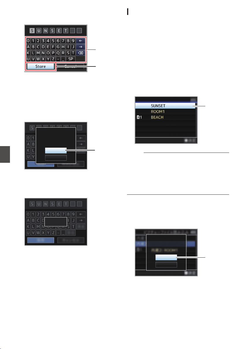
6
Select [Store] and press the Set button (
R).
.
6
5
7
Save the file.
0
A confirmation screen appears when you
choose to overwrite.
Select [Overwrite] on the confirmation
screen, and press the Set button (R). Saving
starts, and “Storing...” appears on the
screen.
.
:SUNSET
7
Load Picture File
Cancel
Overwrite
CAM1
Overwrite Picture File?
0
Saving starts, and “Storing...” appears on the
screen when the file is newly saved.
.
Storing...
8
Saving is complete.
After saving of the file is complete, “Complete”
appears on the screen, and the menu screen
closes automatically.
Loading a Setup File
1
Display the [Setup File] menu.
Select [Main Menu] B [System] B [Setup File]
and press the Set button (R).
(A P130 [ Setup File ] )
2
Select [Load File] and press the Set button
(
R).
3
Select [Picture File], [User File] or [All File],
and press the Set button (
R).
The existing files are displayed.
4
Select the file to load using the cross-
shaped button (
JK), and press the Set
button (
R).
.
4
CAM2
CAM1
Load Picture File
Memo :
0
When the write-protect switch of the inserted SD
card is set, a z mark appears beside the SD
card icon. Setup files can be loaded from an SD
card even if the write-protect switch is set.
0
Setup files that are completely incompatible will
not be displayed.
(A P157 [Configuring Setup Files] )
5
Select [Load] on the confirmation screen,
and press the Set button (
R).
Loading starts, and “Loading...” appears on the
screen.
.
:ROOM1
5
Cancel
Load
CAM2
Load Picture File?
158
Configuring Setup Files
Camera Features
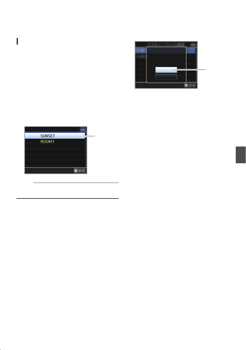
6
Reading is complete.
After reading of the file is complete, “Complete”
appears on the screen, and the menu screen
closes automatically.
Deleting Setup Files
1
Display the [Setup File] menu.
Select [Main Menu] B [System] B [Setup File]
and press the Set button (R).
(A P130 [ Setup File ] )
2
Select [Delete File] and press the Set button
(
R).
3
Select [Picture File], [User File] or [All File],
and press the Set button (
R).
The existing files are displayed.
4
Select the file to delete using the cross-
shaped button (
JK), and press the Set
button (
R).
.
4
CAM2
CAM1
Delete Picture File
Memo :
0
Scene files saved on the SD card cannot be
deleted.
5
Select [Delete] on the confirmation screen,
and press the Set button (
R).
Deletion starts, and “Deleting...” appears on the
screen.
.
:SUNSET
5
Cancel
Delete
CAM1
Delete Picture File?
6
Deletion is complete.
After file deletion is complete, “Complete”
appears on the screen.
Configuring Setup Files
159
Camera Features
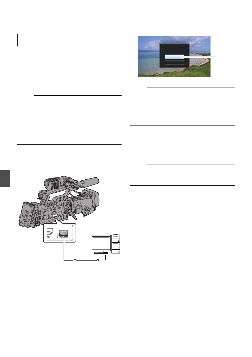
Managing/Editing Clips on
a PC
Loading Clips to the PC (USB
Connection Mode)
0
You can load clips to a PC by connecting the
camera recorder to the PC via the USB port.
Doing so enables clips stored in the SD card to
be managed and edited on the PC.
0
Files on the SD card can be managed/edited on
the connected PC in this mode only for USB
mass storage class devices that are recognized
by the said PC as a peripheral drive.
Memo :
0
Files cannot be written to the SD card.
0
Make sure to manage/edit files recorded in the
MP4 file format using the (JVC ProHD Clip
Manager) PC application software in the
supplied disc.
0
For details on how to install the application
software, refer to the [User's Guide] of the [JVC
ProHD Clip Manager] inside the supplied disc.
1
Connect the camera recorder to the PC
using a USB cable.
A confirmation message “Change to USB
Mode?” to enable the USB connection appears.
.
PC
2
Select [Change] using the cross-shaped
button (
JK), and press the Set button (R).
The camera recorder switches to USB mode.
.
2
Cancel
Change
Change to USB Mode?
Memo :
0
If recording is in progress, the “Change to USB
Mode?” message appears after recording
stops.
0
If playback is in progress, the camera recorder
switches to USB mode after the file closes
automatically, such as when playback stops.
Disconnecting
0
Disable the connection on the PC, then remove
the USB cable from the camera recorder.
0
Doing so exits the USB mode and switches the
camera recorder to Camera mode.
Memo :
0
The procedure for disabling the USB connection
varies according to the PC in use. For details,
refer to the instruction manual of the PC.
160
Managing/Editing Clips on a PC
Connecting External Devices

When your PC cannot recognize the SD
card
Confirm and update the OS of your PC.
OS Description
Windows XP/
Windows XP SP1
Necessary to update to SP2
or higher.
Windows XP SP2/
Windows XP SP3
Necessary to download the
update software.
(KB955704)
http://www.microsoft.com/
downloads/details.aspx?
familyid=1CBE3906-
DDD1-4CA2-B727-
C2DFF5E30F61&
displaylang=en
Windows Vista Necessary to update to SP1
or higher.
Windows Vista SP1/
Windows Vista SP2
Necessary to download the
update software.
(KB975823)
0
32 bit version
http://
www.microsoft.com/
downloads/en/
details.aspx?
FamilyID=2d1abe01-
0942-4f8aabb2-
2ad529de00a1
0
64 bit version
http://
www.microsoft.com/
downloads/en/
details.aspx?
FamilyID=7d54c53f-017c
-4ea5-
ae08-34c3452ba315
Windows 7 Necessary to download the
update software.
(KB976422)
0
32 bit version
http://
www.microsoft.com/
downloads/en/
details.aspx?
FamilyID=3ee91fc2-
a9bc-4ee1-
aca3-2a9aff5915ea
0
64 bit version
http://
www.microsoft.com/
downloads/en/
details.aspx?
FamilyID=73f766dd-
7127-4445-
b860-47084587155f
Windows 8.1 Please check the website of
Microsoft Corporation.
Connecting External
Monitor
0
To output live or playback video images and
audio sound to an external monitor, select the
output signals from the camera recorder, and
connect using an appropriate cable according to
the monitor to be used.
0
Choose the most suitable terminal according to
the monitor in use.
0
[HD/SD SDI OUT] terminal:
Outputs either the HD-SDI signal or SD-SDI
signal.
0
[VIDEO OUT] terminal:
Outputs composite video signals.
0
[HDMI] terminal:
Outputs HDMI signals.
Configure the settings in the [A/V Set] menu to
match the monitor to be connected.
(A P125 [ HDMI/SDI Out ] )
Memo :
0
When [Network] is set to “On(HDMI Off)” or
“On(SDI Off)”, either HDMI signal or SDI signal
is output.
(A P131 [ Network ] )
Managing/Editing Clips on a PC
161
Connecting External Devices
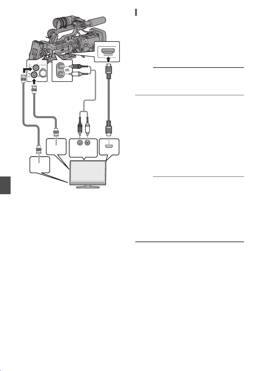
.
SDI IN
Audio input
VIDEO
IN
HDMI
* Select the output signal in [A/V Set] B [HDMI/SDI
Out].
(A P125 [ HDMI/SDI Out ] )
*
When [Record Format]
B
[System] is set to “SD”,
only SD-SDI signals are output.
(A P132 [ System ] )
* To display the menu screen or display screen on
the external monitor, set [A/V Set] B [Video Set]
B [HDMI Out Character]/[SDI Out Character]/
[VIDEO Out Character] to “On”.
(A P126 [ HDMI Out Character ] )
(A P126 [ SDI Out Character ] )
(A P126 [ VIDEO Out Character ] )
Connecting via SDI
0
Digital video signals, together with embedded
(superimposed) audio signals and time code
signals, are output for both the HD SDI and SD
SDI signals.
0
User’s bit output from the [HD/SD SDI] output
terminal is used as a flag to determine valid
video signals. Therefore, accurate values will
not be output.
Memo :
0
The sampling frequency for embedded
(superimposed) audio signals is 48 kHz. Time
code of the built-in time generator as well as
playback time code are also output.
Settings for SDI/Composite Down-Converted
Output
0
You can select the method to “down convert” HD
video images to SD images during SD SDI or
composite output.
0
Set using [A/V Set] B [Video Set] B [SD
Aspect].
0
The available modes include “Side Cut”, “Letter”
(blackened at the top and bottom), and
“Squeeze” (full size, compressed at the left and
right).
(A P125 [ SD Aspect ] )
Memo :
0
When [Record Format]
B
[System] is set to “SD”,
and [SD Aspect] is set to “4:3”, this item cannot be
selected.
(A P132 [ System ] )
0
When [Record Format] B [System] is set to
“SD”, and [SD Aspect] is set to “16:9”, “Side
Cut” in [A/V Set] B [Video Set] B [SD Aspect]
cannot be selected.
(A P125 [ SD Aspect ] )
(A P132 [ System ] )
162
Connecting External Monitor
Connecting External Devices
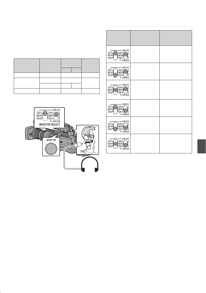
Connecting a Earphone
0
Audio output from the [PHONES] terminal can
be selected using the [A/V Set] B [Monitor] item
or the [MONITOR] selection switch on the
camera recorder.
(A P129 [ Monitor ] )
0
The different combinations of settings that are
output from the [PHONES] terminal and monitor
speaker are as follows.
[MONITOR]
Switch
Settings
[Monitor]
Settings
[PHONES]
Terminal
Speaker *
L R
[CH-1] - CH-1 CH-1
[BOTH] [Mix] CH-1+CH-2 CH-1+CH-
2
[Stereo] CH-1 CH-2
[CH-2] - CH-2 CH-2
* Audio is output from the speaker only in Media
mode. Does not output in the Camera mode.
.
1
Connect a earphone.
2
Select the channels to monitor using the
different combinations of the left and right
[MONITOR SELECT] switches.
[MONITOR
SELECT
]
Setting
Channels to
Monitor
Description
.
[CH-1] Outputs the audio
recorded in
[CH-1].
.
[CH-2] Outputs the audio
recorded in
[CH-2].
.
[CH-1]/[CH-2] Outputs the audio
recorded in
[CH-1] and
[CH-2].
.
[CH-3] Outputs the audio
recorded in
[CH-3].
.
[CH-4] Outputs the audio
recorded in
[CH-4].
.
[CH-3]/[CH-4] Outputs the audio
recorded in
[CH-3] and
[CH-4].
3
Use the [MONITOR] adjustment knob to
adjust the monitor volume.
Connecting a Earphone
163
Connecting External Devices
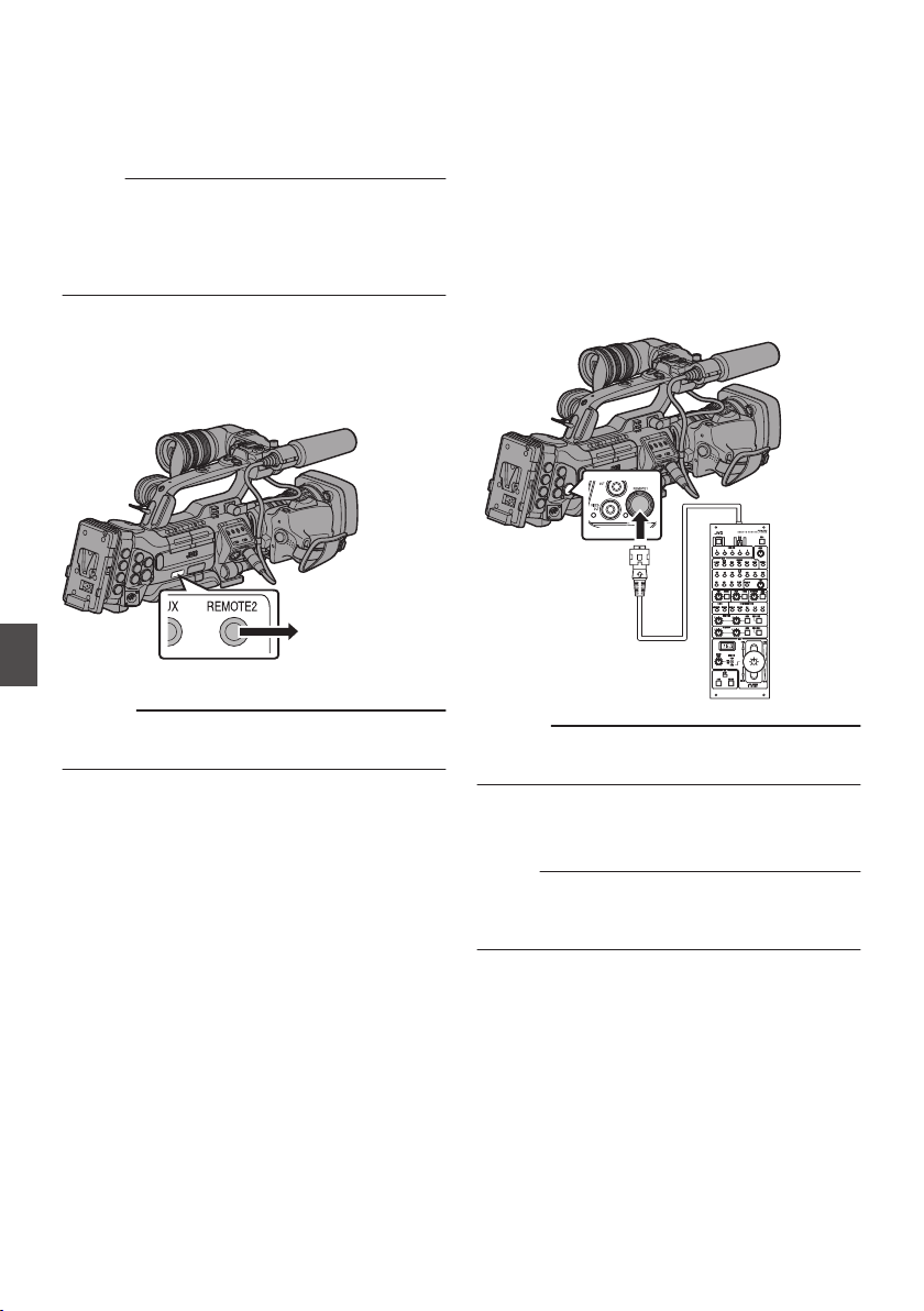
Connecting Wired Remote
Control
You can operate the functions of this unit with a
wired remote control.
Memo :
0
When the switches of the camera recorder and
remote control unit are operated at the same
time, the switch operation of the remote control
unit takes priority over that of the camera
recorder.
1
Connect a wired remote control to the
camera recorder.
Connect the wired remote control (sold
separately) to the [REMOTE2] terminal of this
camera recorder.
.
Connect the wired
remote control
Caution :
0
Turn off the power of the camera recorder when
connecting a wired remote control.
2
Turn on the power of the camera recorder.
Connecting a Remote
Control Unit
The switch functions of the camera recorder can be
configured using the remote control unit.
* Remote control units supported: RM-LP25U, RM-
LP55U, RM-LP20G
1
Connect the remote control unit to the
camera recorder.
Connect the remote cable of the remote control
unit to the [REMOTE1] terminal located at the
terminal section of this camera recorder.
.
RM-LP25U
Caution :
0
Turn off the power of the camera recorder when
connecting a remote control unit.
2
Turn on the power of the camera recorder.
3
Set the operate switch of the remote control
unit to ON.
Memo :
0
For details on the functions operable from the
remote control unit, please refer to [Functions
Operable from the Remote Control Unit] P 166.
164
Connecting Wired Remote Control
Connecting External Devices

Precautions on Using the Remote Control Unit
0
When the switches of the camera recorder and
remote control unit are operated at the same
time, the switch operation of the remote control
unit takes priority over that of the camera
recorder.
0
Focus and zoom operations cannot be
performed using the remote control unit.
0
The shutter speed may vary slightly from the
value displayed on the camera recorder.
0
When the frame rate of the [WFrame & Bit Rate]/
[YFrame & Bit Rate] items on the camera
recorder is set to “24p”, shutter speed cannot be
set to “1/60” from the remote control unit. The
shutter speed of “1/48” will be used even when
“1/60” is selected.
(A P133 [ W Frame & Bit Rate ] )
(A P134 [ Y Frame & Bit Rate ] )
0
While the camera recorder is in the Media mode,
the Auto White Balance feature does not
function even if you operate it from the remote
control unit.
0
When the H phase is set using a remote control
unit, only the H phase of the SD signal is
activated.
0
When setting the H Phase using a remote
control unit, any value beyond the setting range
in the menu of the camera recorder cannot be
set.
(A P126 [ HD-SDI H Phase ] )
Connecting a Remote Control Unit
165
Connecting External Devices
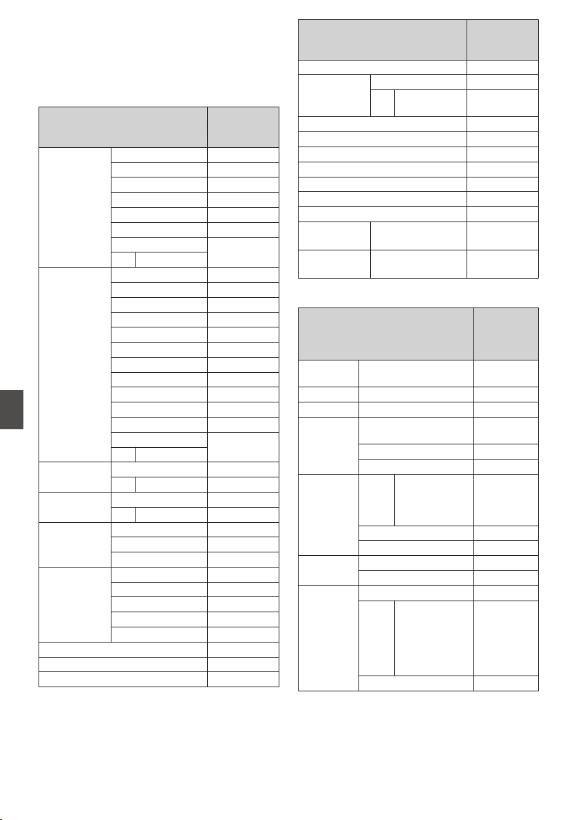
Functions Operable from
the Remote Control Unit
RM-LP25U
Function
P: Available
-: Not
available
SHUTTER NORMAL
P
1/100*1, 1/120*2
P
1/250
P
1/500
P
1/1000
P
1/2000
P
VARIABLE
P
- SPEED
GAIN -6dB
P
-3dB
P
0dB
P
3dB
P
6dB
P
9dB
P
12dB
P
15dB
P
18dB
P
ALC
P
LOLUX
P
VARIABLE
-
- LEVEL
DETAIL
P
- LEVEL
P
GAMMA
P
- LEVEL
P
BLACK STRETCH*3
P
NORMAL
P
COMPRESS*3
P
WHITE
BALANCE
MODE
MANUAL
P
PRESET
P
FAW
P
AW A
P
AW B
P
WHITE PAINT
P
AUTO WHITE
P
AUTO BLACK -
Function
P: Available
-: Not
available
BLACK PAINT
P
IRIS
CONTROL
P
- Iris F Value
Display
P
MASTER BLACK
P
TALLY (LED)
P
CALL*4
P
PREVIEW -
AUTO KNEE
P
KNEE POINT
P
BARS
P
TALLY(PGM)
*4
Rear Input
P
TALLY(PVW)
*4
Rear Input
P
RM-LP55U
Function
P:
Available
-: Not
available
CAM
MODE
CAM, BARS
P
CONTOUR OFF, ON (LEVEL)
P
GAMMA OFF, ON (LEVEL)
P
WHT.BAL. MANUAL, PRESET,
AUTO1, AUTO2, FAW
P
AUTO WHITE
P
WHITE PAINT
P
GAIN dB
mode
0dB, +3dB,
+6dB, +9dB,
+12dB, +15dB,
+18dB
P
ALC+EEI
P
ALC
P
PAINT R
P
B
P
SHUTTER NORMAL
P
STEP 1/100*1,
1/120*2, 1/250,
1/500, 1/1000,
1/2000,
1/4000,
1/10000
P
EEI
P
166
Functions Operable from the Remote Control Unit
Connecting External Devices
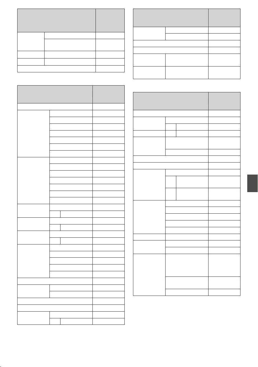
Function
P:
Available
-: Not
available
IRIS MANUAL, AUTO
P
AUTO IRIS LEVEL,
MANUAL IRIS LEVEL
P
ZOOM WIDE, STOP, TELE P F
FOCUS NEAR, STOP, FAR P F
H.PHASE
P
RM-LP20G
Function
P: Available
-: Not
available
MODE (BARS)
P
SHUTTER NORMAL
P
1/100*1, 1/120*2
P
1/250
P
1/500
P
1/1000
P
1/2000
P
EEI
P
GAIN 0
P
3dB
P
6dB
P
9dB
P
12dB
P
18dB
P
ALC
P
DETAIL
P
- LEVEL
P
GAMMA
P
- LEVEL
P
AUTO KNEE
P
- KNEE POINT
P
WHITE
BALANCE
MODE
MANUAL
P
PRESET
P
FAW
P
AW A
P
AW B
P
PAINT
P
WHITE
PAINT
R(LEVEL)
P
B(LEVEL)
P
AUTO WHITE -
MASTER BLACK
P
IRIS AUTO/MANUAL
P
- LEVEL
P
Function
P: Available
-: Not
available
TALLY (LED) (RED: PGM)
P
(GREEN: PVM)
P
PREVIEW -
CALL*4
P
TALLY(PGM)
*4
Rear Input
P
TALLY(PVW)
*4
Rear Input
P
RM-HP790DU/RM-HP790DE
Function
P: Available
-: Not
available
MODE (BARS)
P
DETAIL
(CONTOUR)
P
- LEVEL
P
DETAIL BAL H/V
P
DTL FRQ LOW, MIDDLE,
HIGH
P
AUTO -
SKIN DTL
P
FULL AUTO SHOOTING
P
IRIS
P
- MANUAL
LEVEL
P
- AUTO IRIS
LEVEL
P
WHITE
BALANCE
MANUAL
P
PRESET
P
AUTO1
P
AUTO2
P
FAW
P
PAINT R, B
P
AUTO SET -
WHITE
P
GAIN 0dB, +3dB, +6dB,
+9dB, +12dB,
+15dB, +18dB,
ALC+EEI, ALC
P
+24dB, -3dB,
VARIABLE GAIN
P
LOLUX
P
Functions Operable from the Remote Control Unit
167
Connecting External Devices
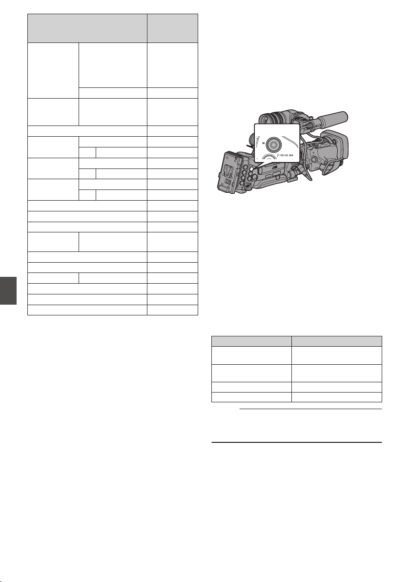
Function
P: Available
-: Not
available
SHUTTER OFF, 1/100*1,
1/120*2, 1/250,
1/500, 1/1000,
1/2000, 1/4000,
1/10000
P
V.SCAN -
BLACK NORMAL,
STRETCH,
COMPRESS
P
V.RESOLUTION (HI-RESO) -
AUTO KNEE
P
- KNEE POINT
P
GAMMA
P
- LEVEL
P
DNR
P
- LEVEL -
COLOR MATRIX -
SMOOTH TRANS
P
MASTER BLACK
P
ASPECT
RATIO
4:3, 16:9, LETTER -
H.PHASE
P
HD H.PHASE
P
SC COARSE 0°, 90°, 180°, 270° -
CALL*4
P
TALLY(PROGRAM)*4
P
TALLY(PREVIEW)*4
P
*1 Only when the frame rate of the [WFrame & Bit
Rate] and [YFrame & Bit Rate] items in the
[Record Format] menu of the camera recorder
is set to “60”, “30”, or “24”.
*2 Only when the frame rate of the [WFrame & Bit
Rate] and [YFrame & Bit Rate] items in the
[Record Format] menu of the camera recorder
is set to “50” or “25”.
*3 “Normal” when both [Stretch] and [Compress]
are set to “Off”.
*4 Available only when [System] B [Tally
System] is set to “Studio” during startup.
Inputting SDI Signals from
an External Device
A
B
The camera recorder comes equipped with a [SDI
IN] terminal on the side, which enables HD/SD SDI
signals from an external device to be recorded to
the SD card.
.
HD/SD SDI IN
1
Set the camera recorder to the Camera
mode.
(A P18 [Operation Modes] )
2
Set [System] to “HD(SDI In)” or “SD(SDI
In)”.
Set [Main Menu] B [System] B [Record Set] B
[Record Format] B [System] to “HD(SDI In)” or
“SD(SDI In)”.
3
Input SDI signals from the external device
to the [SDI IN] terminal.
4
Set the [Record Format] item.
Set each item according to the selected
[System] item.
(A P132 [ Record Format ] )
SDI Input Signal
W Resolution
1080/59.94i
1080/50i
1920×1080
1440×1080
720/59.94p
720/50p
1280×720
480/59.94i 720×480 (U model)
576/50i 720×576 (E model)
Memo :
0
When a signal with a recording format other than
those stated in the table is input, “Invarid Sync”
will be displayed.
168
Functions Operable from the Remote Control Unit
Connecting External Devices
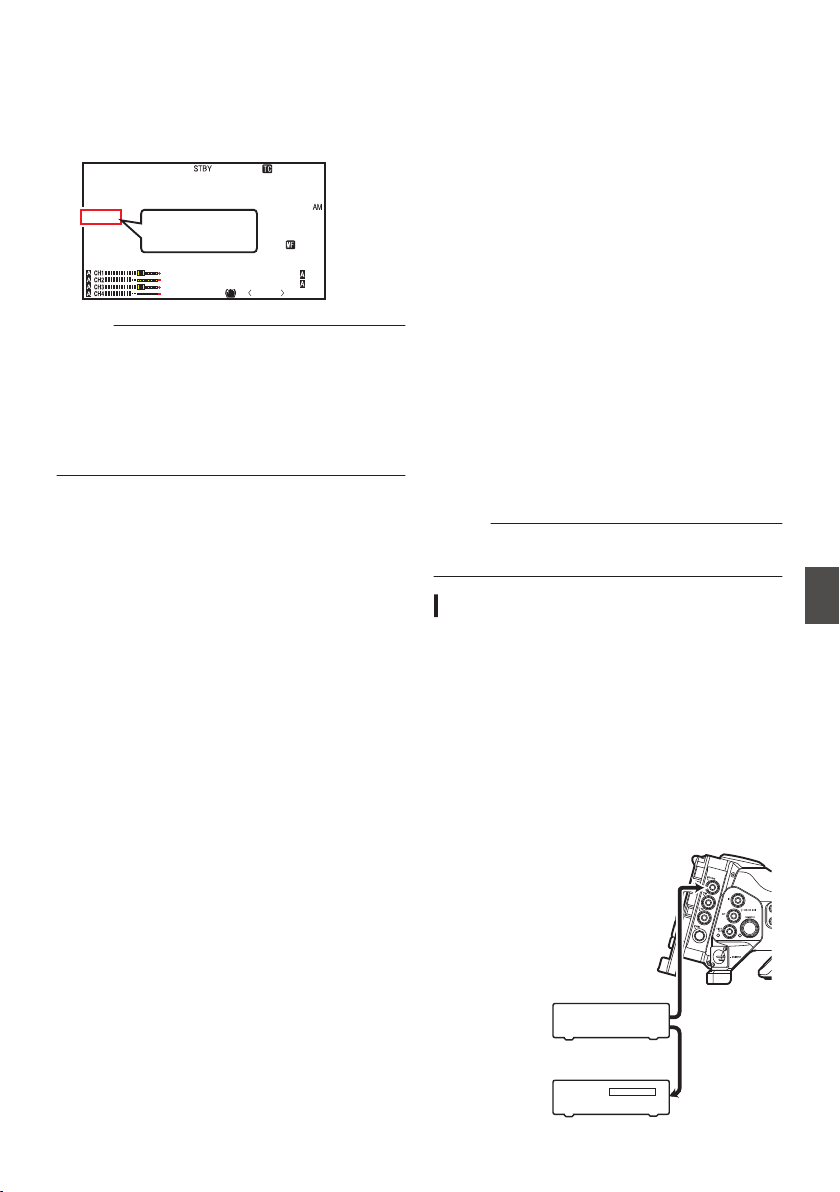
5
Start and stop recording on the camera
recorder.
0
The input signals are output in the HD-
SDI/SD-SDI format from the video output
terminals.
0
“SDI IN Z” appears on the display screen.
.
P13000K
1/100
F1. 6
0dB
AE+6
ND 1 /6 4
12 :34 : 56
Jan 24,2014
00:00: 00.00
5 . 6 f t
SDI IN Z
SDI IN
Z
Memo :
0
Checking of the recording (clip review) is
disabled while you are recording external video
signals.
0
Do not disconnect the cables connecting to the
input terminal while recording is in progress.
0
The “Z” mark blinks when the format of the input
signal is different from the format selected in
step 4, or when there is no signal input.
Inputting External
Synchronizing Signals
(Genlock)
0
A [GENLOCK] terminal is available on the side
of the camera recorder.
0
You can input synchronizing signals from a
KA-M790G unit (Multicore Remote Adapter:
sold separately) that is connected to the
accessory connection terminal (68 pins) on the
rear of the camera recorder. A B
0
SDI signals (digital signals) can be input from the
[HD/SD SDI IN] terminal on the side. A B
0
Input external synchronizing signals from the
[GENLOCK] terminal and [HD/SD SDI IN]
terminal (A B), and synchronize the
camera video or playback image with the
external signal.
0
The H (Horizontal) Phase of the camera
recorder’s video signals can be adjusted with
respect to the external synchronizing signals on
the [A/V Set] B [Video Set] B [Genlock Adjust]
screen.
(A P126 [ Genlock Adjust ] )
Memo :
0
The genlock feature is only usable in the Camera
mode.
Genlock Signal Settings
For analog signal input
o Synchronizing signal used
SD synchronizing
signal
:
BB (Black Burst) signal
Supports SMPTE170M
(RS-170A)-NTSC
Supports ITU-R BT.470-6 PAL
HD synchronizing
signal
:
HDTV tri-level synchronizing
signal
Supports SMPTE296M-HD720p
Supports SMPTE274M-
HD1080i
.
GENLOCK
Video
Equipment
External Synchronizing Signal
External Synchronizing Signal
SYNC Signal
Generator
Inputting SDI Signals from an External Device A B
169
Connecting External Devices
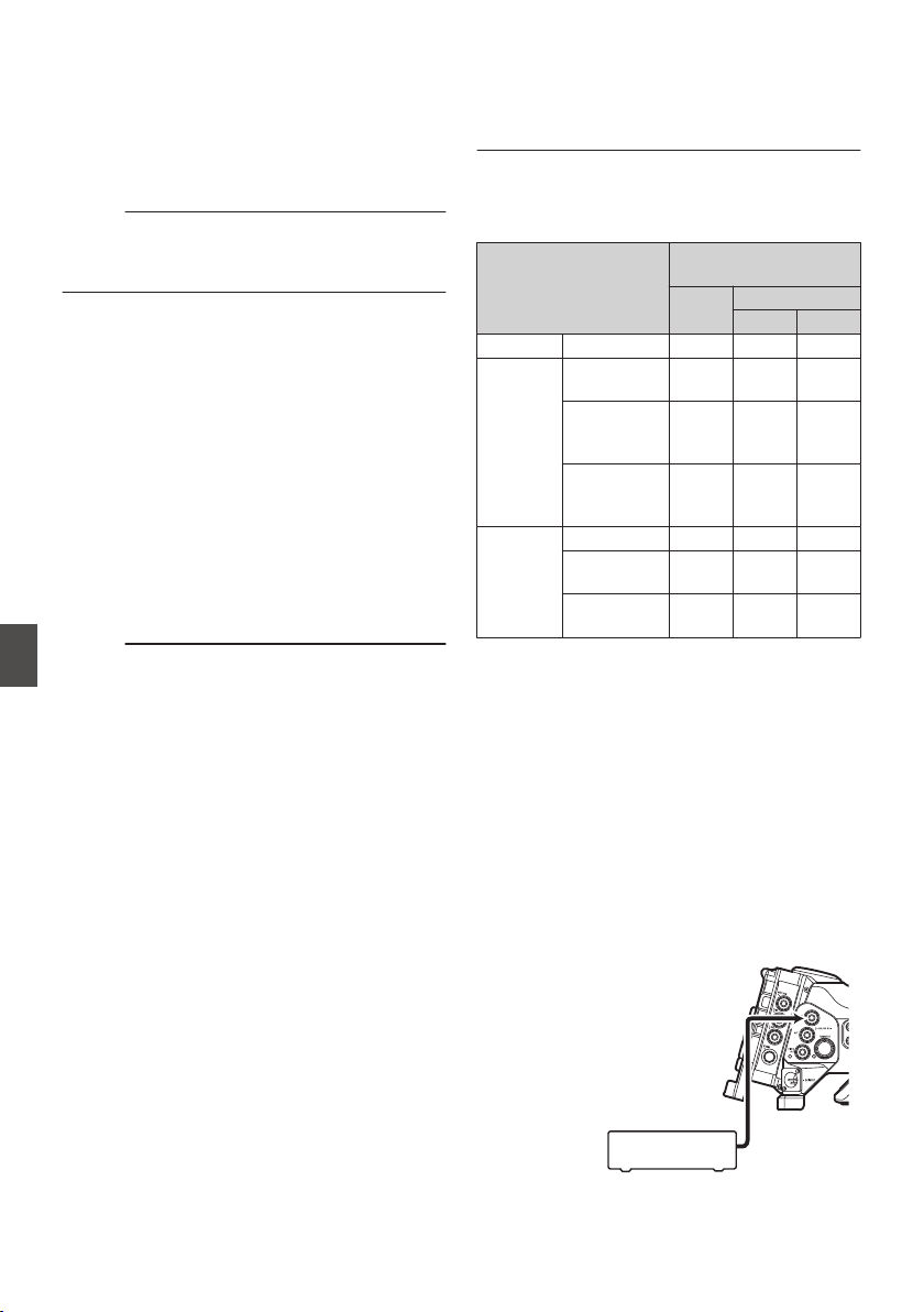
1
Set the camera recorder to the Camera
mode.
(A P18 [Operation Modes] )
2
Set [Genlock Input] to “BNC”.
A B
Set [A/V Set] B [Video Set] B [Genlock Input] to
“BNC”.
(A P126 [ Genlock Input A B ] )
Memo :
0
Set to “Adapter” to input synchronizing signal
from the accessory connection terminal (68
pins) on the rear of this unit.
3
When in the standby or stop mode, input
synchronizing signals from the SYNC
signal generator to the [GENLOCK]
terminal.
0
When the camera recorder’s video is locking
to the external synchronizing signal, “Sync
Locking” appears on the screen.
0
After locking to the external synchronizing
signal is complete, the display disappears
and recording can be performed.
0
If genlock is disconnected due to reasons
such as no signal input while genlock is in
operation, “Sync Unlocked” is displayed.
0
If there is genlock signal input but the signal
format is not supported, “Invalid Sync” is
displayed.
Memo :
0
If the frame rate of [WFrame & Bit Rate]/
[YFrame & Bit Rate] in the [Record Format]
menu is set to “60p”, “60i”, “30p”, or “24p”,
59.94 Hz synchronizing signals (vertical
synchronization) are input.
50 Hz/60 Hz synchronizing signals are not
synchronized.
0
If the frame rate of [WFrame & Bit Rate]/
[YFrame & Bit Rate] in the [Record Format]
menu is set to “50p”, “50i”, or “25p”, 50 Hz
synchronizing signals (vertical synchronization)
are input.
59.94 Hz/60 Hz synchronizing signals are not
synchronized.
(A P133 [ W Frame & Bit Rate ] )
(A P134 [ Y Frame & Bit Rate ] )
0
Do not connect or disconnect the input cable for
the synchronizing signals during recording or
playback
0
If the power is turned on during input of external
synchronizing signals, vertical oscillation may
occur. This is not a malfunction.
0
Signals such as VTR playback signals with
jitters may not be synchronized on this camera
recorder.
0
Only H (Horizontal) and V (Vertical) genlock
functions are available on this camera recorder.
It does not come with a lock function for SC (sub-
carrier). Color flash may occur during switching
such as when composite signals are used by a
switcher.
o Phase Items to Synchronize
The phase items to be synchronized may vary
depending on the input synchronizing signal and
output video signal.
Output Video Signal
Input Synchronizing
Signal
BB Tri-sync
720p 1080i
VIDEO Composite H, V, F V V, F
Y/PB/PR
A
B
SD
Component
H, V, F V V, F
HD
Component
720p
V H, V V
HD
Component
1080i
V, F V H, V, F
HD/SD
SDI
SD-SDI H, V, F V V, F
HD-SDI
720p
V H, V V
HD-SDI
1080i
V, F V H, V, F
H : Horizontal Phase
V : Vertical Phase
F : Field Phase
For digital signals (SDI) input
A B
Input external synchronizing signals from the
[HD/SD SDI IN] terminal, and synchronize the
camera video or playback image with the external
signal.
o Synchronizing signal used
SD synchronizing
signal
: Supports SMPTE259M
HD synchronizing
signal
: Supports SMPTE292M
.
HD/SD SDI IN
External Synchronizing Signal
SDI Signal
Generator
170
Inputting External Synchronizing Signals (Genlock)
Connecting External Devices
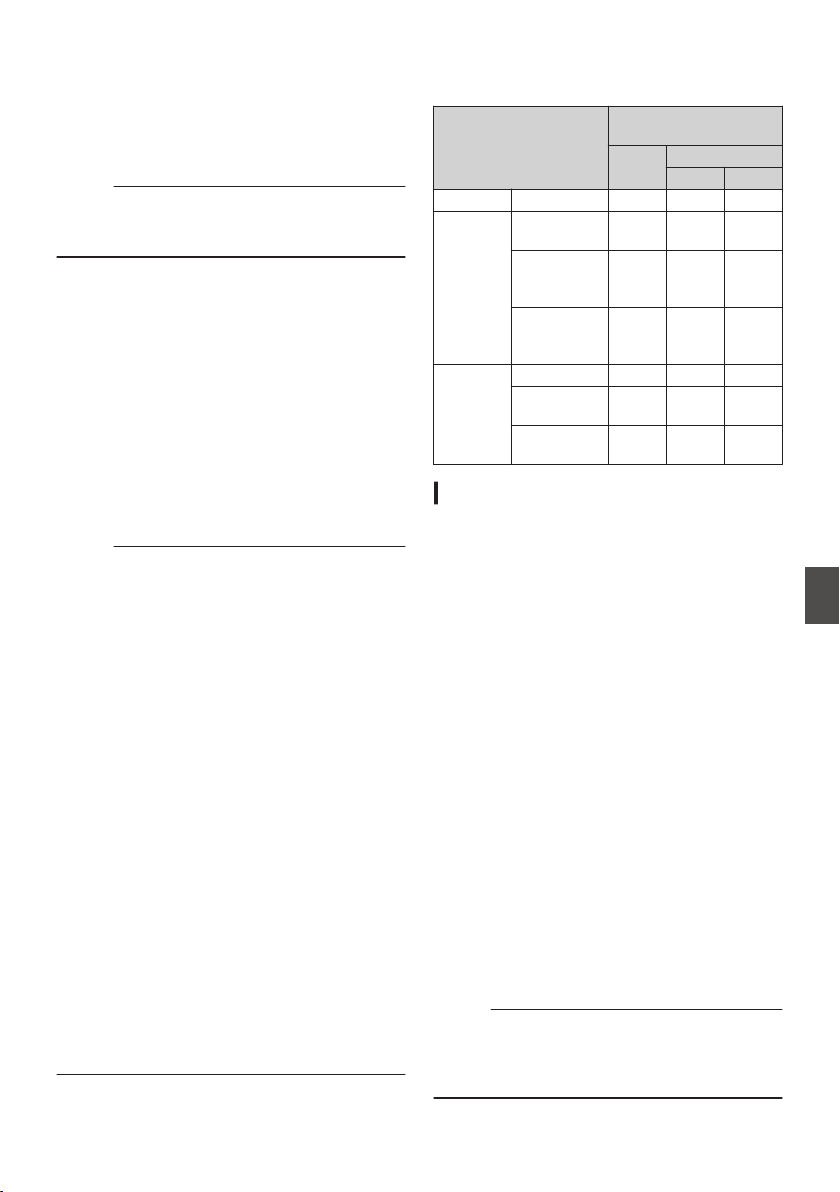
1
Set the camera recorder to the Camera
mode.
(A P18 [Operation Modes] )
2
Set [Genlock Input] to “SDI”.
Set [A/V Set] B [Video Set] B [Genlock Input] to
“SDI”.
(A P126 [ Genlock Input A B ] )
Memo :
0
Set to “Adapter” to input synchronizing signal
from the accessory connection terminal (68
pins) on the rear of this unit.
3
When in the standby or stop mode, input
synchronizing signals from the SDI signal
generator to the [HD/SD SDI IN] terminal.
0
When the camera recorder’s video is locking
to the external synchronizing signal, “Sync
Locking” appears on the screen.
0
After locking to the external synchronizing
signal is complete, the display disappears
and recording can be performed.
0
If genlock is disconnected due to reasons
such as no signal input while genlock is in
operation, “Sync Unlocked” is displayed.
0
If there is genlock signal input but the signal
format is not supported, “Invalid Sync” is
displayed.
Memo :
0
If the frame rate of [WFrame & Bit Rate]/
[YFrame & Bit Rate] in the [Record Format]
menu is set to “60p”, “60i”, “30p”, or “24p”,
59.94 Hz synchronizing signals (vertical
synchronization) are input.
50 Hz/60 Hz synchronizing signals are not
synchronized.
0
If the frame rate of [WFrame & Bit Rate]/
[YFrame & Bit Rate] in the [Record Format]
menu is set to “50p”, “50i”, or “25p”, 50 Hz
synchronizing signals (vertical synchronization)
are input.
59.94 Hz/60 Hz synchronizing signals are not
synchronized.
(A P133 [ W Frame & Bit Rate ] )
(A P134 [ Y Frame & Bit Rate ] )
0
Do not connect or disconnect the input cable for
the synchronizing signals during recording or
playback
0
If the power is turned on during input of external
synchronizing signals, vertical oscillation may
occur. This is not a malfunction.
0
Signals such as VTR playback signals with
jitters may not be synchronized on this camera
recorder.
0
Only H (Horizontal) and V (Vertical) genlock
functions are available on this camera recorder.
It does not come with a lock function for SC (sub-
carrier). Color flash may occur during switching
such as when composite signals are used by a
switcher.
o Phase Items to Synchronize
The phase items to be synchronized may vary
depending on the input synchronizing signal and
output video signal.
Output Video Signal
Input Synchronizing
Signal
SD-
SDI
HD-SDI
720p 1080i
VIDEO Composite H, V, F V V, F
Y/PB/PR
A
B
SD
Component
H, V, F V V, F
HD
Component
720p
V H, V V
HD
Component
1080i
V, F V H, V, F
HD/SD
SDI
SD-SDI H, V, F V V, F
HD-SDI
720p
V H, V V
HD-SDI
1080i
V, F V H, V, F
Adjusting H Phase
1
Select [Genlock Adjust] in the [A/V Set]
menu.
Adjust the [A/V Set] B [Video Set] B Genlock
Adjust item as follows.
(A P126 [ Genlock Adjust ] )
[Analog SD H Phase] : Adjusts the H Phase
of the SD analog
signal.
[Analog HD H Phase]
A B
: Adjusts the H Phase
of the HD analog
signal.
[SD-SDI H Phase] : Adjusts the H Phase
of the SD SDI signal.
[HD-SDI H Phase] : Adjusts the H Phase
of the HD SDI signal.
2
Select a value using the cross-shaped
buttons (
JK).
0
The H Phase of the camera recorder’s video
signal is adjusted with respect to the external
synchronizing signal input from the
[GENLOCK] terminal.
0
The setting value of the [Analog HD H
Phase] A B, [SD-SDI H Phase], and
[HD-SDI H Phase] items can be adjusted in
increments of 10 by pressing the cross-
shaped button (JK) for 2 seconds or longer.
Memo :
0
Adjustment cannot be made while recording or
playback is in progress.
0
The video image may be disrupted momentarily
during adjustment. This is not a malfunction.
Inputting External Synchronizing Signals (Genlock)
171
Connecting External Devices

Displaying Return Videos
from an External Device
A B
Return video from an external device (switcher,
etc.) can be displayed on the viewfinder or LCD
monitor of the camera recorder.
(A P127 [ Return Input A B ] )
Memo :
0
This feature is only usable in the Camera mode.
1
Set the camera recorder to the Camera
mode.
(A P18 [Operation Modes] )
2
Assign the “Return Video” function to any
of the user buttons.
(A P42 [Assignment of Functions to User
Buttons] )
* This excludes the [AUTO FOCUS/11] button.
3
Select the way the return video is to be
displayed.
Set using [Main Menu] B [Camera Function] B
[User Switch Set] B [Return Video].
(A P113 [ Return Video ] )
4
Select the input destination of the return
video.
The input destination of the return video can be
set using the [A/V Set] B [Video Set] B [Return
Input] item.
(A P127 [ Return Input A B ] )
5
Select the aspect ratio of the return video.
Set using [A/V Set] B [Video Set] B [Return
Aspect].
(A P127 [ Return Aspect A B ] )
6
Press the user button that is assigned with
the “Return Video” function.
0
By pressing the user button assigned with
the “Return Video” function, the captured
image or return video is displayed according
to the method specified in step 3.
Memo :
0
When the return video is displayed in full screen,
the following displays and operations are
disabled.
0
Zebra display
0
Skin Detail operation
0
Spot Meter display
0
Focus Assist feature (ACCU-Focus
operation)
0
Aspect Marker display
0
Safety Zone display
0
Center Mark display
0
During display of PiP and return video in full
screen, the [LCD Mirror] setting becomes invalid
and is set automatically to “Normal”.
(A P120 [ LCD Mirror ] )
Studio System A B
Details of the Studio Terminal
Connect to the [STUDIO] terminal (10-pin) when
you are combining the use of devices such as a
transmission unit manufactured by a different
company.
PIN No. Signal Name
Input/
Output
1 NC -
2 CALL TALLY IN
3 RM TALLY OUT
4 RM PREVIEW OUT
5 NC -
6 NC -
7 TALLY IN IN
8 RETURN GND -
9 RETURN IN IN
10 GND -
172
Displaying Return Videos from an External Device A B
Connecting External Devices
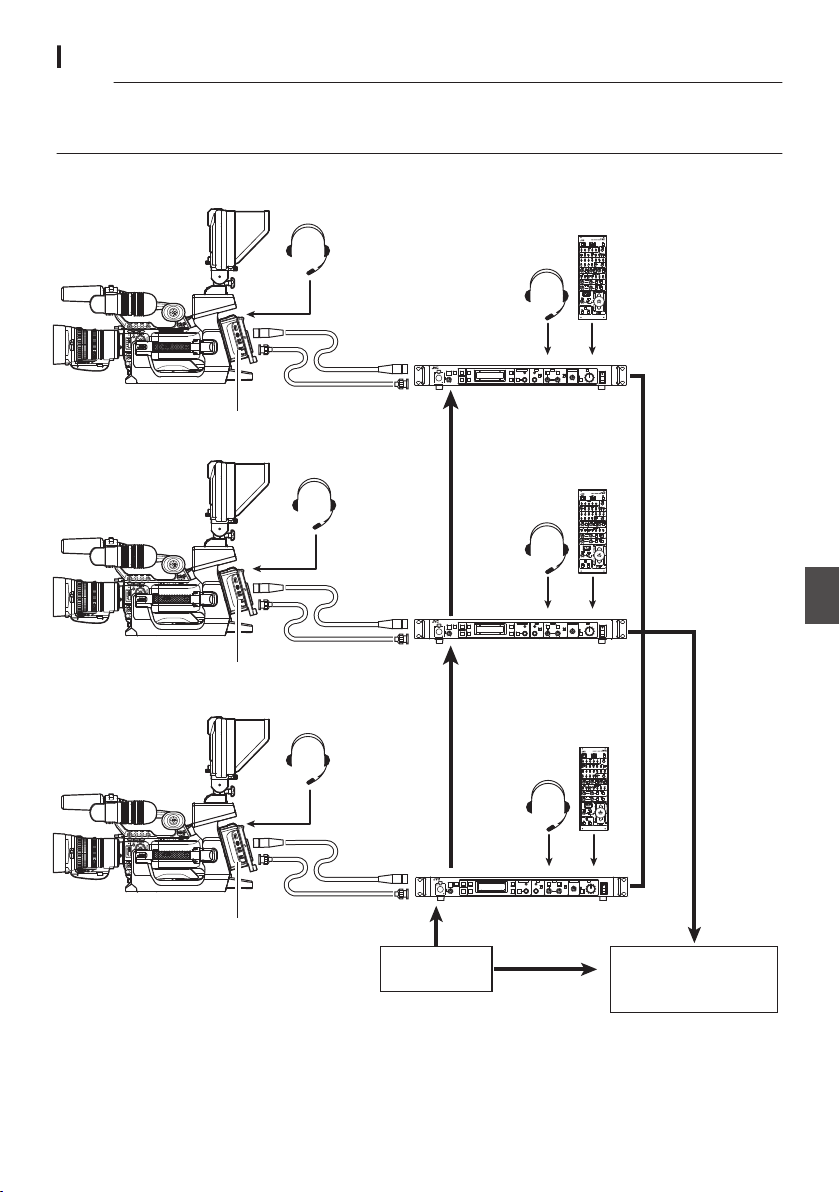
Studio System Connection Example
Memo :
0
For details on the connection with a remote control unit, please refer to the instruction manual for the
remote control unit.
0
VF-HP840U does not function even when it is connected to this camera recorder.
.
CALLTALLY
INTERCOM
LEVEL
F3
MENU/SHUTTER GAIN
PAINT AUTO
BR
W.BAL
AUTO
MANU
WHITE MASTER BLACK
POWER
I
O
IRIS
STEP
SHUTTER
MENU
PUSH-ON
DOWN UP
VARIABL E
PUSH-ON
HIGH
LOW
B
A
PRESET
CLOSE OPEN
MID
DOWN UP
F4
REMOTE CONTROL UNIT RM-P790
FULL AUTO F1
SHUTTER
GAIN
F2
BARS
CALLTALLY
INTERCOM
LEVEL
F3
MENU/SHUTTER GAIN
PAINT AUTO
BR
W.BAL
AUTO
MANU
WHITE MASTER BLACK
POWER
I
O
IRIS
STEP
SHUTTER
MENU
PUSH-ON
DOWN UP
VARIABL E
PUSH-ON
HIGH
LOW
B
A
PRESET
CLOSE OPEN
MID
DOWN UP
F4
REMOTE CONTROL UNIT RM-P790
FULL AUTO F1
SHUTTER
GAIN
F2
BARS
CALLTALLY
INTERCOM
LEVEL
F3
MENU/SHUTTER GAIN
PAINT AUTO
BR
W.BAL
AUTO
MANU
WHITE MASTER BLACK
POWER
I
O
IRIS
STEP
SHUTTER
MENU
PUSH-ON
DOWN UP
VARIABL E
PUSH-ON
HIGH
LOW
B
A
PRESET
CLOSE OPEN
MID
DOWN UP
F4
REMOTE CONTROL UNIT RM-P790
FULL AUTO F1
SHUTTER
GAIN
F2
BARS
Studio Viewfinder
VF-HP790G
Multicore Remote Adapter
KA-M790G
Studio Adapter KA-790G
RM-LP25U
RM-LP25U
RM-LP25U
Studio Viewfinder
VF-HP790G
Multicore Remote Adapter
KA-M790G
Studio Adapter KA-790G
RM-HP790DU/RM-HP790DE*
RM-HP790DU/RM-HP790DE*
RM-HP790DU/RM-HP790DE*
Studio Viewfinder
VF-HP790G
Multicore Remote Adapter
KA-M790G
Studio Adapter KA-790G
VC-P110U (5m)
VC-P112U (20m)
VC-P113U (50m)
VC-P114U (100m)
VC-P110U (5m)
VC-P112U (20m)
VC-P113U (50m)
VC-P114U (100m)
VC-P110U (5m)
VC-P112U (20m)
VC-P113U (50m)
VC-P114U (100m)
Switcher
External
Synchronizing Signal
HD/SD SDI
Component
Camera Remote Control Unit
Camera Remote Control Unit
Camera Remote Control Unit
Remote Control Unit
Remote Control Unit
Remote Control Unit
26Pin Camera Cable
Coaxial cable
Coaxial cable
Coaxial cable
26Pin Camera
Cable
26Pin Camera
Cable
Headset
(Beyerdynamic)
Headset
(Beyerdynamic)
Headset
(Beyerdynamic)
Headset
(Beyerdynamic)
Headset
(Beyerdynamic)
Headset
(Beyerdynamic)
* Models with an E suffix are for the European market and the UL Listing mark is not applicable.
Studio System A B
173
Connecting External Devices

Functions of Network
Connection
0
The network function can be operated by
connecting one of the following adapters to the
rear [HOST] terminal.
0
Wireless LAN adapter
0
Ethernet adapter
0
Cellular adapter
(A P175 [Camera Setup for Network
Connection] )
0
The network feature comprises web-browser-
based functions using devices such as a
smartphone, tablet terminal, or PC, as well as
FTP and live streaming functions that run via
thumbnail screens and menu operation.
List of Functions
Importing Metadata
You can download a metadata settings file (XML
format) from the FTP server and store metadata in
the camera recorder.
(A P178 [Importing Metadata] )
Uploading Recorded Clips
You can upload clips recorded in the SD card to a
preset FTP server.
(A P180 [Uploading a Recorded Video Clip] )
Memo :
0
Uploading can also be performed via a web
browser.
(A P187 [Uploading a Recording Clip via a Web
Browser] )
Editing Metadata
0
Planning Metadata
You can access the page for editing the camera
recorder’s metadata via a web browser on
devices such as a smartphone, tablet terminal,
or PC, and edit the metadata that is to be applied
to clips to be recorded.
(A P183 [ Planning Metadata ] )
0
Clip Metadata
You can access the page for editing the
metadata via a web browser on devices such as
a smartphone, tablet terminal, or PC, and
display or rewrite the metadata that is recorded
to a clip.
(A P184 [ Clip Metadata ] )
View Remote
You can access via a web browser on devices such
as a smartphone, tablet terminal, or PC to check
the live image and perform remote control
operations of the camera.
(A P190 [View Remote Feature] )
Camera Control
You can access via a web browser on devices such
as a smartphone, tablet terminal, or PC to remotely
control the camera.
(A P193 [Camera Control Function] )
Live streaming
By combining with a decoder device or PC
application that support live streaming, you can
perform audio and video streaming via the network.
(A P199 [Performing Live Streaming] )
Preparing Network
Connection
Operating Environment
Computer
o CPU
Core 2 Duo 2.4 GHz or higher
o Memory
2 GB or higher
o Display
1024x768 or higher
o OS
0
Windows XP SP3/Windows Vista SP2 (32bit/
64bit)/Windows7 SP1 (32bit/64bit)/Windows
8.1 (32bit/64bit)
0
Mac OS X v10.5 or later
o Web Browser
0
Internet Explorer 8 or later
0
Safari 6 or later
0
Google Chrome 31 or later
0
Mozilla Firefox 25 or later
Smartphone/Tablet Terminal
o iPhone/iPad/iPod touch
iOS 6 or later, screen resolution of 960 x 640 dots
or higher (Safari 6 or later)
o Android Smartphone/Tablet
Android 4.0 or later, screen resolution of 1280 x 800
dots or higher (standard browser or Chrome)
174
Functions of Network Connection
Connecting to the Network
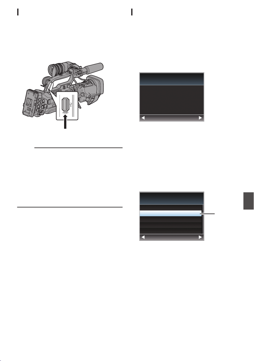
Camera Setup for Network Connection
1
Connect an appropriate adapter according
to the intended use to the [HOST] terminal
at the rear of the camera recorder.
The following adapters can be connected.
0
Wireless LAN adapter
0
Ethernet adapter
0
Cellular adapter
.
Connect an appropriate adapter
Memo :
0
Only a network connection adapter can be
connected to the [HOST] terminal.
0
Connect or disconnect an adapter only after you
have turned off the power of the camera
recorder.
0
You can find the latest information on the
compatible adapters at the product page of our
website.
0
Two types of network coverage (WAN and LAN)
are available for each application.
2
Enable the network connection.
Set [Main Menu] B [System] B [Network] to
“On(HDMI Off)” or “On(SDI Off)”.
3
Configure the connection settings.
0
Select [Main Menu] B [System] B [Network]/
[Settings] B [Connection Setup] B [Wizard]
and press the Set button (R).
0
A wizard screen appears according to the
type of adapter connected. Follow the
instructions on the screen to perform setting.
(A P175 [Connecting via Wireless LAN] )
(A P177 [Connecting via Wired LAN] )
(A P177 [Connecting via Cellular Adapter] )
Connecting via Wireless LAN
Connection via Access Point
1
Perform setting on the camera recorder,
and start up the [Wizard] screen.
(A P175 [Camera Setup for Network
Connection] )
2
[Wireless LAN] appears on the [Wizard]
screen.
.
Back Next
Wireless LAN
Available Adapter
3
Press the
I button to display the [Select
Connection Type] screen.
Select “Connect with Access Point”.
Follow the screen instructions to complete
setting. Perform setting for the following.
0
Mode of connection
0
Method of setting
* SSID, type of encryption, Passphrase, and
IP Address setting (“DHCP” or “Manual”) in
cases other than WPS
.
3
Back Next
Connect with Access Point
P2P
Select Connection Type
4
Setting is complete.
After setting is complete, you can access the
camera recorder via a web browser.
(A P182 [Connecting from a Web Browser] )
Preparing Network Connection
175
Connecting to the Network
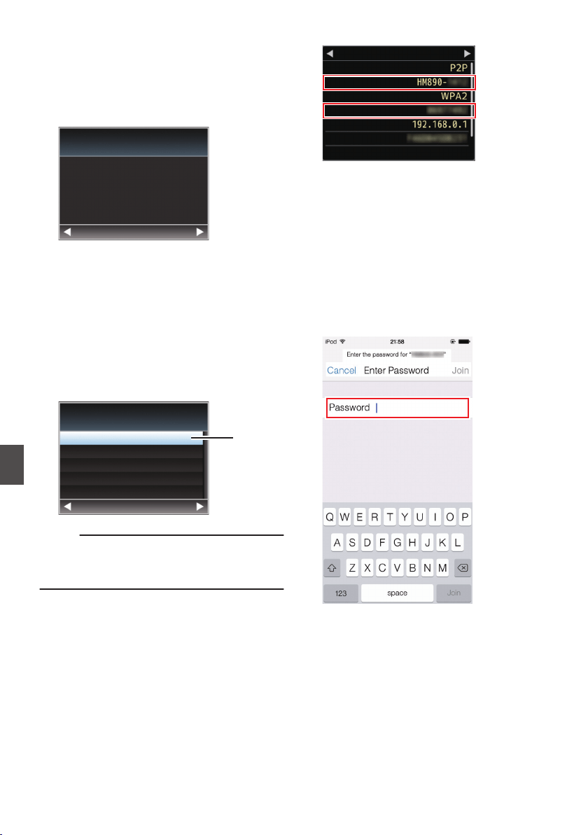
P2P Connection
You can access the web function of this camera
recorder from devices such as a smartphone,
tablet terminal, or PC.
1
[Wireless LAN] appears on the [Wizard]
screen.
.
Back Next
Wireless LAN
Available Adapter
2
Press the
I button to display the [Select
Connection Type] screen.
Select “P2P”.
Follow the screen instructions to complete
setting.
Perform setting for the following.
0
Mode of connection
0
Method of setting
* SSID and Passphrase in cases other than
WPS
.
2
Back Next
Connect with Access Point
P2P
Select Connection Type
Memo :
0
When “WPS” is selected in the [Select Setup
Type] screen, the following steps 3 and 4 are not
required.
3
Set the camera recorder to the Camera
mode, and display the [Network] (status)
screen.
0
Press the [STATUS] button on the camera
recorder to display the status screen.
Press the cross-shaped button (HI) to
display the [Network] screen.
0
Check to ensure that the SSID and
Passphrase that you have set in the wizard
are displayed.
.
SSID
Live Streaming
MAC Address
IP Address
Passphrase
Security Type
Ty p e
Network
4
Select SSID from the list of access points
(smartphone, tablet terminal, PC, etc.), and
enter Passphrase.
0
Display a list of the access points in the
wireless connection settings of the
smartphone, tablet terminal or PC, and
select “HM890--*****” or “HM850--*****”.
(***** are numbers that vary with the device
used.)
0
After the password confirmation screen
appears, enter the [Passphrase] displayed
on the [Network] screen.
.
5
Setting is complete.
After setting is complete, you can access the
camera recorder via a web browser.
(A P182 [Connecting from a Web Browser] )
176
Preparing Network Connection
Connecting to the Network

Connecting via Wired LAN
You can connect a device such as a smartphone,
tablet terminal, or PC to the camera recorder using
an Ethernet hub to access the camera recorder’s
web functions. Alternatively, you can also connect
directly using a cross cable.
1
Attach the Ethernet adapter to the [HOST]
terminal on the camera recorder, then
connect to the smartphone, tablet terminal,
or PC with an Ethernet hub or a cross cable.
2
Perform setting on the camera recorder,
and start up the [Wizard] screen.
(A P175 [Camera Setup for Network
Connection] )
3
[Ethernet] appears on the [Wizard] screen.
.
Back
Next
Ethernet
Available Adapter
4
Press the
I button to display the [IP
Address Configuration] screen.
Follow the screen instructions to complete
setting. Perform setting for the following.
0
IP address setting method (DHCP or
manual)
0
IP Address
0
Subnet Mask
0
Gateway
0
DNS Server
.
DHCP
Back Next
Manual
IP Address Configuration
5
Setting is complete.
After setting is complete, you can access the
camera recorder via a web browser.
(A P182 [Connecting from a Web Browser] )
Connecting via Cellular Adapter
You can make use of the FTP function and live
streaming function by connecting a cellular adapter
to this camera recorder.
1
Connect the cellular adapter to the [HOST]
terminal of the camera recorder.
2
Perform setting on the camera recorder,
and start up the [Wizard] screen.
(A P175 [Camera Setup for Network
Connection] )
3
[Cellular] appears on the [Wizard] screen.
.
Back
Next
Celluar
Available Adapter
4
Press the
I button.
Follow the screen instructions to complete
setting. Perform setting for the following.
0
Connection phone number
0
User name
0
Password
Caution :
0
You can access the web functions via a web
browser on devices such as a smartphone,
tablet terminal, or PC only in a LAN environment.
0
Note that you may have to pay very high bills in
the case of pay-per-use contracts. Fixed price
contract is recommended if you are using the
network function.
0
Note that the use of improper settings may result
in expensive bills from the phone service
provider. Make sure that the setting is correct.
0
To avoid expensive bills due to the roaming
connection, you are recommended to use this
function by disabling the roaming contract.
0
There may be communication even when you
are not using the network function. Remove the
cellular adapter when the function is not in use.
Preparing Network Connection
177
Connecting to the Network
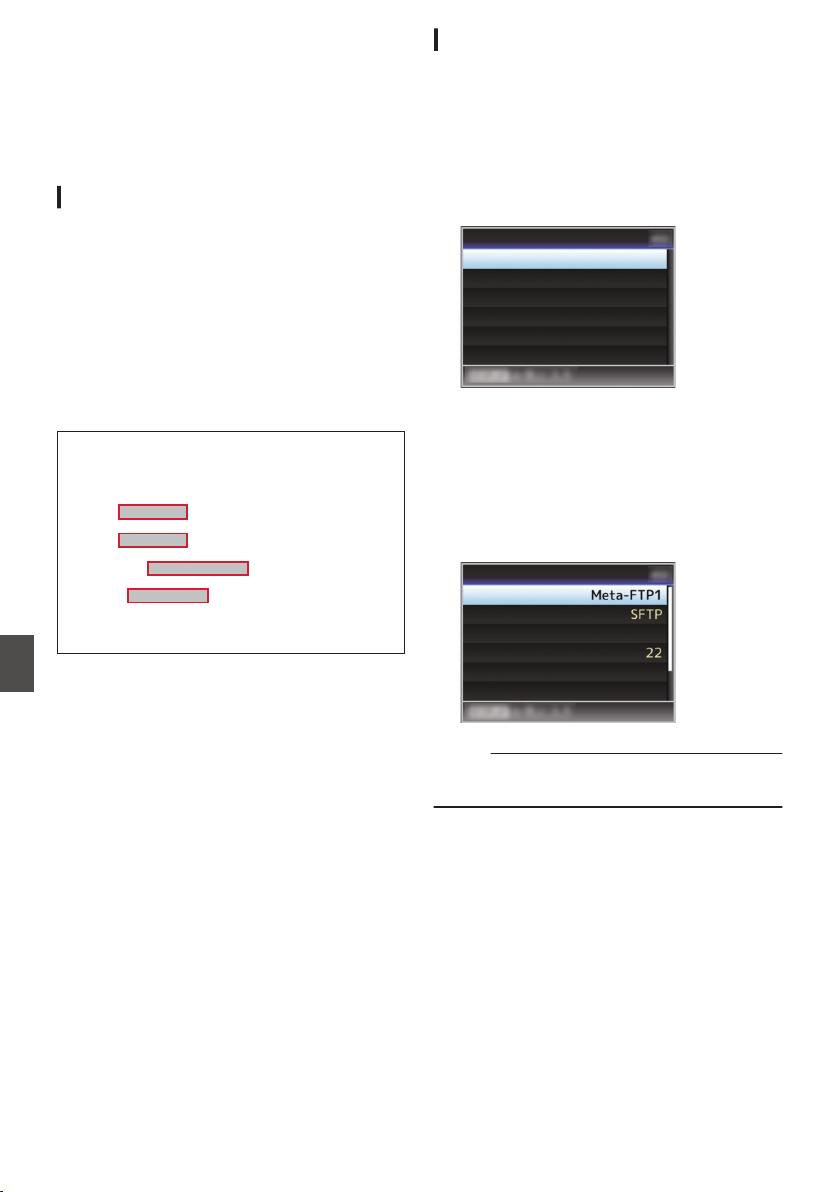
Importing Metadata
You can download a metadata settings file (XML
format) from the FTP server and store metadata in
the camera recorder.
The imported metadata is applied to clips to be
recorded.
Preparing Metadata
0
You can record the four metadata types below.
Title1 : ASCII only, max. 63 characters
(bytes)
Title2 : UNICODE, max. 127 bytes
Creator : UNICODE, max. 127 bytes
Description : UNICODE, max. 2047 bytes
0
Metadata makes use of the XML description
format.
0
Edit the <Title1>, <Title2>, <Description>,
<Creator> tag element using the XML editor.
(Indicated by the frames below)
.
<?xml version="1.0" encoding="UTF-8"?>
<NRT-MetaInterface lastUpdate="2014-01-26T18:06:21+09:00"
xmlns="urn:schemas-proHD:nonRealTimeMetaInterface:ver.1.00"
xmlns:xsi="http://www.w3.org/2001/XMLSchema-instance">
<MetaData>
<Title1>Title1 sample</Title1>
<!-- only "en",max63bytes -->
<Title2>Title2 sample</Title2>
<!-- ,max127bytes -->
<Description>Description sample</Description>
<!-- ,max2047bytes -->
<Creator>Creator sample</Creator>
<!-- ,max127bytes -->
</MetaData>
</NRT-MetaInterface>
Configuring the Server for Downloading
For specifying the settings (server name, user
name, password, etc.) for connecting to the FTP
server for downloading the metadata as well as the
path of the file to download.
1
Open the [Metadata Server] screen.
Open the [Main Menu] B [System] B [Network]/
[Settings] B [Metadata Server] screen.
.
Meta-FTP4...
Meta-FTP3...
Meta-FTP2...
Meta-FTP1...
Metadata Server
2
Register the [Metadata Server].
0
Select a server using the cross-shaped
button (JK), and press the Set button (R).
The server settings screen appears. Perform
setting for each item.
0
Up to 4 settings can be registered.
(A P140 [ Metadata Server ] )
.
Username
File Path
Port
Server
Protocol
Alias
Metadata Server Set
Memo :
0
For details on the registered information, please
consult the network administrator for the server.
178
Importing Metadata
Connecting to the Network
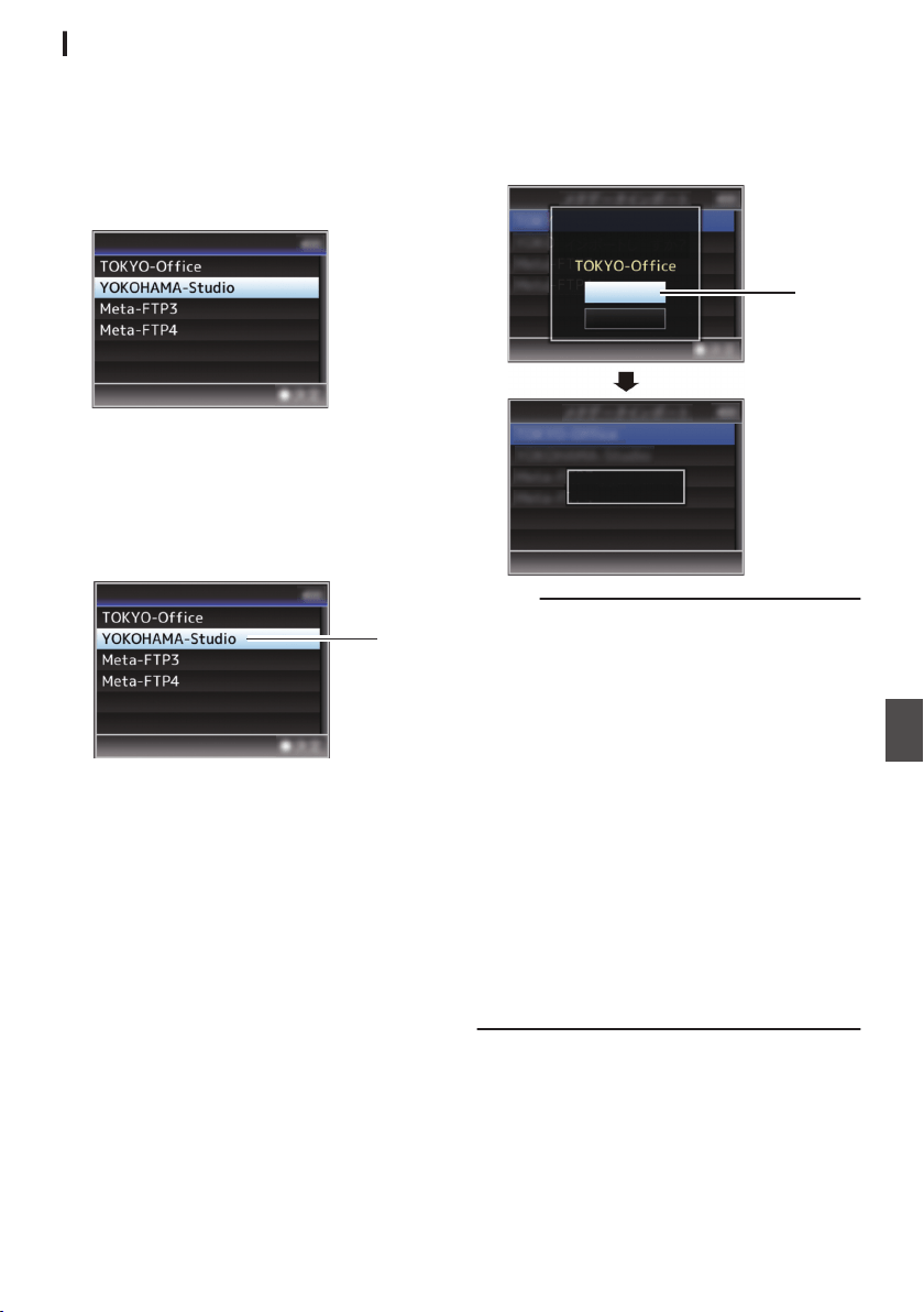
Importing Metadata
Download the metadata settings file (XML format)
from the FTP server.
1
Select [Main Menu]
B [System] B [Network]
B [Import Metadata] and press the Set
button (
R).
The [Import Metadata] screen appears.
.
Import Metadata
2
Select the server for importing the
metadata.
0
The name that is registered in [Metadata
Server] B [Alias] is displayed.
0
Select a server using the cross-shaped
button (JK), and press the Set button (R).
.
2
Import Metadata
3
Select [Import] on the confirmation screen,
and press the Set button (
R).
Import starts.
After import is complete, the display is restored
to the screen before the [Import Metadata]
screen appears.
.
3
Importing...
Cancel
Import
Import Metadata?
Memo :
0
You cannot exit the menu or perform recording
while import is in progress.
0
If import of the metadata failed, “Import Error!” is
displayed, and a message indicating the cause
of the error appears.
Press the Set button (R) to return to the [Import
Metadata] screen in step 1.
(A P203 [List of FTP Transfer Errors] )
0
When “HTTP” is selected in the [Select FTP
Proxy] screen of the network connection setting,
connections to the servers other than “FTP”
protocol cannot be made.
0
If a setting other than “FTP” is specified for
[Protocol], to ensure the safety of the
communication path, a screen appears
prompting you to validate the fingerprint of the
public key and certificate received from the
server.
Check to ensure that the displayed value
coincides with the known value.
Importing Metadata
179
Connecting to the Network
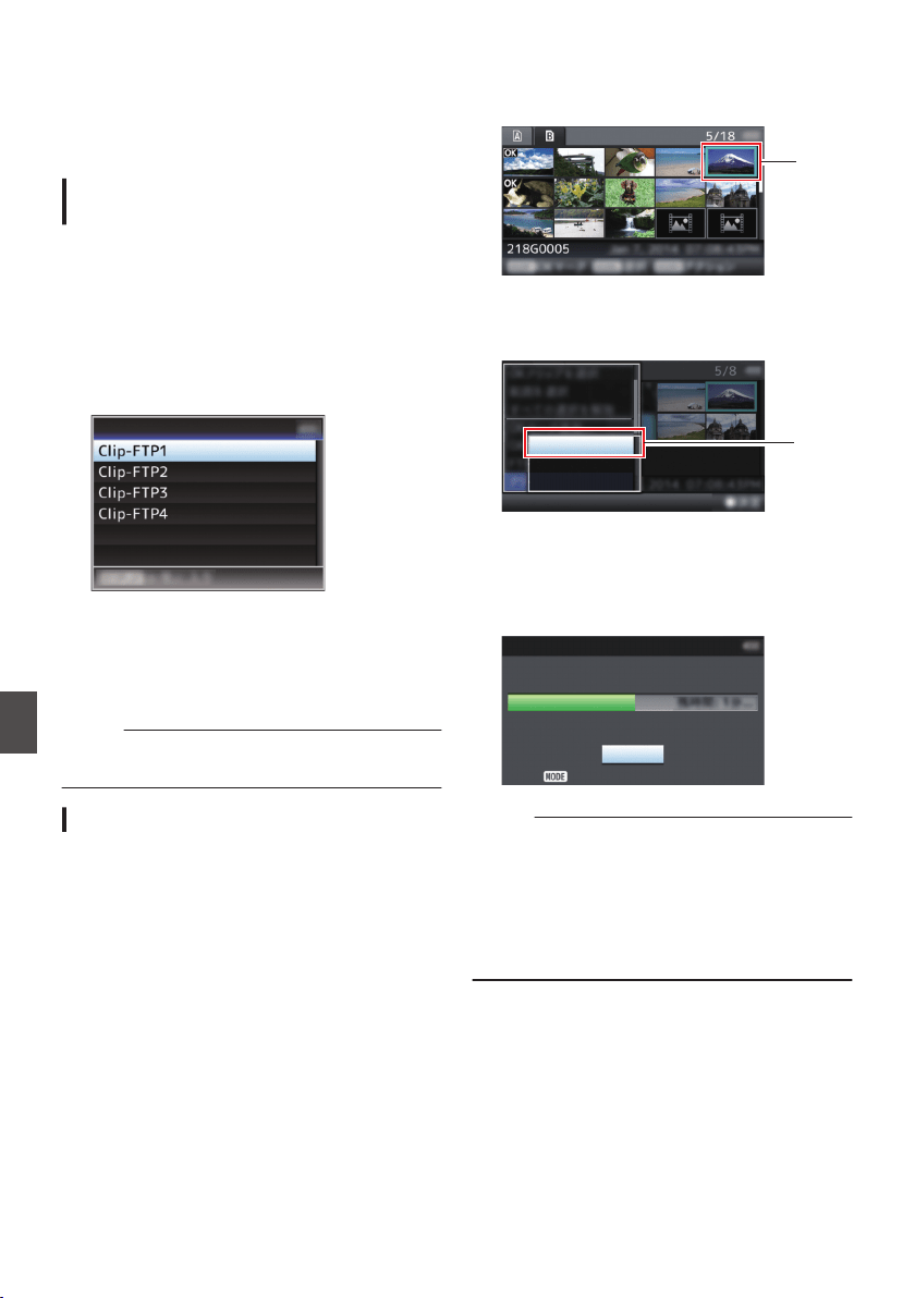
Uploading a Recorded
Video Clip
Upload clips recorded in the SD card to a preset
FTP server.
Configuring the FTP Server for
Uploading
For specifying the settings (server name, user
name, password, etc.) for connecting to the FTP
server to upload recorded clips to as well as the
directory of the upload destination.
1
Open the [Clip Server] screen.
Open the [Main Menu] B [System] B [Network]/
[Settings] B [Clip Server] screen.
.
Clip Server
2
Register the [Clip Server].
Register the server to upload recorded clips in
the SD card to.
Up to 4 servers can be registered.
(A P140 [ Clip Server ] )
Memo :
0
For details on the registered information, please
consult the network administrator for the server.
Uploading Video Clip
Upload clips recorded in the SD card to a preset
FTP server.
All playable clips on the thumbnail screen can be
uploaded.
Uploading a Video Clip
1
Set the camera recorder to the Media mode.
0
Press and hold the [CAM/MEDIA] selection
button in the Camera mode to enter the
Media mode. A thumbnail screen of the clips
recorded on the SD card is displayed.
0
You can upload the selected clips on the
thumbnail screen to the FTP server.
(A P94 [Thumbnail Screen] )
2
Move the cursor to the clip to be uploaded.
Move the cursor to the clip to be uploaded using
the cross-shaped button (JKH I).
.
2
3
Press the [LOAD FILE/3] button.
The action selection screen is displayed.
.
All Clips
Selected Clips
This Clip
3
4
Select [FTP Upload]
B [This Clip] B server
to upload to, and press the Set button (
R).
The status of the transfer process is indicated
by a progress bar.
.
Upload in Background
Stop
FTP Upload
Memo :
0
The name for the server to upload files to are
indicated using the preset names in [Clip
Server] B [Alias].
0
To stop uploading, press the Set button (R).
Select [Yes] on the confirmation screen, and
press the Set button (R) to stop uploading and
return to the thumbnail screen.
180
Uploading a Recorded Video Clip
Connecting to the Network
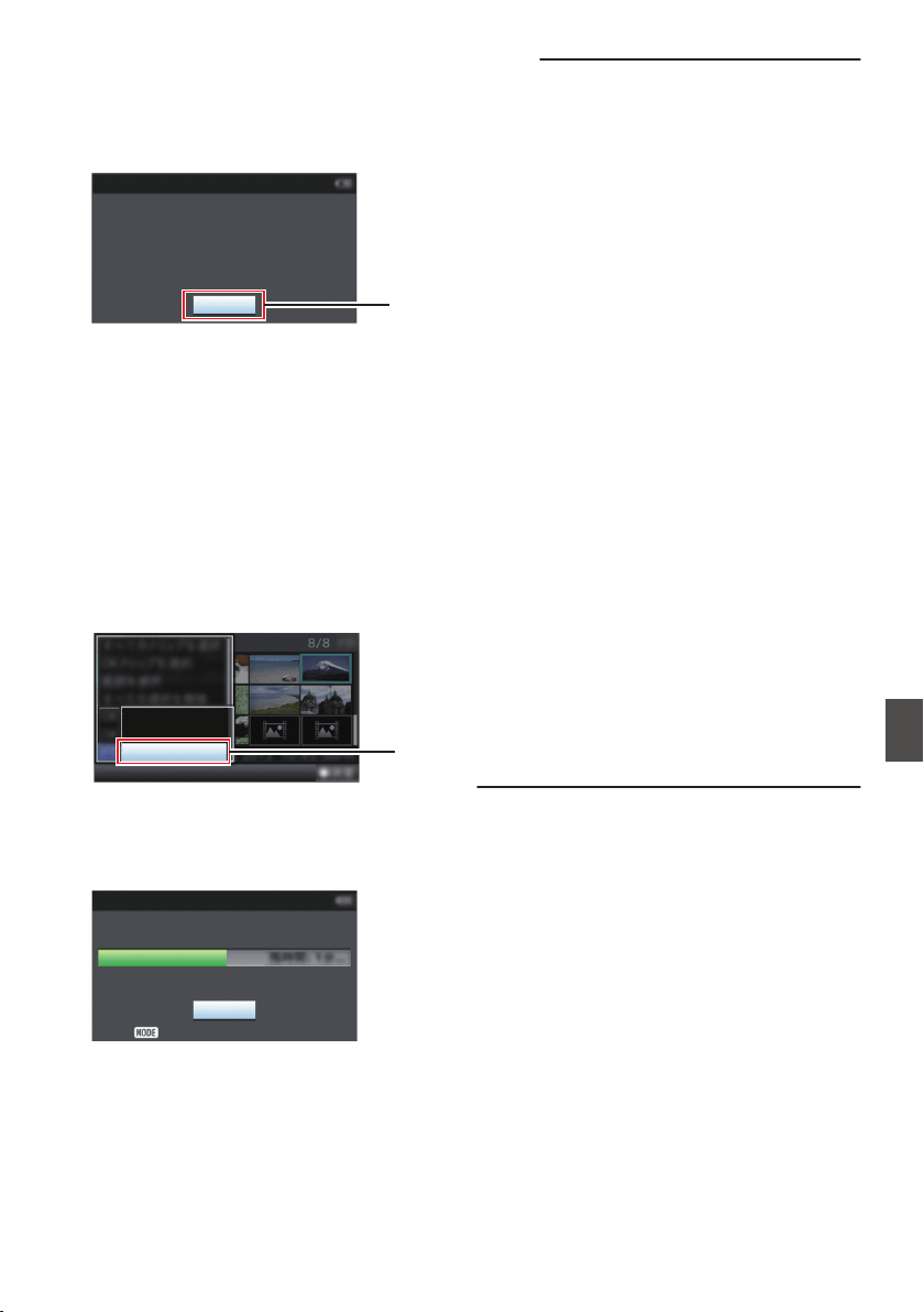
5
Upload is complete.
0
After upload is complete, “Successfully
Completed.” appears on the screen.
0
Press the Set button (R) to return to the
thumbnail screen.
.
5
Exit
Successfully Completed.
FTP Upload
Selecting and Uploading Multiple Clips
To select and upload multiple clips, refer to
“[Selecting and Performing Operations on Multiple
Clips] P 100”.
Uploading All Video Clips
1
Press the [LOAD FILE/3] button.
The action selection screen is displayed.
2
Upload the clips.
Select [FTP Upload...] B [All Clips] B server to
upload to, and press the Set button (R).
.
All Clips
Selected Clips
This Clip
2
3
Upload starts.
The status of the transfer process is indicated
by a progress bar.
.
Upload in Background
Stop
FTP Upload
Memo :
0
To stop uploading, press the Set button (R).
Select [Yes] on the confirmation screen, and
press the Set button (R) to stop uploading and
return to the thumbnail screen.
0
If there already exists a file on the FTP server
with a name identical to the file to be transferred,
a confirmation screen asking to overwrite the file
will appear.
However, if “HTTP” is selected in the [Select
FTP Proxy] screen of the network connection
settings, an overwrite confirmation screen does
not appear, and the existing file will be
overwritten directly.
0
Even after uploading has started in step 3 (FTP
transfer in progress), you can press the [CAM/
MEDIA] selection button to perform shooting in
the Camera mode.
0
If a setting other than “FTP” is specified for
[Protocol], to ensure the safety of the
communication path, a screen appears
prompting you to validate the fingerprint of the
public key and certificate received from the
server.
Check to ensure that the displayed value
coincides with the known value.
0
Fingerprint is a unique value that varies with
each public key and certificate.
0
For details of the fingerprint, please consult
the administrator of the server to be
connected.
(A P140 [ Clip Server ] )
0
When “HTTP” is selected in the [Select FTP
Proxy] screen of the network connection setting,
connections to the servers other than “FTP”
protocol cannot be made.
Uploading a Recorded Video Clip
181
Connecting to the Network
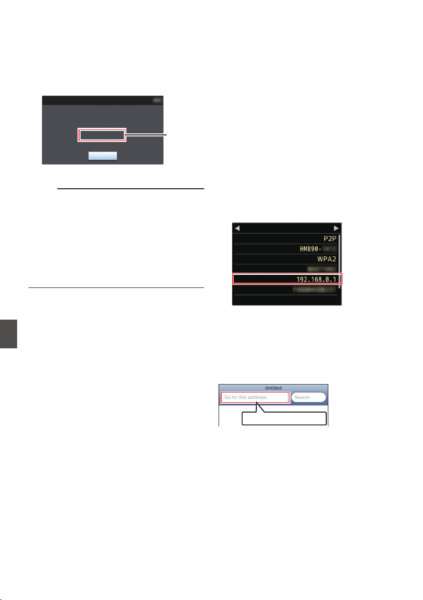
4
Upload is complete.
0
After all clips are uploaded successfully,
“Successfully Completed.” is displayed.
Press the Set button (R) to return to the
thumbnail screen.
0
When clips are not uploaded successfully,
the following errors are displayed.
.
Cause of
Error
Exit
Internal Error.
Failed.
FTP Upload
(A P203 [List of FTP Transfer Errors] )
Memo :
0
If a notification such as a an error message
appears after shifting to the Camera mode while
FTP transfer is in progress, a 5 icon (yellow) will
appear in the media’s remaining level display
area in the Camera mode.
When the [CAM/MEDIA] selection button is
pressed and held down to switch to the Media
mode, the above error screen appears.
Follow “[List of FTP Transfer Errors] P 203” to
clear the error message.
Connecting from a Web
Browser
You can access the web functions of this camera
recorder via a web browser on devices such as a
smartphone, tablet terminal, or PC.
Make the necessary preparations for connection in
advance.
(A P175 [Connect an appropriate adapter
according to the intended use to the [HOST]
terminal at the rear of the camera recorder.] )
1
Set the camera recorder to the Camera
mode, and display the [Network] (status)
screen.
0
Press the [STATUS] button on the camera
recorder to display the status screen.
Press the cross-shaped button (HI) to
display the [Network] screen.
0
Check the displayed [IP Address].
.
SSID
Live Streaming
MAC Address
IP Address
Passphrase
Security Type
Ty p e
Network
2
Start up the web browser on the terminal
you wish to connect to the camera
recorder, and enter the [IP Address] in the
address field.
If “192.168.0.1” is displayed in [IP Address],
enter “http://192.168.0.1”.
.
http://192.168.0.1
182
Uploading a Recorded Video Clip
Connecting to the Network
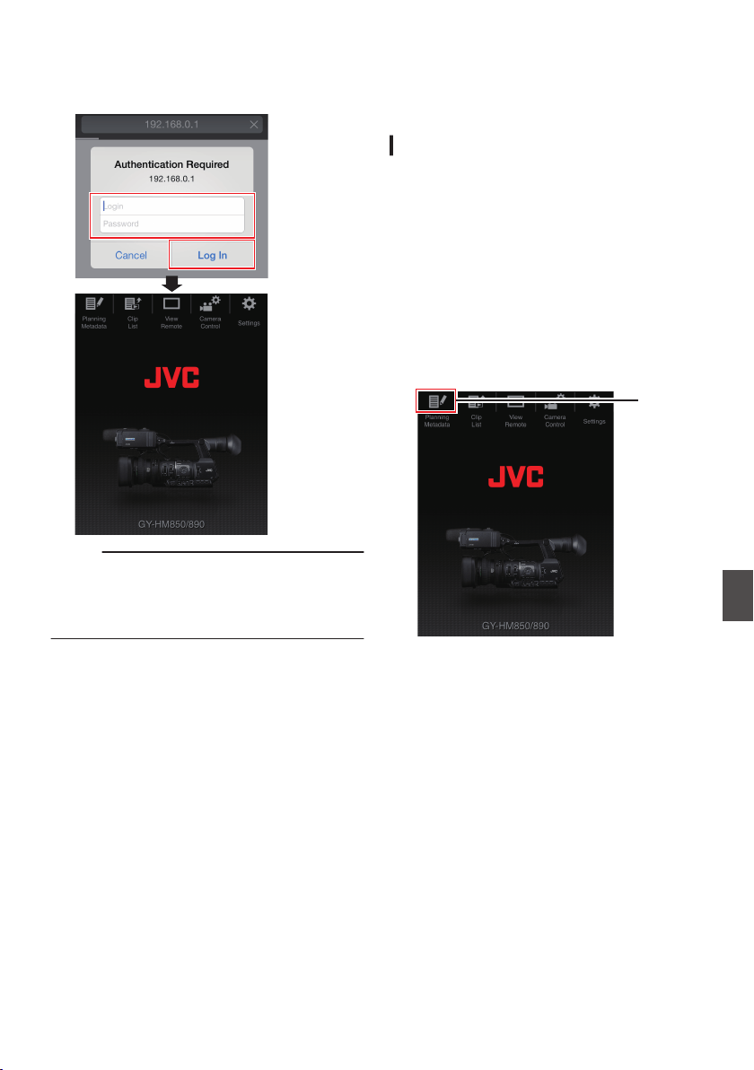
3
Enter the user name and password.
Enter the user name (prohd) and the password
(initial password: 0000) on the login screen to
display the main page of the camera.
.
Memo :
0
The password can be altered in [Main Menu] B
[System] B [Network]/[Settings] B [Web] B
[Login Password].
(A P137 [ Login Password ] )
Editing Metadata
You can create the metadata to be inserted into a
recorded file, or rewrite the metadata of a recorded
clip.
Planning Metadata
You can access the page for editing the camera
recorder’s metadata via a web browser on devices
such as a smartphone, tablet terminal, or PC, and
edit the metadata that is to be applied to clips to be
recorded.
1
Access the main page of the camera.
Access the page via a web browser on devices
such as a smartphone, tablet terminal, or PC.
(A P182 [Connecting from a Web Browser] )
2
Display the Planning Metadata screen.
Tap (click) the [Planning Metadata] tab to open
the [Planning Metadata] screen.
.
2
Connecting from a Web Browser
183
Connecting to the Network
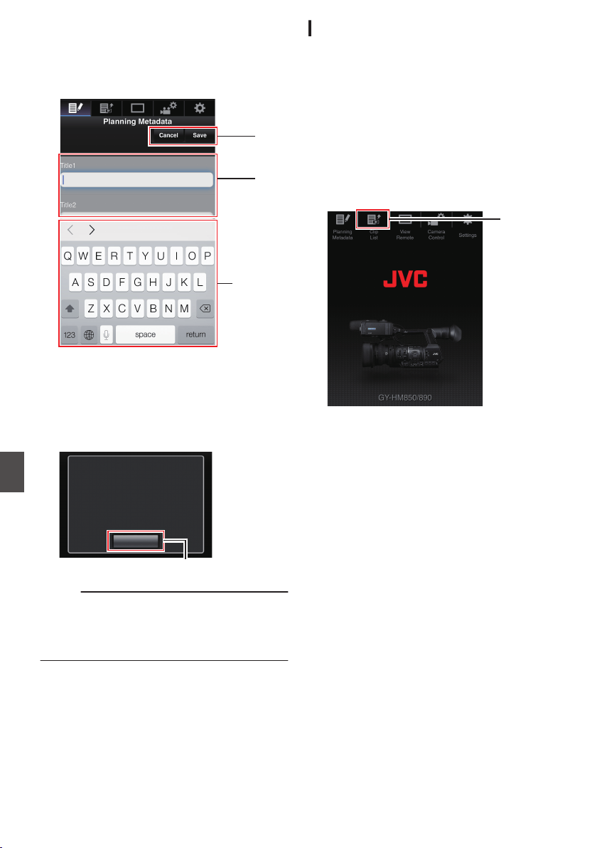
3
Editing Metadata
A
Enter information for the necessary fields.
B
After input is complete, tap (click) [Save] to
overwrite the metadata.
.
A
B
Keyboard
Done
4
Tap (click) [OK] on the confirmation screen.
0
Update of the [Planning Metadata] starts.
0
After update is complete, “Renewal of
planning metadata is succeeded.” is
displayed. Tap (click) [OK].
0
Returns to the screen in step 3.
.
4
OK
Renewal of planning metadata is
succeeded.
Memo :
0
If update failed, “Renewal of planning metadata
is failed.” is displayed.
Tap (click) [Close] to return to the screen of step
3.
Clip Metadata
You can access the page for editing the metadata
via a web browser on devices such as a
smartphone, tablet terminal, or PC, and display or
rewrite the metadata that is recorded to a clip.
1
Access the main page of the camera.
Access the page via a web browser on devices
such as a smartphone, tablet terminal, or PC.
(A P182 [Connecting from a Web Browser] )
2
Display the clip list.
Tap (click) the [Clip List] tab to display the clip
list.
.
2
3
Set the camera recorder to the “Remote
Edit Mode”.
You can switch to “Remote Edit Mode” from a
web browser or through operation of the
camera.
184
Editing Metadata
Connecting to the Network
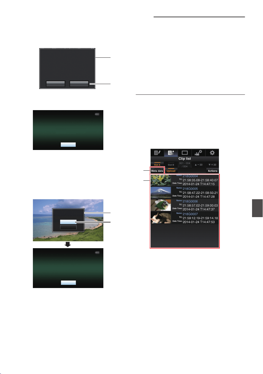
o Switching from a web browser
A
You will see a message indicating “It is
necessary to change the camera mode to
"Remote Edit Mode". Change the mode.” on
the web browser.
.
A
B
ChangeCancel
It is necessary to change the camera
mode to "Remote Edit Mode".
Change the mode.
B
Tap (click) [Change] to switch the camera to
the Remote Edit mode.
.
Exit
Remote Edit Mode
o Switching from the camera
A
“Change to Remote Edit Mode?” is
displayed on the display screen of the
camera unit.
B
Select [Change] and press the Set button
(R) to switch to the Remote Edit mode.
.
B
A
Exit
Remote Edit Mode
Cancel
Change
Remote Edit Mode?
Change to
Memo :
0
When the menu or status is displayed, display
of the confirmation screen will be put on hold.
0
If the menu is displayed on the camera recorder,
close the menu.
0
If the status is displayed on the camera recorder,
close the status display.
0
Pressing the Set button (R) on the camera
recorder while in the Remote Edit Mode ends
the Remote Edit Mode forcibly and switches to
the Camera mode.
0
When FTP upload via the camera unit is
currently in progress, switching to the Remote
Edit mode is disabled.
4
Select the Metadata Edit mode.
Select the [Metadata] tab.
5
Select the clip for which you want to rewrite
the metadata.
0
A list of the recorded clips appears on the
[Clip List] screen.
0
Tap (click) the clip for which you want to
rewrite the metadata.
.
4
5
Editing Metadata
185
Connecting to the Network
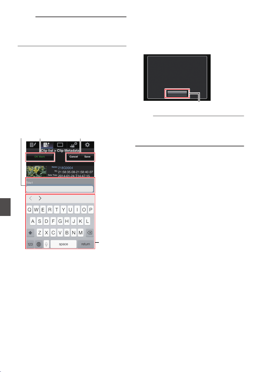
Memo :
0
You can switch the displayed slot using the [Slot
A] and [Slot B] tabs.
0
You can use the [J-30] or [K+30] tab to jump to
the previous or next 30 clips on the list.
6
Editing the Metadata of Selected Clips
A
Edit the information for the necessary fields.
0
If you are using a PC, input using the mouse
and keyboard.
0
If you are using a smartphone or tablet
terminal, tap the text input area to display a
standard software keyboard on the screen.
Enter the information using the displayed
keyboard.
B
You can tap (click) [OK Mark] to add an OK mark
to or delete it from selected clips.
C
After editing is complete, tap (click) [Save] to
overwrite the metadata.
.
BA C
Keyboard
Done
7
Tap (click) [OK] on the confirmation screen.
0
Update of the metadata starts.
0
After update is complete, “Renewal of clip
metadata is succeeded.” is displayed. Tap
(click) [OK].
0
Returns to the screen in step 4.
.
7
OK
Renewal of clip metadata is
succeeded.
Memo :
0
If update failed, “Renewal of clip metadata is
failed.” is displayed.
Tap (click) [Close] to return to the screen of step
4.
186
Editing Metadata
Connecting to the Network
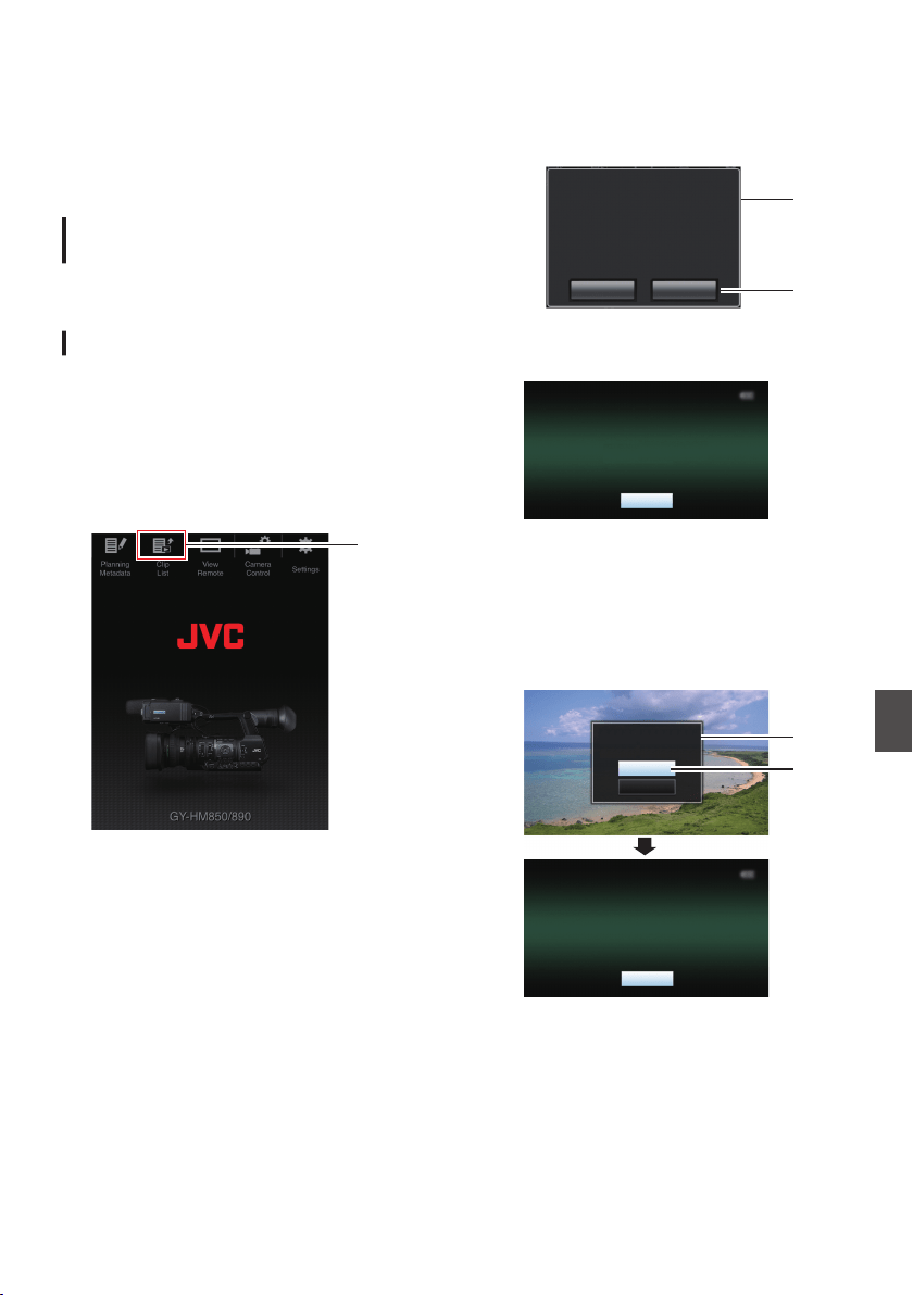
Uploading a Recording
Clip via a Web Browser
0
Upload clips recorded in the SD card to a preset
FTP server.
0
You can upload selected clips, all clips, or those
appended with an OK mark.
Configuring the FTP Server for
Uploading
(A P180 [Configuring the FTP Server for
Uploading] )
Uploading Video Clips
1
Access the main page of the camera.
Access the page via a web browser on devices
such as a smartphone, tablet terminal, or PC.
(A P182 [Connecting from a Web Browser] )
2
Display the clip list.
Tap (click) the [Clip List] tab to display the clip
list.
.
2
3
Set the camera recorder to the “Remote
Edit Mode”.
You can switch to “Remote Edit Mode” from a
web browser or through operation of the
camera.
o Switching from a web browser
A
You will see a message indicating “It is
necessary to change the camera mode to
"Remote Edit Mode". Change the mode.” on
the web browser.
.
A
B
ChangeCancel
It is necessary to change the camera
mode to "Remote Edit Mode".
Change the mode.
B
Tap (click) [Change] to switch the camera to
the Remote Edit mode.
.
Exit
Remote Edit Mode
o Switching from the camera
A
“Change to Remote Edit Mode?” is
displayed on the display screen of the
camera unit.
B
Select [Change] and press the Set button
(R) to switch to the Remote Edit mode.
.
B
A
Exit
Remote Edit Mode
Cancel
Change
Remote Edit Mode?
Change to
Uploading a Recording Clip via a Web Browser
187
Connecting to the Network
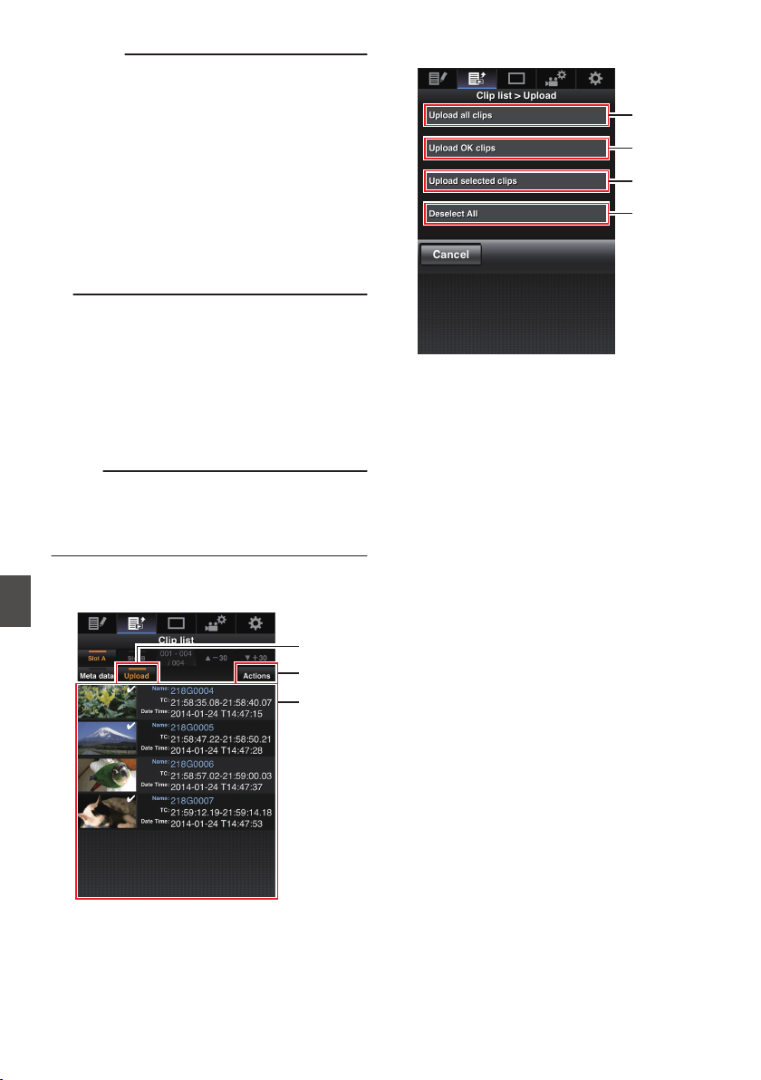
Memo :
0
When the menu or status is displayed,
display of the confirmation screen will be
put on hold.
0
If the menu is displayed on the camera
recorder, close the menu.
0
If the status is displayed on the camera
recorder, close the status display.
0
Pressing the Set button (R) on the camera
recorder while in the Remote Edit Mode
ends the Remote Edit Mode forcibly and
switches to the Camera mode.
0
When FTP upload via the camera unit is
currently in progress, switching to the
Remote Edit mode is disabled.
4
Select the Upload mode.
Select the [Upload] tab.
5
Select the clip you want to upload.
0
A list of the recorded clips appears on the
[Clip List] screen.
0
Tap (click) the clip you want to upload to
select it.
0
Clips being selected are indicated by a
check mark.
Memo :
0
You can switch the displayed slot using the [Slot
A] and [Slot B] tabs.
0
You can use the [J-30] or [K+30] tab to jump to
the previous or next 30 clips on the list.
6
Select the upload operation.
Tap (click) the [Actions] button.
.
4
6
5
7
Select a method to upload the clips.
.
A
B
C
D
A
Upload all clips
Uploads all the clips in the displayed slots.
Tap (click) to move to the [Clip Server] screen.
B
Upload OK clips
Uploads all clips in the displayed slots that are
appended with an OK mark.
Tap (click) to move to the [Clip Server] screen.
C
Upload selected clips
Uploads the clips you have selected.
Tap (click) to move to the [Clip Server] screen.
D
Clear all selection
Clears all clip selection and returns to the [Clip
List] screen.
188
Uploading a Recording Clip via a Web Browser
Connecting to the Network
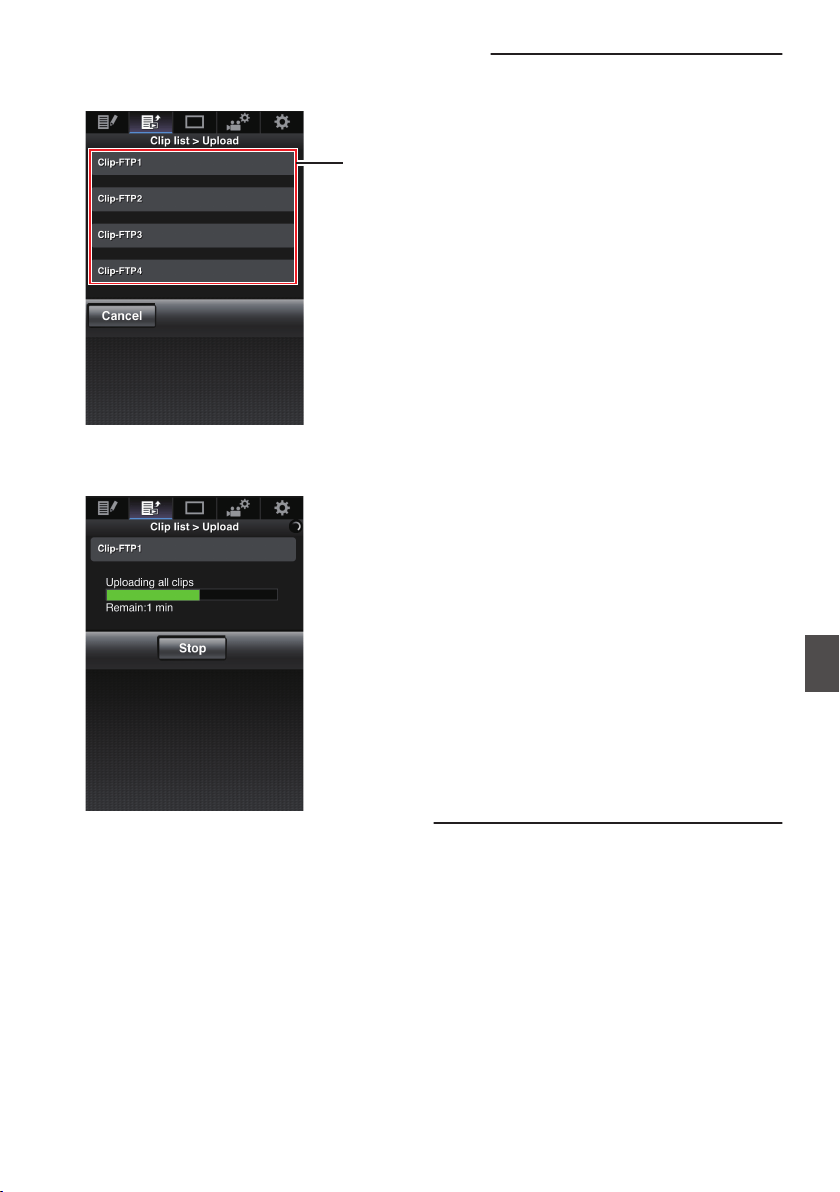
8
Select the clip server and start uploading.
0
Upon selecting the server to upoload clips to,
an upload screen appears.
.
8
0
The status of the transfer process is
indicated by a progress bar.
.
Memo :
0
To stop transfer, tap (click) the [Stop] button.
Tapping (clicking) [Yes] on the confirmation
screen stops the transfer halfway and brings you
back to the main page.
0
If there already exists a file on the FTP server
with a name identical to the file to be transferred,
a confirmation screen asking to overwrite the file
will appear.
However, if “HTTP” is selected in the [Select
FTP Proxy] screen of the network connection
settings, an overwrite confirmation screen does
not appear, and the existing file will be
overwritten directly.
0
After uploading in step 8 has started, other web
browser operations are disabled until uploading
is complete.
0
After uploading in step 8 has started and upon
shifting to the Media mode by pressing the
[CAM/MEDIA] selection button, operation from
the web browser will be disabled.
To enable web browser operation, press the
[CAM/MEDIA] selection button again to switch
to the Camera mode.
0
If a setting other than “FTP” is specified for
[Protocol], to ensure the safety of the
communication path, a screen appears
prompting you to validate the fingerprint of the
public key and certificate received from the
server.
Check to ensure that the displayed value
coincides with the known value.
0
Fingerprint is a unique value that varies with
each public key and certificate.
0
For details of the fingerprint, please consult
the administrator of the server to be
connected.
(A P140 [ Clip Server ] )
0
When “HTTP” is selected in the [Select FTP
Proxy] screen of the network connection setting,
connections to the servers other than “FTP”
protocol cannot be made.
Uploading a Recording Clip via a Web Browser
189
Connecting to the Network
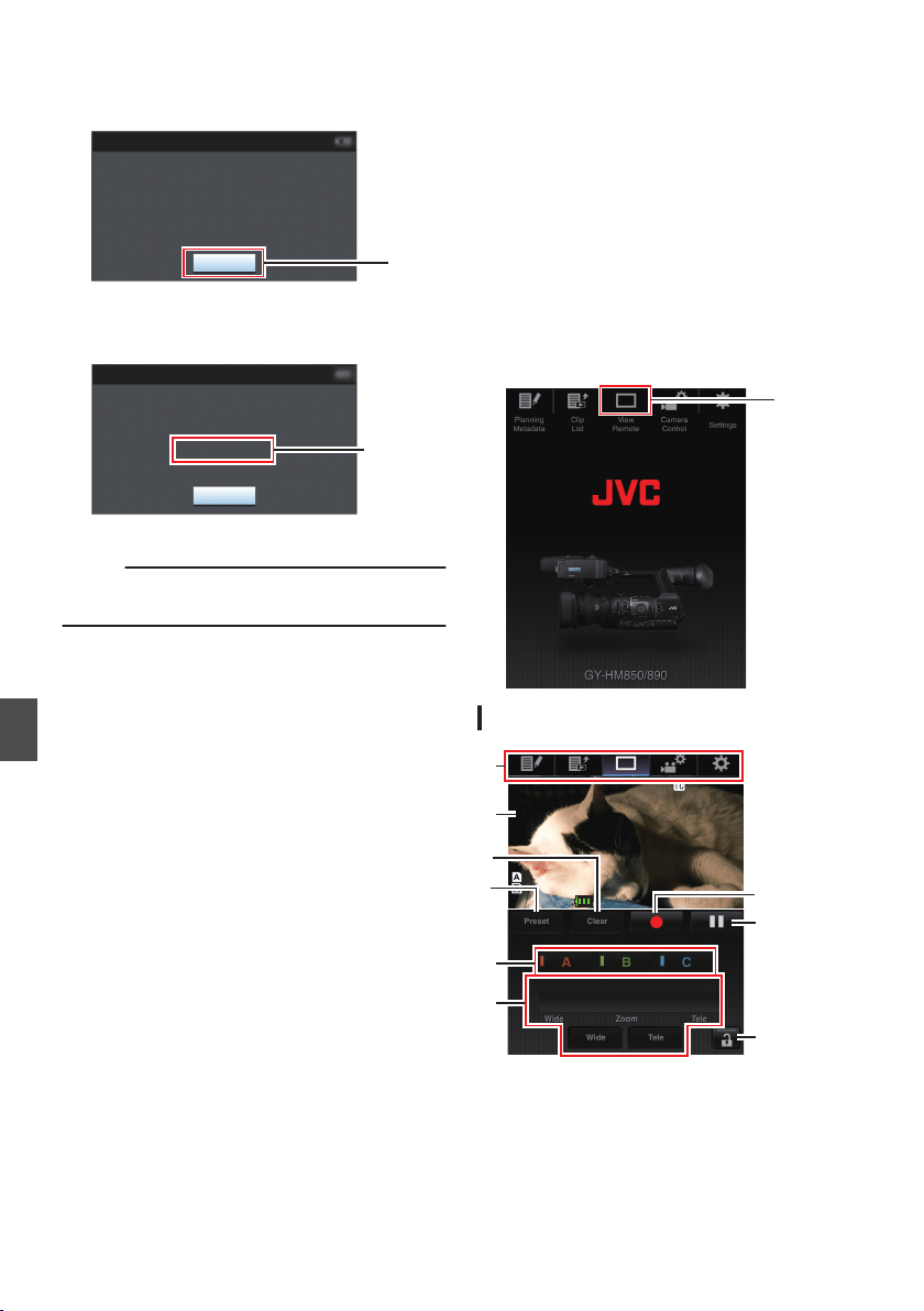
9
Upload is complete.
0
After upload is complete, “Complete”
appears on the screen.
.
9
Exit
Successfully Completed.
FTP Upload
0
When clips are not uploaded successfully,
the following errors are displayed.
.
Cause of
Error
Exit
Internal Error.
Failed.
FTP Upload
(A P203 [List of FTP Transfer Errors] )
Memo :
0
Follow “[List of FTP Transfer Errors] P 203” to
clear the error message.
View Remote Feature
You can access via a web browser on devices such
as a smartphone, tablet terminal, or PC to check
the live image and perform the following remote
control operations.
0
Start/stop recording
0
Zooming
0
Register/delete preset zoom
1
Access the main page of the camera.
Access the page via a web browser on devices
such as a smartphone, tablet terminal, or PC.
(A P182 [Connecting from a Web Browser] )
2
Tap (click) the [View Remote] tab to open
the [View Remote] screen.
.
2
Operating Procedure
.
26min
26min
50min
50min
01:
12
12:
54
54.
19
19
STBY
STBY
282min
282min
ProHD
ProHD
Z 00
Z 00
A
B
G
H
I
D
E
C
F
190
Uploading a Recording Clip via a Web Browser
Connecting to the Network
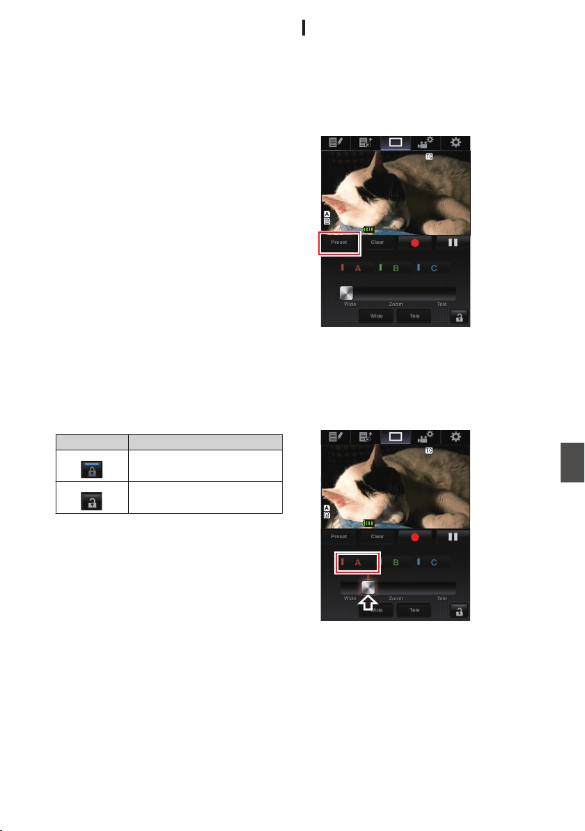
A
Page Switch Tab
Tap (click) to move to screen such as [Planning
Metadata], [Clip List], [Settings].
B
Live View Screen
Displays the live images.
Tap a live image to display or hide information
that is displayed on the live image, such as
remaining space on the media and time code.
C
[Clear] Button
Switches to the Delete Preset Zoom Position
mode.
(A P191 [Registering/Deleting Preset Zoom] )
(A P192 [Deleting a Preset Zoom] )
D
[Preset] Button
Switches to the Register Preset Zoom Position
mode.
(A P191 [Registering Preset Zoom] )
E
[A]/[B]/[C] Buttons
Use these buttons to perform preset registration
or delete a preset data.
F
Zoom Control
0
Operate the zoom function by dragging the
zoom button along the sliding bar.
0
Tap (click) the [Wide] or [Tele] button to fine-
tune the zoom position.
G
Function Lock Button
Locks the functions that have been set on the
[Settings] screen.
(A P195 [Changing View Remote Function
Settings] )
Icon Description
.
Locked
.
Not locked
H
Stop Record Button
I
Start Record Button
Registering/Deleting Preset Zoom
Registering Preset Zoom
You can register any 3 zoom positions.
1
Set to the Register Preset Zoom mode.
Tap (click) the [Preset] button to switch to the
Register Preset Zoom mode.
.
26min
26min
50min
50min
01:
12
12:
54
54.
19
19
STBY
STBY
282min
282min
ProHD
ProHD
Z 00
Z 00
2
Determine the zoom position.
Use the zoom control to operate the zoom and
determine a position.
3
Tap (click) [A].
Position [A] is registered, and position A is
displayed on the sliding bar of the zoom control.
.
26min
26min
50min
50min
01:
12
12:
54
54.
19
19
STBY
STBY
282min
282min
ProHD
ProHD
Z 00
Z 00
View Remote Feature
191
Connecting to the Network
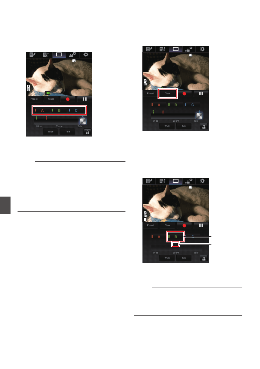
4
In the same way, register [B] and [C].
After all three positions A, B and C are
registered, the positions of the [A], [B], and [C]
buttons will be rearranged according to the
order of the registered zoom position from the
left.
.
26min
26min
50min
50min
01:
12
12:
54
54.
19
19
STBY
STBY
282min
282min
ProHD
ProHD
Z 00
Z 00
5
Exit the Register Preset Zoom mode.
Tap (click) the [Preset] button to exit the
Register Preset Zoom mode.
Memo :
0
After registration is complete ([A], [B], and [C]
buttons are all active), tapping (clicking) each
button switches to the corresponding preset
zoom position.
0
This function operates independently of the
preset zoom position on the camera recorder.
(A P52 [Saving/Recalling Current Zoom
Position (Preset Zoom) F] )
Deleting a Preset Zoom
1
Set to the Delete Preset Zoom mode.
When any of positions [A], [B], and [C] are
registered, tapping (clicking) the [Clear] button
switches to the Delete Preset Zoom mode.
.
26min
26min
50min
50min
01:
12
12:
54
54.
19
19
STBY
STBY
282min
282min
ProHD
ProHD
Z 00
Z 00
2
Tap (click) the [A], [B], or [C] button that
corresponds to the position you want to
delete.
0
The position is deleted, and the button is
grayed out.
0
The corresponding zoom position mark on
the sliding bar also disappears.
.
----min
----min
----min
----min
----
----
15
15
:5
:51:
17
17.
23
23
HM890
HM890
G
Position mark
disappears
Grayed out
3
Exit the Delete Preset Zoom mode.
Tap (click) the [Clear] button to exit the Delete
Preset Zoom mode.
Memo :
0
The Clip Review function of the camera recorder
is unavailable during View Remote operation.
(A P83 [Viewing Recorded Videos Immediately
(Clip Review)] )
192
View Remote Feature
Connecting to the Network
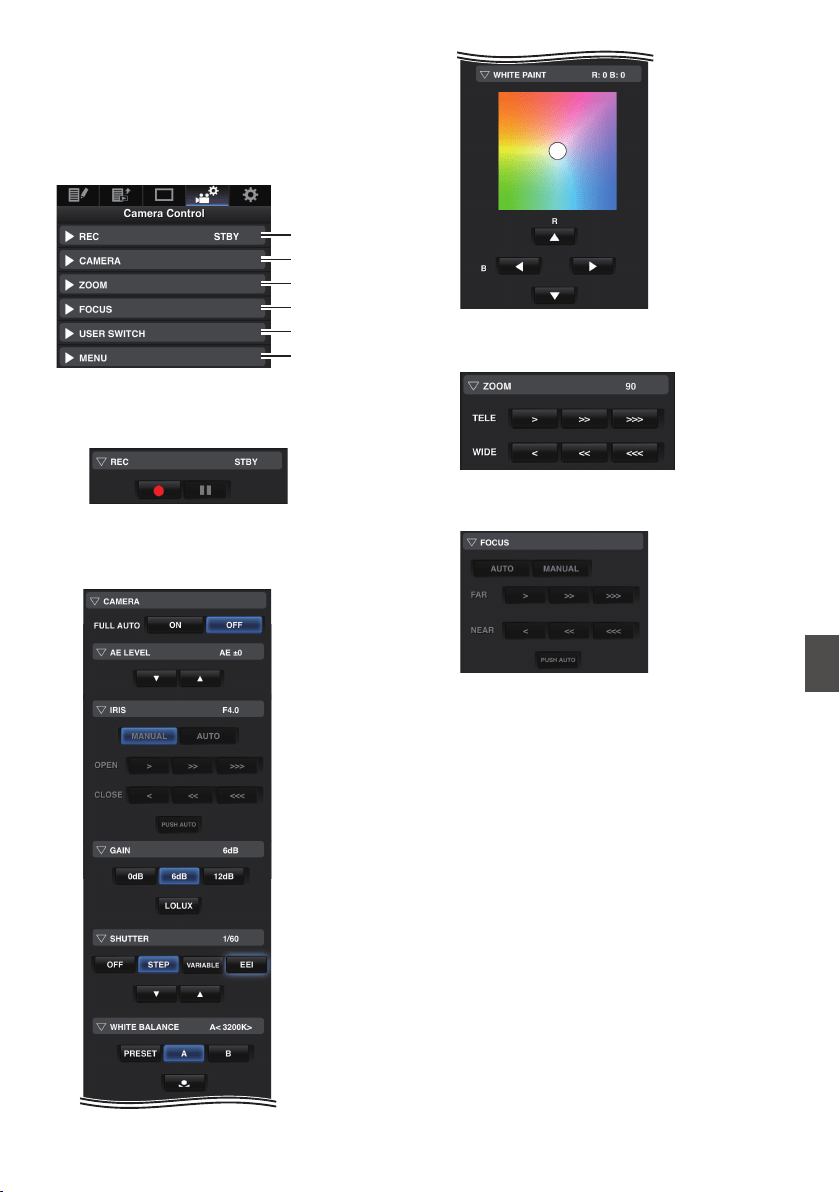
Camera Control Function
You can control the camera by accessing via a web
browser on devices such as a smartphone, tablet
terminal, or PC.
You can perform the following operations for each
of the items.
.
A
B
C
D
E
F
HM890
HM890
A
REC
For performing recording start or recording
pause operation.
.
B
CAMERA
Enables operations related to the camera
functions.
.
.
C
ZOOM
Enables zooming operations.
.
D
FOCUS
Enables focusing operations.
.
Camera Control Function
193
Connecting to the Network
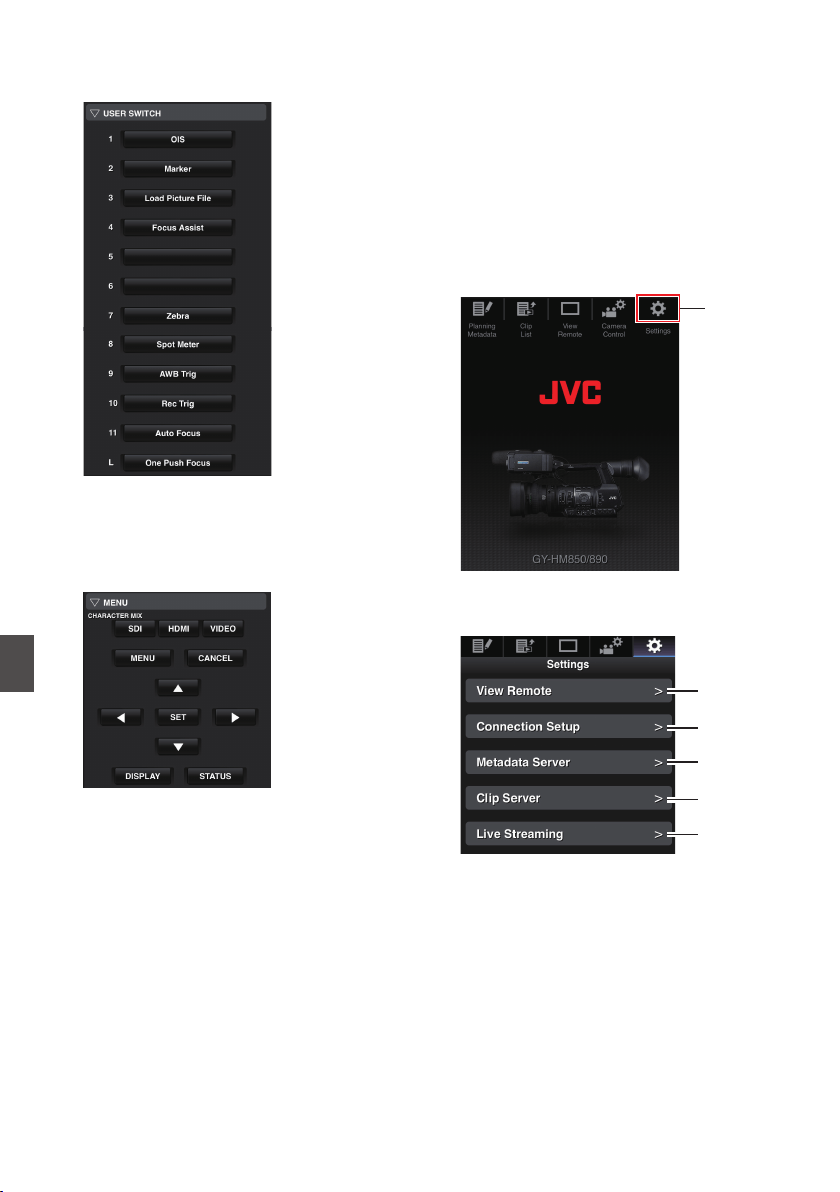
E
USER SWITCH
You can enable or disable the user buttons that
are assigned with a function.
.
F
MENU
You can show or hide the display and menu
characters on an external monitor as well as
operation of menus, switching the display
screen and status display.
.
Changing the Settings via
a Web Browser
You can change the network-related settings by
accessing via a web browser on devices such as a
smartphone, tablet terminal, or PC.
1
Access the main page of the camera.
Access the page via a web browser on devices
such as a smartphone, tablet terminal, or PC.
(A P182 [Connecting from a Web Browser] )
2
Tap (click) the [Settings] tab.
.
2
3
The [Settings] screen appears.
Set each of the items as follows.
.
A
B
C
D
E
194
Camera Control Function
Connecting to the Network

A
View Remote
Settings for operations on the View Remote.
B
Connection Setup
Settings related to the network.
You can change the settings for each of the
preset items on the [Wizard] screen of the
camera recorder.
C
Metadata Server
Settings on the server for importing the
metadata.
Setting can be performed in the same way as
the [Metadata Server] menu on the camera
recorder.
The latest settings are reflected, regardless of
whether they are specified via the camera
recorder or web operation.
D
Clip Server
Settings for the server to upload recorded clips
to.
Setting can be performed in the same way as
the [Clip Server] menu on the camera recorder.
The latest settings are reflected, regardless of
whether they are specified via the camera
recorder or web operation.
E
Live Streaming
Setting for streaming audio and video via the
network.
The latest settings are reflected, regardless of
whether they are specified via the camera
recorder or web operation.
Memo :
0
Priority is given to menu operation on the
camera recorder.
0
When the menu on the camera recorder is
opened while the [Settings] screen is opened
using a web browser, a warning appears, after
which the display returns to the main screen.
0
While the menu is displayed on the camera
recorder, the [Settings] screen cannot be
opened via the web browser.
Changing View Remote Function
Settings
For performing setting for using the View Remote
function.
.
A
B
C
A
[Camera Name]
0
For setting the name that appears at the top
left of the view screen.
0
Tapping the text input area displays a
software keyboard.
If you are using a PC, enter using the PC
keyboard.
0
By tapping the Go key after input is complete,
the software keyboard disappears.
B
[Restrictions]
For setting the buttons to be disabled on the
View screen while in the locked mode.
0
[REC]:
For setting whether to disable the Stop
Record button or zoom operation during
recording.
Tap (click) each item to switch between
[Unlock] and [Lock].
0
[Except REC]:
For setting whether to disable the Record
button or zoom operation in any operation
other than during recording.
Tap (click) each item to switch between
[Unlock] and [Lock].
C
[Save]/[Cancel]
Tap (click) [Save] to save the settings.
Tap (click) [Cancel] to stop setting and return to
the main [Settings] screen.
Changing the Settings via a Web Browser
195
Connecting to the Network
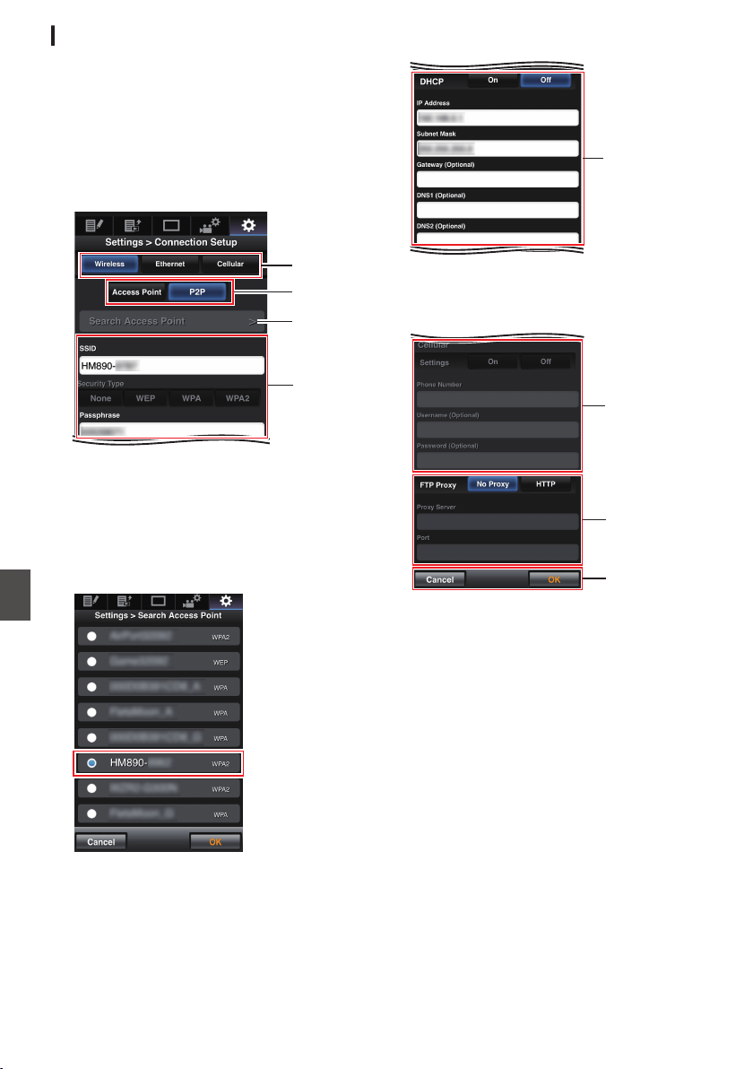
Changing Connection Setup
You can change the settings for each of the preset
items on the [Wizard] screen of the camera
recorder.
0
If all the items cannot be displayed in a single
page, scroll down to display the remaining
items.
0
Items that cannot be changed are grayed out
according to the type of adapter connected and
the mode of connection.
.
A
D
C
B
A
Type of Adapter Connected
B
Mode of Wireless LAN Connection
C
[Search Access Point] Button
Tap (click) to display a list of the detected
access points.
The currently selected access point is indicated
by a dot mark ( 0 ).
.
D
Settings during the use of wireless LAN
.
E
E
IP address settings
When “DHCP” is selected, all items will be
grayed out.
.
F
G
H
F
Settings when using a cellular adapter
G
Proxy settings when using FTP
H
[OK]/[Cancel] Button
After changing of settings is complete, tap
(click) the [OK] button.
On the confirmation screen, tap (click)
[Execute] to change the settings on the camera
recorder and restart the network.
196
Changing the Settings via a Web Browser
Connecting to the Network
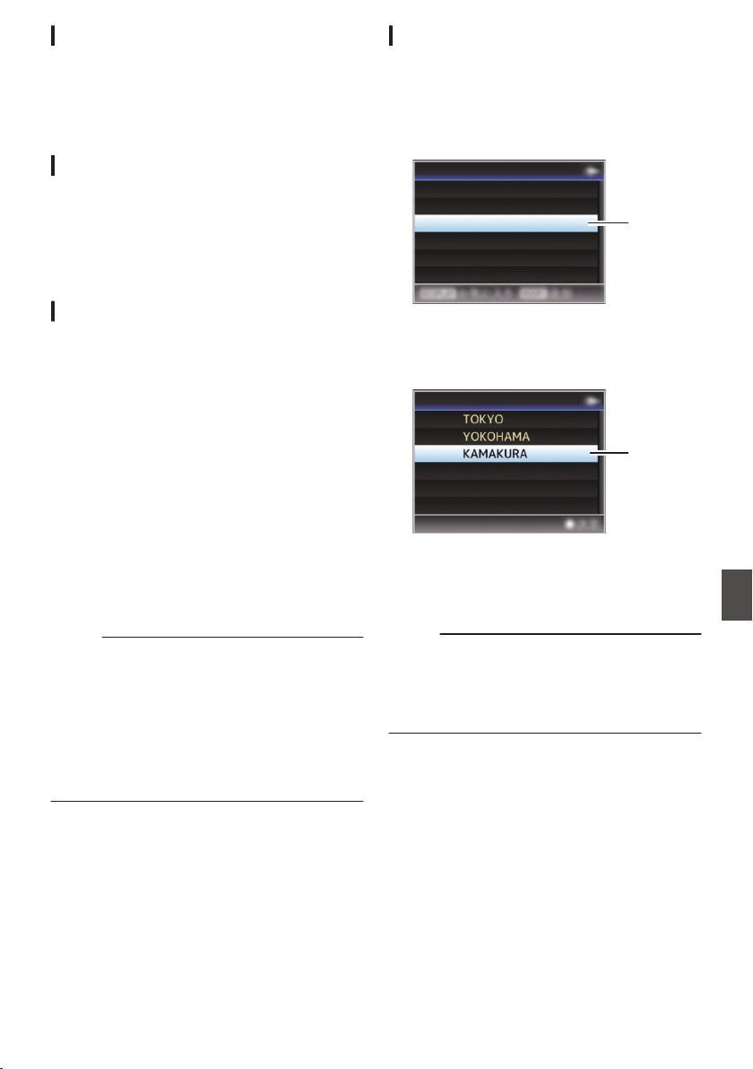
Changing Metadata Server Settings
You can make direct changes to the FTP server for
importing the metadata set in [Main Menu] B
[System] B [Network]/[Settings] B [Metadata
Server], as well as the path of the file to import.
(A P140 [ Metadata Server ] )
Changing Clip Server Settings
You can make direct changes to the server and
directory settings that are specified in [Main
Menu] B [System] B [Network]/[Settings] B [Clip
Server] for uploading recorded clips in the SD card
to the FTP server.
(A P140 [ Clip Server ] )
Changing Streaming Settings
You can make direct changes to settings that are
specified in [Main Menu] B [System] B [Network]/
[Settings] B [Live Streaming Set], such as
information on the destination of distribution.
(A P137 [ Live Streaming Set ] )
Managing the Network
Connection Settings File
This camera recorder allows you to save the
network connection settings on the Wizard screen
to the camera recorder unit.
Loading a saved connecting settings file enables
you to reproduce the appropriate network
connection state speedily.
Memo :
0
To save or load the connection settings, go to
[Main Menu] B [System] B [Network]/[Settings]
B [Connection Setup].
0
The following operations can be performed on
the [Connection Setup] menu.
0
[Saving the Connection Settings File] P 197
0
[Reading the Connection Settings
File] P 198
0
[Deleting Connection Settings] P 199
Number of Storable Setup Files
Camera recorder : [CAM1] to [CAM4]
Saving the Connection Settings File
1
Select [Main Menu]
B [System] B
[Network]/[Settings]
B [Connection Setup]
and press the Set button (
R).
2
Select [Store] and press the Set button (
R).
.
2
Delete
Store
Load
Wizard
Connection Setup
3
Select the file to be newly saved (or
overwritten) using the cross-shaped
button (
JK), and press the Set button (R).
.
3
<no file>
CAM4
CAM3
CAM2
CAM1
Store Connection Setup
4
Name the file.
Enter the subname using the software
keyboard.
(A P105 [Text Input with Software Keyboard] )
Memo :
0
When overwriting an existing file, the subname
of the existing file is displayed.
0
Select [Cancel] and press the Set button (R), or
press the [CANCEL] button to return to the
previous screen.
Changing the Settings via a Web Browser
197
Connecting to the Network
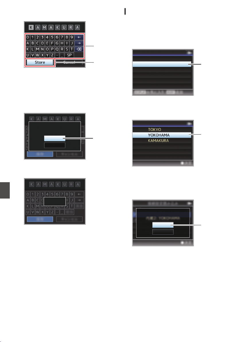
5
Select [Store] and press the Set button (
R).
.
5
4
6
Save the file.
0
A confirmation screen appears when you
choose to overwrite.
Select [Overwrite] on the confirmation
screen, and press the Set button (R). Saving
starts, and “Storing...” appears on the
screen.
.
:KAMAKURA
6
Cancel
Overwrite
CAM3
Setup?
Overwrite Connection
0
Saving starts, and “Storing...” appears on the
screen when the file is newly saved.
.
Storing...
7
Saving is complete.
After saving of the file is complete, “Complete”
appears on the screen, and the menu screen
closes automatically.
Reading the Connection Settings File
1
Select [Main Menu]
B [System] B
[Network]/[Settings]
B [Connection Setup]
and press the Set button (
R).
2
Select [Load] and press the Set button (
R).
.
2
Delete
Store
Load
Wizard
Connection Setup
3
Select the file to read using the cross-
shaped button (
JK), and press the Set
button (
R).
.
3
CAM3
CAM2
CAM1
Store Connection Setup
4
Select [Load] on the confirmation screen,
and press the Set button (
R).
Loading starts, and “Loading...” appears on the
screen.
.
:YOKOHAMA
4
Cancel
Load
CAM2
Setup?
Load Connection
5
Reading is complete.
After reading of the file is complete, “Complete”
appears on the screen, and the menu screen
closes automatically.
198
Managing the Network Connection Settings File
Connecting to the Network
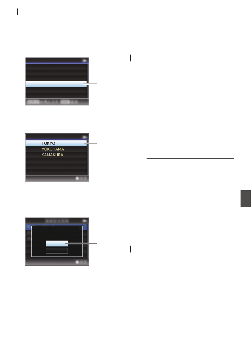
Deleting Connection Settings
1
Select [Main Menu]
B [System] B
[Network]/[Settings]
B [Connection Setup]
and press the Set button (
R).
2
Select [Delete] and press the Set button
(
R).
.
2
Delete
Store
Load
Wizard
Connection Setup
3
Select the file to delete using the cross-
shaped button (
JK), and press the Set
button (
R).
.
3
CAM3
CAM2
CAM1
Delete Connection Setup
4
Select [Delete] on the confirmation screen,
and press the Set button (
R).
Deletion starts, and “Deleting...” appears on the
screen.
.
:TOKYO
4
Cancel
Delete
CAM1
Setup?
Delete Connection
5
Deletion is complete.
After file deletion is complete, “Complete”
appears on the screen.
Performing Live
Streaming
By combining with a decoder device or PC
application that support live streaming, you can
perform audio and video streaming via the network.
Supported Formats
Video
H.264
0
1920x1080/60i (8.0 Mpbs), 60i (5.0 Mpbs),
60i (2.5 Mbps), 50i (8.0 Mpbs), 50i (5.0 Mpbs),
50i (2.5 Mbps)
0
1280x720/30p (5.0 Mpbs), 30p (3.0 Mpbs),
30p (1.5 Mbps), 25p (5.0 Mpbs),
25p (3.0 Mpbs), 25p (1.5 Mbps)
0
720x480/60i (5.0 Mpbs), 60i (3.0 Mpbs),
60i (1.5 Mbps), 60i (0.8 Mbps), 60i (0.3 Mbps),
60i (0.2 Mbps)
0
720x576/50i (5.0 Mpbs), 50i (3.0 Mpbs),
50i (1.5 Mbps), 50i (0.8 Mbps), 50i (0.3 Mbps),
50i (0.2 Mbps)
0
480x270/30p (0.2 Mbps), 25p (0.2 Mbps)
Memo :
0
The following constraints apply depending on
the setting of [Main Menu] B [System] B
[Network]/[Settings] B [Live Streaming Set] B
[Type].
0
An encoding bit rate exceeding 5.0 Mbps
cannot be selected in the case of “RTSP/
RTP”.
0
An encoding bit rate exceeding 3.0 Mbps
cannot be selected in the case of “ZIXI”.
(A P139 [ Type ] )
Audio
AAC
Supported Protocols
Network protocols : TCP, UDP
Transport mode : MPEG2-TS,
RTSP/RTP, ZIXI
Managing the Network Connection Settings File
199
Connecting to the Network
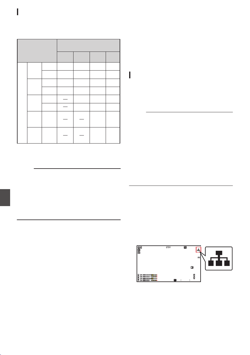
Setting Distribution
1
Set the [Record Format] according to the
resolution and frame rate of the video to be
distributed.
.
480x270
30p
25p
30p
30p
25p
720x
480
720x
576
30p
25p
25p
Record Format
Resolution/No. of Frames
1280x720
720x480
720x576
1920x
1080
60i,30p
60i
50i,25p
50i
1440x
1080
60i
60i
50i
1280x
720
60p,30p
60i
50p,25p
50i
60i
60i
50i
50i
1920x1080
50i
60i
50i
60i
50i
30p(*)
25p(*)
30p(*)
30p
25p
25p(*)
Settable Resolution during
Streaming/No. of Frames
* This item cannot be selected when [Main Menu]
B [System] B [Record Set] B [Record Format] B
[System] is set to “HD(SDI In)”.
Memo :
0
Live streaming cannot be performed in the
following cases.
0
When [Main Menu] B [System] B [Record
Set] B [Record Format] B [System] is set to
“HD+SD” or “HD+Web”
0
When [Main Menu] B [System] B [Record
Set] B [Record Format] B [WFrame & Bit
Rate] is set to “24p”
2
Set the Resolution and Frame & Bit Rate for
the video to be distributed.
Specify the settings in [Main Menu] B [System]
B [Network]/[Settings] B [Live Streaming Set].
(A P137 [ Live Streaming Set ] )
3
Set the distribution protocol.
Specify the settings in [Main Menu] B [System]
B [Network]/[Settings] B [Live Streaming Set]
B [Type].
(A P139 [ Type ] )
4
Set items related to the distribution
protocol.
Set each of the [Main Menu] B [System] B
[Network]/[Settings] B [Live Streaming Set] B
[UDP/TCP Settings]/[RTSP/RTP Settings]/
[ZIXI Settings] items.
(A P139 [ UDP/TCP Settings ] )
(A P139 [ RTSP/RTP Settings ] )
(A P139 [ ZIXI Settings ] )
Starting Distribution
1
Perform the necessary settings for the
decoder device or the PC application.
For details on the settings, please refer to the
instruction manual of the respective devices
and applications.
Memo :
0
If there is an NAT router within the
communication path between the camera and
the decoder, port forwarding setup is required.
For details on the settings, please refer to the
instruction manual of the router in use.
0
The following parameters are required when
connecting to this camera recorder using the
RTSP/RTP.
Port number: 554
Stream ID: stream
0
Use the following to access via URL.
rtsp://<IP address of the camera recorder>:554/
stream
2
With the network connection established,
set [Live Streaming] to “On”.
(A P174 [Preparing Network Connection] )
0
Set [Main Menu] B [System] B [Network]/
[Settings] B [Live Streaming Set] B [Live
Streaming] to “On”.
0
The network connection mark appears on
the display screen when a network
connection is established.
.
100min
50min
282min
P13000K
1/100
F1. 6
0
dB
AE+6
ND 1 /64
5 . 6 f t
12 :34 :56
Jan 24 , 2014
00: 00:00.00
1920x1080
60 i HQ
200
Performing Live Streaming
Connecting to the Network
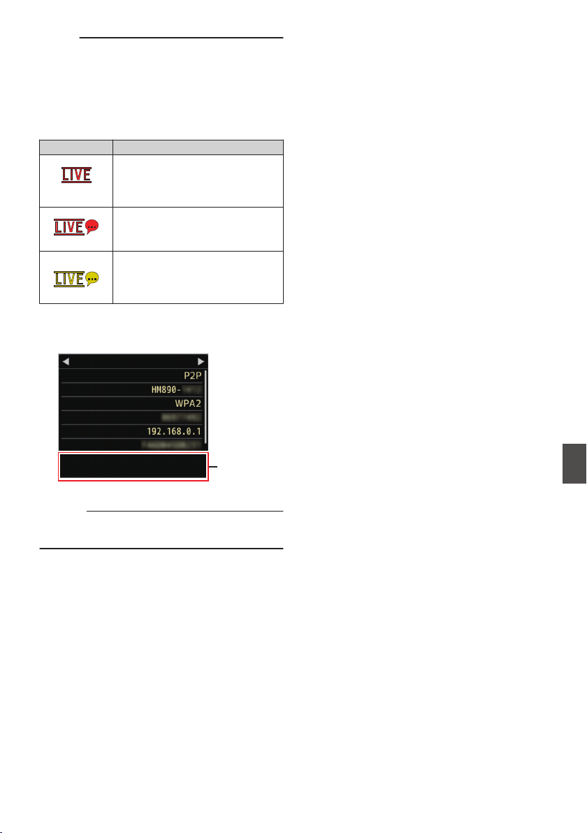
Memo :
0
You can also assign “Live Streaming” to a user
button.
(A P42 [Assignment of Functions to User
Buttons] )
0
You can view the status of distribution on the
LCD monitor.
(A P150 [Live streaming mark] )
Icon Status
.
(Red)
0
Distribution in progress (good
connection quality)
0
Blinks when distribution starts
or stops
.
(Red)
Distribution in progress (poor
connection quality)
.
(Yellow)
Waiting for connection (during
RTSP/RTP) or connection failed
0
When the 5 icon is displayed, you can view the
details of the error on the [Network] screen of the
status screen.
.
SSID
Cause of Error
Live Streaming
MAC Address
IP Address
Passphrase
Security Type
Ty p e
Network
Multicast Is Not Supported.
(A P205 [List of Live Streaming Error Displays] )
Caution :
0
Streaming may be interrupted temporarily 24
hours after the process started.
Performing Live Streaming
201
Connecting to the Network

Error Messages and Actions
Warning display on the LCD monitor and viewfinder screen, tally lamp indication and warning tone are as
follows according to the error status.
Memo :
0
This camera recorder makes use of a microcomputer. Noise interference from external sources may
prevent it from functioning properly. When this occurs, turn off and on the power of the camera recorder
again.
Error Message Status Action
Turn Power Off Turn Back On
Later
System error.
* The warning tone sounds and the
tally lamp blinks twice every
second.
Turn off the power, and turn it on
again.
If the error persists, please consult
your nearest service center.
Fan Stop Detected Please
Turn P.Off
The fan stopped running. Please consult your nearest service
center.
Fan Maintenance Required Usage time of the fan has exceeded
9000 hours.
Check the fan and replace
accordingly. For more details,
please consult your nearest service
center.
Memo :
0
You can check the usage time of
the fan in [System] B [System
Information] B [Fan Hour].
(A P132 [ Fan Hour ] )
Getting Overheated. Please
Turn Power Off.
0
The battery has exceeded the
specified temperature.
0
The power turns off
automatically after about 15
second.
0
Wait until the temperature drops
or replace the battery.
0
If the error persists, please
consult your nearest service
center.
Rec Inhibited [REC] button is pressed when the
write-protect switch of the SD card
is set.
Turn off the write-protect switch of
the SD card, or insert a recordable
SD card.
(A P43 [SD Card] )
Lost Media Info *
(*: A, B)
0
Card is removed while recording
is in progress.
0
Card is removed while
formatting is in progress.
0
Card is removed while restoring
is in progress.
0
Card is removed while adding
the OK mark.
0
Card is removed while writing a
setup file.
0
Card is removed while deleting a
clip.
Restore the card using this camera
recorder.
(A P46 [Restoring and Updating
the SD Card] )
202
Error Messages and Actions
Others
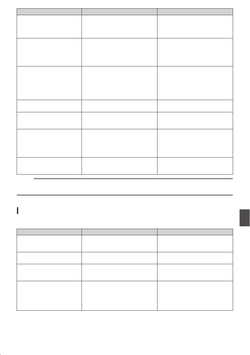
Error Message Status Action
Record Format Incorrect Video format of the file for Clip
Review is different from the current
[WResolution] and [WFrame & Bit
Rate] setting.
Set [WResolution] and [WFrame &
Bit Rate] correctly.
(A P133 [ W Resolution ] )
(A P133 [ W Frame & Bit Rate ] )
Media Full
0
[REC] button is pressed when
the media in use has no
remaining space.
0
Remaining space ran out during
recording.
Replace the SD card with a new
one.
No Clips No viewable clips are found on the
card for Clip Review.
Insert an SD card that contains clips
that can be reviewed.
(A P43 [SD Card] )
(A P83 [Viewing Recorded
Videos Immediately (Clip
Review)] )
No Media [REC] button is pressed when an SD
card is not inserted.
Insert an SD card.
(A P43 [SD Card] )
No Media No SD card is found in Media mode
or when the thumbnail screen is
displayed.
Insert an SD card.
(A P43 [SD Card] )
No Clips No clips are found on the inserted
SD card in Media mode or when the
thumbnail screen is displayed.
Insert an SD card that contains
playable clips.
(A P43 [SD Card] )
(A P94 [Playing Recorded
Clips] )
12h Continuation Record The continuous recording time in
AVCHD mode exceeds 12 hours
and recording stops automatically.
To continue recording, press the
[REC] button again.
Memo :
0
Please see below for error messages when auto white balance adjustment failed to complete.
(A P64 [Adjusting the White Balance] )
List of FTP Transfer Errors
If the upload of a recorded clip or download of the metadata setup file (XML format) is not successfully
completed, the following errors are displayed.
Error message Status Action
Timeout. Transfer was discontinued due to
timeout caused by network
transmission or server failure.
0
Execute again.
0
Use a different server.
Media Was Removed. SD card is removed while FTP
transfer is in progress.
Insert the SD card and execute FTP
transfer again.
Adapter Was Removed. The USB network adapter is
removed while FTP transfer is in
progress.
Connect the USB network adapter.
Cannot Connect to Server. Unable to connect to the FTP server. Adjust the Server and Port settings
for [Metadata Server] or [Clip
Server].
(A P140 [ Metadata Server ] )
(A P140 [ Clip Server ] )
Error Messages and Actions
203
Others

Error message Status Action
Access Denied. Access is denied. Adjust the Server and Port settings
for [Metadata Server] or [Clip
Server].
(A P140 [ Metadata Server ] )
(A P140 [ Clip Server ] )
Invalid Username or
Password.
Authentication for login to the FTP
server failed.
Adjust the Username and Password
settings for [Metadata Server] or
[Clip Server].
(A P140 [ Metadata Server ] )
(A P140 [ Clip Server ] )
Invalid Path Was Requested. The path specified for the FTP
server is incorrect.
Adjust the [Clip Server] and [Dir.
Path] settings for [Metadata
Server] or [File Path].
(A P140 [ Metadata Server ] )
(A P140 [ Clip Server ] )
Server Error. There was an unintended operation
of the FTP server.
Execute again.
Use a different server.
Invalid Request. A bad request is executed for the
FTP server.
Use a different server.
Invalid Data Size. Invalid data size, such as a planning
metadata size that exceeds 4 KB.
Adjust the planning metadata saved
in the Metadata Server.
(A P183 [ Planning Metadata ] )
Invalid Data Format. The XML format of the planning
metadata is invalid.
Adjust the planning metadata saved
in the Metadata Server.
(A P183 [ Planning Metadata ] )
Transfer Error. Transfer failed due to
communication failure.
Execute again.
Invalid URL. The path was deemed invalid by the
FTP server.
Adjust the Server and Port settings
for [Metadata Server] or [Clip
Server].
(A P140 [ Metadata Server ] )
(A P140 [ Clip Server ] )
Media Access Error. Reading/writing of the SD card
failed while FTP transfer is in
progress.
Insert a different SD card.
Internal Error. An internal error has occurred while
FTP transfer is in progress.
Adjust the settings and execute
again.
Other Error. An unknown error or other errors
have occurred while FTP transfer is
in progress.
Adjust the settings and execute
again.
Media Read Error. Reading of the SD card failed while
FTP transfer is in progress.
Insert a different SD card.
204
Error Messages and Actions
Others

List of Live Streaming Error Displays
The following error messages are displayed when the live streaming setting is incorrect, or when the
connection is lost during live streaming.
Error message Status Action
Invalid Address.
0
The IP address format is
incorrect.
0
The domain name cannot be
converted into the IP address.
0
Enter the IP address or host
name of the destination
correctly.
(A P200 [Setting Distribution] )
Multicast Is Not Supported. An IP multicast address was set. Use an IP address that is not a
multicast address.
Cannot Connect to Receiver. Establishment of connection with
TCP failed.
0
Ensure that the recipient’s
device is set to TCP.
0
Change the Type item to
“MPEG2-TS/UDP”.
(A P200 [Setting Distribution] )
TCP Disconnected. TCP connection is lost. Check to ensure that there is no
abnormality in the decoder, or
network connection device and
cables, followed by establishing the
connection again.
Not Enough Bandwidth.
0
The communication bandwidth
is narrower than the average bit
rate.
0
The network bandwidth is
insufficient, and packets are
discarded.
0
Lower the resolution/picture
quality of the video to be
distributed.
0
Consider switching to the use of
a stable network, such as wired
LAN.
Connection Timeout Timeout for connection via ZIXI. Set [Destination Address] and
[Destination Port] correctly.
(A P200 [Setting Distribution] )
Authorization Failed Authentication of connection via
ZIXI failed.
Set [Stream ID] and [Password]
correctly.
(A P200 [Setting Distribution] )
Connection Error Connection via ZIXI failed. Check whether a different camera
with an identical stream ID is
connected.
Disconnected ZIXI connection is lost. Check whether there is abnormality
with the network connection device,
cables, etc., and try to re-establish
the connection.
Error Messages and Actions
205
Others
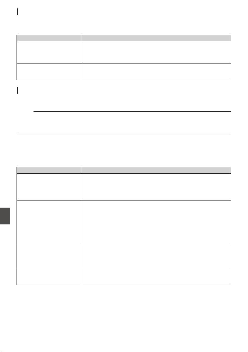
Blinking of the Tally Lamp
The tally lamp start blinking when the remaining space on the SD card is running out during recording, or
when the battery power is running low.
(Common for front and back tally lamps)
Blinking Mode Remaining Battery Power/SD Card Space
Blinks slowly
(once every second)
0
Battery power is low
0
Remaining recording time on SD card is less than 3 minutes (during
recording)
0
When a malfunction occurred during live streaming
Blinks quickly
(2 times per second)
0
Remaining battery power is almost zero
0
Remaining recording time on SD card is zero (during recording)
0
Error on the camera recorder
Warning Tone
0
Warning tone is output from the monitor speaker and [PHONES] terminal when the battery level is low.
0
Warning tone is also output when an error occurs in the camera recorder.
Memo :
0
You can specify whether to turn on the warning tone as well as setting the volume in [A/V Set] B [Audio
Set] B [Alarm Level].
(A P129 [ Alarm Level ] )
Troubleshooting
Symptom Action
Power does not turn on.
0
Is the power supply or battery properly connected?
0
Is the battery charged?
0
Is the power turned on immediately after it is turned off?
Make sure to wait for an interval of at least 5 seconds before turning
on the power again.
Unable to start recording.
0
Is the record trigger button/lock switch on the handle turned on?
0
Is the write-protect switch of the SD card turned on?
Make sure that the write-protect switch is turned off.
(A P43 [Write-Protect Switch on the SD Card] )
0
Is the camera recorder set to the Camera mode?
Press the [CAM/MEDIA] selection button to switch to the Camera
mode.
(A P18 [Operation Modes] )
Camera image is not output on
the LCD monitor and
viewfinder screen.
0
Is the camera recorder set to the Camera mode?
Press the [CAM/MEDIA] selection button to switch to the Camera
mode.
(A P18 [Operation Modes] )
Playback does not start after
selecting a clip thumbnail and
pressing the Set button (R).
0
Is the selected clip a playable clip?
Playback is not possible if the clip has a different video format setting.
206
Error Messages and Actions
Others

Symptom Action
No sound during playback.
0
Is the currently played clip recorded in the Variable Frame Rec mode?
(A P93 [Variable Frame Rec] )
Images on the LCD monitor
and viewfinder screen appear
dark or blurred.
0
Readjust the brightness of the LCD monitor and viewfinder.
0
Is the [ND FILTER] switch set to “1/64”?
0
Is the iris closed?
0
Is the shutter speed setting too high?
0
Is the amount of peaking too little? Use the [PEAKING +/-] button to
adjust the contour for the LCD monitor and the viewfinder screen.
(A P39 [Adjusting the LCD Monitor] )
(A P40 [Adjusting the Viewfinder] )
The [CH-1/CH-2] recording
level adjustment knob does
not work.
0
Is the [CH-1/CH-2 AUTO/MANUAL] switch set to “AUTO”?
0
Is the [FULL AUTO] switch set to “ON”?
Is the [FULL AUTO] switch set to “ON”, and [Camera Function] B
[FULL AUTO] B [Audio] set to “Auto”?
(A P114 [ Audio ] )
[CH-3/CH-4] audio is not
recorded.
0
Is the number of recording channels set to “4ch”?
(A P133 [ W Audio ] )
(A P134 [ Y Audio ] )
0
Is [System] B [Record Set] B [Record Format] B [WFormat]/
[YFormat] set to “AVCHD”? Select a setting other than “AVCHD”.
(A P133 [ W Format ] )
(A P134 [ Y Format ] )
SD card cannot be initialized
(formatted).
0
Is the write-protect switch of the SD card turned on?
Make sure that the write-protect switch is turned off.
(A P43 [Write-Protect Switch on the SD Card] )
Battery alarm appears even
after loading a charged
battery.
0
Is the battery too old?
Menu cannot be operated.
0
Is the Menu Lock mode turned on?
(A P106 [About the Menu Lock Feature] )
The time code and user’s bit
are not displayed.
0
Even in Camera mode or Media mode, the time code and user’s bit
may not be displayed depending to the type of display.
0
Is [LCD/VF] B [Display Settings] B [TC/UB] set to “Off”? To display
the time code or user’s bit, set it to “TC” or “UB”.
(A P123 [ TC/UB ] )
The date and time are not
displayed.
0
The date and time are only displayed on the Display 1 and Display 2
screens in the Camera mode (during shooting).
(A P145 [Display Screen in Camera Mode] )
0
Is [System] B [Record Set] B [Time Stamp] set to “On”? To display
the date and time, set it to “Off”.
(A P136 [ Time Stamp ] )
Troubleshooting
207
Others

Symptom Action
Incorrect display on the
viewfinder.
0
Is the LCD monitor used with [LCD/VF]
B
[LCD + VF] set to “Off”?
(A P120 [ LCD + VF ] )
The actual recording time is
shorter than the estimated
time.
0
The recordable time may be shorter depending on the shooting
conditions or the subject.
The two camera recorders are
not synchronized even though
the time codes have been
synchronized. (Z on the Slave
device is not displayed.)
0
Is the [TC GENE.] switch set to “FREE”?
(A P78 [Synchronizing the Time Code with an External Time Code
Generator] )
0
Set [System] B [Record Set] B [Record Format] B [WFrame & Bit
Rate] such that the two camera recorders have the same frame rate.
(A P133 [ W Frame & Bit Rate ] )
Cannot connect to wireless
LAN.
0
Check the mode of connection and method of setting ([SSID] and
[Passphrase] in cases other than WPS).
(A P175 [Connecting via Wireless LAN] )
0
Even if the Passphrase is wrong, “Completed the Setup Wizard.
Please Input the Passphrase into Your Device.” may appear at the
browser setting depending on the type of encryption.
Adjust [Passphrase] again.
The View Remote screen turns
black.
The screen flickers.
The screen freezes.
Cannot perform remote
operation.
0
The network path is congested.
Wait a while before refreshing (reloading) the web browser.
0
The problem may be resolved by clearing the web browser cache.
The clips cannot be uploaded
to the FTP server.
0
Adjust the [Clip Server] settings.
(A P140 [ Clip Server ] )
0
The maximum size of the recorded clip is 64 GB.
If a file size limit is set in the FTP server settings, set the size limit to
more than 64 GB.
0
Take necessary action as described in “[List of FTP Transfer
Errors] P 203”.
The wireless LAN is
disconnected.
0
The wireless LAN may be disconnected depending on the
environment. Change the usage environment.
0
Connect via wired LAN.
(A P177 [Connecting via Wired LAN] )
GPS signal cannot be
received.
0
Signal reception from GPS satellites may be affected by buildings or
trees.
Perform positioning preferably at an unobstructed location with a clear
view.
0
Radio wave reception may be affected by weather conditions such as
on a cloudy or rainy day.
The position is not accurate.
0
The precision error may be up to hundreds of meters if the GPS signal
is weak or reflected off surrounding buildings.
208
Troubleshooting
Others
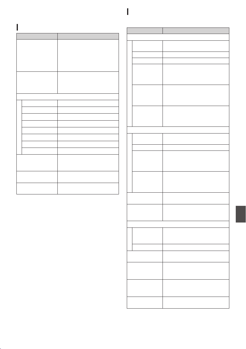
Specifications
General
Item Description
Power When using an external
power source:
DC 10.5 V to 17.0 V
When using a battery:
DC 14.4 V (Anton/Bauer,
IDX)
Power
consumption
Approx. 21.0 W
(during recording [camera
recorder + supplied lens]
while using the viewfinder)
Mass
GY-HM890U 3.95 kg (*1)
GY-HM890E 4.15 kg (*1)
GY-HM890CHU 2.7 kg (*2)
GY-HM890CHE 2.9 kg (*2)
GY-HM850U 3.9 kg (*1)
GY-HM850E 4.1 kg (*1)
GY-HM850CHU 2.65 kg (*2)
GY-HM850CHE 2.85 kg (*2)
Allowable
operating
temperature
0 °C to 40 °C (32 °F to 104 °F)
Allowable
operating humidity
35 %RH to 80 %RH
Allowable storage
temperature
-20 °C to 50 °C (-4 °F to 122
°F)
*1 Camera recorder (including microphone and
viewfinder) and supplied lens
*2 Camera recorder (including microphone and
viewfinder) only
Terminal Section
Video/Audio
Item Description
[HD/SD SDI OUT] Terminal (BNC)
HD-SDI
(1080i/720p)
Compliant with SMPTE 292 M
SD-SDI Compliant with SMPTE 259 M
3G-SDI Compliant with SMPTE 424 M
HD-SDI
embedded
audio
standard
Compliant with SMPTE 299 M
SD-SDI
embedded
audio
standard
Compliant with SMPTE 272 M
3G-SDI
embedded
audio
standard
Compliant with SMPTE 299 M
[HD/SD SDI IN] Terminal (BNC) A B
HD-SDI
(1080i/720p)
Compliant with SMPTE 292 M
SD-SDI Compliant with SMPTE 259 M
HD-SDI
embedded
audio
standard
Compliant with SMPTE 299 M
SD-SDI
embedded
audio
standard
Compliant with SMPTE 272 M
[VIDEO OUT]
Terminal (BNC)
1.0 V (p-p), 75 K (unbalanced)
[HDMI] Output
Terminal (Type
A)
V1.3-compliant
[INPUT1/INPUT2] Terminal (XLR 3-pin)
[MIC] -50 dBu, 3 kK, XLR (balanced),
+48 V output (phantom power
supply)
[LINE] +4 dBu, 10 kK, XLR (balanced)
[AUX] Terminal -22dBu, 10 kK, φ3.5 mm stereo
mini jack (unbalanced)
[AUDIO
OUTPUT CH-1/
CH-3] Terminal
-8 ± 1 dBu (during reference
level input), 1 kK (unbalanced)
[AUDIO
OUTPUT CH-2/
CH-4] Terminal
-8 ± 1 dBu (during reference
level input), 1 kK (unbalanced)
[PHONES]
Terminal
φ3.5 mm stereo mini jack
(unbalanced) x 2
Specifications
209
Others
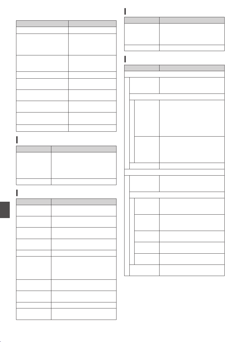
Others
Item Description
[GENLOCK] Terminal 1.0 V (p-p), 75 K
[DEVICE] Terminal Mini USB-B type, USB
2.0, miniB, slave
function (mass storage
class) only
[HOST] Terminal USB-A type, USB2.0,
network connection
function only, 5 V/0.5 A
[REMOTE1] Terminal miniDin 6-pin
[REMOTE2] Terminal φ2.5 mm wired remote
control
[TC IN] Terminal 1.0 V(p-p) to 4.0 V(p-p)
high impedance
[TC OUT] Terminal 1.0 V(p-p) to 4.0 V(p-p)
low impedance
[STUDIO]
Terminal A B
miniDin
[DC INPUT] Terminal XLR 4-pin
Lens Section A C
Item Description
Lens F1.6 (wide-angle) to F3.0
(telephoto)
f = 4.1 mm to 82.0 mm
(Conversion to 35 mm camera
format: f = 29 mm to 580 mm)
Filter Diameter Φ72 mm
Camera Section
Item Description
Image pickup
device
1/3-inch, 2.2 megapixels,
progressive CMOS x 3
Color separation
prism
F1.6, 3-color separation prism
Sensitivity F11, 2000 lx (standard value: 60
Hz)
Sync system External/Internal
Synchronization (Built-in SSG)
Optical filter OFF, 1/4, 1/16, 1/64
Gain -6 dB, -3 dB, 0 dB, 3 dB, 6 dB,
9 dB, 12 dB, 15 dB, 18 dB,
21 dB, 24 dB, Lolux (30 dB,
36 dB), ALC
Electronic
shutter
1/4 to 1/10000, EEI
Variable Frame
Rate
2/30-60/30fps, 2/25-50/25fps,
2/24-60/24fps
LCD monitor 4.3-inch LCD, 1.15 megapixels
Viewfinder 0.45-inch LCOS, 1.22M pixels
(852 x 480 x 3)
Storage Section
Item Description
Supported
media
SDHC/SDXC memory card
(Class 4/6/10)
* Class 4 supports only AVCHD/
SD/Web formats.
Slots x 2
Video/Audio
Item Description
HD mode (MOV/MP4/MXF: MPEG-2)
Video
recording file
format
QuickTime File Format (For
Final Cut Pro)/MP4 File Format/
MXF File Format
Video
HQ Mode MPEG-2 Long GOP VBR, 35
Mbps (Max) MP@HL,
1920x1080/59.94i, 29.97p,
23.98p, 50i, 25p,
1440x1080/59.94i, 50i,
1280x720/59.94p, 29.97p,
23.98p, 50p, 25p
SP Mode MPEG-2 Long GOP CBR, 18.3
Mbps MP@HL (720 p)/25 Mbps
MP@H14 (1080i)
1440x1080/59.94i, 50i,
1280x720/59.94p, 50p
Audio LPCM 2ch/4ch, 48 kHz/16 bits
HD Mode (AVCHD)
Video
recording file
format
AVCHD File Format
Video
HQ Mode
(Progressive)
MPEG-4 AVC/H.264, 28 Mbps
(Max)
1920x1080/59.94p, 50p
HQ Mode MPEG-4 AVC/H.264, 24 Mbps
(Max)
1920x1080/59.94i, 50i
SP Mode MPEG-4 AVC/H.264, 17 Mbps
1920x1080/59.94i, 50i
LP Mode MPEG-4 AVC/H.264, 9 Mbps
1440x1080/59.94i, 50i
EP Mode MPEG-4 AVC/H.264, 5 Mbps
1440x1080/59.94i, 50i
Audio Dolby Digital 2ch, 48 kHz/16
bits, 256 kbps
210
Specifications
Others
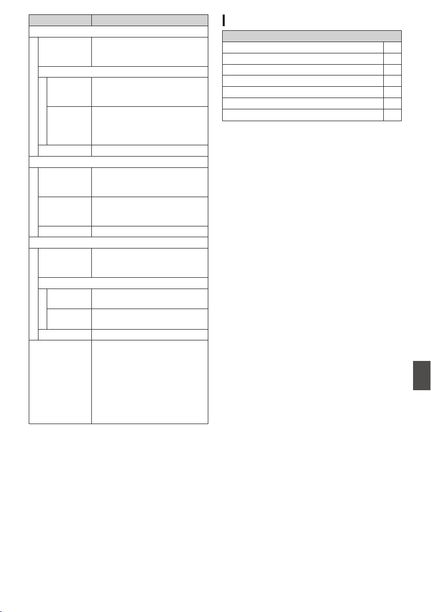
Item Description
HD Mode (MOV: H.264)
Video
recording file
format
QuickTime File Format
Video
XHQ Mode MPEG-4 AVC/H.264, 50 Mbps
1920x1080/59.94p, 59.94i,
29.97p, 23.98p, 50p, 50i, 25p
UHQ Mode MPEG-4 AVC/H.264, 35 Mbps
(Max)
1920x1080/59.94i, 30p,
23.98p, 50i, 25p
Audio LPCM 2ch/4ch, 48 kHz/16 bits
SD mode (MOV: H.264)
Video
recording file
format
QuickTime File Format
Video MPEG-4 AVC/H.264, 8 Mbps
720×480/59.94i (U model)
720×576/50i (E model)
Audio LPCM 2ch/4ch, 48 kHz/16 bits
Web Mode (MOV: H.264)
Video
recording file
format
QuickTime File Format
Video
HQ Mode MPEG-4 AVC/H.264, 3 Mbps
960x540/29.97p, 23.98p, 25p
LP Mode MPEG-4 AVC/H.264, 1.2 Mbps
480x270/29.97p, 23.98p, 25p
Audio μ-law 2ch/4ch, 16 kHz
Streaming Mode 1920x1080 (60i/50i) Audio
AAC128 k 8/5/2.5 Mbps
1280x720 (30p/25p) Audio
AAC128 k 5/3/1.5 Mbps
720x480 (60i) 720x576 (50i)
Audio AAC128 k/64 k/32 k
5/3/1.5/0.8/0.3/0.2 Mbps
480x270 (30p/25p) Audio AAC
32 k 0.2 Mbps
Accessories
Accessories
Warranty Card (U model only) 1
Anti-reflective Film 1
Instructions 1
Documents and Software Disc 1
Viewfinder 1
Microphone 1
Lens A C 1
Specifications
211
Others
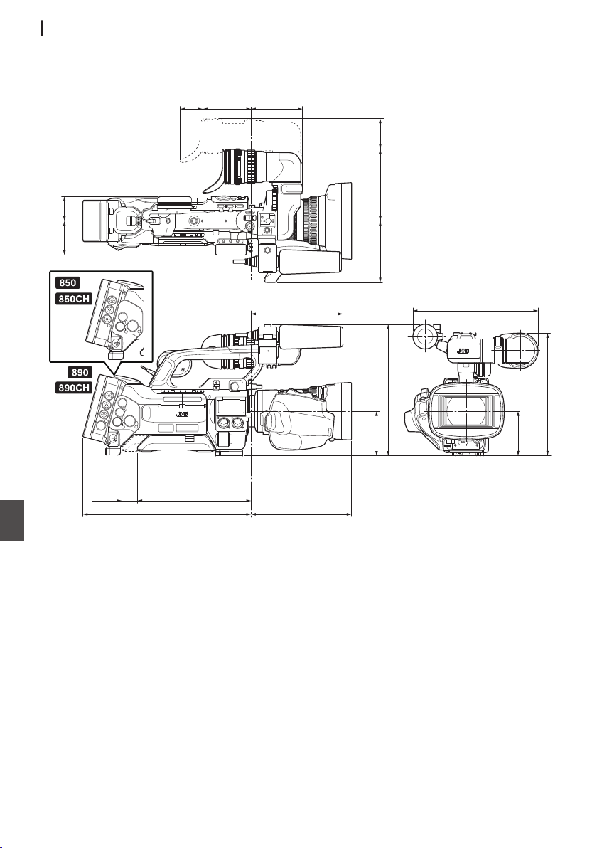
Dimensional Outline Drawing (Unit: mm)
GY-HM890U/GY-HM890CHU/GY-HM850U/GY-HM850CHU
.
90
95
114 133 56
44.662.5
231
(166)
185.5311
242.3
225
82.3
(82.3)
209
30
40
(VF MOVE)
(VF MOVE)
(S.PAD
MOVE)
212
Specifications
Others
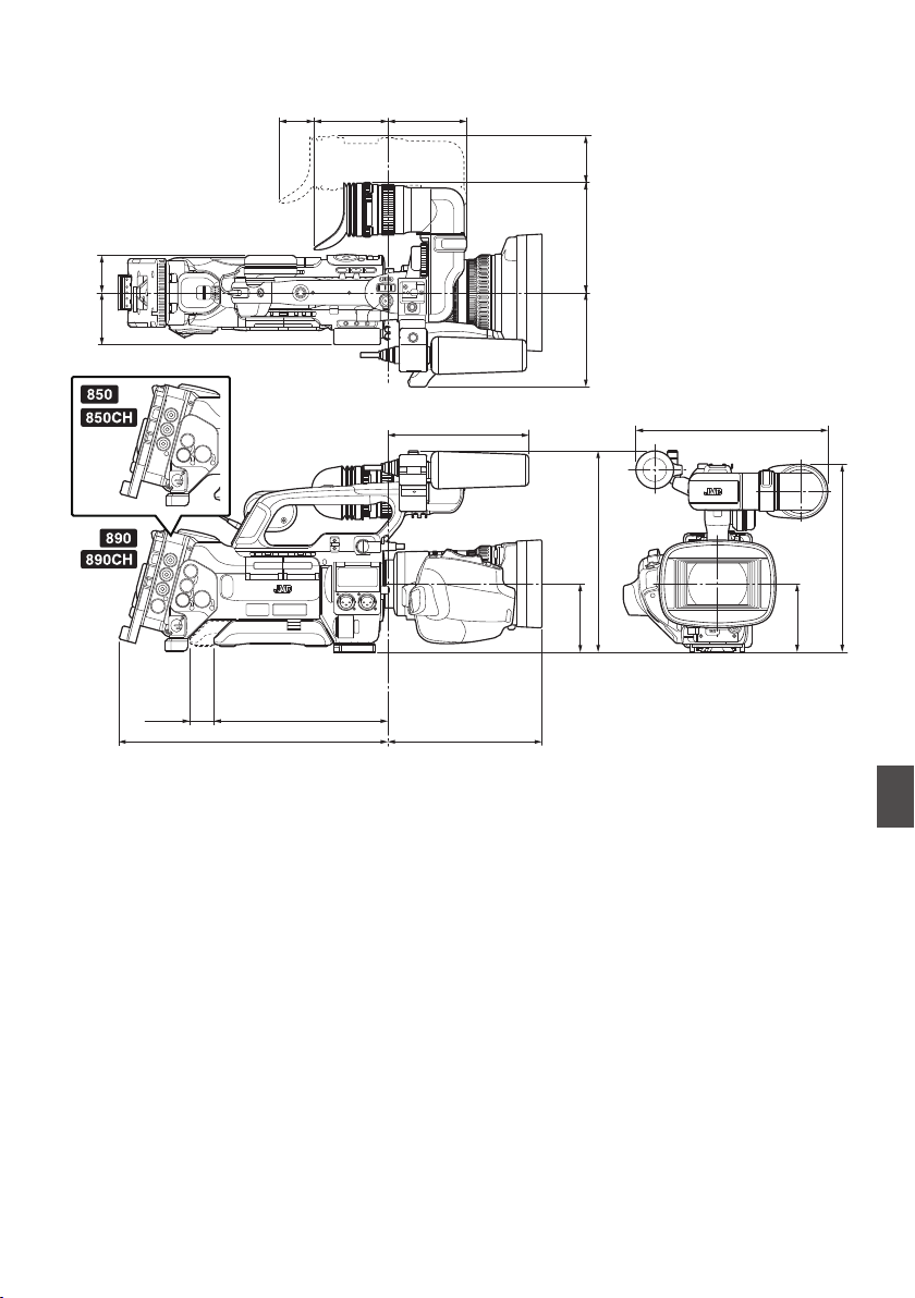
GY-HM890E/GY-HM890CHE/GY-HM850E/GY-HM850CHE
.
90 95
114 133
(VF MOVE)
56
44.662.5
231
(166)
185.5324
242.3
225
82.3
(82.3)
209
30
(S.PAD
MOVE)
(VF MOVE)
40
* The specifications and appearance of this product are subject to changes for further improvement without
prior notice.
Specifications
213
Others

Index
A
AC Adapter ................................................ 30
Access point ............................................ 175
Action ........................................................ 96
Anti-reflective film ...................................... 30
Aspect ratio ................................................ 50
B
Back focus ................................................. 41
Backup rec ................................................ 87
Battery ................................................. 15, 31
Brightness adjustment ............................... 57
C
Camera mode .............................. 19, 36, 145
Cellular adapter ....................................... 177
Clip continuous rec .................................... 89
Clip cutter trig (splitting clips) ..................... 85
Clip name ............................................. 47, 95
Clip review ................................................. 83
Color bar .................................................. 155
Color matrix ............................................. 156
Computer ................................................. 160
Connection settings file ............................ 197
Continuous operating time ......................... 31
D
Deleting clips ............................................. 98
Display screen ........................... 36, 145, 151
Dual rec ..................................................... 85
E
Earphone ........................................... 72, 163
Editing clip metadata ............................... 184
Error message ................................... 64, 202
Expanded focus ......................................... 55
External monitor ....................................... 161
F
Face detection ........................................... 56
Favorites menu ........................................ 142
File format .................................................. 50
Focus ......................................................... 53
Focus assist ............................................... 55
Formatting (initializing) SD cards ............... 45
Frame rec .................................................. 91
FTP server ................................. 97, 178, 180
G
Gain adjustment ........................................ 59
Genlock ........................................... 126, 169
GPS ............................................. 15, 82, 147
Grid marker ...................................... 121, 154
H
Histogram .......................................... 84, 123
I
Image stabilizer .......................................... 68
Initial settings ............................................. 34
Interval rec ................................................. 92
Iris adjustment ........................................... 58
L
LCD monitor ............................. 15, 32, 36, 39
Lens cover ................................................. 29
Live streaming ......................................... 199
M
Marker display ......................................... 154
Media mode ................................. 19, 37, 151
Menu ........................................ 103, 104, 107
Menu lock ................................................ 106
Metadata .......................................... 178, 183
Monitor speaker ......................................... 40
N
ND filter ...................................................... 62
Network ........................................... 149, 174
Network operating environment ............... 174
O
OK mark .................................................... 99
One push auto focus .................................. 54
Operation lock ........................................... 48
P
P2P .......................................................... 176
Picture file ................................................ 157
Picture quality setting ................................. 68
Power .................................................. 32, 33
Pre rec ....................................................... 89
Preset zoom .............................................. 52
Preset zoom (camera) ............................... 52
Preset zoom (web browser) ..................... 191
Push auto focus ......................................... 54
R
Recordable time ........................................ 43
Remote control unit ............................ 24, 164
Remote edit mode ............................... 19, 38
Resolution .................................................. 50
Restoring SD card ..................................... 46
Return Videos .................................. 127, 172
S
Safety zone display .................................. 154
SD/SDHC/SDXC card ......................... 16, 43
SDI input .................................... 24, 132, 168
Selecting multiple clips ............................ 100
Setting the date/time .................................. 35
Setup file .................................................. 157
Shooting .................................................... 49
Skin detail function ................................... 155
Software Keyboard .................................. 105
Spot meter ................................................. 80
Status screen ..................................... 37, 153
Studio system .......................................... 172
Switching shutter mode ............................. 60
214
Index
Others

Switching shutter speed ............................ 60
T
Tally lamp .......................................... 42, 206
Thumbnail (detailed screen) ...................... 96
Thumbnail (standard screen) ..................... 94
Thumbnail screen ...................................... 94
Time code ...................................... 72, 73, 78
Time code generator ................................. 73
Time code playback ................................... 98
Trimming .................................................. 102
U
USB mode ................................... 19, 38, 160
User button ................................................ 42
User’s bit .................................................... 72
V
Variable frame rec ..................................... 93
Video format .............................................. 50
View remote ............................................. 190
Viewfinder ................................ 15, 32, 36, 40
W
Warning ............................................. 38, 206
White balance adjustment ......................... 63
White paint ................................................. 65
White shading .................................... 66, 118
Wired LAN ............................................... 177
Wired remote control ............................... 164
Wireless LAN ........................................... 175
Z
Zebra pattern ............................................. 79
Zoom ......................................................... 52
Symbol
4 channel (audio) ............................... 69, 127
Index
215
Others

Software License
Agreement
The software embedded in the Product (hereinafter
the “Licensed Software”) provided by
JVC KENWOOD Corporation (hereinafter the
“Licensor”) is copyrighted to or sublicensable by
the Licensor, and this Agreement provides for the
terms and conditions which Users shall follow in
order to use the Licensed Software. The User shall
use the Licensed Software by agreeing with the
terms of this Software License Agreement. This
Agreement shall be deemed completed at the time
the User (hereinafter the “User”) initially used the
Product in which the “Licensed Software” is
embedded.
The Licensed Software may include the software
which has been licensed to the Licensor directly or
indirectly from any third party. In such case, some
third parties require the Users to follow their
conditions for use separately from this Software
License Agreement. Such software shall not be
subject to this Agreement, and the Users are urged
to read the “[Important Notice concerning the
Software] P 217” to be provided separately.
Article 1 General Provision
The Licensor shall grant to the User a non-
exclusive and non-transferable (other than the
exceptional case referred to in Article 3, Paragraph
1) licensed to use the Licensed Software within the
country of the User (the country where the User
bought the Product (hereinafter the “Country”)).
Article 2 License
1. The license granted under this Agreement shall
be the right to use the Licensed Software in the
Product.
2. The User shall not duplicate, copy, modify, add,
translate or otherwise alter, or lease the Licensed
Software and any related documents, whether in
whole or in part.
3. The use of the Licensed Software shall be limited
to personal purpose, and the Licensed Software
shall not be distributed, licensed or sub-licensed
whether it is for commercial purpose or not.
4. The User shall use the Licensed Software
according to the directions described in the
operation manual or help file, and is prohibited to
use or duplicate any data in a manner violating the
Copyright Law or any other laws and regulations by
applying whole or a part of the Licensed Software.
Article 3 Conditions for Grant of License
1. When the User transfers the Product, it may also
transfer the license to use the Licensed Software
embedded in the Product (including any related
materials, updates and upgrades) on condition that
no original, copies or related materials continue in
the possession of the User, and that the User shall
cause the transferee to comply with this Software
License Agreement.
2. The User shall not carry out reverse engineering,
disassembling, decompiling or any other code
analysis works in connection with the Licensed
Software.
Article 4 Right pertaining to the Licensed
Software
1. Any and all copyrights and other rights pertaining
to the Licensed Software and related documents
shall belong to the Licensor or the original holder
of the right who granted to the Licensor the license
or sublicense for the Licensed Software
(hereinafter the “Original Rightholder”), and the
User shall not be entitled to any right other than the
license granted hereunder, in respect of the
Licensed Software and any related documents.
2. The User shall, whenever the User uses the
Licensed Software, comply with any laws relating
to the copyright and other intellectual property
rights.
Article 5 Indemnification of Licensor
1. Neither the Licensor nor the Original Rightholder
shall be liable for any damage incurred by the User
or any third party due to the exercise of the license
granted to the User under this Agreement, unless
otherwise restricted by law.
2. The Licensor will offer no guarantee for the
merchantability, convertibility and consistency with
certain objective of the Licensed Software.
Article 6 Liability to Third Party
If any dispute has arisen with any third party due to
an infringement upon a copyright, patent or any
other intellectual property right that was caused by
the User’s use of the Licensed Software, the User
shall settle such dispute at the User’s own cost and
hold the Licensor and the Original Rightholder
harmless from any inconvenience it may cause.
Article 7 Confidentiality
The User shall keep the confidentiality of such
portion of the Licensed Software, related
documents thereof or any other information to be
granted under this Agreement, as well as the
conditions of this Agreement as has not yet entered
the public domain, and shall not disclose or divulge
the same to any third party without approval of the
Licensor.
216
Software License Agreement
Others

Article 8 Termination
In case the User falls under any of the events
described in the following items, the Licensor may
immediately terminate this Agreement or claim that
the User compensates for the damage incurred by
the Licensor due to such event:
(1) when the User violated any provision of this
Agreement; or
(2) when a petition has been filed against the User
for an attachment, provisional attachment,
provisional disposition or any other compulsory
execution.
Article 9 Destruction of the Licensed Software
If this Agreement is terminated pursuant to the
provision of Article 8, the User shall destroy the
Licensed Software, any related documents and
copies thereof within two (2) weeks from such date
of termination.
Article 10 Export Restriction
1. The User shall understand that the Licensed
Software shall be subject to the export restrictions
adopted by the country of User and any other
countries.
2. The User shall agree that the software will be
subject to any and all applicable international and
domestic laws including the export control
regulation of the country of User and any other
countries, and any restrictions concerning the end-
users, the use by end-users and importing
countries to be provided by the country of User and
any other countries, and any other governmental
authorities.
3. If the User is an agency of the United States of
America (the “Government”), the User
acknowledge Licensor’s representation that the
Licensed Software is a “Commercial Item” as
defined in Federal Acquisition Regulation (FAR)
part 2.101(g) consisting unpublished “Commercial
Computer Software” as those items are used at
FAR part 12.212 and is only license the User with
the same use right Licensor grants all commercial
end users pursuant to the terms of this Agreement.
Article 11 Miscellaneous
1. In the event any part of this Agreement is
invalidated by operation of law, the residual
provisions shall continue in force.
2. Matters not stipulated in this Agreement or any
ambiguity or question raised in the construction of
this Agreement shall be provided or settled upon
good-faith consultation between the Licensor and
the User.
3. The Licensor and the User hereby agree that this
Agreement is governed by the laws of Japan, and
any dispute arising from, and relating to the rights
and obligations under, this Agreement shall be
submitted to the exclusive jurisdiction of the Tokyo
District Court for its first instance.
Important Notice
concerning the Software
Software License Attached to the Product :
The Software embedded in the Product is
composed of several independent software
components, and in each of such individual
components (hereinafter the “Licensed Software”),
a copyright of either JVC KENWOOD Corporation
(hereinafter “JKC”) or a third party subsists.
The Product uses the software component
designated in the End-User License Agreement
that was executed between JKC and a third party
(hereinafter “EULA”).
The Licensed Software covers those
corresponding to free software, and, as a condition
of distribution of the software component in
executable format which is based on the license
granted under the GNU General Public License or
Lesser General Public License (hereinafter “GPL/
LGPL”), it requires an availability of the source
code for the relevant component. Please refer to
the following URL concerning the distribution of the
source code;
http://www3.jvckenwood.com/english/
download/gpl/index.html
Please note that we are unable to answer any
inquiry relating to the contents, etc. of the source
code. In addition, the Licensed Software includes
the software developed or created independently
by JKC and there exists an ownership of JKC in
such software and any accompanying documents,
which is protected by the Copyright Law, any
international treaties and other applicable laws. As
to matters concerning the handling by JKC of the
software components, please refer to the
“Software License Agreement” attached hereto.
Please note that any software component licensed
under “EULA” which is not subject to “GPL/LGPL”,
and those developed or created independently by
JKC shall not be subject to the requirement for
provision of the source code. The software
component distributed under “GPL/LGPL” shall be
licensed to users without charge, and, therefore, no
warranty is given for such software component,
either express or implied, within the scope of the
applicable laws and regulations. Unless otherwise
permitted by applicable laws and regulations or
agreed in written form, none of the owners of the
copyright or persons entitled to alter or redistribute
the software component under the said license
shall have any liability for any type of damage or
loss resulting from the use of or inability to use such
software component. For further details of the
conditions of use of such software component or
matters required to be complied with, please refer
to the relevant “GPL/LGPL”.
Users are urged to read the details for the relevant
license carefully before using the software
component covered by “GPL/LGPL” and
embedded in the Product. Since the terms and
conditions of individual licenses are provided by
parties other than JKC, the original English version
will be displayed by the Product.
Software License Agreement
217
Others

A
Turn on the power.
B
Press the [MENU/THUMB] button.
C
Select [Main Menu] B [System] B [System
Information] B [Open Source License].
Open Source License
SGI FREE SOFTWARE LICENSE B (Version 2.0)
0
OpenGL ES1.1 (Header file)
0
EGL1.1 (Header file)
SGI FREE SOFTWARE LICENSE B (Version 2.0,
Sept. 18, 2008)
Copyright © [dates of first publication] Silicon
Graphics, Inc. All Rights Reserved.
Permission is hereby granted, free of charge, to
any person obtaining a copy of this software and
associated documentation files (the “Software”), to
deal in the Software without restriction, including
without limitation the rights to use, copy, modify,
merge, publish, distribute, sublicense, and/or sell
copies of the Software, and to permit persons to
whom the Software is furnished to do so, subject to
the following conditions:
The above copyright notice including the dates of
first publication and either this permission notice or
a reference to http://oss.sgi.com/projects/FreeB/
shall be included in all copies or substantial
portions of the Software.
THE SOFTWARE IS PROVIDED “AS IS”,
WITHOUT WARRANTY OF ANY KIND,
EXPRESS OR IMPLIED, INCLUDING BUT NOT
LIMITED TO THE WARRANTIES OF
MERCHANTABILITY, FITNESS FOR A
PARTICULAR PURPOSE AND
NONINFRINGEMENT. IN NO EVENT SHALL
SILICON GRAPHICS, INC. BE LIABLE FOR ANY
CLAIM, DAMAGES OR OTHER LIABILITY,
WHETHER IN AN ACTION OF CONTRACT,
TORT OR OTHERWISE, ARISING FROM, OUT
OF OR IN CONNECTION WITH THE SOFTWARE
OR THE USE OR OTHER DEALINGS IN THE
SOFTWARE.
Except as contained in this notice, the name of
Silicon Graphics, Inc. shall not be used in
advertising or otherwise to promote the sale, use
or other dealings in this Software without prior
written authorization from Silicon Graphics, Inc.
218
Important Notice concerning the Software
Others

219

.
GY-HM890U/GY-HM890E/GY-HM890CHU/GY-HM890CHE/
GY-HM850U/GY-HM850E/GY-HM850CHU/GY-HM850CHE
HD MEMORY CARD CAMERA RECORDER
© 2014 JVC KENWOOD Corporation
LST1584-001A