Loading ...
Loading ...
Loading ...
&
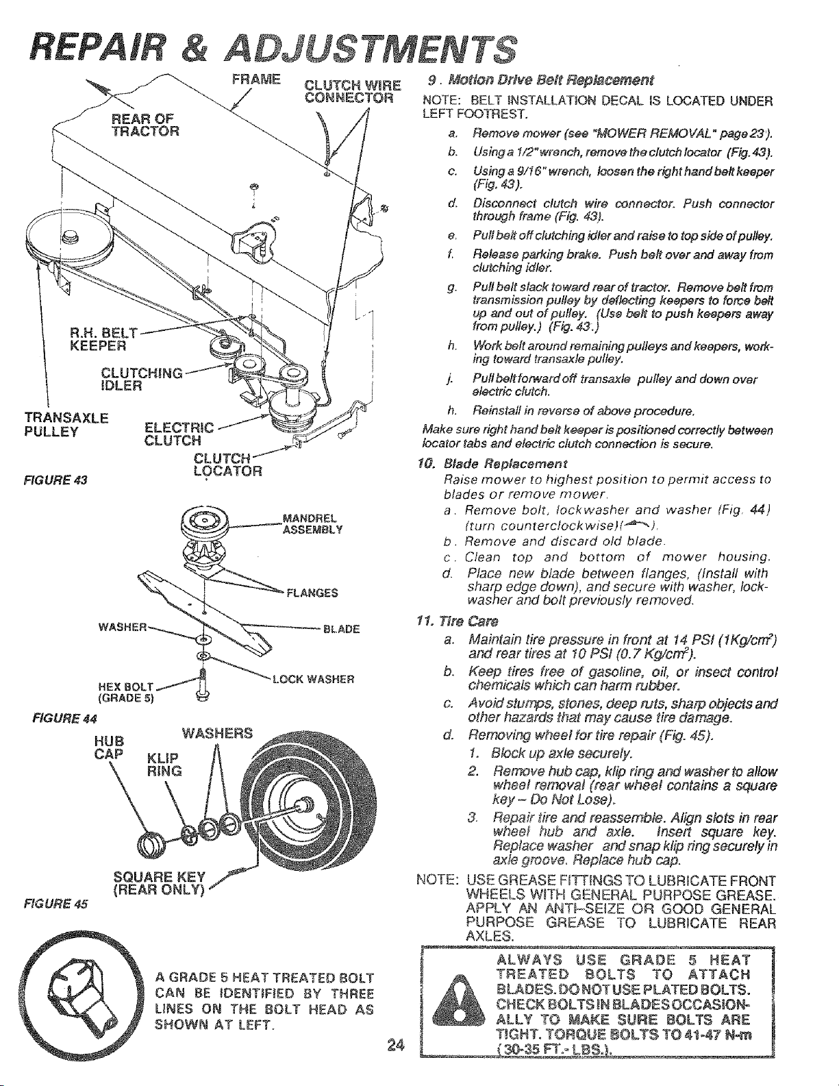
FRAME
TRANSAXLE
PULLEY
FIGURE 43
CLUTCH|NI
iDLER
ELECTRIC
CLUTCH
CLUTCH
LOCATER
SQUARE KEY
(REAR ONLY)
FIGURE 45
A GRADE 5 HEAT TREATED BOLT
CAN BE IDENTiFiED BY THREE
UNES ON THE BOLT HEAD AS
SHOWN AT LEFT.
2,$
9. Motion Drfve Bait Rept,_coment
NOTE: BELT INSTALLATION DECAL iS LOCATED UNDER
LEFT FOOTREST.
a. Remove mower (see "MOWER REMOVAL" page23).
b. Usinga 1/2"wrench, removethectutchlecater (Fig,43),
c. Using a 9116" wrench, l_sen the right hand be# keeper
(Fig, 43).
d. Disconnect clutch wire connector. Push connector
through frame (Fig. 43).
e. Pull be# off clutching idler and raise to top side of pulley,
f. Release parking brake. Push be# ever and away from
clutching idler.
g. Pull belt slack toward rear ef tractor, Remove be# from
transmission pulley by deflecting keepers to force belt
up and out of pulley. (Use belt to push keepers away
from pulley.) (Fig. 43:)
h. Work belt around remaining pulleys and keepers, work-
ing toward transaxle pulley.
j. Pull be#fomcard off transaxle pulley and down over
electric clutch.
h. Reinstall in reverse of above procedure,
Make sure right hand be# keeper is positioned correctly between
locater tabs and electric clutch connection is secure.
10, Blade Replacement
Raise mower to highest position to permit access to
blades or remove mower.
a. Remove bolt, Iockwasher and washer (Fig. 44)
(turn counterclockwiset(_'_" ).
b. Remove and discard old blade.
c. Clean top and bottom of mower housing.
d. Place new blade belween flanges, (install with
sharp edge down), and secure with washer, lock-
washer and bolt previously removed.
11. Tire Csre
a. Maintain tire pressure in front at 14 PSi (1Kg/cm 2)
and rear tires at I0 PSi (0. 2"Kg/cm2).
b. Keep tires free of gasoline, oil, or insect control
chemicals which can harm nJbbero
& Avoid stumps, stones, deep ruts, sharp objects and
other hazards that may cause tire damage.
do Removing wheel for tire repair (Fig. 45).
1. Block up axle securely.
2. Remove hub cap, ktip ring and washer to allow
whee! removal (rear wheel contains a square
key - Do Not Lose).
3. Repair tire and reassemble. Align slots in rear
whee_ hub and _le. fnsert square key.
Replace washer and snap klip ring securely in
axle groov& Replace hub cap.
USE GREASE F_TTINGS TO LUBRICATE FRONT
WHEELS W_TH GENERAL PURPOSE GREASE.
APPLY AN ANT_-SEIZE OR GOOD GENERAL
PURPOSE GREASE TO LUBRICATE REAR
AXLES.
NOTE:
ALWAYS USE GRADE 5 HEAT
TREATED BOLTS TO ATTACH
BLADES. DO NOTUSE PLATED BOLTS.
CHECK E_OLTS _N8LADES OCCASJONo
ALLY TO MAKE SURE BOLTS ARE
T_GNT. TORQNE 8OLTS TO 41-47 N-m
Loading ...
Loading ...
Loading ...