
OWNER'S
MANUAL
MODEL NO.
917.254450
AND
917.250020
WITHOUT
MOWER DECK
CautiGn:
Read and follow
all Safety Rules
and instructions
Before Operating
This Equipment
®
18.0 P TWI IC
ELECTRIC START
44"MOWER DECK
6 PE TRANSAXLE
GA TRACTO
• Assembly
• Operation
• Maintenance
. Service and Adjustment
• Repair Parts
Sears, Roebuck and Co., Chicago, iL _684 U.S.A.

CAUTION: LOOK FOR THIS WORD TO POINT OUT
_MPORTANT EQUIPMENT PRECAUTIONS,
NOTE: LOOK FOR THIS WORD TO POINT OUT IM-
PORTANT _NFORMATION ABOUT THE OPERATION
AND PERFORMANCE OF YOUR TRACTOR.
RULES FOR SAFE OPERATION
WARNING: This unit Jsequipped with an internal combustion engine and should not be used on or near any unimproved forest covered,
brush covered or grass covered land unless the engine s exhaust system is equipped with a spark attester meetingapplicable local or area
laws (if any). Ifa spark arrestor is used, it should be maintained in effective working order by the operator. (See REPAIR PARTS for part
numoer identification).
In the State of California the above is required by law (Section 4442 of the California Public Resources Code). Other States may have similar
laws. Federal laws,apply on federal lands.
1. Know the controls and how to stop quickly. READ THIS
OWNER S MANUAL and instructions furnished with attach-
ments.
2. Do not allow chiidren to operate the machine. Do not allow
adults to operate it without proper instruction.
3. Do not carry passengers. Do not mow when children and
others are around.
4. Always wear substantial footwear. Do not wear loose fitting
clothing that could get caught in moving parts.
5. Keep your eyes and mind on your tractor mower, and the
area being cut. Do not let other interests distract you.
6. Do not attempt to operate your tractor or mower when not in
the driver's seat.
7. Always get on or off your tractor from the operator's left hand
side.
8. Clear the work area of objects (wire, rocks, etc.) which might
be picked up and thrown.
9. Disengage all attachment clutches before attempting to start
the engine.
l 0. Disengage power to attachments and stop the engine before
leaving the operator's position.
l !. Disengage power to mower, stop the engine, and disconnect
spark plug wire(s) from spark ptug(s) before cleaning, making
an adjustment, or repair. Be careful to avoid touching hot
muffler or engine components.
12. Disengage power to attachments when transporting or not in
USe.
t3. Take all possible precautions when leaving the vehicle
unatlended. Disengage the power take-off, lower the attach_
ments, shift into neutral, set the parking brake, stop the
engine, and remove the key.
14. Do not stop or start suddenly when going uphill or downhill.
Mow up and down the face of slopes (not greater than 15°),
never across the face. Refer to page 51,
15. Reduce speed on slopes and make turns gradually to prevent
tipping =or loss of control. EXercise extreme caution when
changing direction on slopes.
16. While going up or down sfopes, place gear shift control lever
in 1st gear position to negotiate the slope without stopping.
17. Never mow in wet or slippery grass, when traction is unsure,
or at a speed which could cause a skid.
18. Stay alert for holes in the terrain and other hidden hazards.
Keep away from drot>offs.
19. Do not drive too close to creeks, ditches, and public high-
ways.
20. Exercise special care when mowing around fixed objects in
order to prevent the blades from striking them. Never delib-
erately run tractor or mower into or over any foreign objects.
21. Never shift gears until tractor comes to a stop.
22. Never place hands or feet under the mower, in discharge
chute, or near any moving parts wi_il÷ tractof _or mower _s
running. Always keep clear of discharge chute.
23. Use care when pulling loads or using heavy equipment.
a. Use only approved drawbar hffch points.
b. Limit loads to those you can safely control
2
c. Do not turn sharply, Use care when backing.
d. Use counterweight or wheel weights when suggested in
owner's manual.
24. Watch out for traffic when crossing or near roadways.
25. When L_sing any attachments, never direct discharge of
material toward bystanders nor allow anyone near the ve-
hicle while in operations
2& Handle gasoline with care - it is highly flammable.
a. Use approved gasoline containers.
b. Never remove the fuel cap of the fuel tank or add
gasoline to a running or hot engine or an engine that has
not been allowed to cool for several minutes after rum
ning. Never fill tank indoors. Always clean up spilled
gasoline.
c. Open doors if the engine is run in the garage oexhaust
fumes are dangerous. Do not run the engine indoors.
27. Keep the vehicle and attachments in good operating condi-
tion, and keep safety devices in place and working,
28. Keep air nuts, bo_, and screws tight to be sure the equip-
ment is in safe working eqndition.
29. Never store the equipment with gasotine inthe tank inside a
building where fumes may reach an open flame or spark.
Allow the engine to coot before storing in any encbsure.
30. To reduce fire hazard, keep the engine free of grass, leaves,
or excessive grease. Do not clean product while engine is
running.
31. Except for adjustments, DO NOToperate engine if air cleaner
or cover directly over carburetor air intake is removed.
Remova_ of such part couid create a fire hazard.
32. Do not operate without a muffler, or tamper with exhaust
system. Damaged mufflers or spark arresters could create a
fire hazard. _nspect periodically and replace if necessary.
33. The vehicle and attachments should be stopped and in-
spected for damage after striking a foreign obiect, and the
damage should be repaired before restarting and operating
the equipment.
34. Do not change the engine governor settings or overspeed the
engine; severe damage or iniury may result.
35. When using the vehicle with mower, proceed as folbws:
a. Mow on_y {n dayEght or in good artificial light,
b. Shut the engine off when unclogging chute.
c. Check the blade mounting bolts for proper tightness at
frequent intervals.
36. Do not operate the mower'w}thout the entire grass catcher,
on mowers so equipped, or the deflector shield inplace.
37. Disengage power to mower before backing up. Do not mow
in reverse unless absolutely necessary and then only after
careful observation of the entire area behind the mower.
38. Urlder normal usage the grass catcher bag materiafis subject
to deterioration and wear. tt shoutd be checked frequently for
bag rep}acement Replacement bags should be checked to
ensure compliance with the original manufacturer's recom-
mendations or specifications.
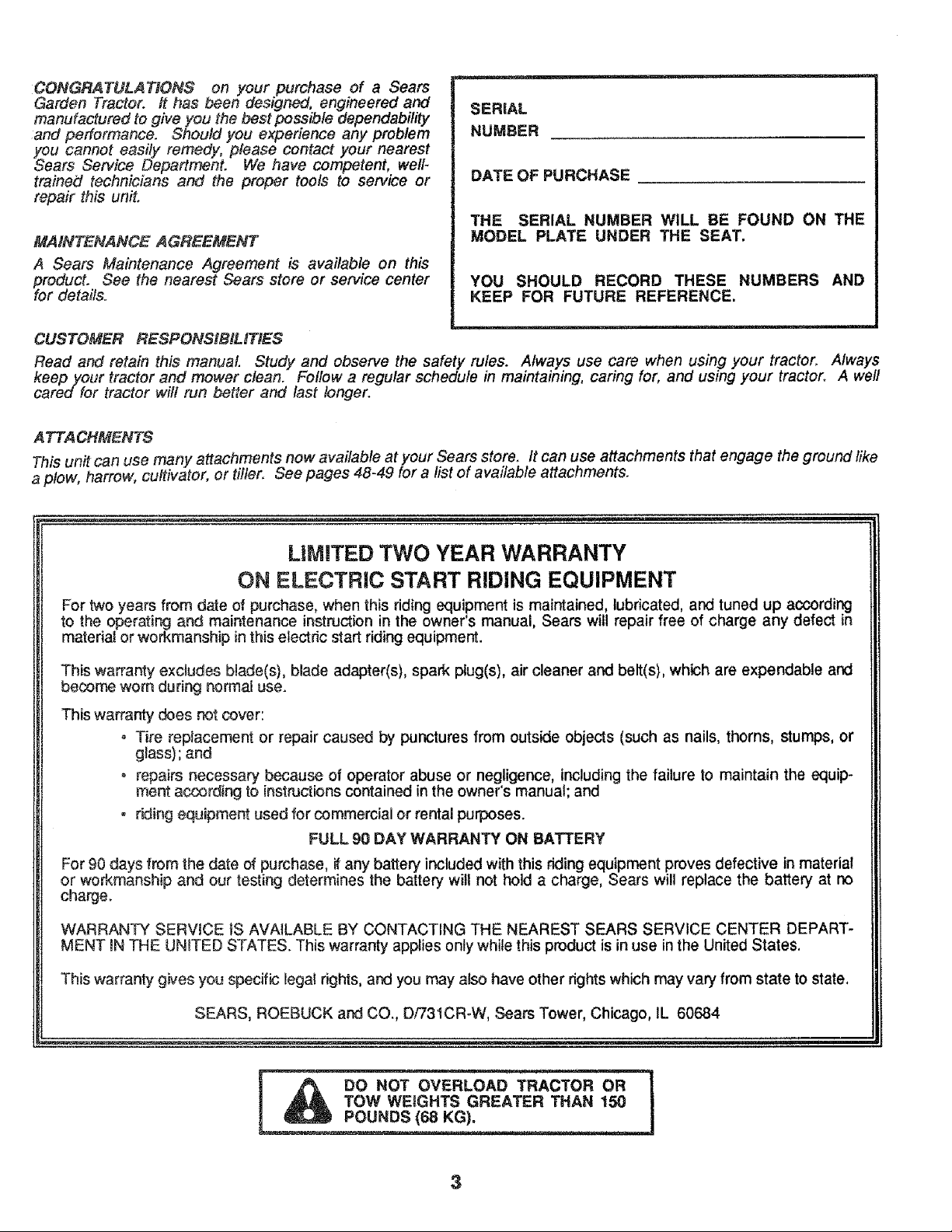
CONGRATULATIONS on your purchase of a Sears
Garden Tractor. It has been designed, engineered and
manufactured to give you the best possible dependabilFty
and performance. Should you experience any problem
YsOUcannot easily remedy, please contact your nearest
ears Service Department. We have competent, well-
trained technicians and the proper tools to service or
repair this unit.
MAINTENANCE AGREEMENT
A Sears Maintenance Agreement is available on this
PforOduCt.See the nearest Sears store or service center
r details.
SERIAL
NUMBER
DATE OF PURCHASE
THE SERIAL NUMBER WiLL BE FOUND ON THE
MODEL PLATE UNDER THE SEAT.
YOU SHOULD RECORD THESE NUMBERS AND
KEEP FOR FUTURE REFERENCE.
CUSTOMER RESPONSIBILITIES
Read and retain this manual Study and observe the safety rules. Always use care when using your tractor. Always
keep your tractor and mower clean. Follow a regular schedule in maintaining, caring for, and using your tractor. A well
cared for tractor will run better and last longer.
A TTA CHMENTS
This unit can use many attachments now available at your Sears store. It can use attachments that engage the ground like
a plow, harrow, cultivator, or tiller. See pages 48-49 for a list of available attachments.
LiMiTED TWO YEAR WARRANTY
ON ELECTRIC START RIDING EQUIPMENT
For two years from date of purchase, when this riding equipment is maintained, lubricated, and tuned up according
to the operating and maintenance instruction in the owner's manual, Sears will repair free of charge any defect in
materiai or workmanship in this electdc start riding equipment.
This warranty excludes blade(s), blade adapter(s), spark plug(s), air cleaner and belt(s), which are expendable and
become worn during normal use.
This warranty does not cover:
= Tire replacement or repair caused by punctures from outside objects (such as nails, thorns, stumps, or
g{ass); and
o repairs necessary because of operator abuse or negligence, including the failure to maintain the equip-
merit according to instn3ctions contained in the owner's manual; and
, riding equipment used for commercial or rental purposes.
FULL 90 DAY WARRANTY ON BATTERY
For 90 days from the date of purchase, if any battery included with this _ing equipment proves defective in material
or workmanship and our testing determines the battery witl not hold a charge, Sears will replace the battery at no
charge.
WARRANTY SERWCE tS AVAILABLE BY CONTACTING THE NEAREST SEARS SERVICE CENTER DEPART-
MENT _NTHE UNITED STATES. This warranty applies only while this product is in use in the United States.
This warranty gives you specific legal rights, and you may also have other rights which may vary from state to state,
SEARS, ROEBUCK and CO., D/731CR_W, Sears Tower, Chicago, IL 60684
3
iNDEX
A
Adjustments:
Brake ..................................... !6
Carburetor ............................. 20
Mower
Front- To-Rear ................... 22
Side- To-Side ..................... 21
Height ............................... 21
Throttle Control Cable ........... 20
Shifter Shaft ........................... 25
Air Cleaner ................................... 17
Air Screen, Engine ....................... 18
Assembly ........ :......................... 5-10
Attachments ............................ 48-49
B
Battery:
Charging ............................ 7, 20
Cleaning ................................ 17
Installation ............................... 8
Levels ...................................... 7
Preparation .............................. 7
Staffing with Weak Battery .... 20
Storage .................................. 25
Terminals ............................... 17
Belt:
Motion Drive
Remora!/Replacement ..... 24
Mower Drive
Installation ........................ !0
Removal ........................... 22
Mower Blade Drive
Rerno val/Replacement .... 23
Blade:
Sharpening ............................ 16
Replacement .......................... 24
Brake Adjustment ......................... 16
C
Carburetor Adjustment ................. 20
Controls, Tractor .......................... 11
Cutting Level, Mower ................... 10
E
Engine:
Air Cleaner ............................. t 7
Air Screen .............................. t8
Cooling fins ............................ 18
0_7ChaRge ............................. 17
Oil Level ................................. 15
Oil Type ................................. 15
Repair Parts ...................... 44-49
Starting .................................. 12
Storage .................................. 25
F
Filter:
Air Cleaner ............................. 1,7
Fuel ........................................ 18
Fuel'.
Type ....................................... t 2
Storage .................................. 25
Fuse ............................................. 2!
H
Hood Removal/Installation ........... 21
L
Leveling Mower Deck ............. 21-22
Lubrication:
Chart ...................................... 19
Tractor Pivot Points ............... 18
M
Maintenance ................................ 15"
Air Cleaner ............................. 17
Foam Pre-cleaner ............. 17
Air Screen, Engine ................. t8
Battery ................................... 17
Blade Sharpening .................. 16
Brake Adjustment .................. !6
Engine Oil .............................. 15
Fuel Filter ............................... 18
Lubrication Chart ................... t9
Spark Plugs ........................... 18
Tire Care .......................... 16, 24
Mower:
Adjustment, Front4o-Rear ..... 22
Adjustment, Side-to-Side ....... 2I
Height .................................... 2 t
Blade Sharpening .................. 16
Blade Replacement ............... 24
Cutting Level .......................... 10
Installation ............................. 10
Operation ............................... !3
Removal ................................ 22
Mowing Tips ................................. 14
Muffler .......................................... 18
Spark Arrestor .................... 2,32
0
Oil:
Cold Weather Conditions ....... 15
Engine ................................... 15
Storage .................................. 25
Operation ................................ 11-14
Operating Your Mower .......... 13
Operating Your Tractor .......... 13
Starting the Engine ................ 12
Stopping Your Tractor ........... 12
Tractor Operation on Hills ...... t4
Options:
Spark Arrestor ................... 2, 32
Attachments 48-49
P
Parking Brake ............................... 11
Parts Bag .................................... 5-6
Pails, Replacement!Repair ..... 30-49
R
Repair and Adjustments .......... 19-25
Blade ...................................... 24
Carburetor ............................. 20
Fuse ....................................... 21
Hood Removal/Installation ..... 2!
Motion Drive Belt
Remova!/Replacement ..... 24
Mower Drive Belt
Installation ........................ 10
Removal ........................... 22
Mower Blade Drive Belt
Removal/Replacement.... 23
Mower Adjustment
Front- to-Rear ................... 22
Side-to-Side ...................... 21
Height ............................... 21
Mower Removal ..................... 23
Tire Care .......................... 16, 24
Repair Parts ............................ 30-49
S
Safety Rules ................................... 2
Seat ................................................ 7
Service Record ............................. 27
Slope Guide Sheet ....................... 51
Spark Plugs .................................. 18
Speed Control Chart .................... 13
Starting the Engine ....................... 12
Steering Wheel ............................... 8
Stopping the Tractor ..................... 12
Storage ......................................... 25
T
Throttle Control Cable
Adjustment ............................. 20
Tires ................................. 16, 24
Trouble Shooting Chart ........... 26-27
Transaxle :
Repair Parts ...................... 42-4.3
Shifter Adjustment ................. 25
W
Warranty ......................................... 3
Wiring Schematic ......................... 29
4
ASSEMBLY
KNOW YOUR TRACTOR
READ THIS OWNER'S MANUAL REFORE OPERATING YOUR GARDEN TRACTOR. If you understand the machine and
its operation, you will achieve efficient and peak performance. While reading the manual, compare the illustrations with your
Garden Tractor to familiarize yourself with the location of various controls and adjustments. Study the operating instructions
and safety precautions thoroughly to insure proper functioning of your Garden Tractor and to prevent injury to yourself and
others. Be sure to pay strict attention to a_lnotes and cautions; they are included for your safety. Save this manual for future
reference.
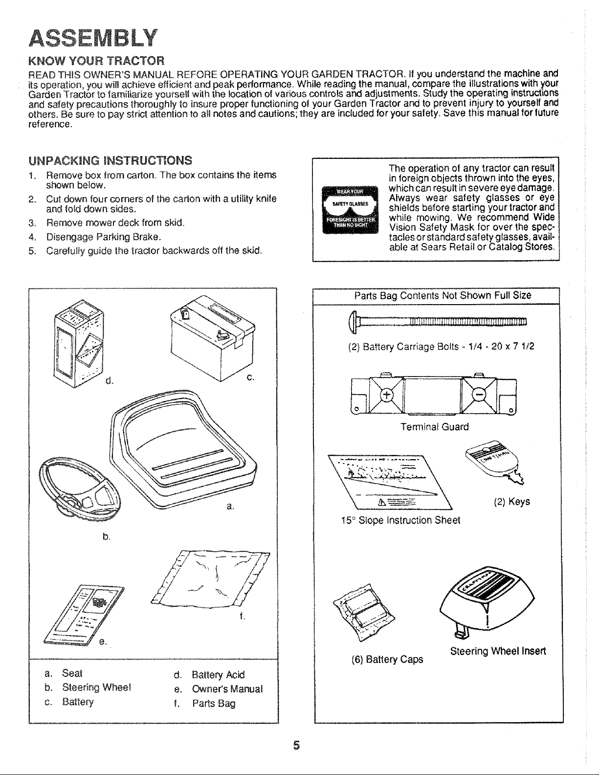
UNPACKING iNSTRUCTIONS
1. Remove box from carton. The box contains the items
shown below.
2. Cut down four corners of the carton with a utility knife
and fold down sides.
3. Remove mower deck from skid.
4. Disengage Parking Brake.
5, Carefu!}y guide the tractor backwards off the skid.
,, ,,,,
The operation of any tractor can result
in foreign objects thrown into the eyes,
which can result in severe eye damage.
Always wear safety glasses or eye
shields before starting your tractor and
while mowing. We recommend Wide
Vision Safety Mask for over the spec-
tacles or standard safety glasses, avail-
able at Sears Retait or Catalog Stores,
b.
a. Seat d, Battery Acid
b, Steering Wheel e. Owner's ManuaJ
c, Battery, f. Parts Bag
Parts Bag Contents Not Shown Full Size
!!!!!!ri[_ti_iiiEf!!!_
(2) Battery Carriage Bolts - 1/4 - 20 x 7 1/2
Terminal Guard
15° Slope Instruction Sheet
(2) Keys
(6) Battery Caps
Steering Wheel Insert
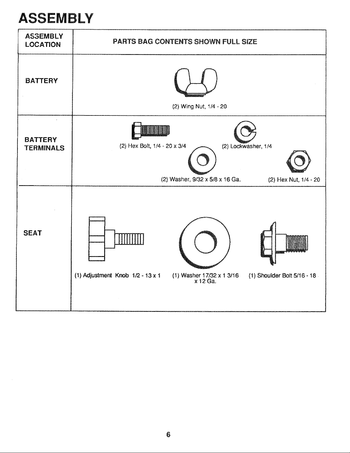
ASSEMBLY
AS3EMBLY
LOCATION
BATTERY
BATTERY
TERMINALS
SEAT
PARTS BAG CONTENTS SHOWN FULL SiZE
(2) Wing Nut, 1/4- 20
(2) Hex Bolt, 1/4 - 20 x 3/4
®
(2) Lockwasher, 1/4
(2) Washer, 9/32 x 5/8 x 16 Ga.
@
(2) Hex Nut, 1/4 - 20
!
- zD
(I) Adjustment Knob I/2 - 13 x I
(1} Washer 17/32 x I 3/'_6
x 12 Ga.
(1) Shoulder Bolt 5/16 - t8
6
To assemble and ao}ust your tractor you will need:
(2) 7/16" Wrenches
(I) 3/4" Wrench
•(1) 9/16" Wrench
(I) !/2" Wrench
(1) 3/4" Socket
Ratchet wrench
Tire Pressure Gauge
Screwdriver
Utility Knife
NOTE: RIGHT HAND (R.H.) AND LEFT HAND (L.H.)
ARE DETERMINED FROM OPERATOR'S POSITION
WHILE SEATED ON THE TRACTOR.
WEAR EYE AND FACE SHIELD.
_[ WASH HANDS OR CLOTHING IMME-
D_ATELY iF ACCIDENTALLY iN CON-
TACT W_TH BATTERY ACID°
DO NOT SMOKE, FUMES FROM
CHARGED BATTERY ACID ARE E×-
PLOSIVE°
NOTE: THIS TRACTOR IS EQUIPPED WITH AN OP-
ERATOR PRESENCE SENSING SW_TCH. ANY AT-
TEMPT BY THE OPERATOR TO LEAVE THE SEAT
WITH THE ENGINE RUNNING AND ATTACHMENT
CLUTCH ENGAGED WILL SHUT OFF THE ENGINE.
t. Prepare Battery
READ INSTRUCTIONS INCLUDED WITH THE BATTERY
VENT CAPS FOUND iN BAG OF PARTS. ALWAYS WEAR
GLOVES, CLOTHING AND GOGGLES TO PROTECT
YOUR HANDS, SKIN AND EYES.
a. Fili and charge battery (before installing). NOTE:
SEE DETklLED iNSTRUCTiONS PACKAGED
WiTH B_,N-E RY VENT CAPS IN BAG OF PARTS.
NOTE: OVERCHARGING WILL SHORTEN BATTERY
LIFE.
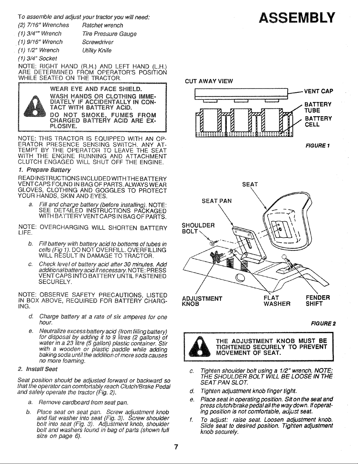
b. Fitl battery with battery acid to bottoms of tubes in
cells (.Fig 1). DO NOT OVERFILL. OVERFILLING
WILL RESULT tN DAMAGE TO TRACTOR.
c. Check le vet of battery acid after 30 minutes. Add
additiona/batteryacidifnecessary. NOTE: PRESS
VENT CAPS iNTO BATTERY UNTIL FASTENED
SECURELY.
CUT AWAY VIEW
I ...........................
SEAT PAN
ASSEMBLY
--- ENT CAP
BATTERY
IBE
BATTERY
CELL
FIGURE I
SEAT
NOTE: OBSERVE SAFETY PRECAUTIONS, LISTED
IN BOX ABOVE, REQUIRED FOR BATTERY CHARG-
INGr
d.
e.
Charge battery at a rate of six amperes for one
hour.
Neutralize excess batterer acid (from tilting battery)
for disposal by adding _t to 9 fitres (2 gallons) of
water in a 23 litre (5 gallon) plastic container. Stir
with a wooden or plastic paddle while adding
baking soda unti! the addition of mere soda causes
no more foaming.
2. Install Seat
Seat position should be adjusted forward or backward so
that the operator can comfortably reach Clutch!Brake Pedal
and safely operate the tractor (Fig. 2).
a.
b.
Remove cardboard from seat pan.
Place seat on seat pan. Screw adjustment knob
and ffat washer into seat (F_g. 3). Screw shoulder
bolt into seat (Fig. 3). Adjustment knob, shoulder
bolt and washers found in bag of parts (shown full
size on page 6)_
ADJUSTMENT FLAT FENDER
KNOB WASHER SHIFT
FIGURE 2
_ TIGHTENED SECURELY TO PREVENT
MOVEmeNTSEA',"
c. Tighten shoulder bolt using a 1/2" wrench. NOTE:
THE SHOULDER BOLT WILL BE LOOSE tN THE
SEAT PAN SLOT.
d. Tighten adjustment knob finger tight.
e. Place seat in operating position. Sit on the seat and
press clutchforake pedal all the way down. ff operat-
ing position is not comfortable, adjust seat.
f. To adjust: raise seat. Loosen adjustment knob.
Slide seat to desired position. Tighten adjustment
knob securely.
A Y
STEERING WHEEL CAP
HEX LOCK NUT
2 , '1/4" DIA. WASHER
_- STEER|NG
____Jr-__-3,_--_,¢,/ / WHEEL
FIGURE 3
AIR
INTAKE
DUCT
"\
HOOD
GRILL
FIGURE 4
BATTERY
COMPARTMENT
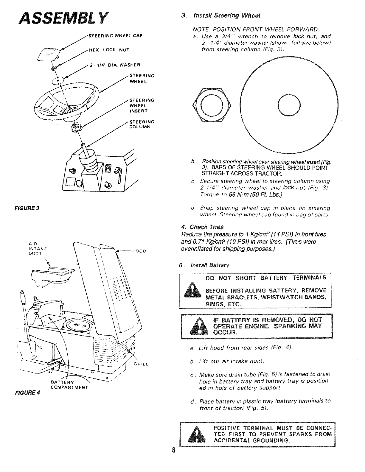
3. Install Steering Wheel
NOTE: POSITION FRONT WHEEL FORWARD.
a, Use a 3/4" wrench to remove lock nut, and
2 ,. 1/4" diameter washer (shown full size below)
from steering column (Fig. 3).
b. Position steering wheel over steering wheel insert (Fig,
3). BARS OF STEERING WHEEL SHOULD POINT
STRAIGHT ACROSS TRACTOR.
c. Secure steering wheel to steertng column using
2- 1/4"' diameter washer and lock nut (Fig, 3).
Torque to 68 N-m (50 Ft. Lbs.)
d. Snap steering wheel cap in place on steering
wheel, Steering wheel cap found in bag of parts,
4. Check Tires
Reduce tire pressure to 1Kg/cm _ (14 PSi) in front tires
and 0.71 Kg/cm 2 (10 PSi) in reartires. (Tires were
overinflated for shipping purposes.)
5. Install Battery
DO NOT SHORT BATTERY TERMINALS
BEFORE INSTALLING BATTERY, REMOVE
METAL BRACLETS, WRISTWATCH BANDS,
RINGS, ETC.
a. Lift hood from rear sides (Fig. 4).
b. Lift out air intake duct.
c MaRe sure drain tube (Fig. 5) is fastened to drain
hole in battery tray and battery tray is position
ed in hole of battery support.
d. Place battery in plastic tray (battery terminals to
front of tractor) (Fig. 5).
,_ POSITIVE TERMINAL MUST BE CONNEC- 1
,_ TED FIRST TO PREVENT SPARKS FROM
_ENTAL GROUNDmNG.
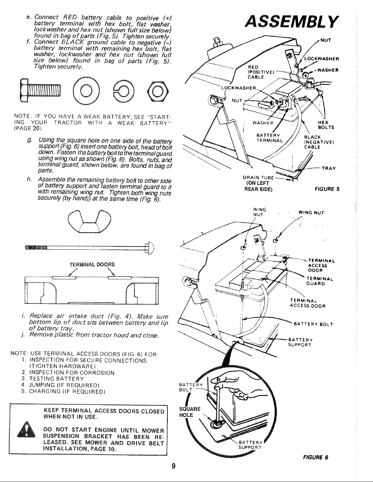
e. Connect RED battery cable to positive (+)
battery terminal with hex bolt, flat vcasher,
Iockwasher and hex nut (shown full size below)
found in bag of parts (Fig. 5). Tighten securely,
f, Connect BLACK ground cable to negative (-)
battery terminal with remaining hex bolt, flat
washer, lockwasher and hex nut (shown full
size below) found in bag of parts (Fig, 5).
Tighten securely.
NOTE: IF YOU HAVE AWEAK BATTERY, SEE "START-
ING YOUR TRACTOR WITH A WEAK BATTERY'"
(PAGE 20t.
g. Using the square hole on one side of the battery
support (Fig. 6) insert one battery bolt, head of bolt
down. Fasten the battery bolt to the t erminat guard
using wing nut as shown (Fig. 6). Bolts, nuts, and
terminal guard, shown below, are found in bag of
parts.
h. .Assemble the remaining battery bolt to other side
of battery support and fasten terminal guard to it
with remaining wing nut. Tighten both wing nuts
securely (by hand)) at the same time (Fig. 6).
TERMINAL DOORS
L Replace air intake duct (Fig. 4). Make sure
bottom lip of d#ct sits between battery and lip
of battery tray,
j. Remove plastic from tractor hood and close.
NOTE:
1.
USE TERMINAL ACCESS DOORS (FIG. 6) FOR:
INSPECTION FOR SECURE CONNECTIONS
(TIGHTEN HARDWARE)
2. _NSPECTtON FOR CORROSION
3. TESTING BATTERY
4. JUMPING (IF REQUIRED)
5. CHARGING (IF REQUIRED)
KEEP TERMINAL ACCESS DOORS CLOSED
WHEN NOT iN USE.
DO NOT START ENGINE UNTIL MOWER
SUSPENSION BRACKET HAS BEEN RE-
LEASED, .SEE MOWER AND DRIVE BELT
{LNSTALLAT_ON, PAGE 10,
BATTERY
BOLT
SQ_UARE
HOLE
A SSEIVIBL Y
/ NUT
/
-WASHER
HEX
BOLTS
BLACK
(NEGATIVEI
CABLE
DRAIN
(ON LEFT
REAR SIDE)
FIGURE 5
ERM_NAL
ACCESS
DOOR
TERMINAL
GUARD
\
} TERMINAL
ACCE_ DOOR
Y _OLT
SUPPORT
FIGURE 6
Y
FIGURE 7
/
ENGINE
- PULLEY
/
ATTACHMENTCLUTCH
SWITCH
POSITION)
HEIGHT ADJUSTMENT
KNOB
RGURE 9
REAR HINGE
_/ LiFT LEVER
PLUNGER
LIFT LEVER
LOWER
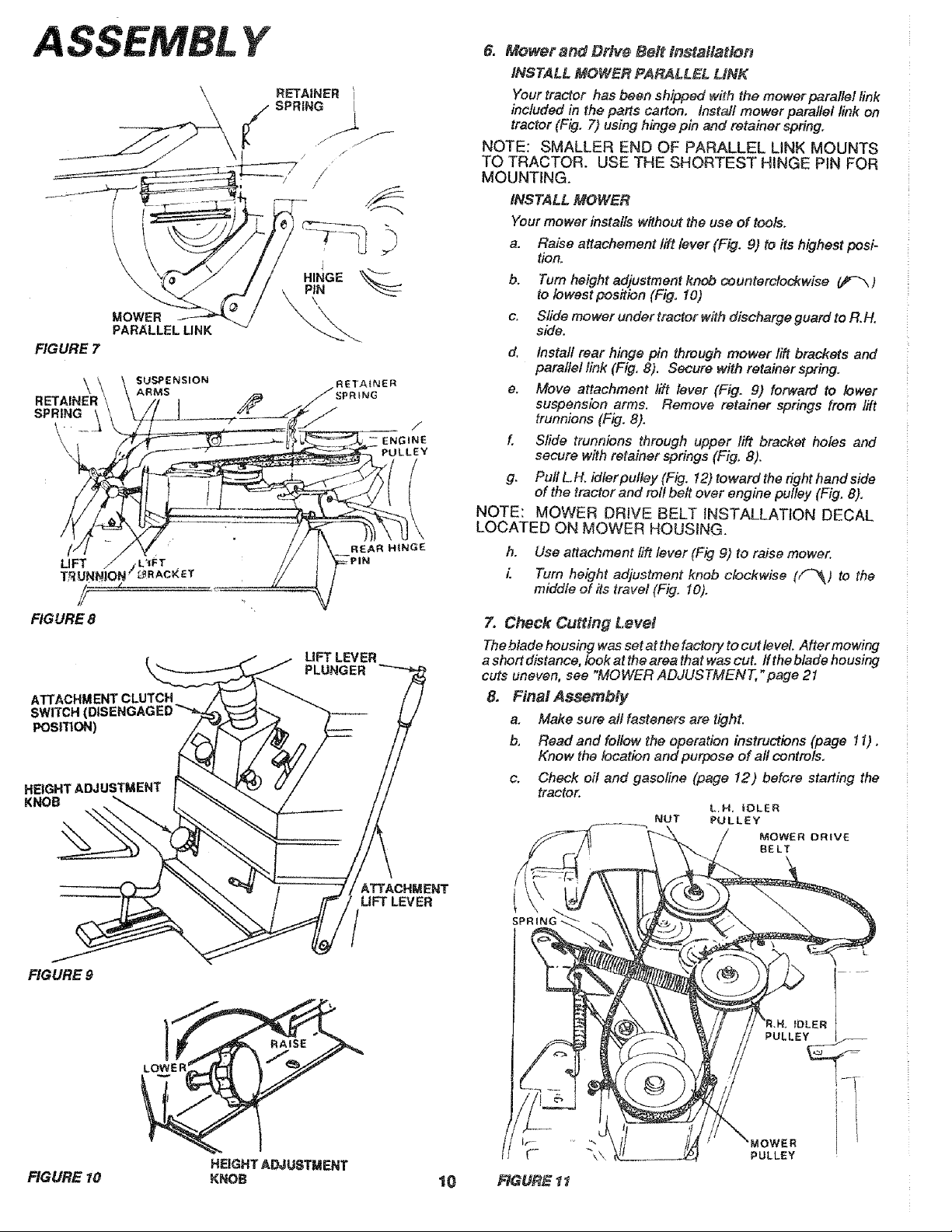
6. Mower and Drive Bell tnstal/at_n
iNSTALL MOWER PARALLEL LiNK
Yourtractor has been shipped with the mower parallel link
includedin the parts carton. Install mower parallel link on
tractor (Fig. 7) usinghinge pin and retainerspring.
NOTE: SMALLER END OF PARALLEL LiNK MOUNTS
TO TRACTOR. USE THE SHORTEST HINGE PIN FOR
MOUNTING.
INSTALL MOWER
Your mower installs without the use of tools,
a. Raise attachement 1_ lever (Fig. 9) to its highest posi-
tion.
b. Turn height adjustment knob counterclockwise _ )
to lowest pos#ion (Fig. 10)
c, Slide mower under tractor with discharge guard to R.FL
side.
d. Install rear hinge pin through mower lift brackets and
parallel link (Fig, 8). Secure with retainer spring,
e, Move attachment lift lever (Fig. 9) forward to lower
suspension arms. Remove retainer springs from lift
trunnions (Fig, 8).
f, Slide trunnions through upper lift bracket holes and
secure with retainer springs (Fig, 8).
g. Pull L,H. idlerpulley (Fig. 12) toward the right hand side
of the tractor and roll be# over engine pulley (Fig. 8),
NOTE: MOWER DRIVE BELT iNSTALLATiON DECAL
LOCATED ON MOWER HOUSING.
h, Use attachment tilt lever (Fig 9) to raise mower.
L Turn height adjustment knob clockwise (f-_) to the
middle of its travel (Fig, 10),
7. Check Cutting Lever
The blade housing was set at the factory to cut leveL After mowing
a short distance, look at the area that was cut. ff the blade housing
cuts uneven, see "MOWER ADJUSTMENT, "page 21
8. Final Assembly
a, Make sure all fasteners are tight.
b, Read and follow the operation instructions (page 11).
Know the location and purpose of all controls.
c. Check oil and gasoline (page 12) before staffing the
tractor,
L.H, iDLER
NUT PULLEY
MOWER DRIVE
BELT
PULLEY
HEIGHT ADJUSTMENT
FIGURE 10 KNOB 10 RGURE 1"1
OPERATION
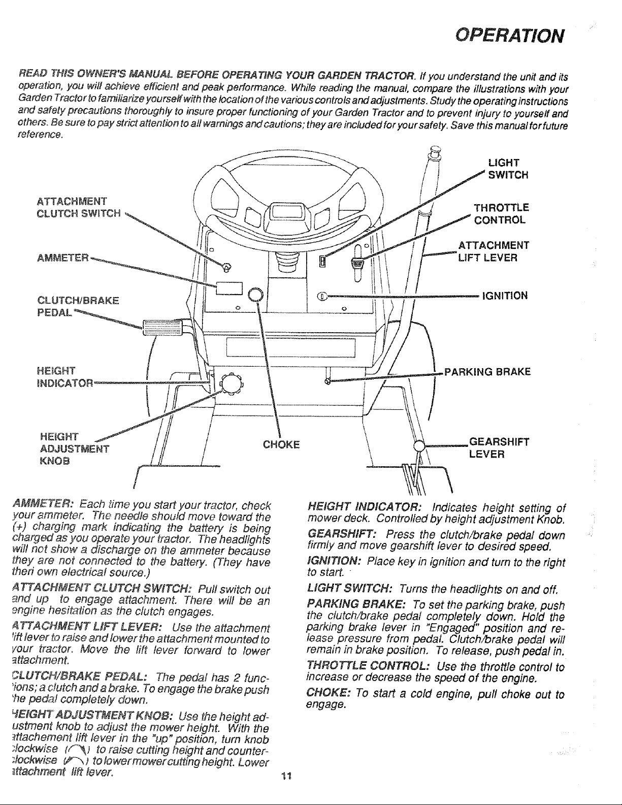
READ THIS OWNER'S MANUAL BEFORE OPERATING YOUR GARDEN TRACTOR. ff you understand the unit and its
operation, you will achieve efficient and peak performance. While reading the manual, compare the #lustrations with your
Garden Tractor to familiarize yourself with the location of the various controls and adjustments, Study the operating instructions
and safety precautions thoroughly to insure proper functioning of your Garden Tractor and to prevent injury to yourseff and
others. Be sure to pay strict attention to all warnings and cautions ; they are included for your safety. Save this manual for future
reference.
LIGHT
SWITCH
ATTACHMENT
CLUTCH SWITCH
THROTTLE
CONTROL
_MENT
LEVER
G_ IGNITION
O
:_ARKING BRAKE
HEIGHT CHOKE GEARSHIFT
ADJUSTMENT LEVER
KNOB
AMMETER: Each time you start your tractor, check
your _mmeter. The needle should move toward the
(+) charging mark indicating the battery is being
charged as you operate your tractor. The headlights
will not show a discharge on the ammeter because
they are not connected to the battery. (They have
theri owr_ electrical source.)
ATTACHMENT CLUTCH SWITCH: Pull switch out
_nd up to engage attachment. There will be an
_ngine hesitation as the clutch engages.
ATTACHMENT LHFT LEVER: Use the attachment
_iftlever to raise and lower the attachment mounted to
Four tractor. Move the lift lever fot_ard to lower
_ttachment.
CLUTCH/BRAKE PEDAL: The pedal has 2 func-
'ions; a clutch and a brake. To engage the brake push
'he peda! completely down.
_EIGHT ADJUSTMENT KNOB: Use the height ed-
ustment knob to adjust the mower height. With the
_ttacheme_nt lift lever in the "up" position, turn knob
:lockwise (_) to raise cutting height and counter-
:lockwi_e _*-"_ ) to lower mower cutting height. Lower
_tfachment lift tevero
tl
HEIGHT INDICATOR: Indicates height setting of
mower deck. Controlled by height adjustment Knob.
GEARSHIFT: Press the clutch/brake pedal down
firmly and move gearshift lever to desired speed,
IGNITION: Place key in ignition and turn to the right
to start.
LIGHT SWITCH: Turns the headlights on and off.
PARKING BRAKE: To set the parking brake, push
the clutch/brake pedal completely down. Hold the
parking brake lever in "Engaged" position and re-
lease pressure from pedal. Clutch/brake pedal will
remain in brake position, To release, push pedal in.
THROTTLE CONTROL: Use the throttle control to
increase or decrease the speed of the engine.
CHOKE: To start a cold engine, pull choke out to
engage.
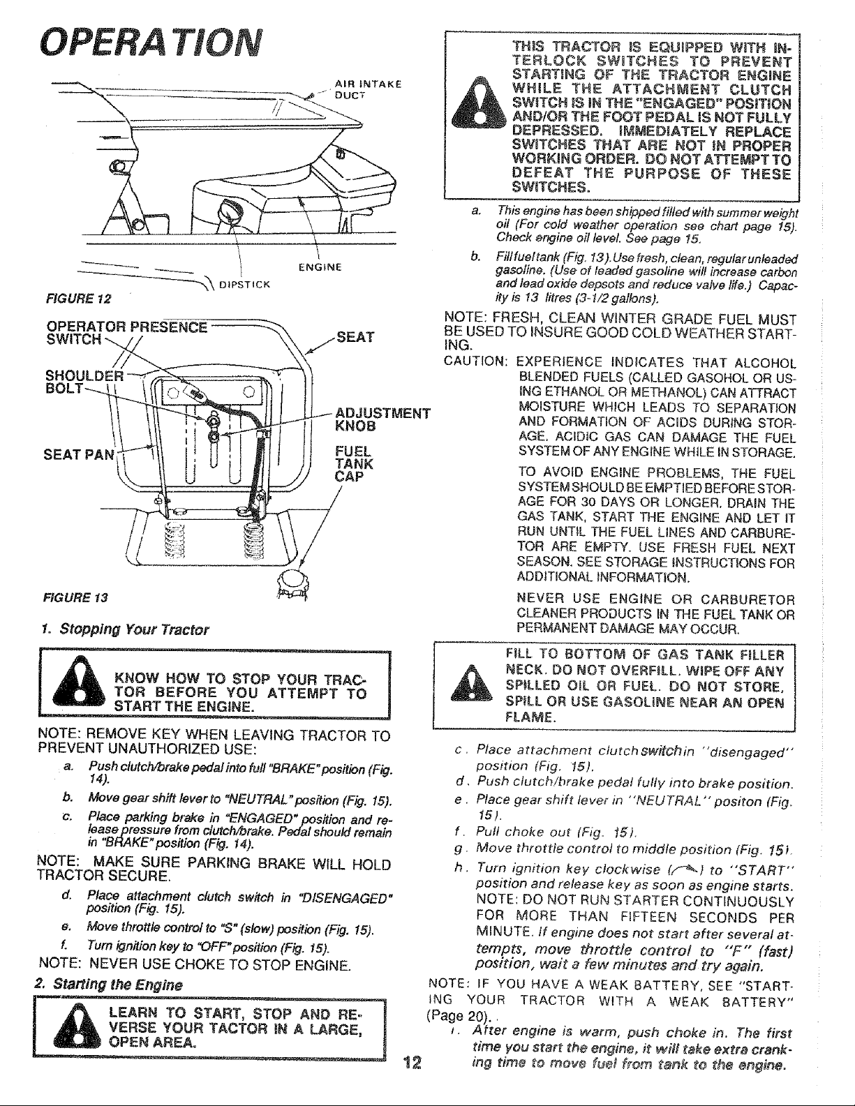
OPERA T/ON
•AIR _NTAKE
DUCT
'_'_ DIPSTICK
FIGURE 12
OPERATOR PRESENCE
ENGINE
SEAT PAN
JSTMENT
KNOB
FUEL
TANK
CAP
FIGURE 13
1. Stopping Your Tractor
KNOW HOW TO STOP YOUR TRAC-
TOR BEFORE YOU ATTEMPT TO
START THE ENGINE.
NOTE: REMOVE KEY WHEN LEAVING TRACTOR TO
PREVENT UNAUTHORIZED USE:
a. Push clutch!brake pedal into full "BRAKE"position (Fig.
14).
b. M°ve gear shift lever to "NEUTRAL"position (Fig. 15).
c. Place parking brake in "ENGAGED" position and re-
lease pressure from clutchf#rake. Pedal should remain
in "BRAKE" position (Fig. 14).
NOTE: MAKE SURE PARKING BRAKE WILL HOLD
TRACTOR SECURE,
d. Piece attachment clutch switch in "DISENGAGED"
position (Fig. i5).
e. Move throttlecontrol to '_S"(slow) position (Fig. 15).
f. Turnignition key to "OFF"position (Fig. 15).
NOTE: NEVER USE CHOKE TO STOP ENGINE,
2. Starting the Engine
LEARN TO S_
VERSE YOUR TACTOR |N A LARGE, I
THIS TRACTOR |S EOUnPPED WITH IN-
TERLOCK SWmTCHES TO PREVENT
STARTING OF THE TRACTOR ENGINE
WHILE THE ATTACHMENT CLUTCH
SWITCH IS JNTHE "ENGAGED" POSiTiON
AND/OR THE FOOT PEDAL iS NOT FULLY
DEPRESSED. iMMEDIATELY REPLACE
SWITCHES THAT ARE NOT tN PROPER
WORKING ORDER. DO NOT ATTEMPTTO
DEFEAT THE PURPOSE OF THESE
SW_TCHES.
a, This engine has been shipped filled with summer weight
oil (For cold weather operation see chart page 15).
Check engine oil level. See page 15,
b. Filtfueltank (Fig, 13),Usefresh, ctean, regularunleaded
gasoline. (Use of leaded gasoline wilt increase carbon
and lead oxide depsots and reduce valve life.) Capac-
ity is 13 litres (3-1/2 galfons).
NOTE: FRESH, CLEAN WINTER GRADE FUEL MUST
BE USED TO iNSURE GOOD COLD WEATHER START-
ING.
CAUTION: EXPERIENCE INDICATES THAT ALCOHOL
BLENDED FUELS (CALLED GASOHOL OR US-
iNG ETHANOL OR METHANOL) CAN ATTRACT
MOISTURE WHICH LEADS TO SEPARATION
AND FORMATION OF ACIDS DURING STOR-
AGE, ACIDIC GAS CAN DAMAGE THE FUEL
SYSTEM OF ANY ENGINE WHILE IN STORAGE.
TO AVOID ENGINE PROBLEMS, THE FUEL
SYSTEM SHOULD BE EMPTIED BEFORE STOR-
AGE FOR 30 DAYS OR LONGER. DRAIN THE
GAS TANK, START THE ENGINE AND LET iT
RUN UNTIL THE FUEL LINES AND CARBURE-
TOR ARE EMPTY. USE FRESH FUEL NEXT
SEASON, SEE STORAGE INSTRUCTIONS FOR
ADDITIONAL _NFORMATtON.
NEVER USE ENGINE OR CARBURETOR
CLEANER PRODUCTSIN THEFUELTANK OR
PERMANENT DAMAGE MAYOCCUR.
FiLL TO BOTTOM OF GAS TANK F&LER
NECK. DO NOT OVERF&L. WiPE OFF ANY
SPILLED OiL OR FUEL. DO NOT STORE,
SPILL OR USE GASOLINE NEAR AN OPEN
FLAME.
t2
c, Place attachment ctutch ewitchin "'disengaged'"
position (Fig, 15).
d. Push clutch!brake pedal fully into brake position.
e. Place gear shift lever in "NEUTRAL'" positon (Fig,
15),
f, Pull choke out (Fig. _r).
g, Move throttie centre! to middle position (Fig. 15L
h, Turn ignition key clockwise (f_) to "START"
position end release key as soon as engine starts.
NOTE: DO NOT RUN STARTER CONTINUOUSLY
FOR MORE THAN FIFTEEN SECONDS PER
MINUTE. If engine does not start after several at-
tempts, move throttle control to "F" (fast)
position, wait a few minutes and try again.
NOTE: IF YOU HAVE A WEAK BATTERY, SEE "START-
ING YOUR TRACTOR WITH A WEAK BATTERY"
(Page 20).,
f. After engine is warm, push choke in. The first
time you start the engine, Jt wifi take extra crank-
ing time to move iue_ from tank to the engine.
NOTE: ALLOW ENGINE TO WARM UP FOR A
FEW MINUTES BEFORE ENGAGING CLUTCH OF
TRACTOR OR ATTACHMENT-
When restarting a warm engine, move throttle
control midway between "'S" (stow) and
"F" (fast) positions. Choke may not have
7o be used.
GMPORTANT: BEFORE DRIVING THE TRACTOR,]
_NSTALL MOWER OR REMOVE
JMOWER PARALLEL UNK.
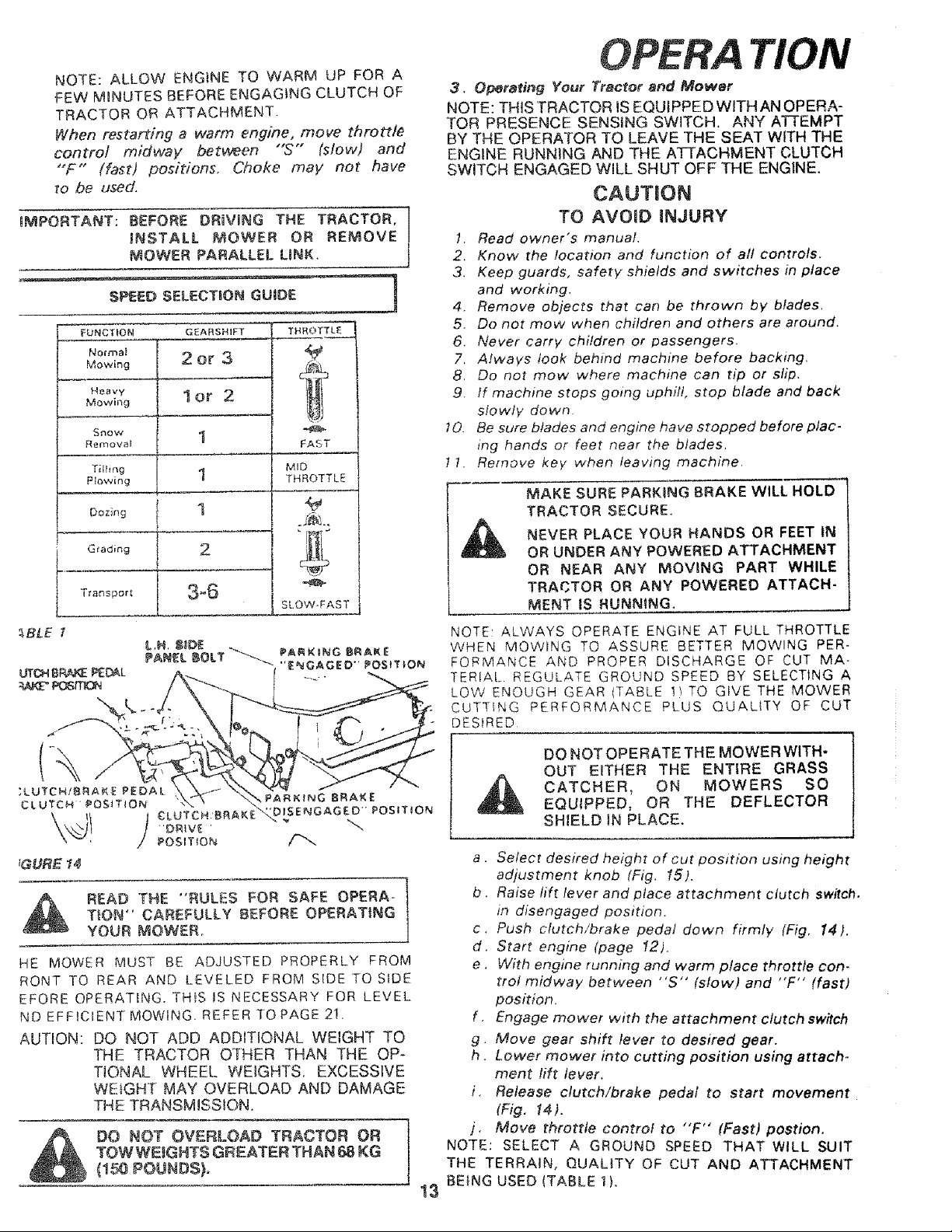
FUNCTIONMowingMOWingNOl.matHeavy21GEARSHIFTorOr32 I THROT_"_'3 L £
Sf'lOW 1
Removal
Tilling
P_o',,ving 1
Dozing 1
2Grading
Transport 3°6
FAST
MID
THROTTLE
SLOW-FAST
_BLE
READ THE "RULES FOR SAFE OPERA-
T}ON" CAREFULLY BEFORE OPERATING
YOUR MOWER
HE MOWER MUST BE ADJUSTED PROPERLY FROM
RONT TO REAR AND LEVELED FROM SIDE TO SIDE
EFORE OPERATING. TH_S tS NECESSARY FOR LEVEL
ND EFFICIENT MOWING. REFERTOPAGE 2!.
AUTION: DO NOT ADD ADDITIONAL WEIGHT TO
THE TRACTOR OTHER THAN THE OP-
TIONAL WHEEl.. WEIGHTS. EXCESSIVE
WEIGHT MAY OVERLOAD AND DAMAGE
THE TRANSMISSION.
DO NOT OVERLOAD TRACTOR OR
TOWWEtGHT$ GREATER THAN 68 KG
_150 POUNDS),
OPERA TION
3. O_rating Your Tractor and Mower
NOTE: THiS TRACTOR IS EQUIPPED WITH AN OPERA-
TOR PRESENCE SENSING SWITCH. ANY ATTEMPT
BY THE OPERATOR TO LEAVE THE SEAT WITH THE
ENGINE RUNNING AND THE ATTACHMENT CLUTCH
SWITCH ENGAGED WiLL SHUT OFF THE ENGINE.
CAUTION
TO AVOID INJURY
t. Read owner's manual.
2. Know the location and function of all controls.
3. Keep guards, safety shields and switches in place
and working.
4. Remove objects that can be thrown by blades.
5 Do not mow when children and others are around.
6. Never carry children or passengers.
7. Always look behind machine before backing.
8. Do not mow where machine can tip or slip.
9 If machine stops going uphill, stop blade and back
slowly down.
10. Be sure blades and engine have stopped before plac-
ing hands or feet near the blades,
I !. Remove key when leaving machine.
MAKE SURE PARKING BRAKE WILL HOLD
TRACTOR SECURE.
NEVER PLACE YOUR HANDS OR FEET tN
OR UNDER ANY POWERED ATTACHMENT
OR NEAR ANY MOVING PART WHILE
TRACTOR OR ANY POWERED ATTACH-
MENT IS RUNNING,
NOTE: ALWAYS OPERATE ENGINE AT FULL THROTTLE
WHEN MOWING TO ASSURE BETTER MOWING PER-
FQRMANCE AND PROPER DISCHARGE OF CUT MA-
TERIAL REGULATE GROUND SPEED BY SELECTING A
LOW ENOUGH GEAR (TABLE 1t TO GiVE THE MOWER
CUTTING PERFORMANCE PLUS QUAL{TY OF CUT
DESIRED
DO NOTOPERATETHE MOWER WITH-
OUT EITHER THE ENTIRE GRASS
CATCHER, ON MOWERS SO
EQUIPPED, OR THE DEFLECTOR
SHIELD iN PLACE,
a. Select desired height of cut position using height
adjustment knob (Fig. 15).
b. Raise lift lever and place attachment clutch sw#ch.
in disengaged position.
c. Push clutch/brake pedal down firmly (Fig. 14).
d. Start engine (page 12).
e. With engine running and warm place throttle con.
trot midway between "S" (slow) and "F'" (fast)
position.
f . Engage mower with the attachment clutch switch
g. Move gear shift lever to desired gear.
h. Lower mower into cutting position using attach-
ment lift lever.
i. Release clutch/brake pedal to start movement
(Fig. 14).
j. Move throttle control to "'F'" (Fast) postion.
NOTE: SELECT A GROUND SPEED THAT WILL SUIT
THE TERRAIN, QUALITY OF CUT AND ATTACHMENT
BEING USED (TABLE 1}.
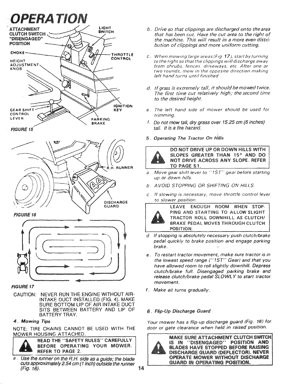
HEIGHT
KNOB
b_
Drive so that clippings are discharged onto the area
that has been cut, Have the cut area to the r_qht of
the machine. This will result in a more even distri-
bution of clippings and more uniform cutting,
e,
When mo wing large areas (Fig 17), start b y turning
to the right so that the chpptngs wH/ discharge away
from shrubs, fences driveways, etc, After one or
two rounds, mow in the opposite dzrection making
left hand turns until f/nfshed
GEAR
CONTROL
LEVER
FIGURE 15
YRUNNER
DISCHARGE
GUARD
FIGURE 16
FIGURE 17
CAUTION: NEVER RUN THE ENGINE WITHOUT AiR-
INTAKE DUCT INSTALLED (FIG. 4). MAKE
SURE BOTTOM LIP OF AIR INTAKE DUCT
SITS BETWEEN BATTERY AND LIP OF
BATTERY TRAY,
4, Mowing Tips
NOTE: TIRE CHAINS CANNOT BE USED WITH THE
MOWER HOUSING ATTACHED,
I & READ THE "'SAFETY RULES" CAREFULLY
BEFORE OPERATING YOUR MOWER.
REFER TO PAGE 2.
a Use the runner on the R,H. side as a guide; the blade
cuts approximately2,54 cm (1 inch) outside the runner
(Fig. 16).
d. lf grass is extremely tall, it should be mowed twice,
The first time cut relatively high," the second time
to the desired height,
e. The left hand side of mower should be used for
trimming,
f. Do not mow tall, dry grass over 15.25 cm (6 inches)
tall. tt is a fire hazard.
5. Operating The Tractor On HilfS
L _ DO NOT DRtVE UP OR DOWN H_LLS WiTH
SLOPES GREATER THAN 15 ° AND DO
NOT DRIVE ACROSS ANY SLOPE. REFER
TO PAGE 5!.
a. Move gear shift lever to "' 1ST" gear before starting
up or down hilfs.
b, AVOID STOPPING OR SHIFTING ON HILLS,
c, If slowing is necessary, move throttle control lever
to slower position.
LEAVE ENOUGH ROOM WHEN STOP-
PiNG AND STARTING TO ALLOW SLIGHT
TRACTOR ROLL DOWNHaLL AS CLUTCH/
8RAKE PEDAL MOVES THROUGH CLUTCH
POSITION,
d. If stopping is absolutely necessary push clutch/brake
pedal quickly to brake position and engage parking
brake.
e. To restart tractor movement, make sure tractor is in
the lowest speed range ("1ST'" Gear) and that you
have allowed room to roll slightly downhill. Depress
clutch/brake full. Disengaged parking brake and
release clutch/brake pedal SLOWLY to start tractor
movement.
f. Make all turns gradua#V.
t4
6, Rip-Up Discharge Guard
Your mower has a flip-up discharge guard (Fig. t6) for
door or gate clearance when held in raised position.
MAKE SURE ATTACHMENT CLUTCH SWITCH]
_ 18 IN °D_SENGAGED" POSmTaON AND |
8LADES NAVE STOPPED BEFORE RAiSiNG |
DISCHARGE GUARD _DEFLECTORL NEVER |
OPERATE P_OWER WITHOUT #iSCHARGE |
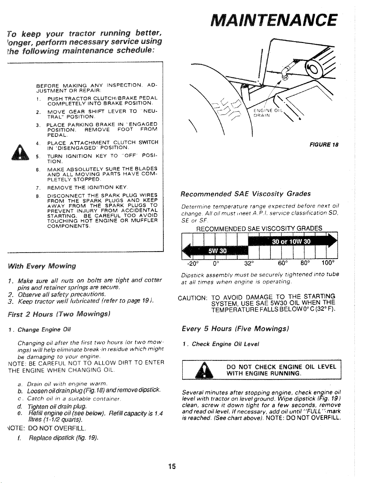
To keep your tractor running better,
ronger, perform necessary service using
_he following maintenance schedule:
BEFORE MAKING ANY INSPECTION, AD-
JUSTMENT OR REPAJR:
1, PUSH TRACTOR CLUTCHtBRAKE PEDAL
COMPLETELY INTO BRAKE POSITION,
2. MOVE GEAR SHIFT LEVER TO "NEU-
TRAL" POSITION.
3, PLACE PARKING 8RAKE IN "ENGAGED
POSITION, REMOVE FOOT FROM
PEDAL.
4_ PLACE ATTACHMENT CLUTCH SWITCH
IN 'DISENGAGED _ POSITION,
5. TURN IGNiTiON KEY TO 'OFF" POSI*
TION,
6. MAKE ABSOLUTELY SURE THE BLADES
AND ALL MOVING PARTS HAVE COM-
PLETELY STOPPED.
7. REMOVE THE IGNITION KEY.
8. DISCONNECT THE SPARK PLUG WIRES
FROM THE SPARK PLUGS AND KEEP
AWAY FROM THE SPARK PLUGS TO
PREVENT iNJURY FROM ACCIDENTAL
STARTING, BE CAREFUL TOO AVOID
TOUCHING HOT ENGINE OR MUFFLER
COMPONENTS.
MAIN
\
\
FIGURE 18
Recommended SAE Viscosity Grades
Determine temperature range expected before next oil
change. At/ oil must meet A. P 1. service classification SD,
SE or SF,
RECOMMENDED SAE VISCOSITY GRADES
With Every Mowing
t. Make sure all nuts on bolts are tight and cotter
pins and retainer springs are secure.
2. Observe all safety precautions.
3. Keep tractor we//lubricated (refer to page 19).
First 2 Hours (Two Mowings}
1. Change Engine Oi[
Changing oil after the first two hours (or two mow-
ings) wifl help eliminate break-in residue which might
be damaging to your engine.
NOTE: BE CAREFUL NOT TO ALLOW DIRT TO ENTER
THE ENGINE WHEN CHANGING OtL,
a. Drain oil with engine warm,
b. Loosen oil drain plug (Fig. 18) and remove dipstick.
c. Catch oil in a suitable container,
d. Tighten oil drain plug.
e. Refill engine oil (see below). Refill capacity is 1.4
litres (t-I/2 quarts),
gOTE: DO NOT OVERFILL,
L Replace dipstick (fig. 19).
-20 ° 0 ° 32 ° 60 ° 80 ° 100 °
Dipstick assembly must be securely t_ghtened into tube
at all times when engine is operating.
CAUTION: TO AVOID DAMAGE TO THE STARTING
SYSTEM, USE SAE 5W30 OIL WHEN THE
TEMPERATURE FALLS BELOW0° C (32° F).
Every 5 Hours (Five Mowings)
1. Check Engine Oil Level
,_ DO NOT CHECK ENGINE OIL LEVELWITH ENGINE RUNNING. , ..... i
Several minutes after stopping engine, check engine oil
level with tractor on level ground. Wipe dipstick (Fig. 19 )
clean, screw it down tight for a few seconds, remove
and read oil level. If necessary, add oil until "FULL "" mark
is reached, (See chart above), NOTE: DO NOT OVERFILL.
15
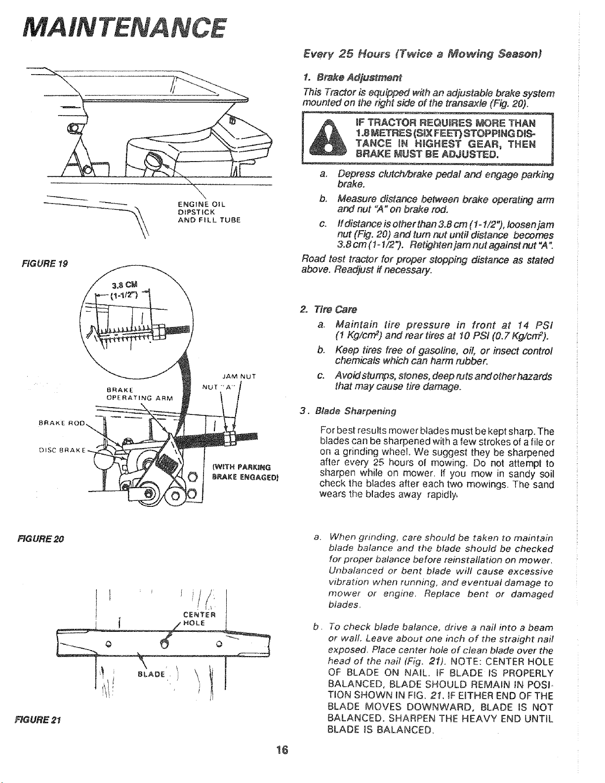
FIGURE 19
8RAKE
OPERATING ARM
BRAKE
D_SC
NCE
Every 25 Hours (T_#ce a Mow#ng SeasonJ
f. Bmk_ Adjustmsnt
This Tractor is equipped with an adjustable brake system
mounted on the right side of the transaxte (Fig. 20).
,_ !_T}STOPPING DUS- !
T_ItGHEST GEAR, THEN
a, Depress clutch/brake pedal and engage parking
brake.
b, Measure distance between brake operating arm
and nut "A" on brake rod.
c. If distance is other than 3.8 cm (1 _!/2 "), lossen jam
nut (Fig. 20) and rum nut until distance becomes
& 8 cm ( ! _1/2 "), Rstighten jam nut against nut "A".
Road test tractor for proper stopping distance as stated
above. Readjust if necessary.
2. Tim Cars
a. Maintain tire pressure in front at 14 PSi
(1 Kg/crrF) and rear tires at 10 PSi (0.7 Kg/cn_).
b. Keep tires free of gasoline, oil, or insect control
chemicals which can harm rubber.
c. Avoid stumps, stones, deep ruts and other hazards
that may cause tire damage.
3. Blade Sharpening
For best results mower blades must be kept sharp. The
btades can be sharpened with a few strokes of a file or
on a grinding wheel. We suggest they be sharpened
after every 25 hours o! mowing. Do not attempt to
sharpen while on mower, tf you mow in sandy soil
check the blades after each two redwings. The sand
wears the blades away rapidly,
FIGURE 20
a,
b,
When grinding, care should be taken to maintain
blade balance and the blade should be checked
for proper balance before reinstailation on mower.
Unbalanced or bent blade will cause excessive
vibration when running, and eventual damage to
mower or engine, Replace ben_ or damaged
blades,
To check blade balance, drive a nail into a beam
or wall. Leave about one inch of the straight nail
exposed, Place center hole of clean blade over the
head of the nail (Fig. 2f), NOTE: CENTER HOLE
OF BLADE ON NAIL. IF BLADE tS PROPERLY
BALANCED, BLADE SHOULD REMAIN IN POSI-
TION SHOWN IN FIG. 2t, IF EITHER END OF THE
BLADE MOVES DOWNWARD, BLADE IS NOT
BALANCED. SHARPEN THE HEAVY END UNTIL
BLADE _S BALANCED.
t8

Every 50 Hours (Once. Mo_ing So,son)
(Operating in dusty conditions may require more frequent
servicing. )
1, Check Bat:tery
e .
NOTE:
a, Battery acid level in each battery cell
should be even with bottoms of tubes in ceils {Fig,
221. Add ONLY distilled water if necessary.
NOTE: DO NOT OVERFILL.
b. Keep battery and terminals clean,
e. Keep battery bolts tight.
d. Keep vent caps tight and small vent holes in caps
open.
Recharge at 6 amperes for ! hour if necessary,
OVERCHARGING WILL SHORTEN BATTERY LIFE.
INTENANCE
CUT AWAY VIEW
VENT CAP
BATTERY
TUBE
BATTERY
CELL
FIGURE 22
2. Clean Battery and Terminals
Corrosion and dirt on the battery and terminals cause the
battery to "leak" power.
LEAD-ACiD BATTERIES GENERATE EX-
PLOS}VE GASES, KEEP SPARKS, FLAME
AND SMOKING MATERIALS AWAY FROM
BATTERIES, ALWAYS SHIELD YOUR EYES
AROUND BATTERIES,
a. Remove terminal guard,
b_ Disconnect BLACK battery cable then RED bat-
tery cable and remove battery from tractor.
C, Washba#eryw#h6grams(1/4cup) ofbakingsoda
to 3.8 fitres (1 gallon) water.
NOTE: BE CAREFUL NOT TO GET THE SODA SOLU-
TiON INTO THE CELLS.
d. Rinse d_e battery with plain water, dry and
reinstall on tractor,
e. Clean terminals and battery cable ends with wire
brush until bright.
f. Replace battery cables, connecting RED battery
cable to positive terminal first, then BLACK bat-
tery cable to negative terminal. Coat terminal con-
nections with petroteum jelty.
g. Replace terminal guard.
AIR SCREEN _ ...
3, Change Engine Oil
The best time to change engine oil is at :he end of
a day's operation when all dirt and foreign materials
are suspended in the hot oil, See chart, page 15.
(OPERATING IN DUSTY CONDITIONS MAY REQUIRE
MORE FREQUENT SERVgCiNG)
4. Clean Air Cleaner Foam Pro-Cleaner {Fig. 23)
a r Remove Knob and cover,
b, Remove foam pro-cleaner element by sliding it
off of the paper cartridge.
C. Wash foam pre-cleaner in liquid detergent and
water,
d. Wrap foam pro-cleaner in cloth and squeeze
dry,
e. Lightly coat foam pro-cleaner with engine oil
(Do not saturate). Squeeze in rag or towel to
remove excess oil,
f, Install foam pro-cleaner over paper cartridge.
Reassemble cover and screw down tight, 17
RG URE 23
FHGURE 24
NCE
MUFFLER
FIGURE 25
FIG URE 26
SPA I
PLUG
\
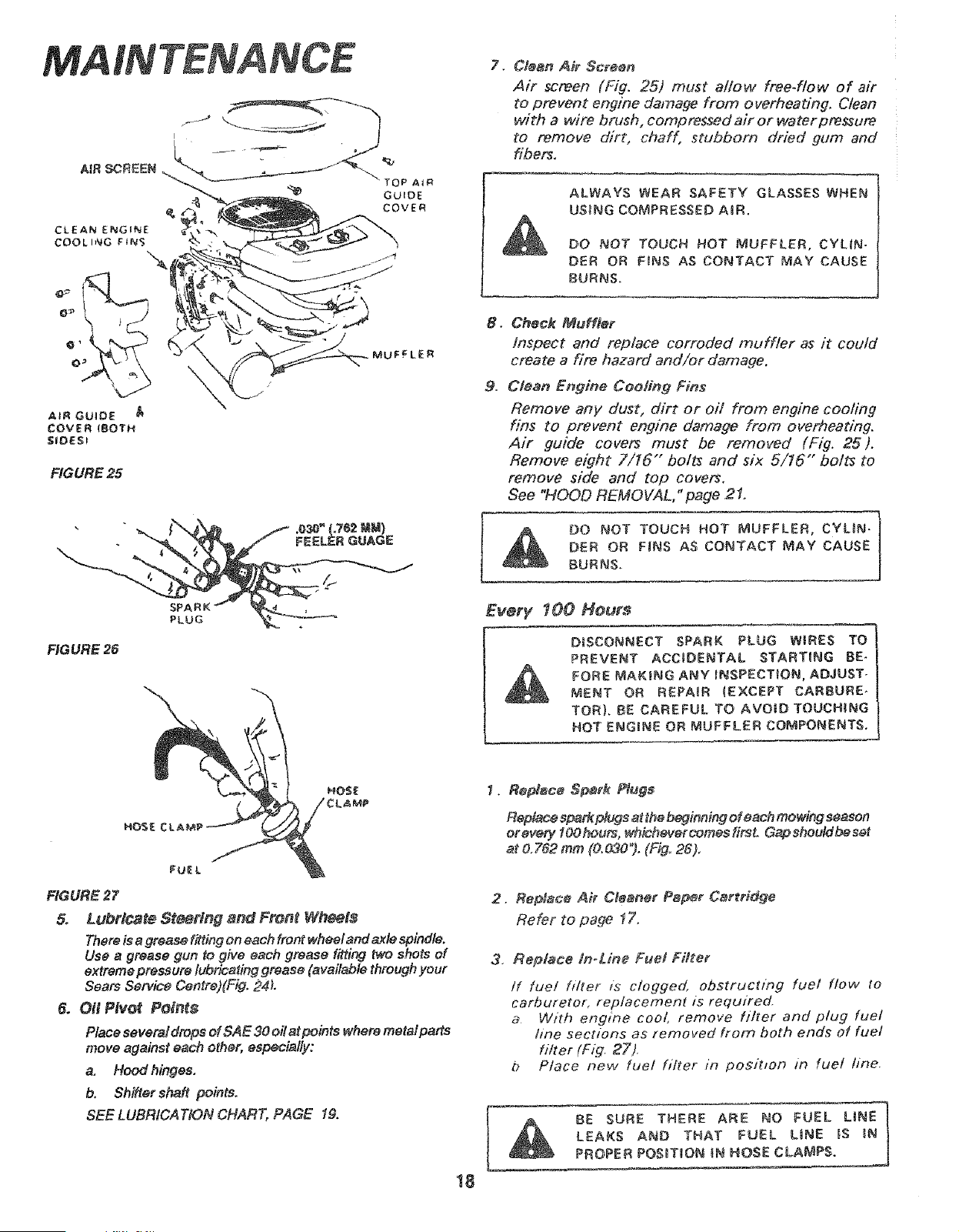
7. CJean Air Screen
Air screen (Fig. 25) must allow free-flow of air
to prevent engine damage from overheating, Clean
with a wire brush, compressed air or water pressure
to remove dirt, chaff, stubborn dried gum and
fibers,
ALWAYS WEAR SAFETY GLASSES WHEN
USING COMPRESSED AiR.
DO NOT TOUCH HOT MUFFLER, CYLIN-
DER OR FINS AS CONTACT MAY CAUSE
8URNS.
, Chock MuHler
Inspect and replace corroded muffler as it could
create a fire hazard and/or damage.
9. Clean Engine Cooling Fins
Remove any dust, dirt or oH from engine cooling
fins to prevent engine damage from over, heating.
Air guide covers must be removed (Fig. 25).
Remove eight 7/I6"" bolts and six 5/16" bolts to
remove side and top covers.
See "HOOD REMOVAL," page 2t.
DER OR F_NS AS CONTACT MAY CAUSE
BURNS.
EvefF 100 Hours
DISCONNECT SPARK PLUG W{RES TO
PREVENT ACCIDENTAL STARTING BE-
FORE MAKING ANY INSPECTION, ADJUST-
MENT OR REPAIR {EXCEPT CARBURE*
TOR}. BE CAREFUL TO AVOID TOUCHING
HOT ENGmNE OR MUFFLER COMPONENTS.
FU_L
RGURE 27
5_ Lubricate St_rtng and Fron_ Wheels
There is a grease fitting on each front wheel and _le spindle.
Use a grease gun to give each grease fitting _o shots of
extreme pressure lubricating grease (available through your
Sears Service Centre)(Fig. 24L
6. Oit Pivof Poin_s
Place several drops ef SAE 30 oilat points where metai parts
move against each other, especially:
a, Hood hinges,
b. Shifter shaft points.
SEE LUBRICATION CHART, PAGE !&
18
1. Ro_ac_ £8:_r_ Piuge
Ropl_co sp_rk plugs at the beginning of each mowing season
er every l OOheurs, whichever comes first. Gap shoutd be set
at 0,762 mm (&&_O*). (Fig. 26),
.
Replaco Air CJeaner Pa_r Cartridge
Refer to page ! Zo
3. Replace/n_Line Fuel Fill'or
tf fuet h/zer is clogged, obstructing fuel flow to
carburetor, replacement is required.
a With engine cool, remove filter and plug fuel
hne sections as removed from both ends of fuel
biter (Fig_ 2_').
b P/ace new fuel filter _n posit_on m fuel fine.
_ BE SURE THERE ARE NO FUEL LiNE
LEAKS AND THAT FUEL L_NE _S _N
PROPER POS_T_ON _N HOSE CLAMPS.
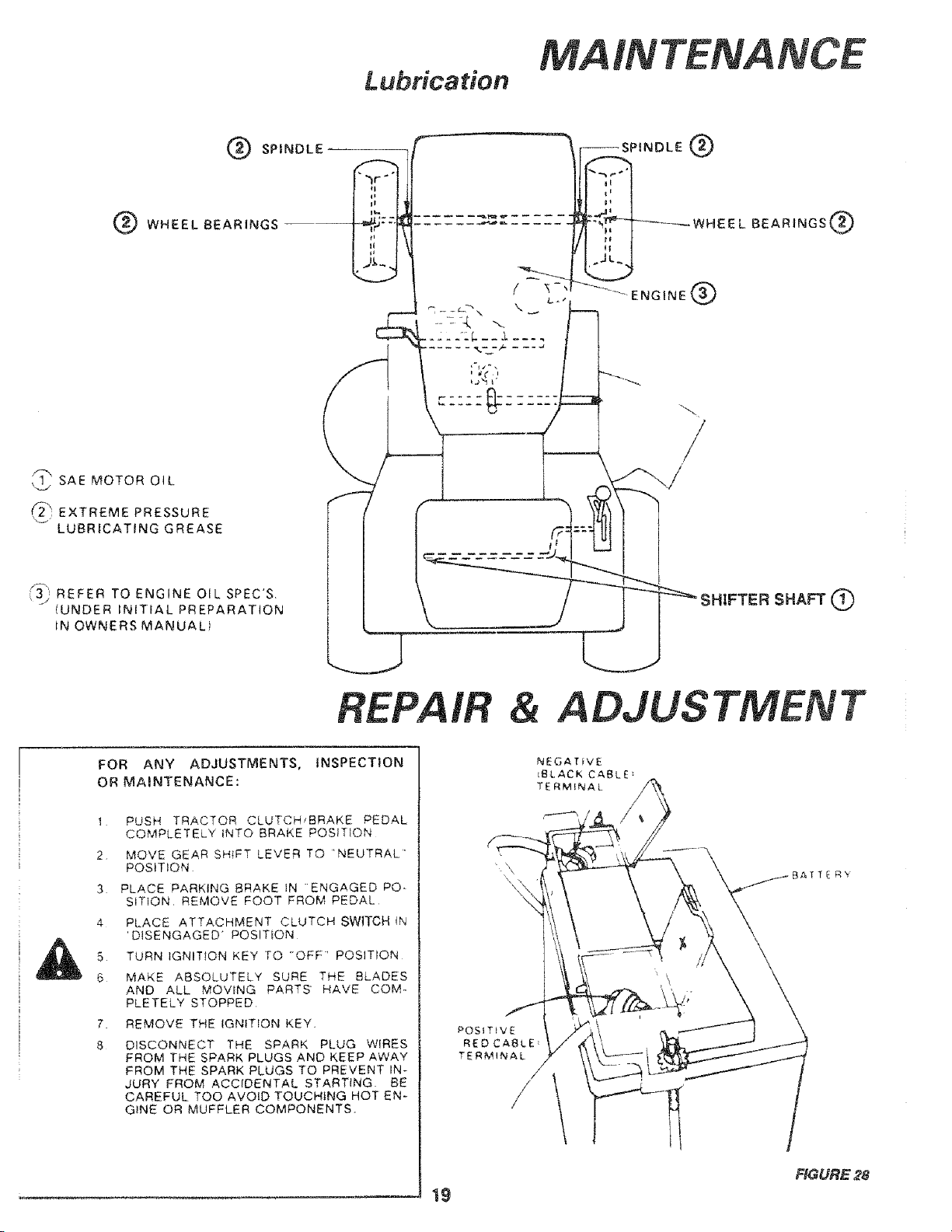
Lubrication
INTENANCE
SPINDLE
WHEEL BEARINGS
,_ SAE MOTOR OIL
_ EXTREME PRESSURE
LUBRICATING GREASE
'_3) REFER TO ENGINE OIL SPEC'S
IUNDER INITIAL PREPARATION
IN OWNERSMANUAL1
.--SPINDLE Q
"qr
Lt
--_-_----- WH E E L BEARINGS_
ENGINE (_
REPAIR & ADJUSTMENT
FOR ANY ADJUSTMENTS, INSPECTION
OR MAINTENANCE:
1 PUSH TRACTOR CLUTCH_BRAKE PEDAL
COMPLETELY INTO BRAKE POSITION
2 MOVE GEAR SHIFT LEVER TO 'NEUTRAL'
POSITION
3 PLACE PARKING BRAKE IN "ENGAGED PO-
SITION, REMOVE FOOT FROM PEDAL
4 PLACE ATTACHMENT CLUTCH SWITCH tN
'DISENGAGED' POSITION
5 TURN IGNITION KEY TO "OFF" POSITION
6 MAKE ABSOLUTELY SURE THE BLADES
AND ALL MOVING PARTS HAVE COM-
PLETELY STOPPED
7.
8
REMOVE THE IGNITION KEY,
DISCONNECT THE SPARK PLUG WIRES
FROM THE SPARK PLUGS AND KEEP AWAY
FROM THE SPARK PLUGS TO PREVENT IN-
JURY FROM ACCIDENTAL STARTING BE
CAREFUL TOO AVOID TOUCHING HOT EN-
GiNE OR MUFFLER COMPONENTS,
!9
FIGURE 28
REPAIR & ADJUSTMENTS
LEAD-ACID BA'TTERIES GENERATE
E×PLOS_VE GASES. KEEP SPARKS,
FLAME AND SMOKING MATER!_ALS
AWAY FROM BATTERIES. ALWAYS
WEAR EYE PROTECTION WHEN
AROUND BATTERIES.
SPARK
PLUG
SPARK
PLUG
:ARBURETOR
FIXED MAIN
JET COVER
(HtGH
RGURE 30
20
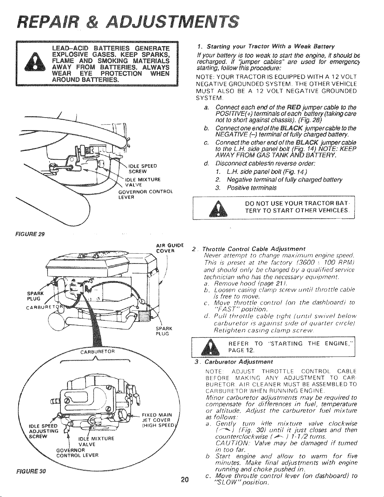
I. Starting your Tractor With a Weak Battery
tf your battery is too weak to start the engine, it should be
recharged. If 'Jumper cables" are used for emergenc_
starting, follow this procedure:
NOTE: YOUR TRACTOR IS EQUIPPED WITH A 12 VOLT
NEGATIVE GROUNDED SYSTEM. THE OTHER VEHICLE
MUST ALSO BE A 12 VOLT NEGATIVE GROUNDED
SYSTEM.
a. Connect each end of the RED jumper cable to the
POSITIVE(+) terminals of each battery (taking care
not to short against chassis). (Fig. 28)
b. Connect one end of the BLACK jumper cable to the
NEGATIVE (-) terminal of fully charged battery.
c. Connectthe otherendofthe BLACK jumpercable
to the L.Ho side panel bolt (Fig. 14) NOTE: KEEP
AWAY FROM GAS "tANK AND BATTERY.
d. Disconnect cablesfin reverse order:
1. LH. side panel bolt (Fig. !4)
2. Negative terminal of fully charged battery
& Pos#ive terminals
A DO NOT USE YOUR TRACTOR BAT-
TERY TO START OTHER VEHICLES,
2,
Throttle Control Cable Adjustment
Never attempt to change maximum engine speed,
This is preset at the factory (3600 ; 100 RPM)
and should only be changed by a qualified service
technician who has _¢tenecessary equlpment,
a. Remove hood (page 21L
b. Loosen casing clamp screw until throttle cable
is free to move,
c. Move throttle control (on d_e dashboard) to
"'FA S T" position.
d. Pull throttle cable tight (Uf?tl/ SWiVel below
carburetor zs against s/de of quarter c/rc/et
Retighten casing clamp screw
REFER TO "STARTING THE ENGINE,"
PAGE 12,
Carbure_o¢ Adjustment
NOTE: ADJUST THROTTLE CONTROL CABLE
BEFORE MAKING ANY ADJUSTMENT TO CAR-
BURETOR AIR CLEANER MUST BE ASSEMBLED TO
CARBURETOR WHEN RUNNING ENG{NE,
Minor carburetor adjustments may be required to
compensate for differences in fuel, temperature
or altitude. Adjust the carburetor fuel mixture
as follows:
a, Gently turn irt/e mixture valve clockwise
(f-_-) (Fig, 30) until it just closes and then
counterclockwise (._- ) f-1/2 turns.
CAUTION. Valve may be damaged if turned
in too far.
b Start engine and allow to warm for five
minutes. Make final adjustments with engine
running and choke pushed in.
c. Move thro_de control lever (on dashboard) to
"SLOW'" position.
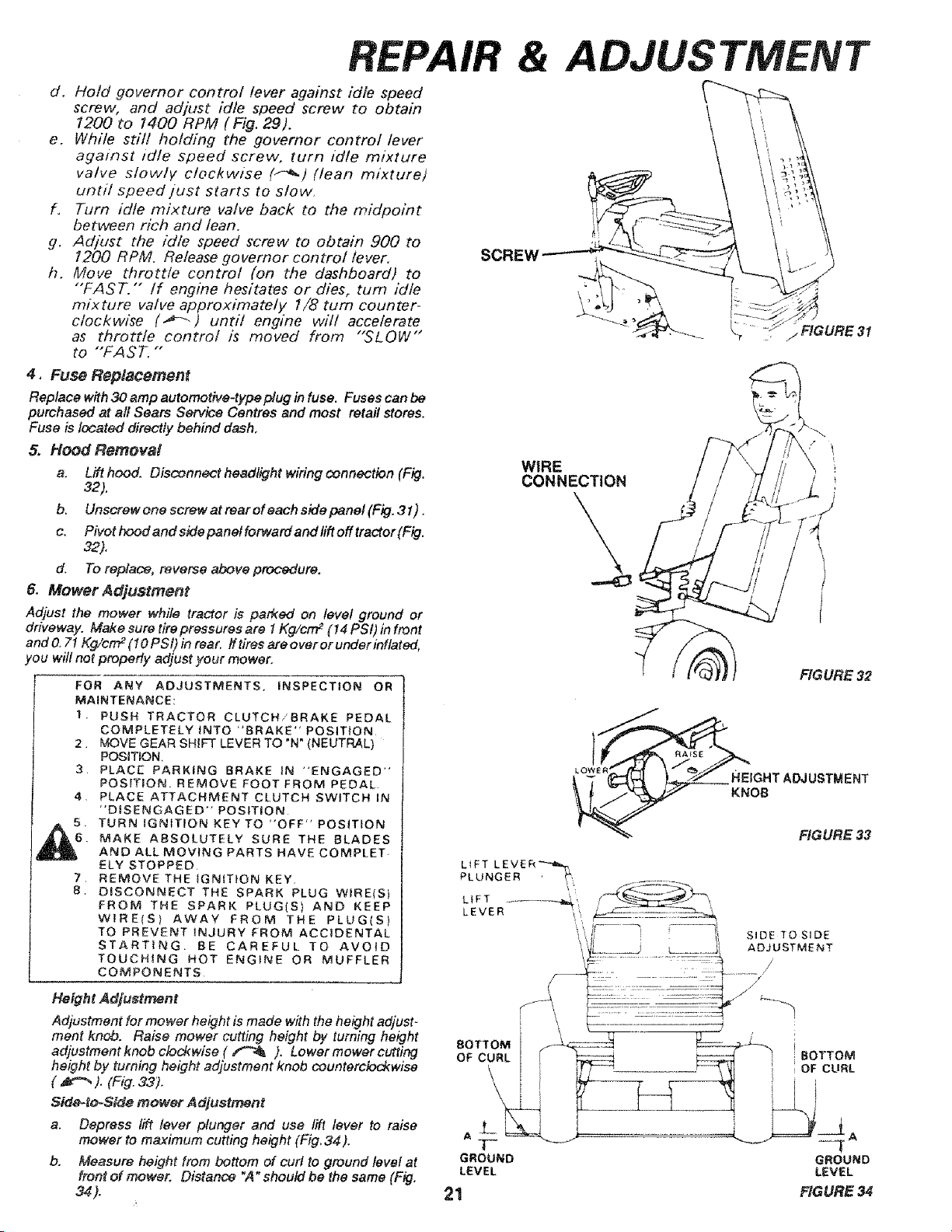
d, Holdgovernorcontrol leveragainstidle speed
screw,and adjust idle speedscrewto obtain
1200to 1400RPM(Fig.29).
e. Whilestill holding the governorcontrol lever
against idle speedscrew, turn idle mixture
valve slowly clockwise (_) (lean mixture)
until speed just starts to slow.
f. Turn idle mixture valve back to the midpoint
between rich and lean.
g. Adjust the idle speed screw to obtain 900 to
!200 RPM. Release governor control lever,
h. Move throttle control (on the dashboard) to
"'FAST. "" /f engine hesitates or dies, turn idle
mixture valve approximately 1/8 rum counter-
clockwise (_---) undl engine will accelerate
as throttle control is moved from "SLOW"
to "FAST. ""
4, Fuse Replacement
Replace with 30 amp automotive4ype[duginfuse. Fusescanbe
purchased at al! Sears ServiceCentresand most retail stores.
Fuse is located directlybehind dash,
5, Hood Removal
a. Lift hood. Oisconnect headlight wiring connection (Fig,
32).
b, Unscrew one screw at rear of each side panel (Fig. 31) .
c. Pivot hood and side panel forward and lift off tractor (Fig.
32)°
d. To replace, reverse above procedure.
& Mower Adjustment
Adjust the mower while tractor is parked on level ground or
driveway. Make sure tire pressures are 1Kg/crrF (14 PSI) in front
and O.71Kg/cm 2(I0 PSi) in rear, ff tires are over or under inflated,
!ou will not properly adjust your mower.
FOR ANY ADJUSTMENTS, iNSPECTION OR
MAINTENANCE:
1. PUSH TRACTOR CLUTCH/BRAKE PEDAL
COMPLETELY INTO "BRAKE" POSIT{ON
2. MOVE GEAR SHIFT LEVER TO "N" (NEUTRAL)
POSITION,
3. PLACE PARKING BRAKE IN "ENGAGED"
POSITION. REMOVE FOOT FROM PEDAL
4, PLACE ATTACHMENT CLUTCH SWITCH IN
"DISENGAGED" POSITION
5. TURN IGNITION KEY TO "'OFF" POSITION
6. MAKE ABSOLUTELY SURE THE BLADES
AND ALL MOVING PARTS HAVECOMPLET-
ELY STOPPED
7 REMOVE THE IGNITION KEY.
8 DISCONNECT THE SPARK PLUG WIRE<S)
FROM THE SPARK PLUG(S) AND KEEP
WIRE(S) AWAY FROM THE PLUG(S)
TO PREVENT _NJURY FROM ACCIDENTAL
STARTING BE CAREFUL TO AVOID
TOUCHING HOT ENGINE OR MUFFLER
COMPONENTS
Height Adjustment
Adjustment for mower height is made with the height adjust _
ment knob. Raise mower cutting height by turning height
adjustment knob clod{wise ( _ ). Lower mower cutfing
height by turning height adjustment knob counterclockwise
( _ ). (Fig.33).
Sido-to-Side mower Adjustment
a. Depress lift lever plunger and use lift lever to raise
mower to maximum cutting height (Fig, 34).
b. Measure height from bottom of curl to ground level at
front of mower. Distance "A" should be the same (Fig.
34).
WIRE
CONNECTION
FIGURE 32
HEtGHTADJUSTMENT
KNOB
FIGURE 33
L_FT L E V E R _,_._,
PLUNGER _',
LEVER '!',, . ..........
• ,J i SIDE TO SIDE
i 'L_.._ L_ ....... ADJUSTMENT
..........::,:.: ........._y,i
BOTTOM [ _ _ iBOTTOM
OF CURL { iF_ r_ '_I i OF CURL
GROUND GROUND
LEVEL LEVEL
21 FIGURE 34
REPAIR & ADJUSTMENT
FiGURE 35
f
FLANGE
\
LiFT LEVER
PLUN
22
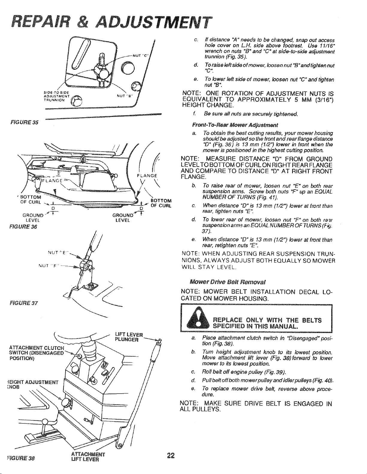
d.
e,
If distance "A" needs to be changed, snap out access
hote cover on L.H. side above footrest, Use tl/16"
wrench on nuts "B" and "C" at side-to-side adjustment
trunnion (Fig. 35).
To raise left side of mower, loosen nut "B" and tighten nut
"C".
To lower left side of mower, loosen nut "C" and tighten
nut "B:
NOTE: ONE ROTATION OF ADJUSTMENT NUTS iS
EQUIVALENT TO APPROXIMATELY 5 MM (3/16")
HEIGHT CHANGE.
f. Be sure allnuts are securely tightened.
Front- To-Rssr Mower Ad]ustment
a. To obtain the best cutting results, your mower housing
should be adjusted so the front and rear flange distance
"D" (Fig. 36) is t3 mm (1/2") lower in front when the
mower is positioned in the highest cutting position.
NOTE: MEASURE DISTANCE "D" FROM GROUND
LEVELTO BOTTOM OF CURL ON RIGHT REAR FLANGE
AND COMPARE TO DISTANCE "D" AT RIGHT FRONT
FLANGE,
b. To raise rear of mower, loosen nut mE"on both rear
suspension arms. Screw both nuts "F" up an EQUAL
NUMBER OF TURNS (Fig. 41).
c. When distance "D" is 13 mm (1/2") lower at front than
rear, tighten nuts "E".
d. To lower rear of mower, loosen nut "F" on both re_t
suspension arms an EQUAL NUMBER OF TURNS (Fig.
37).
e. When distance "D" is 13 mm (1/2") lower at front than
rear, retighten nuts "E%
NOTE: WHEN ADJUSTING REAR SUSPENSION TRUN-
NIONS, ALWAYS ADJUST BOTH EQUALLY SO MOWER
WILL STAY LEVEL.
Mower Drive Belt Removal
NOTE: MOWER BELT iNSTALLATiON DECAL LO-
CATED ON MOWER HOUSING.
a. Place attachment clutch switch in "Disengaged" posi.
tion (Fig. 38).
b, Turn height adjustment knob to its lowest position.
Move attachment lift lever (Fig. 38)forward to lower
mower to its lowest position.
c, Roll belt off engine pulley (Fig. 39).
d. Pull belt off both mower pulley and idler pulteys (Fig. 40),
e. To raplace mower drive belt, reverse above proce-
dure.
NOTE: MAKE SURE DRIVE BELT IS ENGAGED IN
ALL PULLEYS.
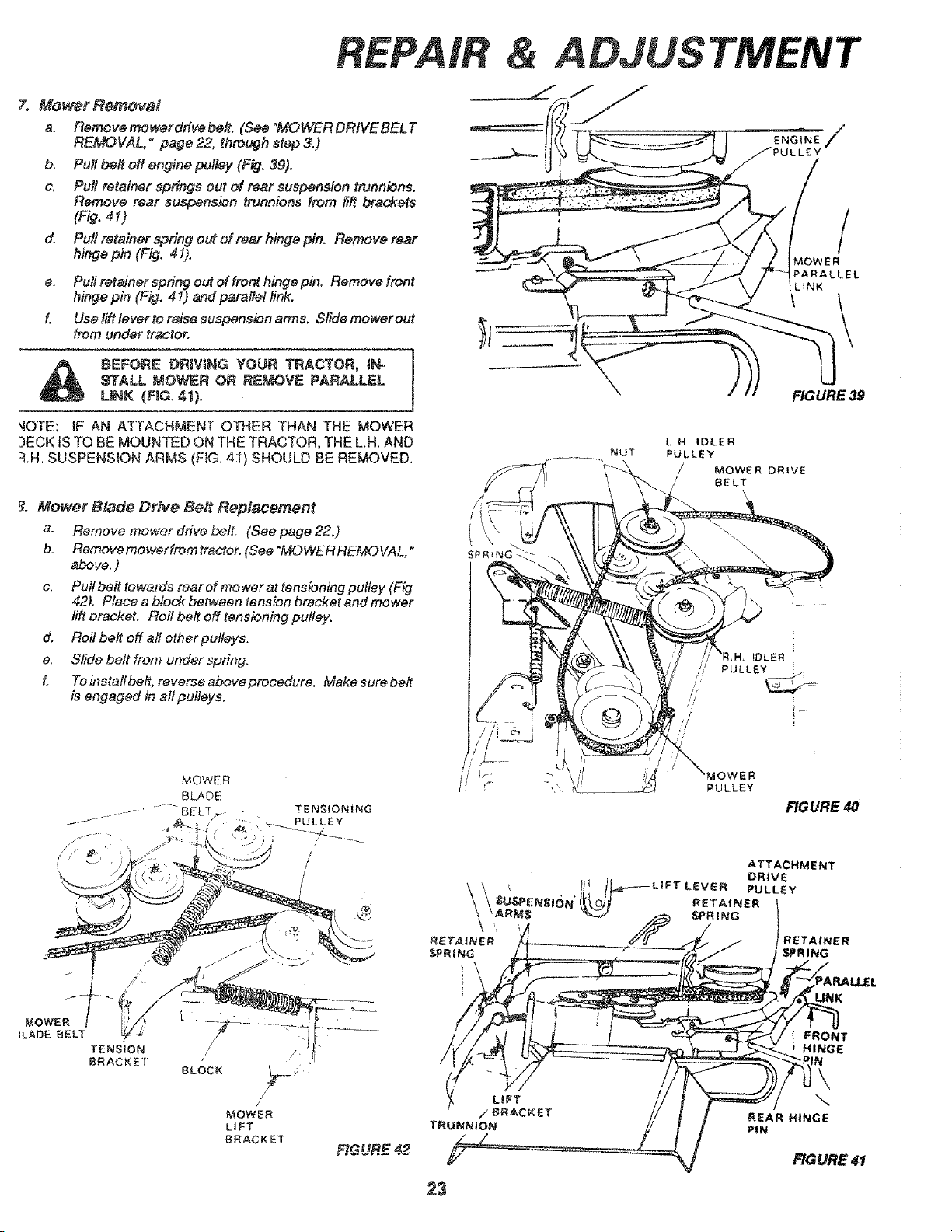
7o Mower Retrieval
a, Remove mower dfive be#. (See "MOWER DRtVE BEL T
REMOVAL," page 22, through slop 3.)
b. Pull bel_ off engine pulley (Fig. 39),
c, Pull retainer spdngs out of rear suspension trunnions.
Remove rear suspension trunnions from lift brackets
(Fig. 41)
d. Pu# retainer spring out of rear hinge pin. Remove rear
hinge pin (Fig. 41),
e. Pu# refainer spring out of front hinge pin. Remove front
hinge pin (F_. 41) and parallel link.
f, Use tift tever to r_se suspension armso Slide mower out
from under tr_ctor,
BEFORE DRiViNG YOUR TRACTOR, IF_
STALL MOWER OR RE&,_OVE PARALLEL
LiNK (F{G. 41).
'4OTE: iF AN ATTACHMENT O]34ER THAN THE MOWER
3ECK tS TO BE MOUNTED ON THE TRACTOR, THE LH. AND
::LH.SUSPENSION ARMS (F_. 4_) SHOULD BE REMOVED.
_. Mower Blade Drive Be# RepJacernent
a. Remove mower drive belt, (See page 22°)
b. Removemowerfromtractor. (See"MOWERREMOVAL,"
above, )
c, Pull beit towards rear of mower at tensioning pulley (Fig
42). Place a block bePween tension bracket and mower
lift bracket, Roll belt off tensioning pulley.
d. Roll belt off all other pulleys.
e, Slide bett from under spring.
f, To instafl be#, reverse above procedure. Make sure belt
is engaged in alf pulleys,
ADJUS
/
_OWER
PARALLEL
LiNK
FIGURE 39
MOWER DRIVE
BELT
BLOCK //_== /
MOWER
LiFT
BRACKET
RGUR_= 42
23
_OWER
PULLEY
LEVER
RETAINER
SPRING
/
FIGURE 4O
ATTACHMENT
DRIVE
PULLEY
RETAtNER
SPRING
UNK
FRONT
HINGE
\
REAR HINGE
PiN
FIGURE 41
&
FRAME
TRANSAXLE
PULLEY
FIGURE 43
CLUTCH|NI
iDLER
ELECTRIC
CLUTCH
CLUTCH
LOCATER
SQUARE KEY
(REAR ONLY)
FIGURE 45
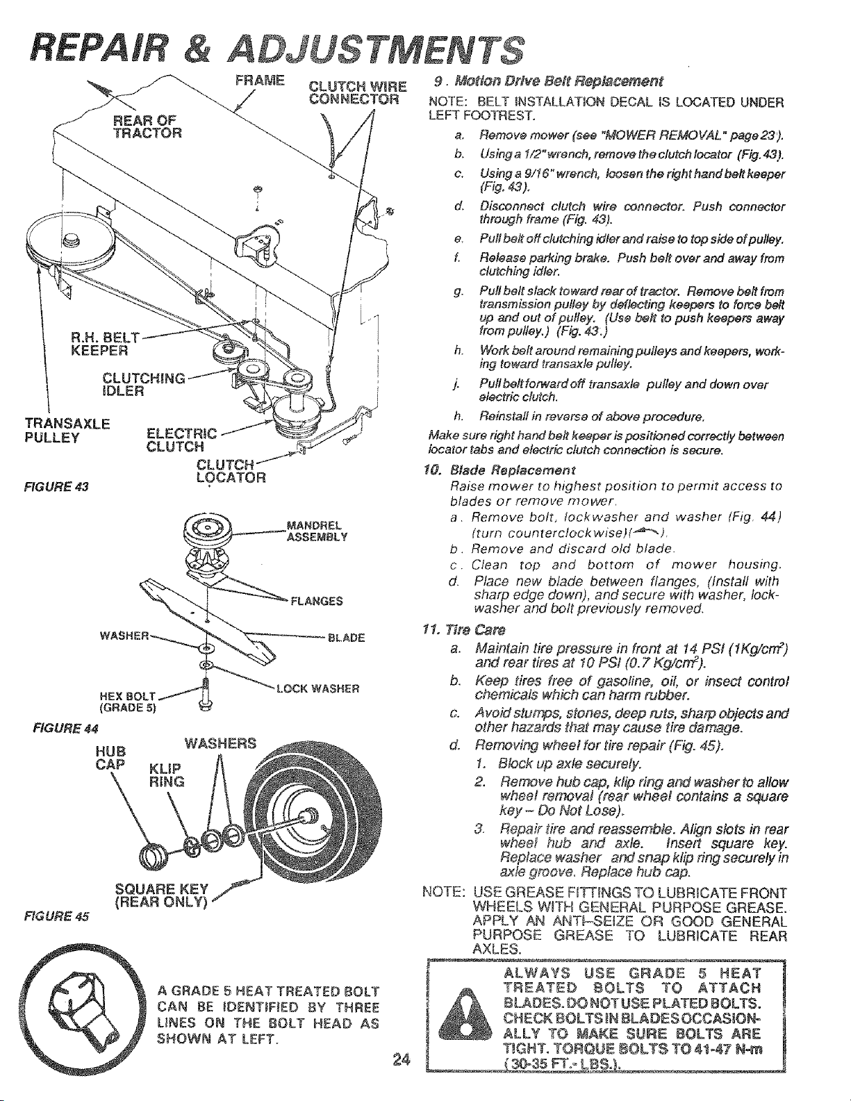
A GRADE 5 HEAT TREATED BOLT
CAN BE IDENTiFiED BY THREE
UNES ON THE BOLT HEAD AS
SHOWN AT LEFT.
2,$
9. Motion Drfve Bait Rept,_coment
NOTE: BELT INSTALLATION DECAL iS LOCATED UNDER
LEFT FOOTREST.
a. Remove mower (see "MOWER REMOVAL" page23).
b. Usinga 1/2"wrench, removethectutchlecater (Fig,43),
c. Using a 9116" wrench, l_sen the right hand be# keeper
(Fig, 43).
d. Disconnect clutch wire connector. Push connector
through frame (Fig. 43).
e. Pull be# off clutching idler and raise to top side of pulley,
f. Release parking brake. Push be# ever and away from
clutching idler.
g. Pull belt slack toward rear ef tractor, Remove be# from
transmission pulley by deflecting keepers to force belt
up and out of pulley. (Use belt to push keepers away
from pulley.) (Fig. 43:)
h. Work belt around remaining pulleys and keepers, work-
ing toward transaxle pulley.
j. Pull be#fomcard off transaxle pulley and down over
electric clutch.
h. Reinstall in reverse of above procedure,
Make sure right hand be# keeper is positioned correctly between
locater tabs and electric clutch connection is secure.
10, Blade Replacement
Raise mower to highest position to permit access to
blades or remove mower.
a. Remove bolt, Iockwasher and washer (Fig. 44)
(turn counterclockwiset(_'_" ).
b. Remove and discard old blade.
c. Clean top and bottom of mower housing.
d. Place new blade belween flanges, (install with
sharp edge down), and secure with washer, lock-
washer and bolt previously removed.
11. Tire Csre
a. Maintain tire pressure in front at 14 PSi (1Kg/cm 2)
and rear tires at I0 PSi (0. 2"Kg/cm2).
b. Keep tires free of gasoline, oil, or insect control
chemicals which can harm nJbbero
& Avoid stumps, stones, deep ruts, sharp objects and
other hazards that may cause tire damage.
do Removing wheel for tire repair (Fig. 45).
1. Block up axle securely.
2. Remove hub cap, ktip ring and washer to allow
whee! removal (rear wheel contains a square
key - Do Not Lose).
3. Repair tire and reassemble. Align slots in rear
whee_ hub and _le. fnsert square key.
Replace washer and snap klip ring securely in
axle groov& Replace hub cap.
USE GREASE F_TTINGS TO LUBRICATE FRONT
WHEELS W_TH GENERAL PURPOSE GREASE.
APPLY AN ANT_-SEIZE OR GOOD GENERAL
PURPOSE GREASE TO LUBRICATE REAR
AXLES.
NOTE:
ALWAYS USE GRADE 5 HEAT
TREATED BOLTS TO ATTACH
BLADES. DO NOTUSE PLATED BOLTS.
CHECK E_OLTS _N8LADES OCCASJONo
ALLY TO MAKE SURE BOLTS ARE
T_GNT. TORQNE 8OLTS TO 41-47 N-m
ADJUSTMENT
[
WHEN MOUNTING TIRES, UNLESS BEADS
ARE SEATED, OVER iNFLATiON CAN
CAUSE AN EXPLOSION,
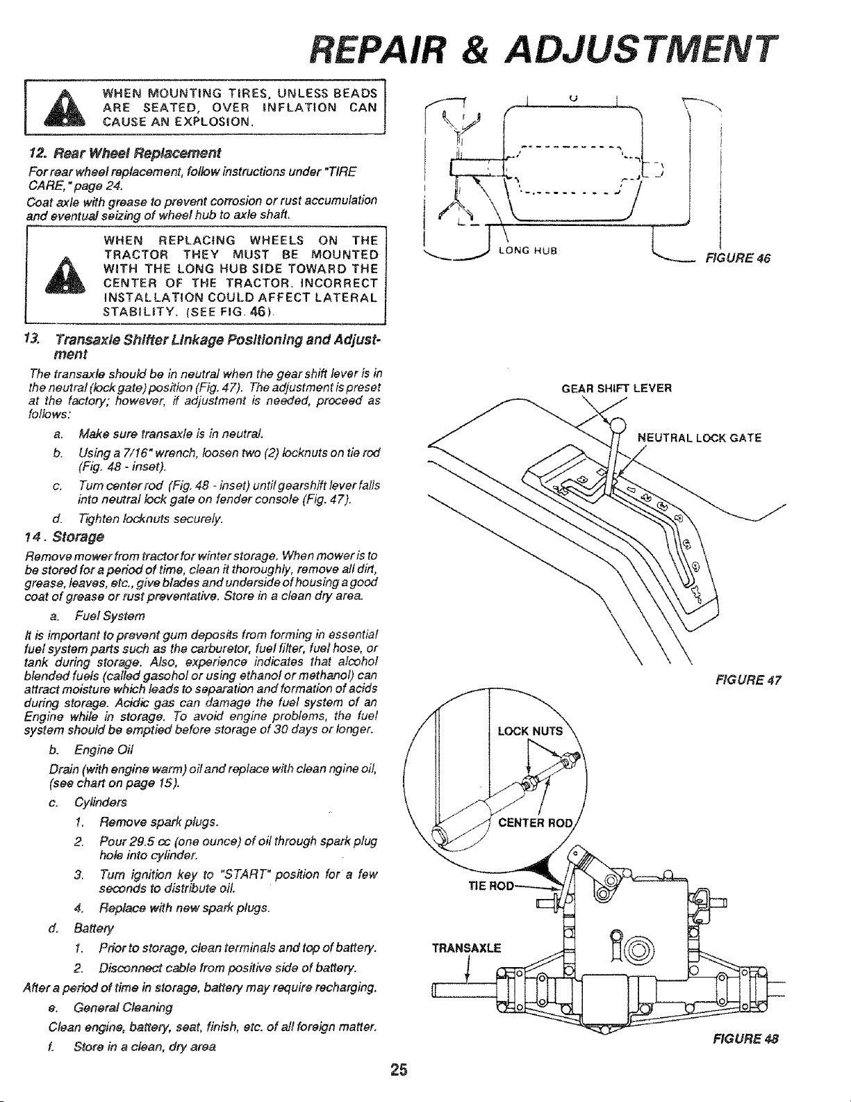
12. Rear Wheel Repla¢ement
For rear wheel replacement, follow instructions under "TIRE
CARE, "page 24.
Coat axle with grease to prevent corrosion or rust accumulation
and eventual seizing of wheel hub to axle sha&
WHEN REPLACING WHEELS ON THE
TRACTOR THEY MUST BE MOUNTED
WITH THE LONG HUB SiDE TOWARD THE
CENTER OF THE TRACTOR. INCORRECT
INSTALLATION COULD AFFECT LATERAL
STABILITY. (SEE FIG, 46),
t u _ I-_--'.
_J
!
UB _ FIGURE 46
13. Transaxte Shifter Linkage Positioning and Adjust-
ment
The transaxle should be in neutral when the gear shift lever is in
the neutral (lock gate) position (Fig, 47). The adjustment is preset
at the factory; however, if adjustment is needed, proceed as
follows:
a" Make sure transaxte is in neutral.
b, Using a 7/16" wrench, !oosen two (2) locknuts on tie rod
(Fig, 48 - inset).
c. Turn center rod (Fig, 48 - inset) until gearshift lever falls
into neutral lock gate on fender console (Fig. 47).
d. Tighten ldd_nuts securely.
14. Storage
Remove mowerfrom tractorfor winter storage. When mower is to
be stored for a period of time, clean it thoroughly, remove all dirt,
grease, leaves, ete., give blades and underside of housing a good
coat of grease or rust preventative. Store in a clean dry area.
a, Fuel System
It is important to prevent gum deposits from forming in essential
fuel system parts such as the carburetor, fuel filter, fuef hose, or
tank during storage. Also, experience indicates that alcohol
blended fuels (called gasohol or using ethanol or methanol) can
attract moisture which leads to separation and formation of acids
during storage, Addic gas can damage the fuel system of an
Engine while in storage. To avoid engine problems, the fuel
system should be emptied before storage of 30 days or longer.
b. Engine Oil
Drain (with engine warm) oil and replace with clean ngine oil,
(see chart on page 15).
c, Cylinders
1. Remove spark plugs.
2, Pour 29,5 cc (one ounce) of oil through spark plug
hole into cylinder,
3, Turn ignition key to "START" position for a few
seconds to distribute oil.
4, Replace w#h new spark plugs.
d, Battery
1. Prior to storage, clean terminals and top of battery.
2. Disconnect cable from positive side of battery,
After a period of time in storage, battery may require recharging.
e. General Cleaning
Clean engine, battery, seat, finish, etc. of all fore_n matter,
L Store in a clean, dry area
GEAR SHIFTLEVER
NEUTRAL LOCK GATE
FIGURE 47
TRANSAXLE
H
FIGURE 48
25
TROUBLESHOOTING
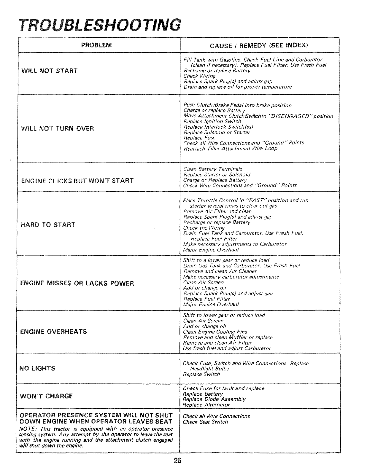
WiLL NOT START
WiLL NOT TURN OVER
PROBLEM CAUSE / REMEDY (SEE iNDEX}
ENGINE CLICKS BUT WON'T START
4ARD TO START
ENGINE MISSES OR LACKS POWER
ENGINE OVERHEATS
NO LIGHTS
WON'T CHARGE
OPERATOR PRESENCE SYSTEM WILL NOT SHUT
DOWN ENGINE WHEN OPERATOR LEAVES SEAT
NOTE. This tractor is equipped with an operator presence
sensing system. Any attempt by the operator to leave the seat
with the engine running and the attachment clutch engaged
shut down the engine.
Fill Tank with Gasoline. Check Fuel Line and Carburetor
(clean if necessary), Replace Fuel Filter. Use Fresh Fuel
Recharge or replace Battery
Check Wiring
Replace Spark Plug(s) and adjust gap
Drain and replace oit for proper temperature
Push Clutch/Brake Pedal into brake position
Charge or replace Battery
Move Attachment Clutch Switch to "'DISENGA GED" position
Replace Ignition Switch
Replace interlock Switch(es)
Replace Solenoid or Starter
Replace Fuse
Check a/t Wire Connections and "Ground'" Points
Reattach Tiller Attachment Wire Loop
Clean Battery Terminals
Replace Szarter or Solenoid
Charge or Replace Battery
Check Wire Connections and "'Ground" Points
Place Throttle Control in "FAST" posit/on and run
starter several tflnes to clear out gas
Remove Air Filter and clean
Replace Spark Plug(sf and adjust gap
Recharge or replace Battery
Check the Wiring
Drain Fuel Tank and Carburetor. Use Fresh Fuel.
Replace Fuel Filter
Make necessary adjustments to Carburetor
Major Engine Overhaul
Shift to a lower gear or reduce load
Drain Gas Tank and Carburetor. Use Fresh Fuel
Remove and clean Air Cleaner
Make necessary carburetor adjustments
Clean Air Screen
Add or change oil
Replace Spark Plug(s) and adjust gap
Replace Fuel Filter
Major Engine Overhaul
Shift to/owergear or reduce load
Clean Air Screen
Add or change oil
Clean Engine Cooling Fins
Remove and clean Muffler or replace
Remove and clean Air Filter
Use fresh fuel and adjust Carburetor
Check Fuse, Switch and Wire Connections. Replace
Headlight Bulbs
Replace Switch
Check Fuse for fault and replace
Replace Battery
Replace Diode Assembly
Replace Alternator
Check all Wire Connections
Check Seat Switch
26
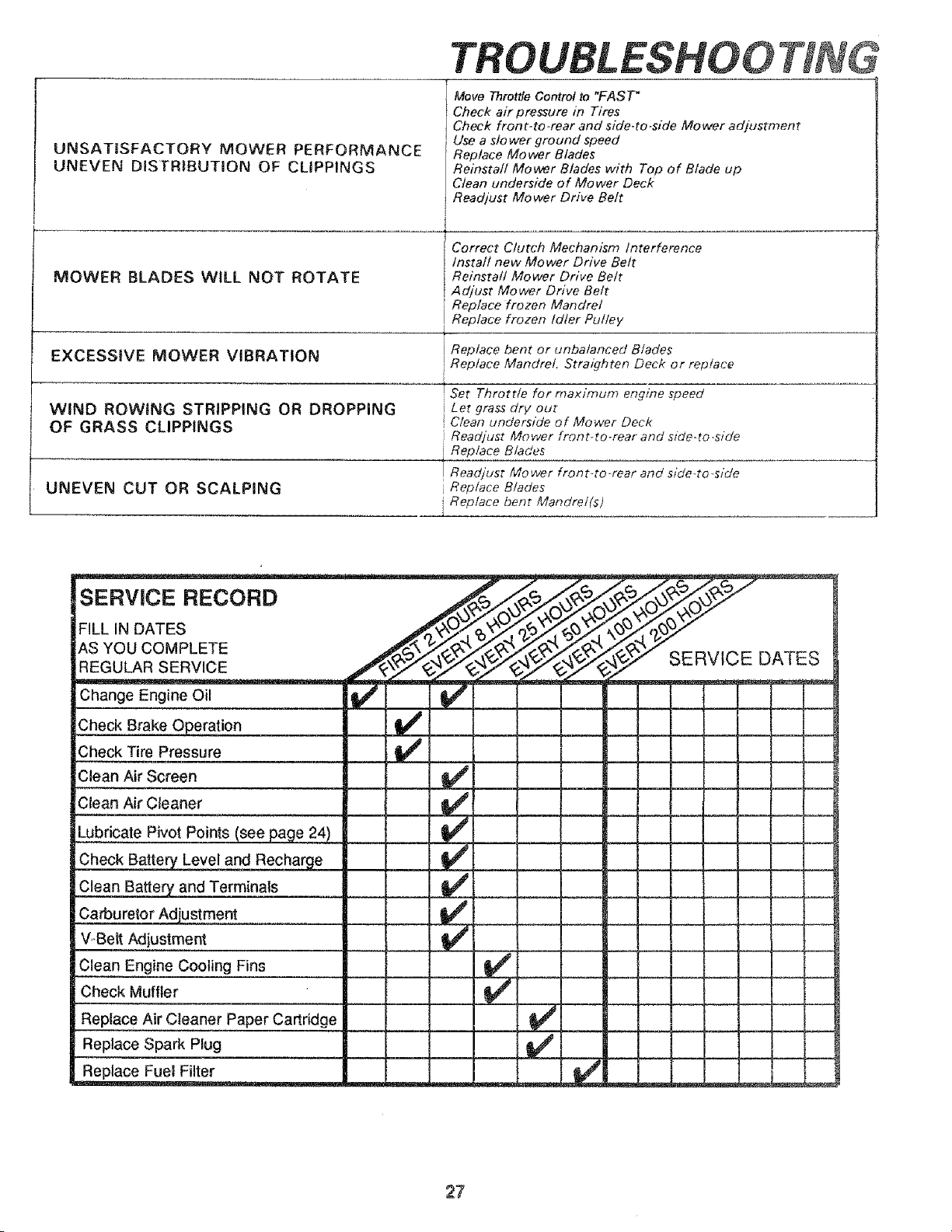
UNSATISFACTORY MOWER PERFORMANCE
UNEVEN DISTRIBUTION OF CLIPPINGS
MOWER BLADES WILL NOT ROTATE
TROUBLESHO0
Move Throttle Control to "FAST"
Check air pressure in Tires
Check front-to-rear and side-to-side Mower adjustment
Use a slower ground speed
Replace Mo wet Blades
Reinstall Mower Blades with Top of Blade up
Clean underside of Mower Deck
Readjust Mower Drive Belt
Correct Clutch Mechanism Interference
lnsta// new Mower Drive Belt
Reinstall Mower Drive Belt
! Adjust Mower Drive Belt
Replace frozen Mandrel
Replace frozen Idler Pulley
EXCESSIVE MOWER VIBRATION Replace bent or unbalanced Blades
Replace Mandrel Stra/_Thten Deck or replace
WIND ROWING STRIPPING OR DROPPING
OF GRASS CLIPPINGS
UNEVEN CUT OR SCALPING
Set Throttle for maximum engine speed
Let grass dr}/out
Clean underside of Mower Deck
Readjust Mower front-to-rear and side-to-side
, Replace Blades
! Readjust Mower front-to-rear and side-to-side
Replace Blades
i Replace bent Mandrel(s)
SERVmCE RECORD
FILL IN DATES
AS YOU COMPLETE
REGULAR SERVICE
Change Engine Oil
!Check Brake Operation
Check Tire Pressure
iClean Air Screen
7
Lubricate Pivot Points (seej3age 24) .__
Check Battery_ Level and Rechar eg_e._ ___
_CJea.nBa_e_ and Terminals
Carburetor Adjustment
V_,BeltAdjustment _
Clean Engine Cooling Fins
Check Muffler
Replace Air Cleaner Paper Cartridge
Replace Spark Plug
Replace Fuel Filter
v'
SERVICE DATES
27
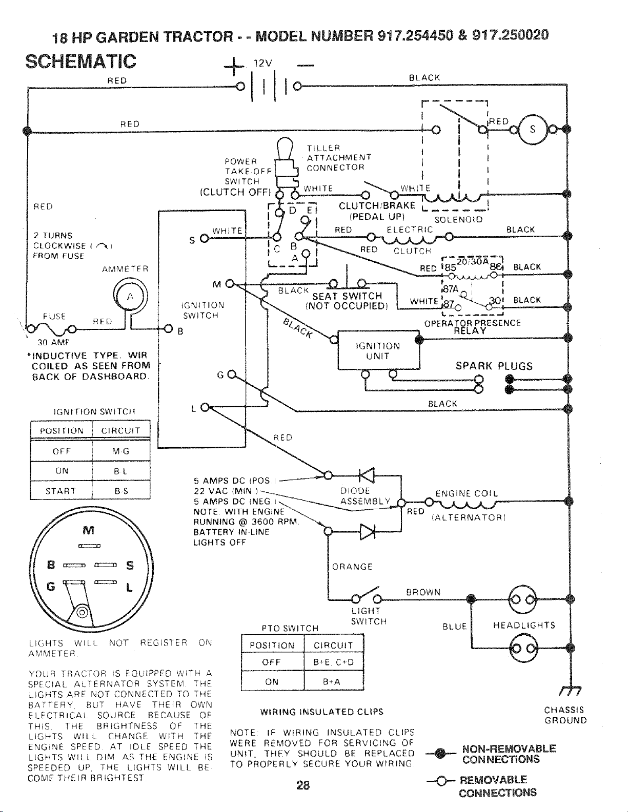
18 HP GARDEN TRACTOR - - MODEL NUMBER 917.254450 & 917.250020
SCHEMATIC _lL --
RED O
RED
RED
2 TURNS
CLOCKWISE t f'_ I
FROM FUSE
AMMETER
F USE 9_------
R E D
30 AMF
*INDUCTIVE TYPE, WIR
COILED AS SEEN FROM
BACK OF DASHBOARD,
IGNITION SWITCH
POSITION i CIRCUIT
OFF MG
ON BL
START BS
LIGHTS WILL NOT REGISTER
AMMETER
M
fGNtTIQN
SWITCH
-OB
12V
BLACK
[" 1
_'_ TILLER t I I
POWER _ ATTACHMENT ' 1
TAKEOFF CONNECTOR I I I
_)" E } CLUTCH!BRAKE L ......
{PEDAL UP}
(_ i SOLENOID
C _ I "_RED CLUTCH r "_-- -
_7A L I
WHITE BLACK
G
BLACK
SEAT SWITCH
(NOT OCCUPIED)
tGNIT1ON
UNIT
OPERATOR PRESENCE
RELAY
SPARK PLUGS
BLACK
RED
5 AMPS DC (POS) ]
22 VAC (MIN)-__.___ DIODE I _ ENGINE COIL
5 AMPS DC (NEG 1.._-_-_._ ASSEMBLY
NOTE: WITH ENGINE _-__ -_'--------- | RED -__--_- _--_
RUNNING @ 36-0-0"/R-PM "_%. h l I - <ALTERNATOR1
BATTERY tN LINE I__..-_/,_..i-_
LIGHTS OFF
ON
YOLIR TRACTOR IS EQUIPPED WITH A
SPECIAL ALTERNATOR SYSTEM THE
LIGHTS ARE NOT CONNECTED TO THE
BATTERY BUT HAVE THEIR OWN
ElECTRiCAL SOURCE BECAUSE OF
THIS, THE BRIGHTNESS OF THE
LIGHTS WILL CHANGE WITH THE
ENGINE SPEED AT IDLE SPEED THE
LIGHTS WILL DIM AS THE ENGINE IS
SPEEDED UP, THE LIGHTS WILL BE
COME THEIR BRIGHTEST
ORANGE
LIGHT
SWITCH
PTO SWITCH
POSITION CIRCUIT
OFF B+E, C÷D
ON B+A
WIRING INSULATED CLIPS
NOTE: IF WIRING INSULATED CLIPS
WERE REMOVED FOR SERVICING OF
UNIT, THEY SHOULD BE REPLACED
TO PROPERLY SECURE YOUR WIRING
28
BROWN BLUE_
F
CHASSIS
GROUND
_NON-REMOVABLE
CONNECTIONS
--O--REMOVABLE
CONNECTIONS
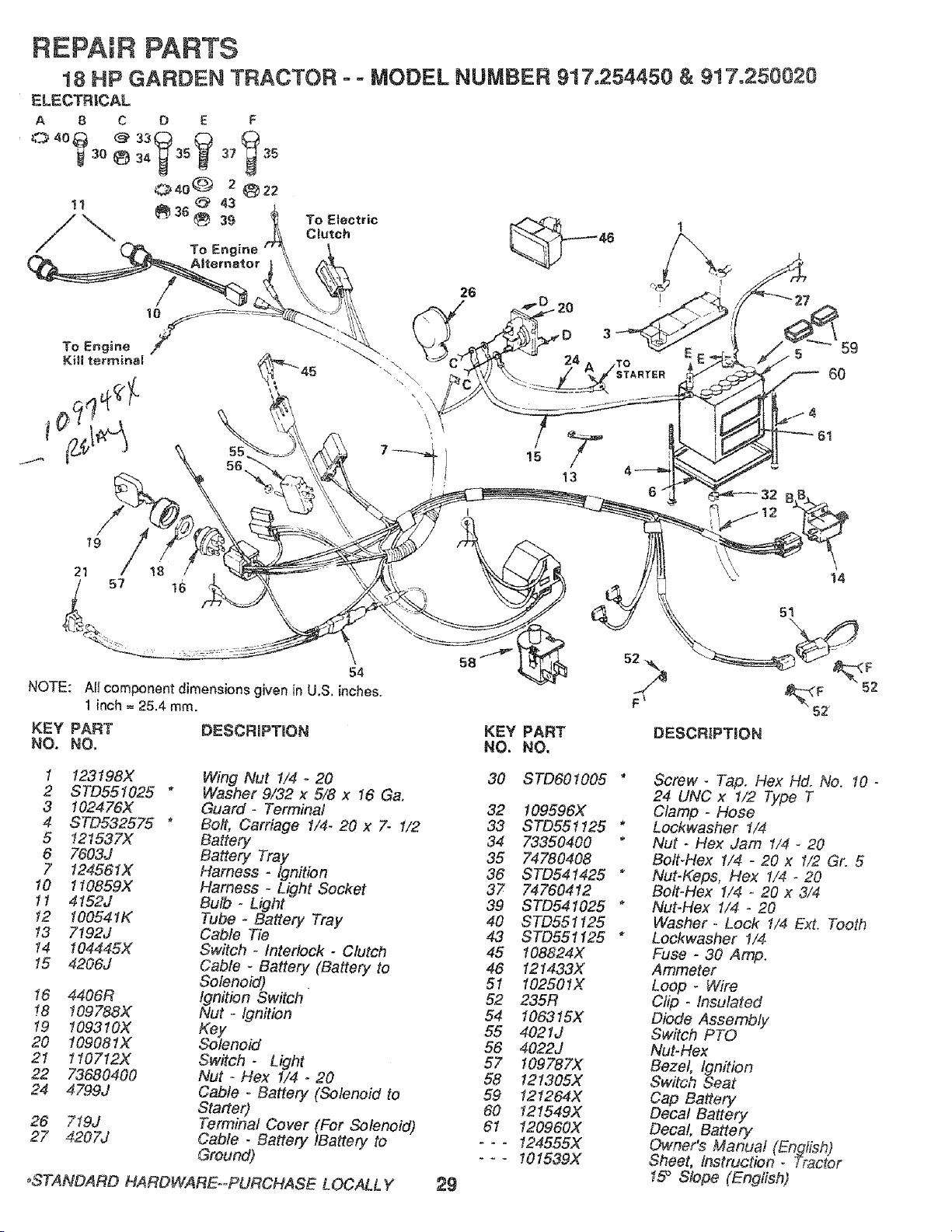
REPAIR PARTS
18 HP GARDEN TRACTOR
To Engine
- = MODEL NUMBER 917,254450 & 917°250020
10
15
13
21
51
\
59
6O
14
54
NOTE: AII component dimensions given in U.S. inches.
1 inch = 25.4 ram.
KEY PART DESCRIPTtON
NO. NO.
1 123198X
2 STD551025 *
3 102476X
4 STD532575 *
5 121537X
6 7603J
7 I24561X
10 1I0859X
11 4152J
!2 100541K
13 7192J
!4 104445X
15 4206J
16 4406R
!8 109788X
19 109310X
20 109081X
21 1lOZ12X
22 73680400
24 4799J
26 719J
27 4207J
Wing Nut 1/4 - 20
Washer 9/32 x 5/8 x 16 Ca.
Guard- Terminal
Bolt, Carriage 1/4- 20 x 7- 1/2
Battery
Battery Tray
Harness - Ignition
Harness - Light Socket
Bulb - Light
Tube * Battery Tray
Cable Tie
Switch - Interlock - Clutch
Cable - Battery (Battery to
Solenoid)
Ignition Switch
Nut - Ignffion
Key
Solenoid
Switch- Light
Nut - Hex 1/4 - 20
Cable - Battery (Solenoid to
Starter)
Terminal Cover (For Solenoid)
Cable - f3attery IBattery to
Ground)
_STANDARD HAROWARE--PURCHASE LOCALLY
KEY PART
NO. NO.
29
30 STD601005"
32 t09596X
33 STD551125 *
34 73350400 *
35 74780408
36 STD541425 *
37 74760412
39 STD541025 *
40 STD551125
43 STD551!25 *
45 108824X
46 121433X
51 102501X
52 235R
54 106315X
55 4021J
56 4022J
57 109787X
58 121305X
59 121264X
60 12!549X
61 120960X
--- 124555X
--- i01539X
Screw- Tap. Flex Hd. No. !0 -
24 UNC x !/2 Type T
Clamp - Hose
Lockwasher 1/4
Nut - Hex Jam t/4 - 20
Bolt-Hex 1/4 - 20 x 1/2 Gr. 5
Nut-Keps, Hex 1/4- 20
Bolt-Hex 1/4 - 20 x 3/4
Nut-Hex 1/4 - 20
Washer .. Lock t/4 Ext. Tooth
Lockwasher !/4
Fuse - 30 Amp.
Ammeter
Loop - Wire
Clip - Insulated
Diode Assembly
Switch PTO
Nut-Hex
Bezel, Ignition
Switch Seat
Cap Battery
Decal Battery
Decal, Battery
Owner's Manual (English)
Sheet, Instruction - _racier
15° Slope (English)
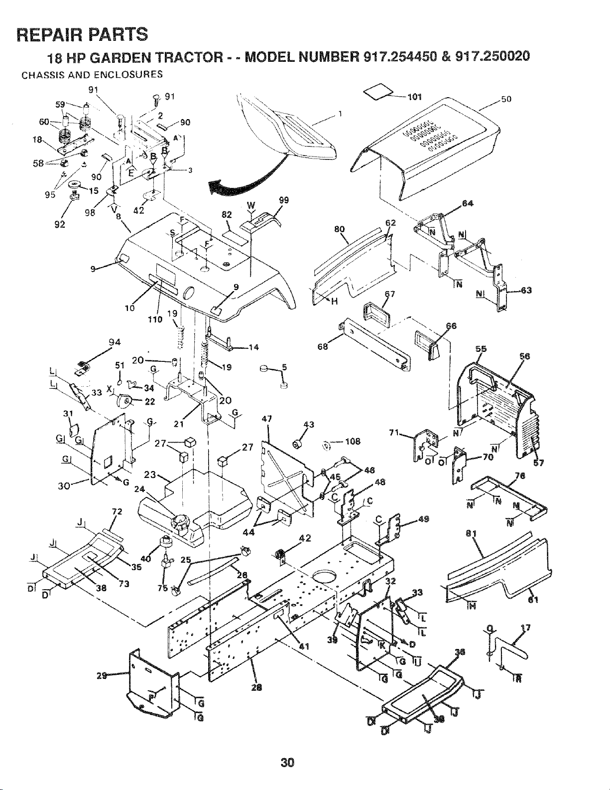
REPAIR PARTS
18 HP GARDEN TRACTOR - - MODEL NUMBER 9!7=254450 & 917.250020
CHASSIS AND ENCLOSURES
9t
_. 91
\
95 //_ 98
92
W
82
9g
8O
10
110
72
47
44
68
42
30
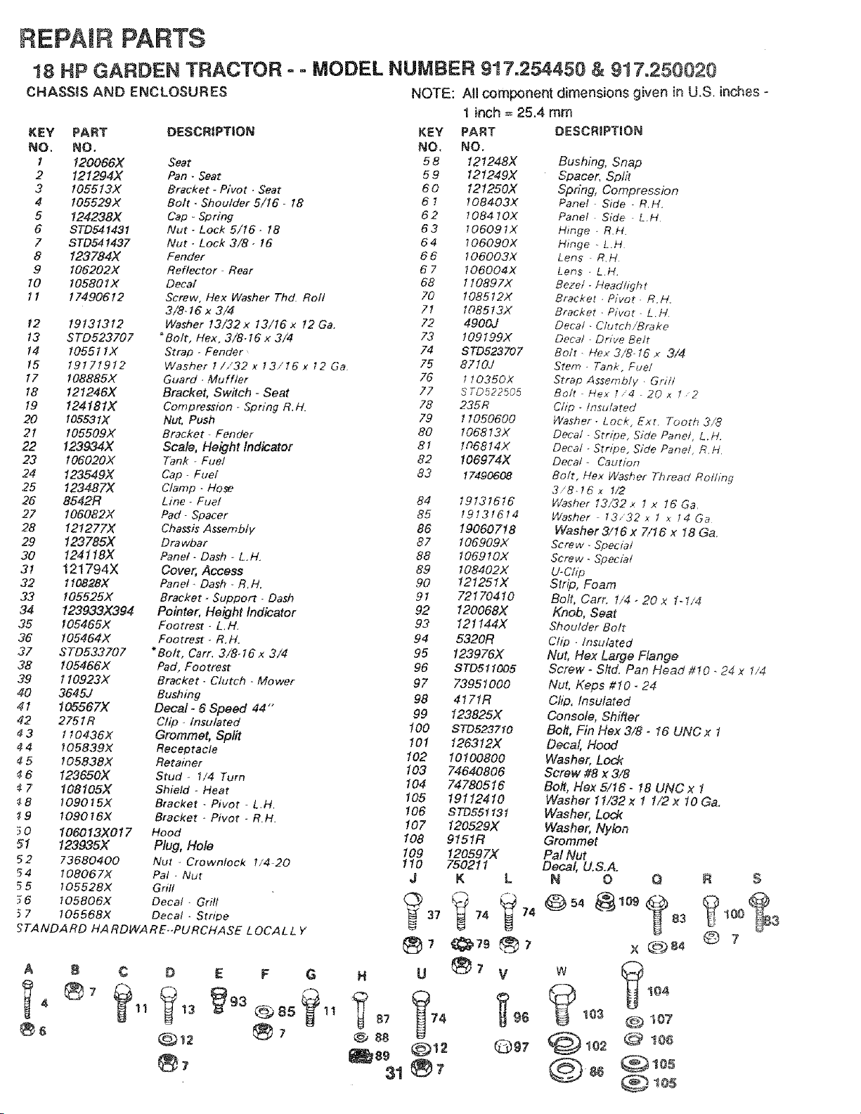
REPAIR PARTS
18 HP GARDEN TRACTOR ° = MODEL NUMBER 917.254450 & 9!7o250020
CHASSIS AND ENCLOSURES NOTE: All component dimensions given in U.S. inches-
KEY PART DESCRIPTION KEY
NO, NO. NO,
I 120066X Seat 5 8
2 121294X Pan - Seat 5 9
3 105513X Bracket _ Pivot - Seat 60
4 I05529X Bolt - Shoulder 5/16 - 18 6 !
5 124238X Cap * Spring 6 2
6 ST0541431 Nut- Lock 5/16- 18 6 3
7 STD541437 Nut - Lock 3/8- 16 64
8 123784X Fender 6 6
9 106202>( Reflector- Rear 6 7
10 I05801X Decal 68
tl 17490612 Screw. Flex Washer Thd. Roll 70
3/8-16 x 3/4 71
12 19131312 Washer 13/32x 13/t6x 12Ga. 72
13 ST0523707 _Bolt, Hex. 3/8-16x 3/4 73
t4 10551 IX Strap - Fender 74
15 19171912 Washer !/,'32 x 13/16x ;'2 Ga 75
17 108885X Guard. Muffler 76
18 121246X Bracket, Switch - Seat 77
19 I24181X Compression - Spring R.H. 78
20 105531X Nut, Push 79
21 105509X Bracket- Fender 80
22 123934X Scale, Height Indicator 81
23 I06020X Tank - Fuel 82
24 123549)( Cap- Fuel 83
25 123487X Clamp - Hose
26 8542R Line -Fuet 84
27 106082X Pad- Spacer 85
28 12127"7)( Chassis Assembly 86
29 123785X Drawbar 87
30 124118X Panel- Dash - L.H. 88
31 121794X Cover, Access 89
32 110828X Panel. Dash o R.H. 90
33 105525)( Bracket- Support- Dash 91
34 123933X394 Pointer, Height Indicator 92
35 105465X Footrest- L.H. 93
36 105464X Footrest. R.H. 94
37 STD533707 *Bolt, Cart. 3/&lB x 3/4 95
38 105466X Pad, Footrest 96
39 1 I0923X Bracket - Clutch - Mower 97
40 3645,/ Bushing 98
41 105567)( Decal- 6 Speed 44"" 99
42 2751R Clip - Insulated 100
3 110436X Grommet, Split 10!
4 4 105839X Receptacle 102
5 105838X Retainer 103
6 123650X Stud - 1/4 Turn 104
7 108105X Shield - Heat 105
_8 109015X Bracket o Pivot - L.H, 106
19 109016X Bracket - Pivot - R.H. 107
3 0 106013X017 Hood 108
51 123935X Plug, Hole 109
52 73680400 Nut - Crewnlock !/4_20 110
54 108067X Pal - Nut J
5 5 10552BX Grill
6 105806X Decal. Grill
7 I05568X Decal -Stnpe _ 37
_TANDARD HA RDWARE-PURCHASE LOCALL Y
®7
A B ¢ D E F G
®,
H U
87 74
@;, 88
al
1 inch = 25.4 mm
PART
NO.
121248X
12 t249)(
121250X
! o84o3x
!08410x
!06091X
1o6090x
o6o03x
106004x
110897X
108512x
1o85122:
4900J
109199x
STD523707
8710J
t t0350X
S T0522505
235R
1 !050600
106813X
106814X
106974X
17490608
19131616
19131614
19060718
t 06909X
1069!0X
108402X
t21251X
72170410
120068X
121 t44X
5320R
123976X
STD511005
73951000
4171R
123825X
ST0523710
126312X
10100800
74640806
7478O516
19112410
STDE51131
120529)(
9151R
12059 7X
750211
K L
_74 _ 74
,79
v
_96
Q97
DESCRIPTION
Bushing, Snap
Spacer, Split
Spring, Compression
Panel Side - R.H.
Panel Side L.H
Hinge . R.H.
Hinge L.H
Lens R.H
Lens - L H
Bezel - Head/i_h t
Bracket - Pivot. R.H.
Bracket . Pivot- L.H.
Decal • C/utch/Brake
Decal - Drive Bett
Bott• Hex 3/8-16 x 3/4
Stem. Tank, Fuel
Strap Assernblv . Grit!
Bo/t - Hex 7 4 -20x t 2
Clip. Insulated
Washer. Lock, Ext. Tooth 3/8
Decal - Stripe, Side Panel, L.H.
Decal ÷Stn_oe, Side Panel, R.H.
Decal- Caution
Bolt, Hex Washer Thread Rolling
3/8-16x 1/2
Washer 13/32 x ! x 16 Ga.
Washer 13,,'32 x 1 x 14 Ga
Washer 3/16 x 7/16 x 18 Ga.
Screw- Special
Screw- Special
U-Clip
Str#, Foam
Bolt, Carr. !/4 - 20 x 1-1/4
Knob, Seat
Shoulder Bolt
Ctip . Insulated
Nut, Flex Large Flange
Screw _ Sltd. Pan Head/€10 - 24 x 1/4
Nut, Keps 010 _ 24
Ch#. Insulated
Console, Shifter
Bolt, Fin Hex 3/8o 16 UNC x 1
Decal, Hood
Washer, Lock
Screw #8 x 3/8
Bolt, Hex 5/16.18 UNC x 1
Washer 11/32x 1 1/2x 10 Ga.
Washer, Lock
Washer, Nylon
Grommet
Pal Nut
Decal, U,S.A.
N 0 Q R S
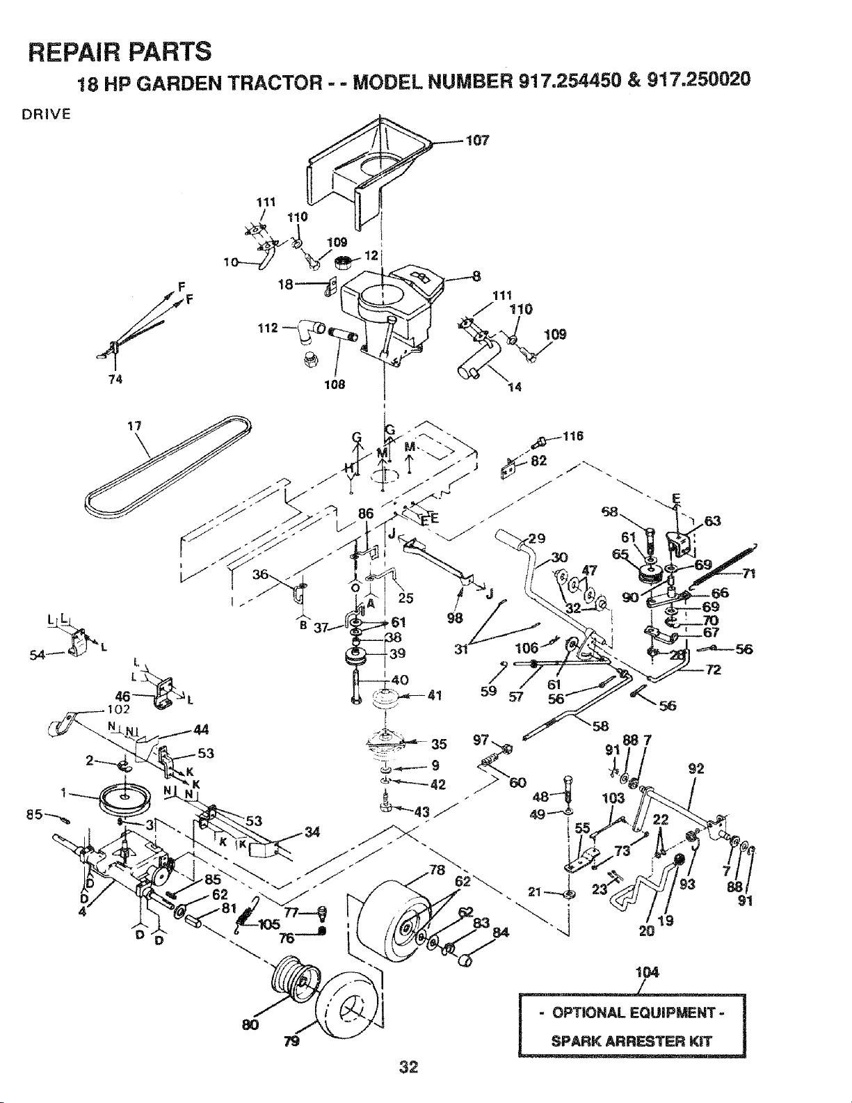
REPAIR PARTS
18 HP GARDEN TRACTOR - = MODEL NUMBER 917.254450 & 917.250020
DRIVE
F
74
111
1 tlo
108
D 0
32
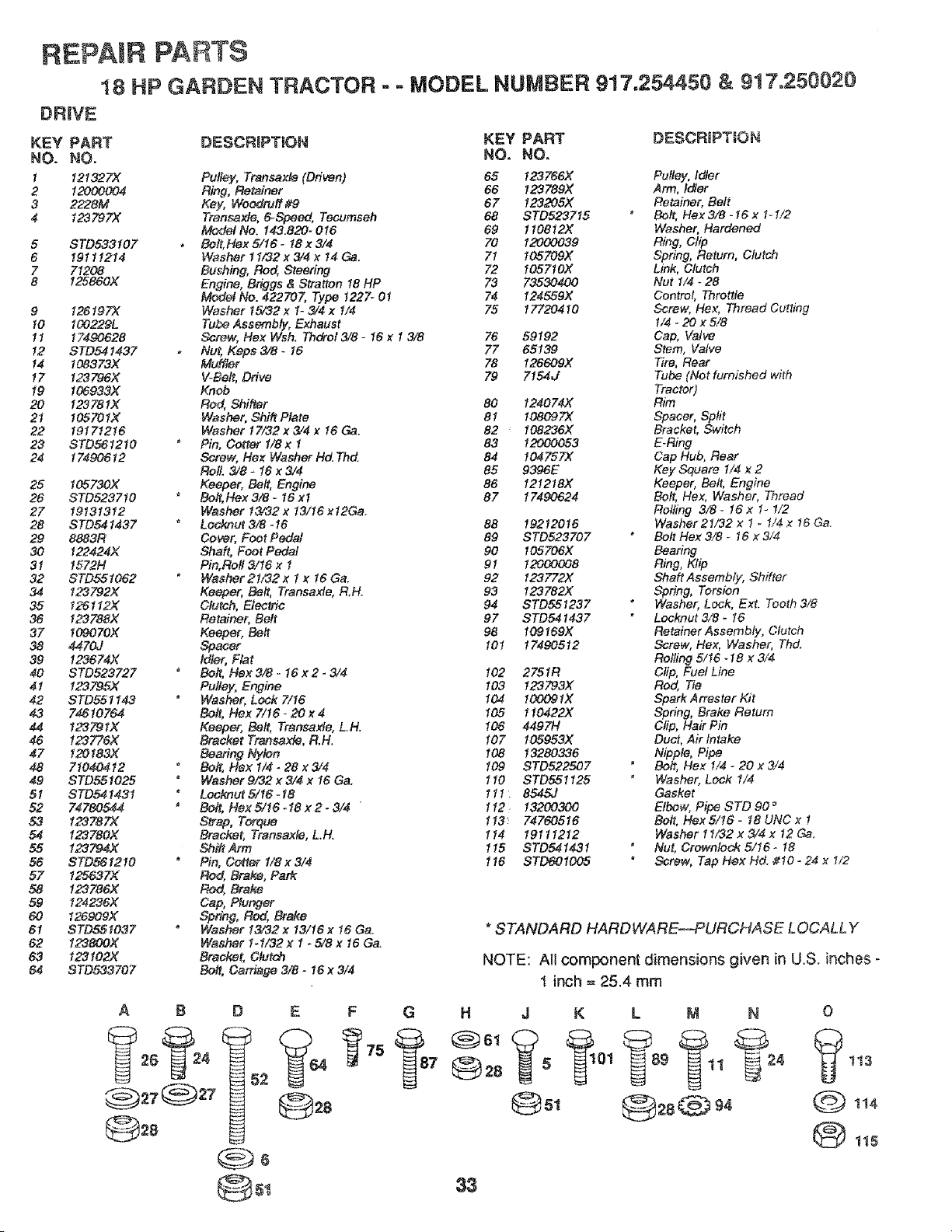
REPAIR PARTS
18 HP GARDEN TRACTOR ,. - MODEL NUMBER 917,254450 & 917.250020
DR_VE
KEY PART
NO. NO,
1 121327X
2 12000004
3 2228M
4 1232"97>(
5
6
7
8
STD533107
19111214
71208
125860X
9 126197X
10 100229L
11 17490628
12 STD541437
14 I08373X
17 123796X
19 106933)(
20 12378 IX
21 I05701X
22 19171216
23 STD561210
24 17490612
25 105730X
26 STD523710
27 19131312
28 STD541437
29 8883R
30 122424X
31 157214
32 STD551062
34 123792X
35 126112X
36 123788X
37 I09070X
38 44702
39 123674X
40 STD523727
41 123795X
42 STD551143
43 74[610764
44 123791X
46 123776X
47 120183X
48 71040412
49 STD551025
51 STD54143t
52 7,_780544
53 123787X
54 123780)(
55 123794X
56 STD561210
57 125637X
58 123786X
59 124236X
60 126909X
6I STD551037
62 123800X
63 123102X
64 STD533707
DESCRIPTION KEY PART DESCRIPTION
NO. NO,
Pulley, Transaxle (Driven) 65 123766X Pulley, idler
Ring, Retainer 66 123789X Arm, ldtar
Key, Weodruff 4'9 67 123205X Retainer, Belt
Transaxte, 6_Speed, Tecumseh 68 STD523715 * Bolt, Hex 3/8 - 16 x 1- I/2
Model No. 143.820- 016 69 110812X Washer, Hardened
Bett, Hex 5/16- 18 x 3/4 70 12000039 Ring, Ctip
Washer 11/32 x 3/4 x 14 Ga. 7I 105709X Spring, Return, Clutch
Bushing, Rod, Steering 72 105710X Link, Clutch
Engine, Briggs & Straiten 18 HP 73 73530400 Nut 1/4 * 28
Model No. 422707, Type 1227_ 01 74 124559X Centrot, Throttle
Washer 15/32 x 1-3/4 x 1/4 75 17720410 Screw, Hex, Thread Cutting
Tube Assembly, Exhaust 1/4 - 20 x 5/8
Screw, Hex Wsh. Thdrol 3/8 - 16 x 1 3/8 76 59192 Cap, Valve
Nu_, Keps 3/8- I6 77 65139 Stem, Valve
Muiller 78 126609X 7qre, Rear
V-Be#, Drive 79 7154J Tube (Not furnished with
Knob Tractor)
Rod, Shifter 80 124074)( Rim
Washer, Shi# Plate 81 108097% Spacer, Split
Washer 17/32x3/4 x 16 Ca. 82 108236X Bracket, Switch
Pin, Cotter I/8 x 1 83 12000053 E.Ring
Screw, Hex Washer ltd. Thd. 84 I04757X Cap Hub, Rear
Rol!. 3/8 - 16 x 3/4 85 9396E Key Square 1/4 x 2
Keeper, Bolt, Engine 86 121218X Keeper, Belt, Engine
Bolt, Hex 3/8- 16xl 87 17490624 Bolt,/Vex, Washer, Thread
Washer t3/32 x 13/16 x12Ga. Rolling 3/8 * 16 x 1- 1/2
Leeknut 3/8-16 88 19212016 Washer 21/32 x 1 _ I/4x 16 Ga.
Cowr, Feet Pedal 89 STD523707 Bolt Hex 3/8 _ 16 x 3/4
Shaft, Foot Pedal 90 105706X Bearing
Pin, Roll 3/t6 x 1 91 12000008 Ring, Ktip
Washer 21/82 x I x 16 Ga. 92 123772X Shaft Assembfy, Shifter
Keeper, Bolt, Transaxle, R,H. 93 123782X Spring, Torsion
Clutch, Electric 94 STD551237 Washer, Lock, Ext. Tooth 3/8
Retainer, Belt 97 STD541437 Locknut 3/8 - t6
Keeper, Be# 98 109!69X Retainer Assernbly, Clutch
Spacer 101 17490512 Screw, Hex, Washer, Thd.
Idler, Fiat Roiling 5/t6-18 x 3/4
Bolt, Hex 3/8 - 16 x 2 - 3/4 102 2751R Clip, Fuel Line
Pulley, Engine 103 !23793X Rod, Tie
Washer, Lock 7/16 104 100091X Spark Arrester Kit
Bolt, Rex 7/16-20x4 105 110422X Spring, Brake Return
Keeper, Be#, Transaxle, LH. 106 4497H Clip, Hair Pin
Bracket Transaxle, R.H. 107 105953X Duct, Air Intake
Bearing Nylon 108 13280336 Nipple, Pipe
Be#, Hex 1/4 _ 28 x 3/4 109 STD522507 Bolt, Hex 1/4 - 20 x 3/4
Washer g/32 x 3/4 x I6 Ga. 110 STD551125 * Washer, Lock 1/4
Lock,nut 5/16 - 18 1 t I : 8545J Gasket
Be& Hex S/16-18 x 2- 3/4 ' 112 13200300 Elbow, Pipe STD 90 °
S_r_o, Torque 113: 74760516 Be& Hex S/16 - 18 UNC x !
Bracket, Transaxle, L.H. 114 19111212 Washer11/32 x 3/4 x12 G&
Shift Arm 1t5 STD541431 Nut, Crewnfock S/16- 18
Pin, Cotter 1/8 x 3/4 116 STD601005 Screw, Tap Hex Hd. #t0 - 24 x 1/2
Rod, Brake, Park
Rod, Brake
Cap, Plunger
Spring, Rod,, Brake
Washer 13,'32 x 13/16 x 16 Ga_ * STANDARD HARDWARE--PURCHASE LOCALLY
Washer 1_1/32 x 1 - 5/8 x 16 Ga.
Brad{et,C/u_ch NOTE: Art component dimensions given in U,S. inches -
Bolt, Carriage 3/8 - 16 x 314
I inch = 25.4 mm
A B D E F G H J
@=8
33
K L M N O
© ,,,
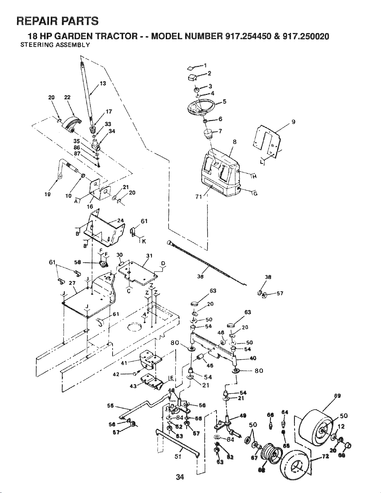
REPAIR PARTS
18 HP GARDEN TRACTOR - = MODEL NUMBER 917.254450 & 917,250020
STEERING ASSEMBLY
\
\
\
\
\
\
19
61
10
• 24 61
3O
3t
\
13
_7
51
5O
38
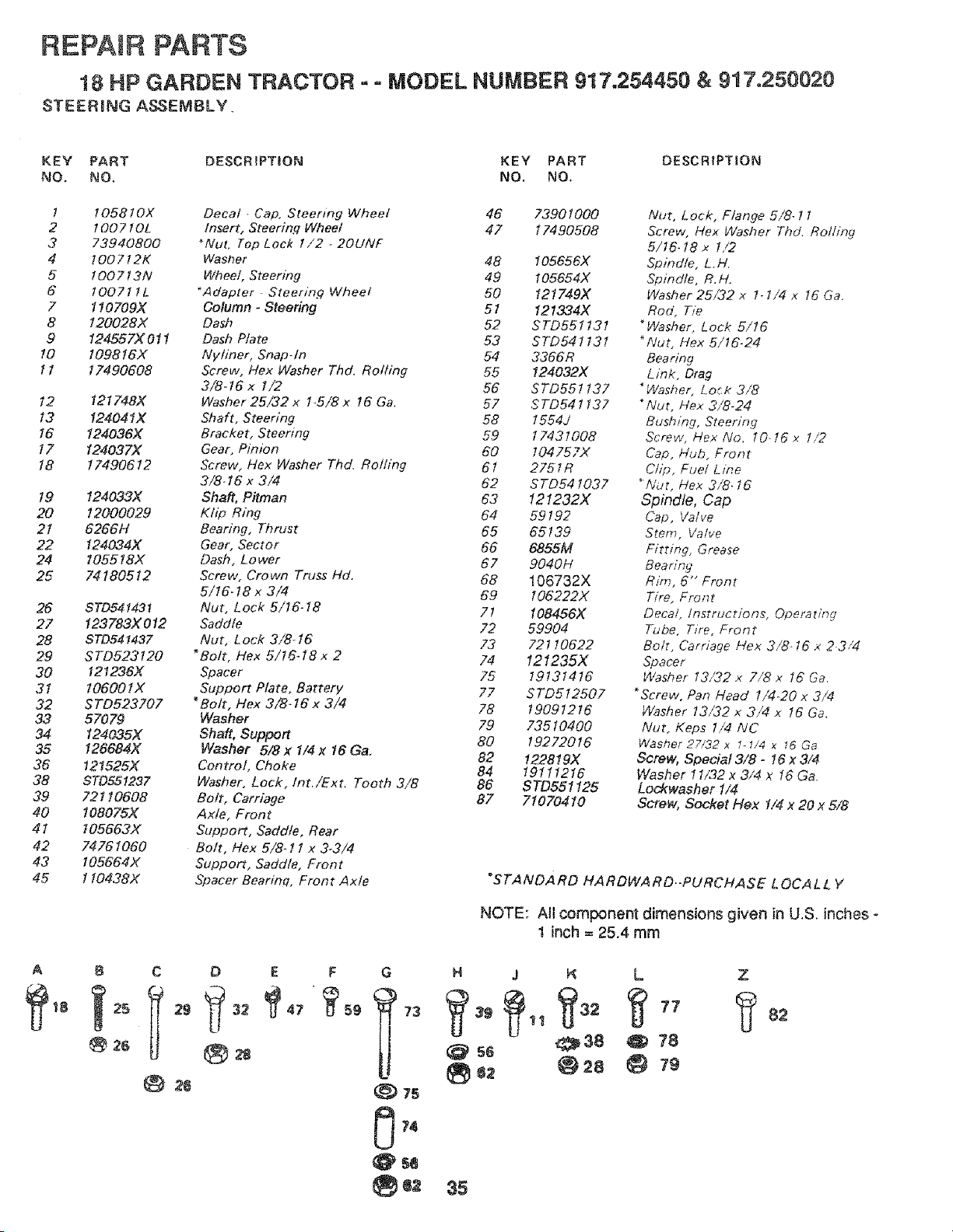
REPAIR PARTS
18 HP GARDEN TRACTOR = = MODEL NUMBER 917.254450 & 917.250020
STEERmNG ASSEMBLY.
KEY PART DESCRIPTION KEY PART DESCRtPTION
NO. NO, NO. NO.
l 105810X Decal - Cap, Steemng Wheel 46 73901000
2 !007 IOL Insert, Steerinfl Wheel 47 17490508
3 73940800 _Nut, Top Lock 1/2 _20UNF
4 100712K Washer 48 105656>(
5 1007!3N Wheel, Steering 49 105654X
6 100711L *Adapter Steering Wheel 50 121749X
7 110709X Column - Steering 51 121334X
8 120028X Dash 52 STD551131
9 124S57X011 Dash Plate 53 STD541131
10 109816X Ny/iner, Snap-In 54 3366R
11 17490608 Screw, Hex Washer Thd. Rolling 55 124032X
3/8-16x 1/2 56 STD551137
t2 121748)( Washer 25/32 x 1-5/8x 16 Ga. 57 STD541137
13 124041X Shaft, Steering 58 1554J
16 124036X Bracket, Steering 59 17431008
17 124037>( Gear, Pinion 60 I04757X
18 17490612 Screw, Hex Washer Thd. Roiling 6t 2751R
3/8-16x 3/4 62 STD541037
19 124033>( Shaft, Pitman 63 121232X
20 12000029 Kh_o Ring 64 59192
2I 6266H Bearing, Thrust 65 65139
22 124034X Gear. Sector 66 6855M
24 105518)< Dash, Lower 67 9040H
25 74180512 Screw, Crown Truss Hd. 68 106732X
5/16-18x 3/4 69 106222X
26 STD541431 Nut, Lock 5/16-18 71 108456X
27 123783X012 Saddle 72 59904
28 STD541437 Nut, Lock 3/8-16 73 72! 10622
29 STD523120 *Bolt, Hex 5/16.18 x 2 74 121235X
30 121236)( Spacer 75 19131416
31 106001X Support Plate, Battery 77 STD5!2507
32 STD523707 *Bolt, Hex 3/8-16x 3/4 78 19091216
33 57079 Washer 79 73510400
34 124035X Shaft, Support 80 19272016
35 126684X Washer 5/8x 1/4x 16 Ga, 82 122819X
36 121525X Control, Choke 84 19111216
38 STD551237 Washer, Lock,/nt,/Ext. Tooth 3/8 86 STD551125
39 72110608 Bolt, Carriage 87 7107"0410
40 108075>( Axle, Front
41 105663X Support, Saddle, Rear
42 74761060 Bolt, Hex 5/8-11 x 3-3/4
43 105664X Support, Saddle, Front
45 110438)( Spacer Bearinq, Front Axle
A B C D E F
®2s
26
Nut, Lock, Flange 5/8- ! 1
Screw, Hex Washer Thd. Roiling
5/t6- I8 x I,/2
Spindle, L, H,
Spindle, R, H,
Washer 25/32 x 1-1/4 x 16 Ga,
Rod, Tie
*Washer, Lock 5/16
"/Vut, Hex 5/16-24
Bearing
Link, Drag
*Washer, Lo_K 3/8
*Nut, Hex 3/8-24
Bushing, Steering
Screw, Hex No. 10-16x 1/2
Cap, Hub, Front
Clip, Fuel Line
"Nut, Hex 3/8. 16
Spindle, Cap
Cap, Valve
Stem, Valve
Fitting, Grease
Bearing
Rim, 6" Front
Tire, Front
Decat_ Instructions, Operating
Tube, Tire, Front
Bolt, Carriage Hex 3/8-16 x 2 3/4
Spacer
Washer 13/32 x 7/8 x 16 Ga,
*Screw. Pan Head 1/4-20 x 3/4
Washer 13/32 x 3/4 x I6 Ga,
Nut. Keps 1/4 /VC
Washer 27/32 x I-1/4 x 16 Ga
Screw, Special 3/8 - I6 x 3/4
Washer ! 1/32 x 3/4 x 16 Ga.
Lockwasher 1/4
Screw, Socket Flex 1/4 x 20 x 5/8
"STANDARD HARDWARD..PURCHASE LOCALL Y
NOTE: All component dimensions given in U.S. inches -
1 inch = 25.4 mm
G N j K L Z
@SO .z&_38 @ 7'8
@ 75
35
82
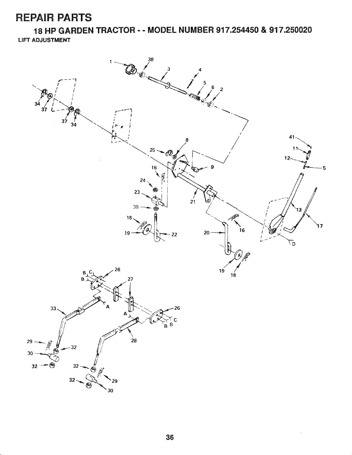
REPAIR PARTS
18 HP GARDEN TRACTOR - - MODEL NUMBER 917.254450 & 917,250020
UFT ADJUSTMENT
34
37
34
B C 26
32 _ __[f" "_" 29
21 "
20 16
!8
_5
36
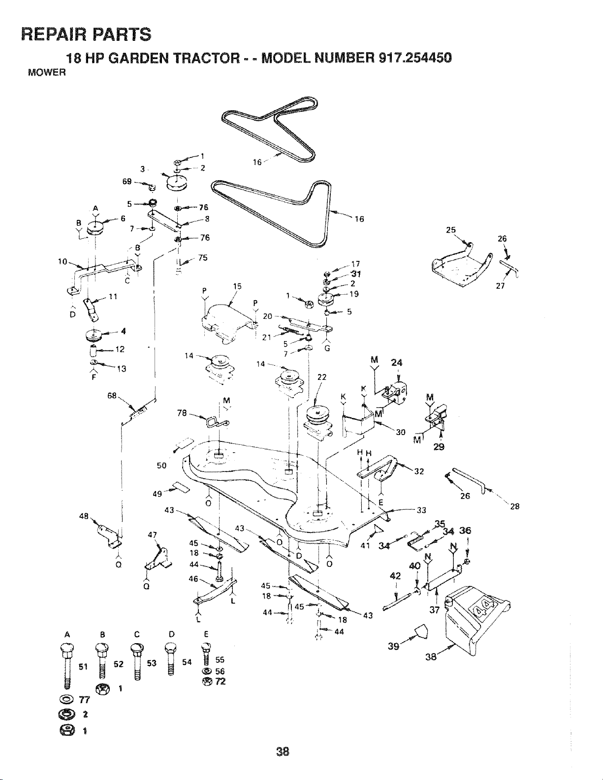
REPAIR PARTS
MOWER18HP GARDEN TRACTOR ° - MODEL NUMBER 917.254450
5O
25
Q
A B
_51 ?52
77
O
47
L
C D
58
_7"Z
45
44
41
E
33
26
26
27
" 28
38
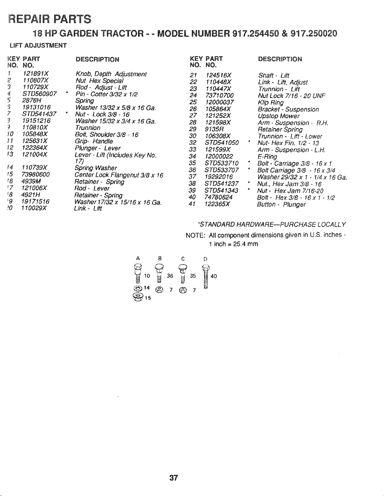
REPAIR PARTS
18 HP GARDEN TRACTOR - o MODEL NUMBER 917.254450 & 917.250020
LIFT ADJUSTMENT
k<EY PART DESCRIPTION KEY PART
NO. NO. NO, NO.
1 121891X Knob, Depth Adjustment 21 t24516X
2 110807X Nut Hex Special 22 110448X
3 t 10729X Rod - Adjust - Lift 23 110447X
4 STD560907 * Pin - Cotter 3/32 x 1/2 24 73710700
5 2876H Spring 25 12000037
19131016 Washer 13/32 x 5/8 x 16 Ga. 26 I05864X
7 STD541437 * Nut- Lock 3/8 - 16 27 121252X
19151216 Washer 15/32 x 3/4 x 16 Ga. 28 121598X
? 1108IOX Trunnion 29 9135R
! O 105848X Bolt, Shoulder3/8- 16 30 106308X
11 125631X Grip- Handle 32 STD541050
12 !22364X Plunger- Lever 33 121599X
13 t21004X Lever - Lift (Includes Key No. 34 12000022
17) 35 STD533710
_4 110739X Spring Washer 36 STD533707
_5 73980600 Center Lock Flangenut 3/8 x 16 37 19292016
_6 4939M Retainer- Spring 38 STD54!237
!7 121006X Rod- Lever 39 STD541343
_8 4921H Retainer- Spring 40 74780624
'9 19171516 Washer17/32 x 15/16x 16 Ga. 41 122365X
?0 110029X Link - Lift
DESCRIIPTJON
Shaft- Lift
Link- Lift, Adjust
Trunnion- Lift
Nut Lock 7/I6 - 20 UNF
Kfip Ring
Bracket- Suspension
Upstop Mower
Arm - Suspension - R.H.
Retainer Spring
Trunnion - Lift - Lower
Nut- Hex Fin. 1/2 - 13
Arm - Suspension - L.H.
E-Ring
Bolt - Carriage 3/8 - t6 x 1
Bolt Carriage 3/8 - 16 x 3/4
Washer 29/32 x 1 - 1/4 x 16 Ga.
Nut., Hex Jam 3/8- 16
Nut - Hex Jam 7/16-20
Bolt- Hex 3/8- 16 x 1 - 1/2
Button- Plunger
"STANDARD HARDWARE--PURCHASE LOCALLY
NOTE: All component dimensions given in U.S. inches -
1 inch = 25.4 mrn
A B C D
14©7Q7
37
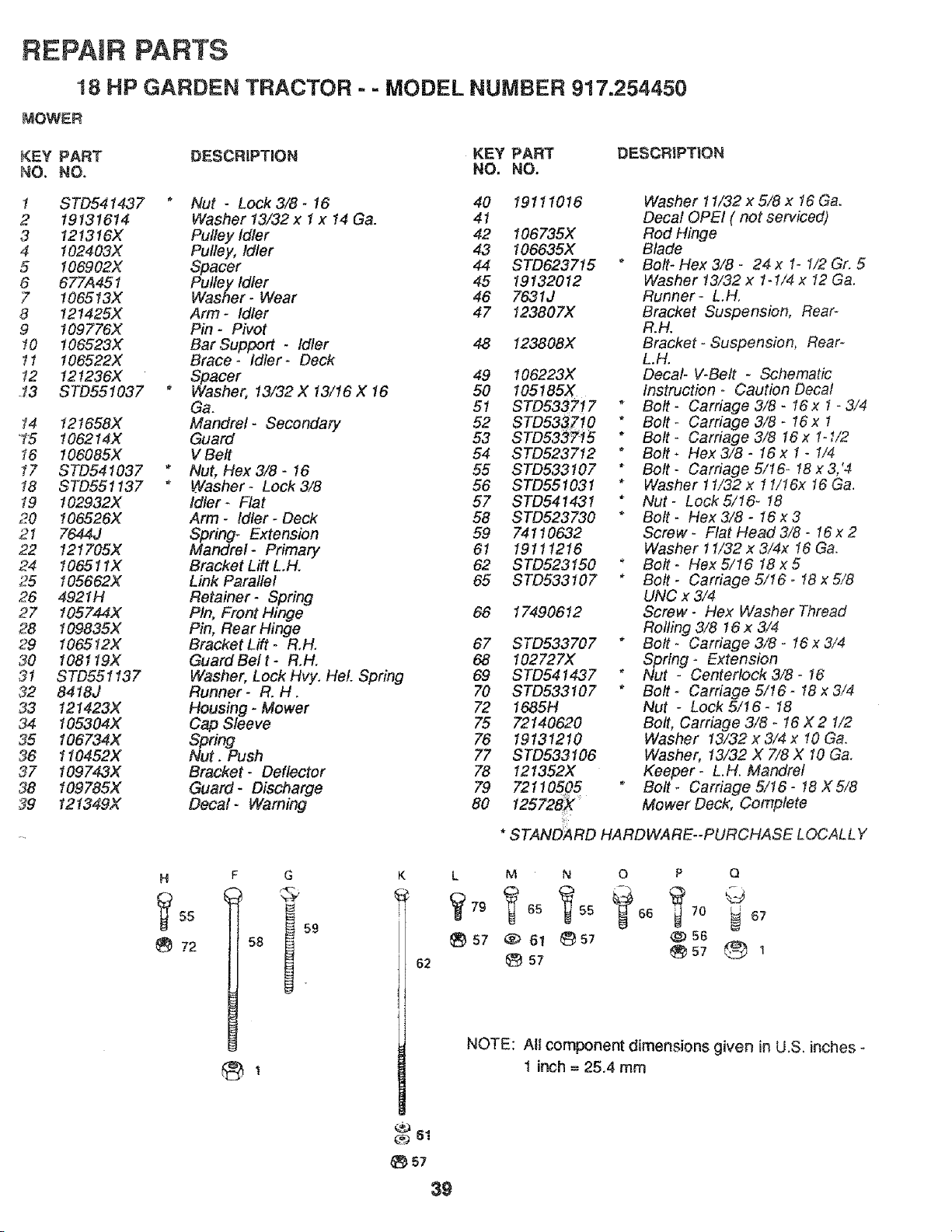
REPAIR PARTS
18 HP GARDEN TRACTOR = - MODEL NUMBER 917.254450
MOWER
KEY PART DESCRiPTiON KEY PART
NO. NO. NO, NO.
1 STD541437 *
2 19131614
3 121316X
4 102403X
5 I06902X
6 677A451
7 106513X
8 121425X
9 !09776X
10 106523X
11 106522X
12 t21236X
._3 STD551037 *
14 121658)(
_15 106214X
!6 106085X
17 STD54 t037
18 STD551137
19 I02932X
20 106526X
21 7644J
22 121705X
24 106511X
25 105662X
26 4921H
27 105744X
28 t09835X
29 106512X
30 108119X
3t STD551137
32 8418J
33 121423X
34 I05304X
35 106734X
36 110452X
37 109743X
38 109785X
39 t21349X
Nut - LOCk3/8- 16 40 19111016
Washer 13/32x 1 x t4 Ga. 41
Pulley Idler 42 106735X
Pulley, Idler 43 I06635X
Spacer 44 STD623715
Pulley Idler 45 19132012
Washer- Wear 46 7631J
Arm- Idler 47 123807X
Pin- Pivot
Bar Support - Idler 48 123808X
Brace- Idler- Deck
Spacer 49 t06223X
Washer, 13/32 X 13/16 X 16 50 I05!85X
Ga. 51 STD5337!7
Mandrel- Secondary 52 STD5337t0
Guard 53 STD5337_5
V Belt 54 STD523712
Nut, Hex 3/8 - 16 55 STD533107
Washer- Lock 3/8 56 STD551031
Idler_ Flat 57 STD541431
Arm - Idler - Deck 58 STD523730
Spring- Extension 59 74110632
Mandrel- Primary 61 19111216
Bracket Lift L.H. 62 STD523150
Link Parallel 65 STD533107
Retainer- Spring
Pin, Front Hinge 66 174906 I2
Pin, Rear Hinge
Bracket Lift - R.H. 67 STD533707
GuardBelt- R.H. 68 102727X
Washer, Lock Hvy. HeL Spring 69 STD541437
Runner- R. H. 70 STD533!07
Housing - Mower 72 1685H
Cap Sleeve 75 72140620
Spring 76 19131210
Nut. Push 77 STD533106
Bracket- Deflector 78 121352X
Guard - Discharge 79 721!0505
Decal- Warning 80 I25728X _
DESCRIPTION
Washer 11/32 x 5/8 x 16 Ga.
Decal OPEl ( not serviced)
Rod Hinge
Blade
* Bolt- Hex 3/8 - 24 x 1- 1/2 Gr. 5
Washer 13/32 x 1-1/4 x 12 Ga.
Runner- L.H.
Bracket Suspension, Rear-
R.H.
Bracket - Suspension, Rear-
L.H.
Decal- V-Belt - Schematic
Instruction - Caution Decal
* Bolt - Carriage 3/8 - 16 x 1- 3/4
* Bolt - Carriage 3/8 - 16 x t
* Bolt Carriage 3/8 16 x 1oI/2
* Bolt _ Flex 3/8 o 16 x 1 - 1/4
* Bolt- Carriage5/16- 18x3,'4
* Washer 11/32 x 1 !/16x I6 Ga.
* Nut - Lock 5/16- !8
* Bolt- Hex3/8- 16x3
Screw - Flat Head 3/8- 16 x 2
Washer 11/32 x 3/4x 16 Ga.
" Bolt- Hex5/16 18x5
* Bolt - Carriage 5/16 - t8 x 5/8
UNC x 3/4
Screw - Flex Washer Thread
Rolling 3/8 16 x 3/4
* Bolt - Carriage 3/8 - 16x 3/4
Spring- Extension
* Nut - Centertock 3/8 - 16
* Bolt - Carriage 5/16 - 18 x 3/4
Nut - Lock 5/16- 18
Bolt, Carriage 3/8 - 16 X 2 1/2
Washer 13/32 x 3/4 x !0 Ga.
Washer, 13/32 X 7/8 X 10 Ga.
Keeper- L.H. Mandrel
Bolt_ Carriage5!16- 18X5/8
Mower Deck, Complete
* STANDARD HARDWARE--PURCHASE LOCALLY
H
5s
72
F
l
G
62
L M N O P Q
57 ®61 _57 @56
57
NOTE: All component dimensions given in U.S. inches _
t inch = 25.4 mm
57
39
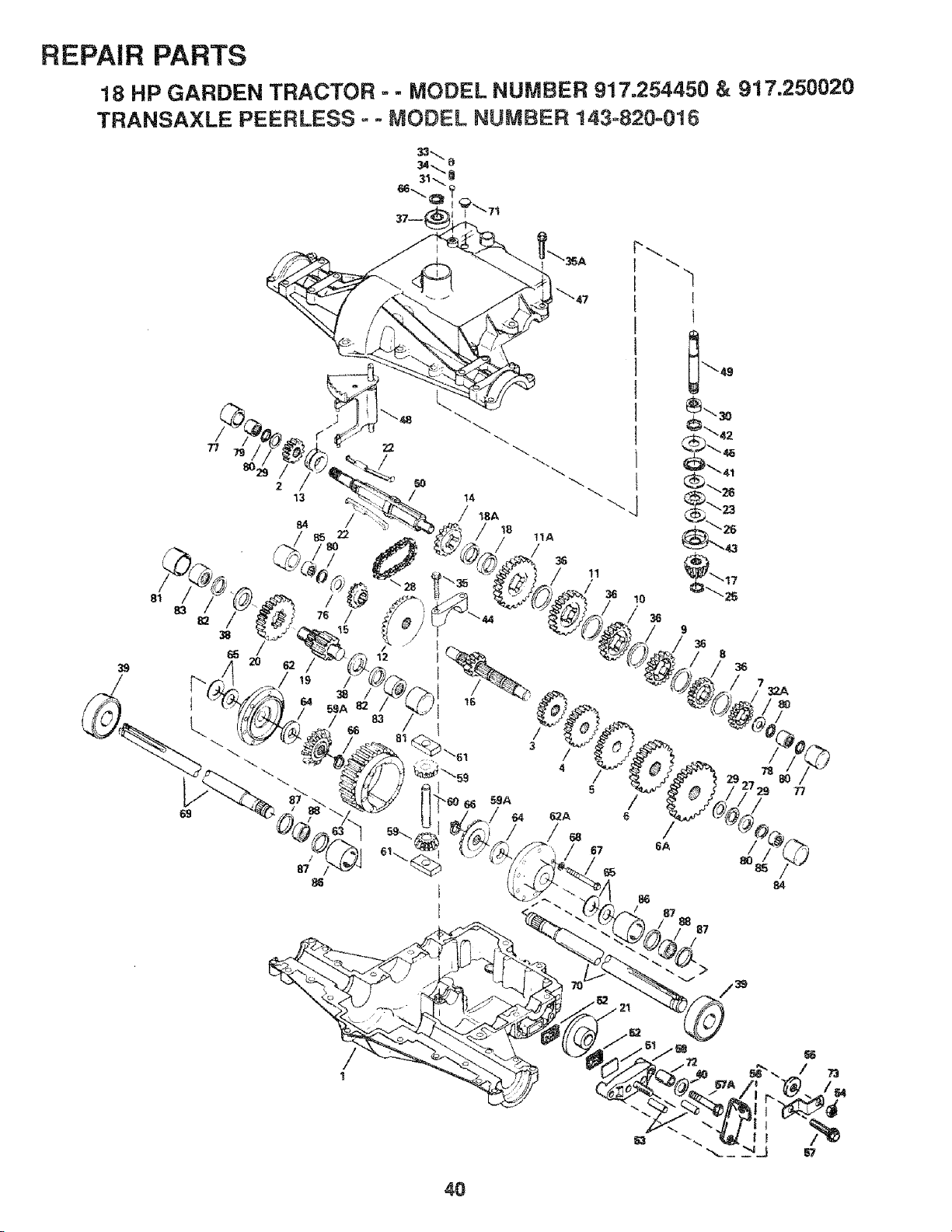
REPAIR PARTS
18 HP GARDEN TRACTOR - - MODEL NUMBER 917.254450 & 917.250020
TRANSAXLE PEERLESS o - MODEL NUMBER 143-820-016
39
77 22
/
87
E
11A
36
7'8
5
/ /
6
/
67 8A /
80
32A
77
84
/
1
40
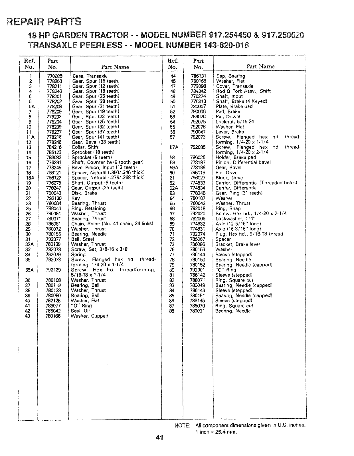
REPAIR PARTS
!8 HP GARDEN TRACTOR - - MODEL NUMBER 917.254450 & 917o250020
TRANSAXLE PEERLESS-= MODEL NUMBER 143-820-e16
Part
No.
7700_
778253
778211
778240
778_)01
_8202
775203
7782O4
778239
7782O7
778216
778246
784216
786123
786082
776291
778245
786121
786122
776275
778247
7£0843
792138
780084
78804O
780051
78007t
786081
780072
780155
792077
780139
792078
792079
792073
792129
780108
780119
780128
780050
792128
788077
788042
780166
Part Name
Case, Transaxle
Gear, Spur (15 teeth)
Gear, Spur (12 teeth)
Gear, Spur (18 teeth)
Gear, Spur (25 teeth)
Gear, Spur (28 teeth)
G_t_r, Spur (31 teeth)
Gear, Spur (19 teeth)
Gear, Spur (22 teeth)
Gear, Spur (25 teeth)
Gear, Spur (32 teeth)
Gear, Spur (37 teeth)
Gear, Spur (41 teeth)
Gear, Bevef (33 teeth)
Collar, Shift
Sprocket ( 18 teeth)
Sprocket 19 teeth)
Shaft, Counter (w/9 tooth gear)
Bevel Pinion, Input (13 teeth)
Spacer, Neturaf 1_350/.340 thick)
Spacer, Natural (.275/,268 thick)
Shaft, Output (9 teeth)
Gear, Output (35 teeth)
Disk, {3rake
Key
Bearing, Thrust
Ring, Retaining
WaSher, Thrust
Bearing, Thrust
Chain, Roller (No. 41 chain, 24 links)
Washer, Thrust
Bearing, Needle
Ball, Steel
Washer, Thrust
Screw, Set, 3/8-16 x 3/8
Spring
Screw, Flanged hex hd. thread-
forming, I/4-20 x 1-1/4
Screw, Hex hd. threadforming,
5/16-18 x 7-1/4
Washer, Thrust
Bearing, Ball
Washer, Thrust
Bearing, Ba_I
Washer, Rat
"O" Ring
Seal, Oil
Washer, Cupped
Ref.
NO.
44
45
47
48
49
50
51
52
53
54
55
57A
g
72
73
78
g
Part
No. Pa_ Name
I
788131
7887_
772O98
784342
775274
775313
790007
790006
786026
792075
790047
792073
792085
790025
778197
778198
786019
786027
774833
774834
778248
780107
780042
792018
792020
792006
774832
774831
792074
788067
786086
780153
788144
780150
780152
792001
786142
788O71
780049
786143
780151
786145
788070
780031
Cap, Bearing
Washer, Flat
Cover, Transexle
Rod 8 Fork Assy,, Shift
Shaft, Input
Shaft, Brake (4 Keyed)
Prate, Brake pad
Pad, Brake
Pin, Dowel
Locknut, 5It6-24
Washer, Flat
Lever, Brake
Screw, Flanged hex hd. thread-
forming, f/4-20 x 1-1/4
Screw, Flanged hex hd. thread-
forming, 114-20 x 2_1!4
Holder, Brake pad
Pinion, Differential bevel
Gear, Bevel
Pin, Drive
B(eck, Drive
Carrier, Differential (Threaded holes)
Carrier, Differential
Gear, Ring (31 teeth)
Washer
Washer, Thrust
Ring, Snap
Screw, Hex hd., t/4-20 x 2-1/4
Lockwasher, 1/4"
Axle I12-5/!6" _ong)
Axle 116-3/16" long)
Plug, Hex hd., 9/16-18 thread
Spacer
Bracket, Brake lever
Washer
Sleeve (stepped)
Bearing, Needle
Bearing, Needte (capped)
"O" Ring
Sleeve {stepped)
Ring, Square cut
Bearing, Needle (capped)
Sleeve (stepped)
Beat_ng, Needle (capped)
Sleeve (stepped)
Ring, Square cut
Bearing, Needle
NOTE: All component dimensions given in U.S. inches.
I inch = 25.4 ram.
4!
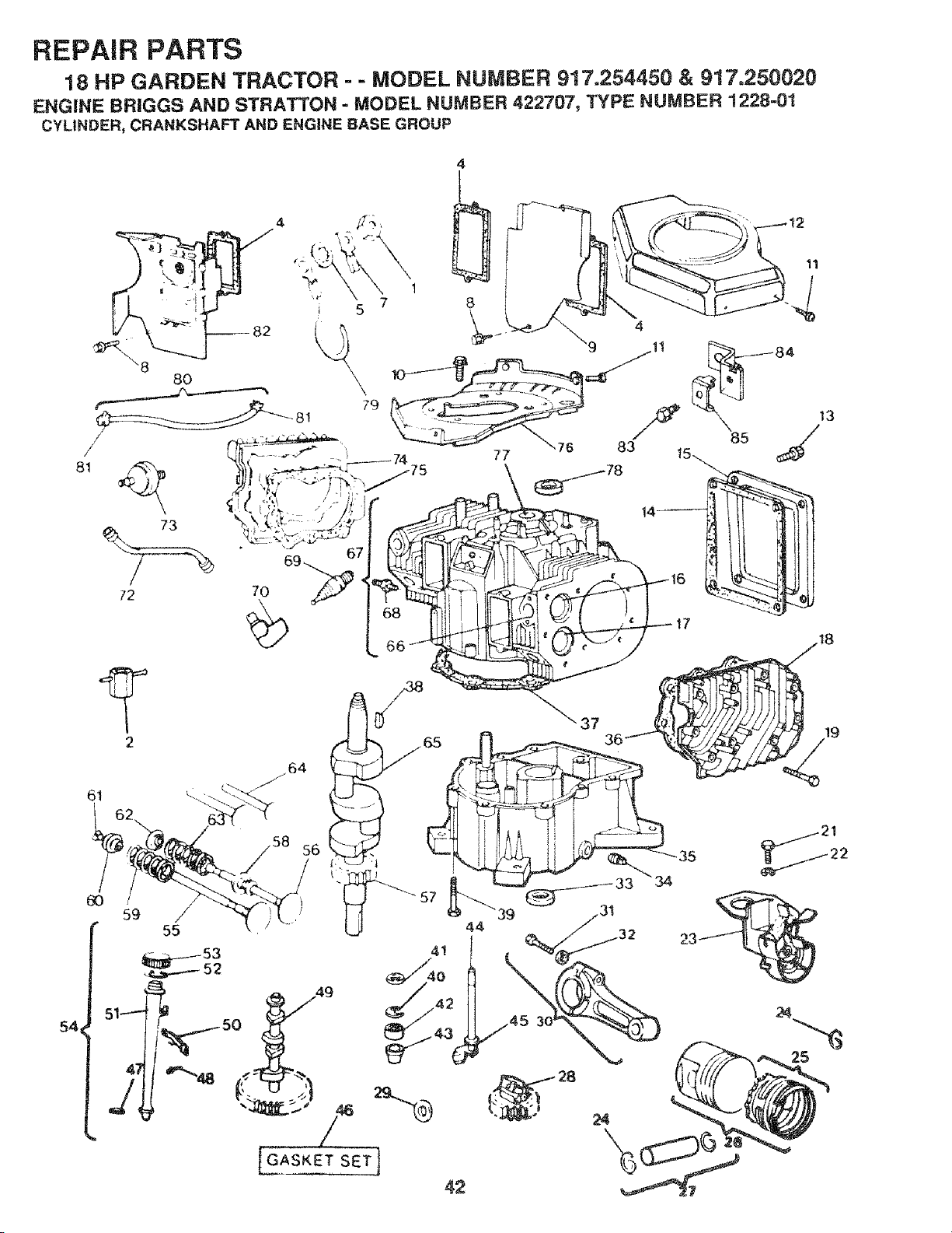
REPAIR PARTS
18 HP GARDEN TRACTOR - - MODEL NUMBER 917.254450 & 917.250020
ENGINE BRIGGS AND STRATTON - MODEL NUMBER 422707, TYPE NUMBER 1228-01
CYLINDER, CRANKSHAFT AND ENGINE _ASE GROUP
81
54
_\8
8O
72
t
4
5 7 8
//t8
24
19
/
21
25
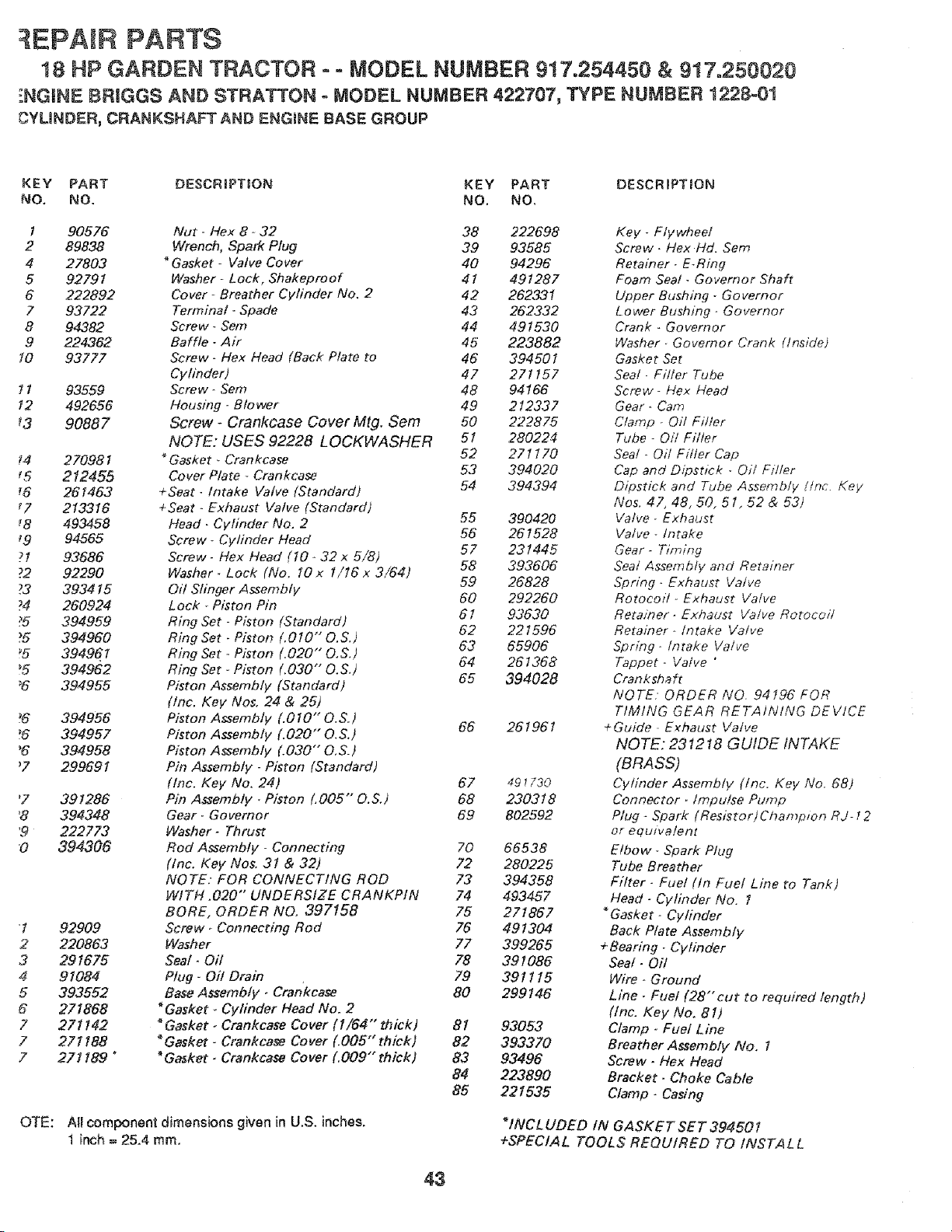
: EPAIR PARTS
18 HP GARDEN TRACTOR ° - MODEL NUMBER 917.254450 & 917.250020
_NGINE BRIGGS AND STRATTON = MODEL NUMBER 422707, TYPE NUMBER 1228=01
CYLINDER, CRANKSHAFT AND ENGINE BASE GROUP
KEY PART DESCRIPTION KEY PART DESCRIPTION
NO, NO. NO. NO,
I 90576
2 89838
4 27803
5 92791
6 222892
7 93722
8 94382
9 224362
t0 93777
! 1 93559
12 492656
_3 90887
_4 270981
_5 212455
_6 261463
r7 213316
',8 493458
9 94565
?1 93686
?2 92290
73 393415
74 260924
_5 394959
75 394960
_5 39496.1
_5 394962
_6 394955
>.6 394956
'6 394957
'6 394958
_7 299691
'7 391286
'8 394348
'9 222773
0 394306
'1
2
3
4
5
6
7
7
7
OTE:
92909
220863
291675
91084
393552
271868
27! 142
27t 188
271189 "
Nut - Flex 8 - 32
Wrench, Spark Plug
Gasket - Valve Cover
Washer - Lock, Shakeproof
Cover - Breather Cylinder No. 2
Terminal- Spade
Screw- Sem
Ba rite - Air
Screw- Flex Head (Back Plate to
Cylinder)
Screw- Sem
Housing - Blower
Screw- Crankcase Cover Mtg. Sere
NOTE: USES 92228 LOCKWASHER
* Gasket - Crankcase
Cover Plate - Crankcase
+Seat- Intake Valve (Standard)
+Seat - Exhaust Valve (Standard)
Head - Cylinder No, 2
Screw- Cylinder Head
Screw- Flex Head (10- 32 x 5/8)
Washer- Lock (No. 10 x 1/16 x 3/64)
Oil Slinger Assembly
Lock - Piston Pin
Ring Set - Piston (Standard)
Ring Set - Piston (.010"0.S.
Ring Set - Piston (,020" O,S.
Ring Set - Piston (.030" O.S.
Piston Assembly (Standard)
(Inc. Key Nos, 24 & 25)
Piston Assembly (.010" O.S.
Piston Assembly (.020" O,S.
Piston Assembly (.030" O,S.
Pin Assembly - Piston (Standard)
(Inc. Key No. 24)
Pin Assembly _ Piston (.005"" O.S.)
Gear- Governor
Washer- Thrust
Rod Assembly - Connecting
(Inc. Key Nos. 31 & 32)
NOTE: FOR CONNECTING ROD
WITH .020"" UNDERSIZE CRANKPIN
BORE, ORDER NO. 397158
Screw _ Connecting Rod
Washer
Seal- Oil
Plug- Oil Drain
Base Assembly. Crankcase
*Gasket. Cylinder Head No. 2
"Gasket- Crankcase Co vet ( 1/64" th ic k)
"Gasket- Crankcase Cover (.005" thick)
"Gasket- Crankcase Cover (.009" thick)
All component dimensions given in U,S. inches,
1 inch = 25.4 ram.
38 222698
39 93585
40 94296
41 491287
42 262331
43 262332
44 491530
45 223882
46 394501
47 271157
48 94166
49 212337
50 222875
51 280224
52 271170
53 394020
54 394394
55 390420
56 261528
57 231445
58 393606
59 26828
60 292260
61 93630
62 221596
63 65906
64 261368
65 394028
66 261961
67 49_30
68 230318
69 802592
70 66538
72 280225
73 394358
74 493457
75 271867
76 491304
77 399265
78 391086
79 391115
80 299146
81 93053
82 393370
83 93496
84 223890
85 221535
Key- Flywheel
Screw- Hex Hd. Sem
Retainer- E-Ring
Foam Seal - Governor Shaft
Upper Bushing - Governor
Lower Bushing _ Governor
Crank - Governor
Washer _ Governor Crank (Inside)
Gasket Set
Sea! - Filler Tube
Screw- Hex Head
Gear- Cam
Clamp - Oit Filler
Tube - Oil Filler
Seal - Oil Filler Cap
Cap and Dipstick _ Oil F/tier
Dipstick and Tube Assembly !tnc. Key
Nos. 47, 48, 50, 51, 52 & 53)
Valve- Exhaust
Valve- Intake
Gear- Timing
Seat Assembtv and Retainer
Spring. Exhaust Valve
Rotocoil- Exhaust Valve
Reta;7_er. Exhaust Valve Rotocoi/
Retainer -/ntake Valve
Spring- Intake Valve
Tappet. Valve "
Crankshaft
NOTE. ORDER NO. 94196 FOR
TIMING GEAR RETAINING DEVICE
+Guide. Exhaust Valve
NOTE: 231218 GUIDE INTAKE
(BRASS)
Cylinder Assemb!y (Inc. Key No. 68)
Connector, Impulse Pump
Ptug - Spark (Resistor)Champmn RJ 12
or equivalent
Elbow- Spark Plug
Tube Breather
Filter - Fuel (In Fuel Lioe to Tank)
Head - Cylinder No. 1
*Gasket- Cylinder
Back Plate Assembly
+Bearing- Cylinder
Seat. Oil
Wire. Ground
Line. Fuet (28"'cut to required length)
(Inc. Key No, 81)
Clamp. Fuet Line
Breather Assembly No. 1
Screw. Hex Head
Bracket- Choke Cable
Clamp - Casing
"INCL UDED IN GASKET SET 394501
+SPECIAL TOOLS REQUIRED TO INSTAL L
43
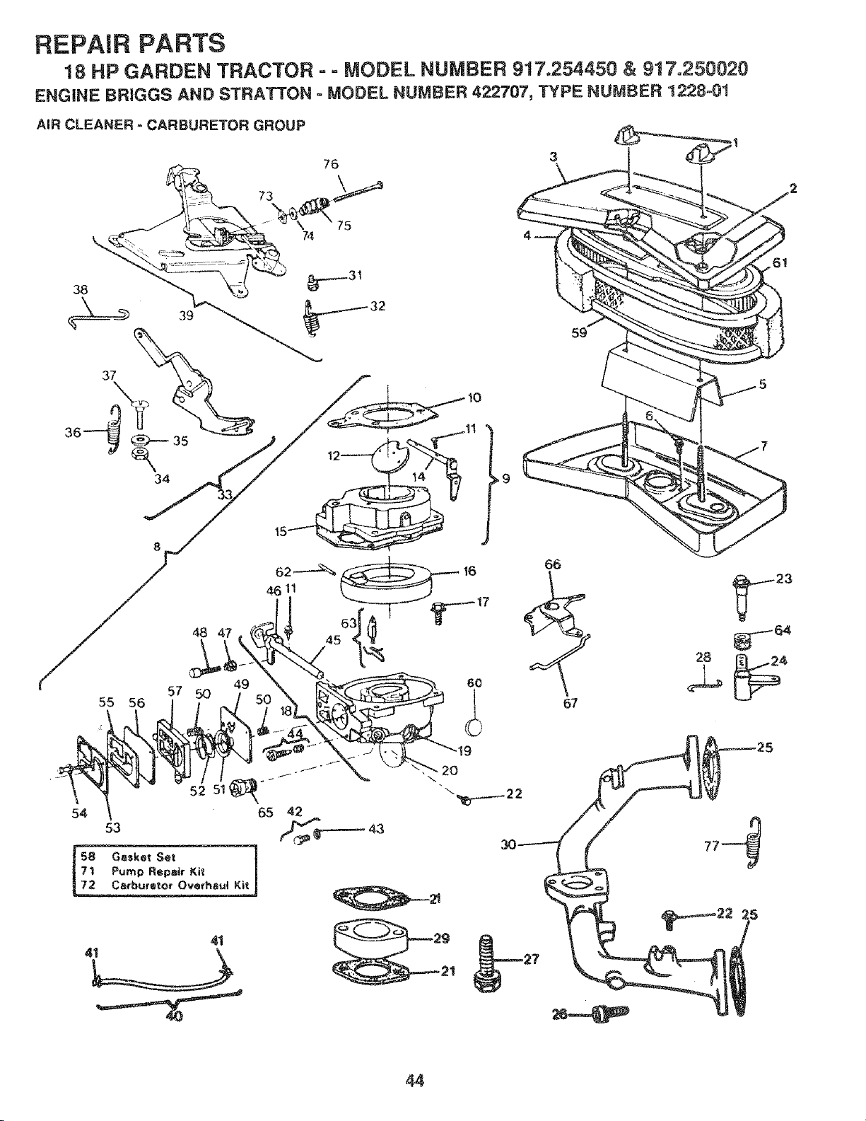
REPAIR PARTS
18 HP GARDEN TRACTOR = = MODEL NUMBER 917.254450 & 917.250020
ENGINE BRIGGS AND STRATTON = MODEL NUMBER 422707, TYPE NUMBER 1228o01
AIR CLEANER - CARBURETOR GROUP
73
76
75
74
38
34
//
57 50 49
55 56
66
67
%
23
54 65
53
44
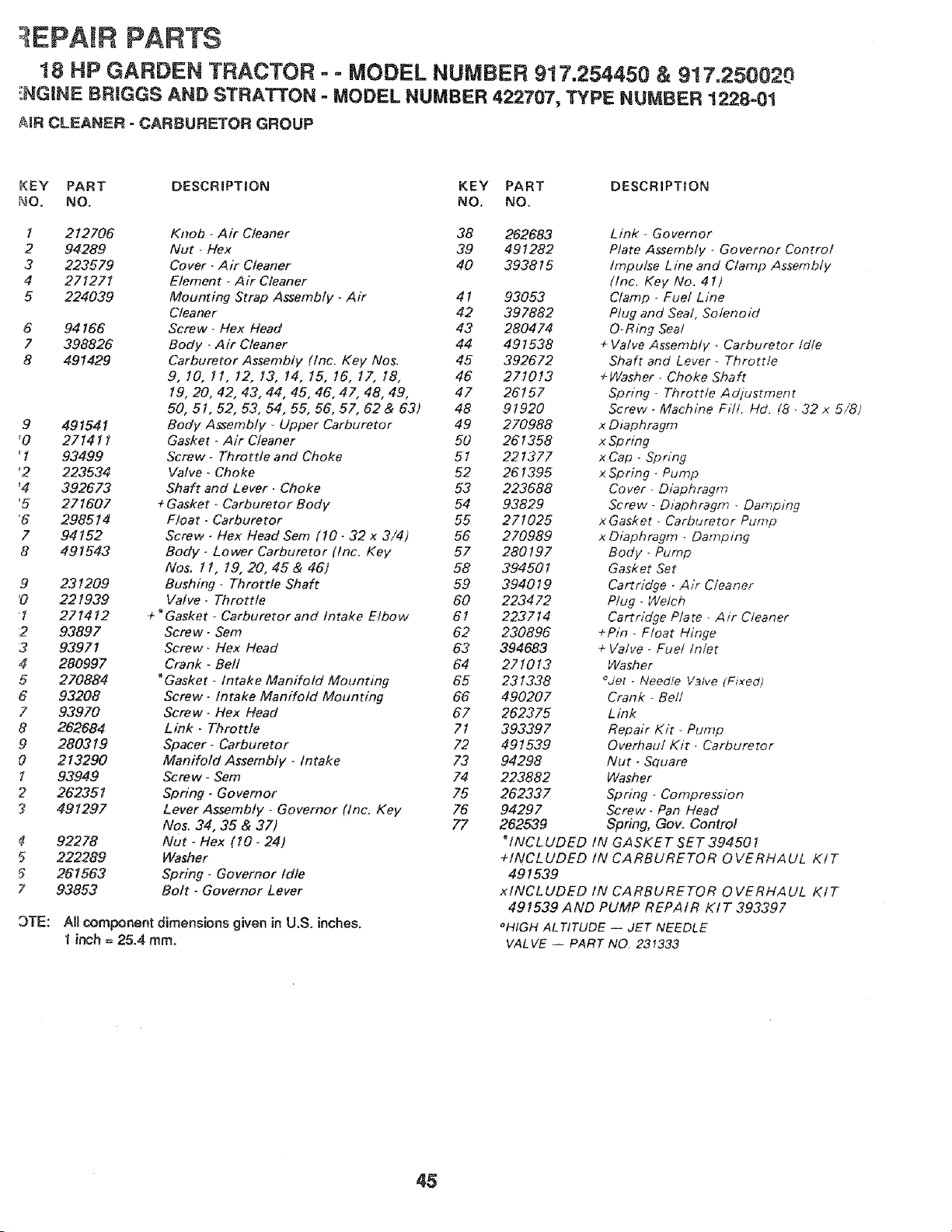
EPAIR PARTS
t 8 HP GARDEN TRACTOR - = MODEL NUMBER 917.254450 & 917.250020
_NGINE BRiGGS AND STRATTON = MODEL NUMBER 422707, TYPE NUMBER 1228-01
#,tR CLEANER - CARBURETOR GROUP
KEY PART DESCRIPTION KEY PART DESCRIPTION
NO, NO. NO. NO.
I 212706
2 94289
3 223579
4 271271
5 224039
6
7
8
94166
398826
491429
9 491541
'0 271411
' 1 93499
'2 223534
'4 392673
'5 271607
'6 298514
7 94152
8 491543
9
'0
!
2
3
4
5
6
7
8
9
O
1
2
7
9TE:
231209
22 t 939
271412
93897
93971
28O997
270884
93208
93970
262684
280319
213290
93949
26235 t
491297
92278
222289
261563
93853
Knob _Air Cleaner 38 262683
Nut -/Vex 39 491282
Cover - Air Cleaner 40 393815
Element _ Air Cleaner
Mounting Strap Assembly- Air 4 t 93053
Cleaner 42 397882
Screw_ Flex Head 43 280474
Body _Air Cleaner 44 491538
Carburetor Assembly (/nc. Key Nos. 45 392672
9. 10. 11. 12. 13. 14. 15. 16. 17. 18. 46 271013
19. 20, 42. 43. 44, 45, 46. 47, 48. 49, 47 28157
50,51.52.53.54,55,56,57,62&63) 48 91920
Body Assembly _ Upper Carburetor 49 270988
Gasket - Air Cleaner 50 261358
Screw- Throttte and Choke 51 221377
Valve - Choke 52 261395
Shaft and Lever. Choke 53 223688
+ Gasket _ Carburetor Body 54 93829
Float - Carburetor 55 271025
Screw- Flex Head Sere (10- 32 x 3/4) 56 270989
Body - Lower Carburetor (tnc, Key 57 280197
No& 11, 19,20,45&46j 58 394501
Bushing - Throttle Shaft 59 394019
Valve- Throttle 60 223472
÷ _Gasket - Carburetor and Intake Elbow 61 223714
Screw- Sem 62 230896
Screw_ Hex Head 63 394683
Crank - Befl 64 271013
_Gasket _ Intake Manifold Mounting 65 231338
Screw- Intake Manifold Mounting 66 490207
Screw- Hex Head 67 262375
Link- Throttle 71 393397
Spacer- Carburetor 72 491539
Manifold Assembly _ In take 73 94298
Screw- Sem 74 223882
Spring- Governor 75 262337
Lever Assembly - Governor (tnc. Key 75 94297
Nos. 34, 35 & 37) 77 262539
Nut. Hex (10- 24)
Washer
Spring- Governor Idle
Bolt _ Governor Lever
All component dimensions given in U.S. inches.
I inch = 25.4 mmo
Link - Governor
Plate Assembly _ Governor Control
impulse Line and Ctamp Assembly
(Inc. Key No. 41)
Clamp . Fuel Line
Plug and Sea!, Solenoid
O-Rmg Seal
+ Valve Assembly - Carburetor Idle
Shaft and Lever- Throttle
÷Washer - Choke Shaft
Spring- Throttle Adjustment
Screw - Machine Fill. Hd. (8 • 32 x 5/8)
x Diaphragm
x Sp ring
x Cap - Sp ring
x Spring - Pump
Cover- Diaphragm
Screw- Diaphragm - Damping
x Gasket _ Carburetor Pump
x Diaphragm - Damping
Body - Pump
Gasket Set
Cartridge. Air Cleaner
Plug- Welch
Ca rtridge Pta te - Air Ctean er
+Pin . Float Hinge
+ Valve - Fuel tn/et
Washer
°Jet -Needie V3[ve (Fixed)
Crank - Bell
Link
Repair Kit _ Pump
Overhaul Kit - Carburetor
Nut - Square
Washer
Spring - Compression
Screw* Pan Head
Spring, Gov, Control
_tNCLUDED IN GASKET SET 394501
+INCLUDED IN CARBURETOR OVERHAUL KIT
491539
x tNCL UDED IN CA RBURE TOR 0 VERHA UL Kt T
491539 AND PUMP REPAIR KIT 393397
_HIGH AL TfTUDE -- JET NEEDLE
VALVE -- PART NO, 231333
45
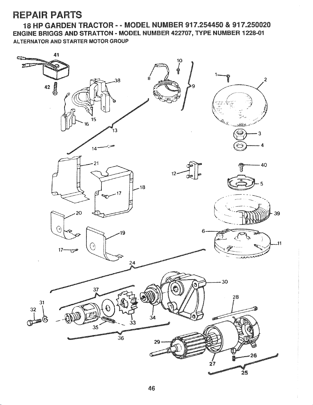
REPAIR PARTS
18 HP GARDEN TRACTOR - ° MODEL NUMBER 917o254450 & 917o250020
ENGINE BRIGGS AND STRATTON - MODEL NUMBER 422707, TYPE NUMBER 1228=01
ALTERNATOR AND STARTER MOTOR GROUP
3t
10
2
_40
5
28
36
46
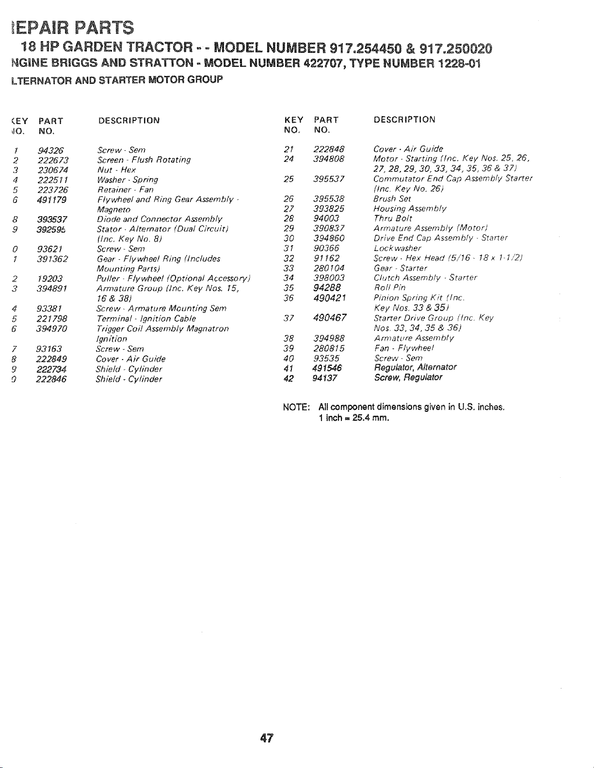
EPAJR PARTS
18 HP GARDEN TRACTOR - - MODEL NUMBER 917.254450 & 917.250020
_GINE BRIGGS AND STRATTON = MODEL NUMBER 422707, TYPE NUMBER 1228-01
LTERNATOR AND STARTER MOTOR GROUP
(EY PART DESCRiPTiON KEY PART DESCRIPTION
dO. NO. NO. NO.
1 94326
2 222673
3 230674
4 222511
5 223726
6 491179
4
5
6
7
8
9
O
393537
392595
93621
391362
19203
394891
93381
221798
394970
93163
222849
222734
222846
Screw- Sere 21 222848
Screen - Flush Rotating 24 394808
Nut - Hex
Washer_ Spring 25 395537
Rerainer- Fan
Flywheel and Ring Gear Assembly - 26 395538
Magneto 27 393825
Diode and Connector Assembly 28 94003
Stator- Alternator (Dual Circuit) 29 390837
(tnc, Key No, 8) 30 394860
Screw- Sere 31 90-366
Gear - Flywheel Ring (Includes 32 91162
Mounting Parts) 33 280104
Puller - Flywheel (Optional Accessory) 34 398003
Armature Group (Inc. Key Nos. 15, 35 94288
16 & 38) 36 490421
Screw. Armature Mounting Sere
Terminal- Ignition Cable 37 490467
Trigger Col! Assembly Magnatron
Ignition 38 394988
Screw- Sem 39 280815
Cover- Air Guide 40 93535
Shield- Cylinder 41 491546
Sbie/d _ Cylinder 42 94137
Cover - Air Guide
Motor. Starting (Inc. Key Nos. 25, 26,
27, 28, 29, 30, 33, 34, 35, 36 & 37)
Commutator End Cap Assembly Starter
(Inc. Key No, 26)
Brush Set
Housing Assembly
Thru Bolt
Armature Assembly (Motor)
Drive End Cap Assembly - Starter
Lock washer
Screw. Hex Head (5/16- !8x 1-1,/2)
Gear _ Starter
Clutch Assembly - Starter
Roll Pin
Pinion Spring Kit (inc.
Key Nos. 33 & 35)
Starter Drive Group (/nc. Key
Nos. 33, 34, 35 & 36)
Armature Assembly,
Fan -Flvwhee/
Screw- Sere
Regulator, Aflemator
Screw, Regulator
NOTE: AI_component dimensions given in U,S. inches.
1 inch = 25.4 rnrn.
47

AHachments That Add to the Usefulness of Your Craftsman Garden Tractor
Sears offers a wide variety of attachments that fit your tractor. Many of these are listed bebw with brief explanations of
how they can help you. This list was current at the time of publication: however, it may change in future years -- more
attachments may be added, changes (including changes in the stock number) may be made in these attachments, or
some may no !onger be available.
Most of these attachments do not require additional hitches or conversion kits (those that do are indicated) and are
designed for easy attaching and detaching. You may order these attachments at most Sears retail stores, catatog sales
offices, and through the catalog.
LAWN SWEEPERS let you collect grass clippings and Jeaves.
Stock No.
71-24030 30-in.
71-24032 32-in.
71-24033 High-Performance 32 in.
71-24038 38-in.
Path
Capacity
9.0 cu. ft.
i0.0 cu. ft.
11.5 cu. ft.
12.5 cu. ft.
LAWN VACS for powerful co{lections of heavy grass clippings and leaves. Alt accept Wand attachment to pick up debris
in hard-to-reach places.
Stock No. Engine Capacity Atso Required
71-2455 3HP 8 bu. 71-26471 chute
71-2452 3HP t2 bu. 7I -26471 chute
71-2447 5HP 25bu. 71-24474 chute
CARTS make hauling easy.
Stock No. Size Capacity
71-24353 4 cu. ft. 400 lb. Dump cart
71-24354 10 cu. ft. t ,000 _b. Hauling cart
71-24355 10 cu. ft° 1,000 lb. Dump cart
71o24356 14 cu. ft. 1,250 lb. Dump cart
71-24357 17 cu. ft. 1,500 Ib. Dump cart
ROLLER for smoother lawn surface. 36-inch wide, 18 inch diameter water-tight drum ho_ds up to 390 lb. of weight.
Rounded edges prevent harm to tuff. Adjustable scraper automatically cleans drum. Stock number 71-24084.
SPREADER/SEEDERS make seeding, t'ertilizing, and weed kilting easy. Broadcast spreaders are also useful for granular
de-icers and sand.
7t-24194
71_24394
Drop type, 36 inch. 12 in. semi.-pneumatic wheeJs. 100 lb. capcity stee! hopper.
Broadcasts over a 5 to 8 foot swath. 70 lb. capacity steel hopper. Noncorrosive spreading spinner,
nylon gear box, stainless steel shaft.
71-24395 Broadcasts 8 to 10 foot swath. 160 lb. capacity.( covers 40,000sq. ft.)No-rust poiypropylene hopper
and impeller. Vinyl hopper cover.
71-2416 Broadcasts 6 to 8 foot swath. 50 lb. capac_y. Corrosion-resistant construction. Polyethylene hopper.
CORING AERATOR takes small ptugs out of soil to allow moisture and nutrients to reach grass roots. 36-inch swath. 24
hardened steel coring tips. 150 lb. capacity weight tray. Stock number 71-24351
AERATOR promotes deep root growth for a healthy lawn. Tapered 2.5" stee! spikes mounted on 10-in. diameter discs
puncture holes in soil at close intercals to let moisture soak it. Steel weight tray for increased penetration. Stock number
71-2435.
DETHATCHER loosens and flips thatch and matted leaves to lawn surface for easy pick up. Twenty spring tine teeth.
Useful to prepare bare areas for reseeding. 40 inch rear mount: Stock number 71-24313. 38 inch front mount: Stock
number 7!-24301.
SPRAYERS use 12-volt DO electric motor that connects to the tractor battery or other 12-volt source, includes booms for
automatic spraying when pulling, and hand hetd wand for spot spraying. Wand has adjustable spray pattern. For applying
herbicides, insecticides, fungicides, and liquid fertilizers.
71-2458 50 psi maximum pressure with 25 foot wand _engthoSprays up to 25 feet with wand.
7!-24398 25 psi maximum pressure with 18 foot wand length. Sprays up to t8 feet with wand.
DOZER BLADE removes snow; grades dirt, sand and gravel. 48 inches wide, I7 inches high, ctears 44 inch path when
angled. Master miftcontrole lever for operator ease. Spdng trip for snow removal on uneven pavement; built - in float for
blade to follow ground contour. Reversible, replaceable scraper bar. (Use with tire chains, wheel weights or rear drawbar
weight). Stock No, 71°244010
48
NOWTHROWER has 40-inch swath. Drum-type auger handles powdery and wet/heavy snow. Mounts easiIy with
mple pin arangement. Discharge chute adjusts to 240 degree arc from tractor seat. 6-inch diameter spout discharges
mow t0 to 50 ft. L#t controlled at tractor seat. (Use with tire chains, wheel weights, or rear drawbar weighb. Stock No.
'1-24077,
iRE CHAINS are heavy du_; closety spaced extraqarge cross links give smooth ride, outstanding traction. Stock No.
1-26945.
tHEEL WEIGHTS provide stability, reduce tearing of tuff when moving on hills, stopping, turning, starting. Provides
_tra weight for traction to pull low-loads, lawn vac. Required for snow removal. For plowing: one in front frame, one in
#ht rear tire, two on left rear tire. For snow blower or dozer blade: one on right rear tire, one on lef_rear tire. 55 pounds.
Lock No. 71-26234. (Front or rear mounting flame bracket Stock No. 71-244360 OR 262235).
HEVRON TIRES for extra traction. Pair of rear tires mounted on wheets. Stock No. 71-24166.
RACTOR CA8 has heavy duty vinyt fabdc over tubular steel frame, fibergJass top; ctear plastic windshield offers 360
_gree visibility. Hinged metal frame doors w_th catch. Keeps operator warm and dry. Remove viny_ and windshield for
_eas sun protector in summer. Stock No. 71-24172
ptional accessories for tractor cab: tinted/tempered solid safety glass wind shied with hand operated wiper (Stock No.
i-26t 68); 12-volt amber caution tight for mounting on cab top (Stock No. 71-26169).
:_ACTOR COVER protects tractor from weather. Made of Evolution 3 fabric (water-repellent, extremeJy breathable, tight
eight, soft, non-abrasive, pliable in all temperatures, durable, stain-tear-puncture resistant, will not shrink or stretch).
lock No. 71-24602_
1LLER has 6hp engine to prepare seed beds, cultivate and compost garden residue. Chain- drive transmission, Six 11
ch din., one piece heat-treated steel tines. Tills 30 inch path, (Requires sleeve hitch Stock No. 71-25231.) Stock No,
1-25249_
'LOW turns soil 6 inches deep, cuts 10 inch furrow. Crank adjustment controls depth, 3-position yoke sets width. Heavy
eel landslk_e for straight forrowing. Stock No, 71-24233.
_lSC HARROW has 2 gangs of 4 steel blades that angle from 10 to 20 degrees 40 inches wide, Can hook 2 units in
ndem. Stock No. 71-24234.
_EAR GRADER/LEVELER BLADE is 424nches wide operated from driver's seat. Reversible steel blade can be angled
30 degrees for grading. Reverses for snow plowing. Stock No. 71-24239.
:LEEVE CULTWATOR is 43 inches wide. Prepares ground for seed ng, helps weed control Steel frame holds 5
Ijustabte sweeps. Adiusts vertically, horizontally Stock No. 71-25304. Optional accessory for cult vator stee forrow
_enerfor wider for wide openings for potatoes, corn, and other deep seeded crops (Stock No. 71-25305).
EIGHT BRACKET for drawbar for snow removal applications. Can be mounted on front of tractor for plowing apptica-
.ns. Uses (1) 55 lb. weight _ number 71o244360.
stensked attachments require sleeve hitch (Stock No. 71-24235) for use with master lift system. Single pin couples/
_coup|es.
49

SERVICE NOTES
50

SUGGESTED GUJOE FOR SiGHTiNG SLOPES FOR SAFE OPERATmON
ONLY RIDE UP AND DOWN HILL,
NOT ACROSS HiLL
SIGHT AND HOLD TH_S LEVEL WITH
SKY LINE OR TREE.
t5 ° MAX.
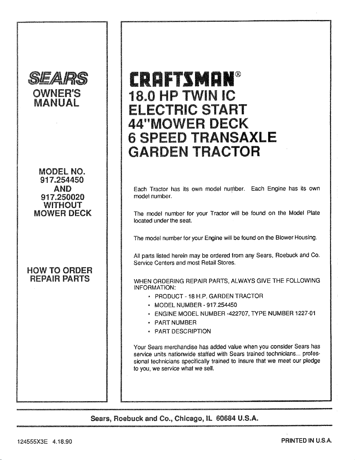
OWNER'S
MANUAL
MODEL NO.
917,254450
AND
917.250020
WITHOUT
MOWER DECK
HOW TO ORDER
REPAIR PARTS
I::1#®
18.0 P TWi lC
ELECTRIC START
44"MOWER DECK
6 SPEE TRANSAXLE
GARDE TRACTO
Each Tractor has its own model number. Each Engine has its own
model number.
The model number for your Tractor will be found on the Model Plate
}ocatod under the seat.
The model number for your Engine will be found on the Blower Housing.
All par_s listed herein may be ordered from any Sears, Roebuck and Co.
Service Centers and most Retail Stores.
WHEN ORDERfNG REPAIR PARTS, ALWAYS GIVE THE FOLLOWING
INFORMATION:
, PRODUCT- 18 H.P. GARDEN TRACTOR
° MODEL NUMBER - 917.254450
, ENGINE MODEL NUMBER -422707, TYPE NUMBER 1227-01
, PART NUMBER
PART DESCRIPTION
Your Sears merchandise has added value when you consider Sears has
service units nationwide staffed with Sears trained technicians,., profes-
sional technicians specifically trained to insure that we meet our pledge
to you, we service what we sell.
Sears, Roebuck and Co., Chicago, IL 60684 U.S.A.
124555X3E 4.t8.90 PRINTEDIN U.S.A.


