Loading ...
Loading ...
Loading ...
d, Holdgovernorcontrol leveragainstidle speed
screw,and adjust idle speedscrewto obtain
1200to 1400RPM(Fig.29).
e. Whilestill holding the governorcontrol lever
against idle speedscrew, turn idle mixture
valve slowly clockwise (_) (lean mixture)
until speed just starts to slow.
f. Turn idle mixture valve back to the midpoint
between rich and lean.
g. Adjust the idle speed screw to obtain 900 to
!200 RPM. Release governor control lever,
h. Move throttle control (on the dashboard) to
"'FAST. "" /f engine hesitates or dies, turn idle
mixture valve approximately 1/8 rum counter-
clockwise (_---) undl engine will accelerate
as throttle control is moved from "SLOW"
to "FAST. ""
4, Fuse Replacement
Replace with 30 amp automotive4ype[duginfuse. Fusescanbe
purchased at al! Sears ServiceCentresand most retail stores.
Fuse is located directlybehind dash,
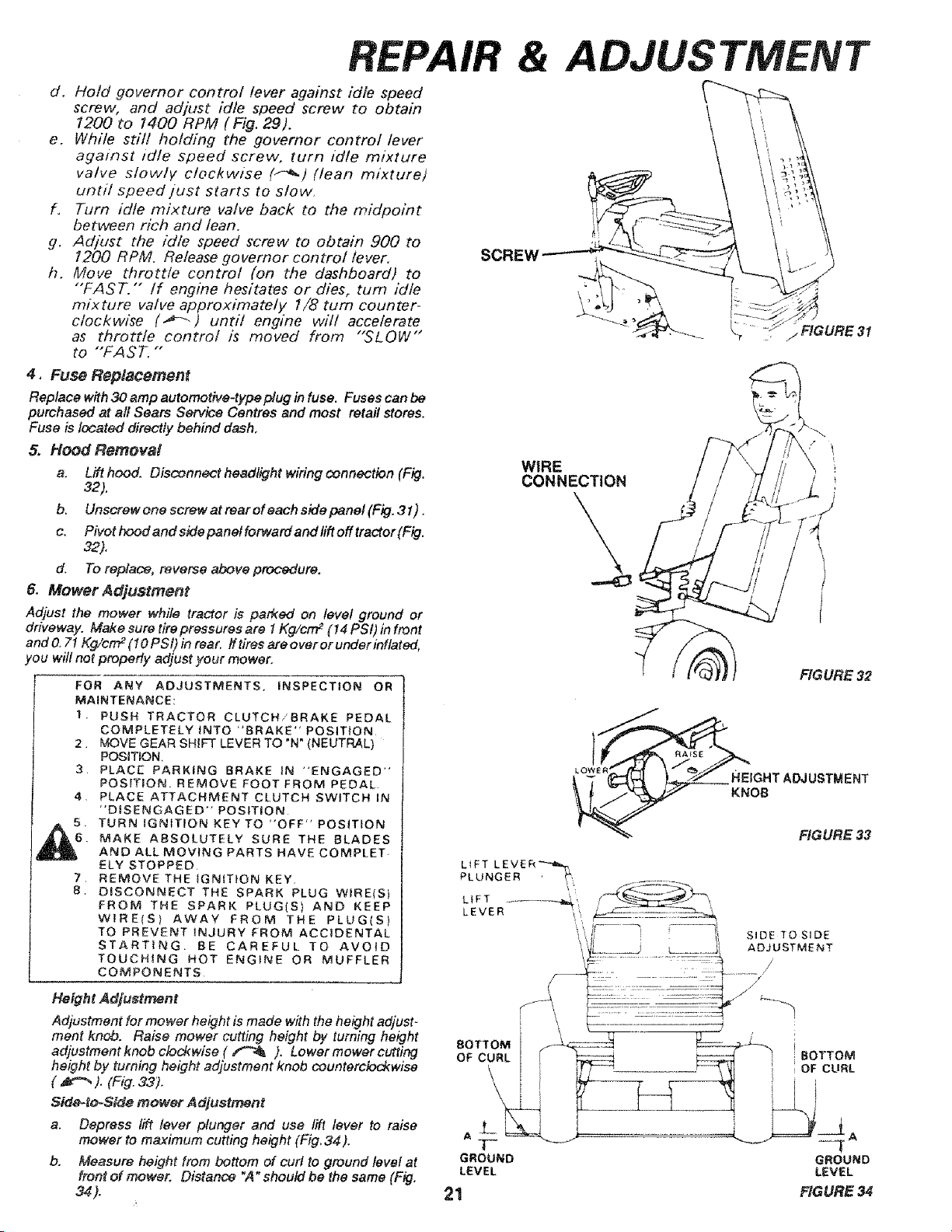
5, Hood Removal
a. Lift hood. Oisconnect headlight wiring connection (Fig,
32).
b, Unscrew one screw at rear of each side panel (Fig. 31) .
c. Pivot hood and side panel forward and lift off tractor (Fig.
32)°
d. To replace, reverse above procedure.
& Mower Adjustment
Adjust the mower while tractor is parked on level ground or
driveway. Make sure tire pressures are 1Kg/crrF (14 PSI) in front
and O.71Kg/cm 2(I0 PSi) in rear, ff tires are over or under inflated,
!ou will not properly adjust your mower.
FOR ANY ADJUSTMENTS, iNSPECTION OR
MAINTENANCE:
1. PUSH TRACTOR CLUTCH/BRAKE PEDAL
COMPLETELY INTO "BRAKE" POSIT{ON
2. MOVE GEAR SHIFT LEVER TO "N" (NEUTRAL)
POSITION,
3. PLACE PARKING BRAKE IN "ENGAGED"
POSITION. REMOVE FOOT FROM PEDAL
4, PLACE ATTACHMENT CLUTCH SWITCH IN
"DISENGAGED" POSITION
5. TURN IGNITION KEY TO "'OFF" POSITION
6. MAKE ABSOLUTELY SURE THE BLADES
AND ALL MOVING PARTS HAVECOMPLET-
ELY STOPPED
7 REMOVE THE IGNITION KEY.
8 DISCONNECT THE SPARK PLUG WIRE<S)
FROM THE SPARK PLUG(S) AND KEEP
WIRE(S) AWAY FROM THE PLUG(S)
TO PREVENT _NJURY FROM ACCIDENTAL
STARTING BE CAREFUL TO AVOID
TOUCHING HOT ENGINE OR MUFFLER
COMPONENTS
Height Adjustment
Adjustment for mower height is made with the height adjust _
ment knob. Raise mower cutting height by turning height
adjustment knob clod{wise ( _ ). Lower mower cutfing
height by turning height adjustment knob counterclockwise
( _ ). (Fig.33).
Sido-to-Side mower Adjustment
a. Depress lift lever plunger and use lift lever to raise
mower to maximum cutting height (Fig, 34).
b. Measure height from bottom of curl to ground level at
front of mower. Distance "A" should be the same (Fig.
34).
WIRE
CONNECTION
FIGURE 32
HEtGHTADJUSTMENT
KNOB
FIGURE 33
L_FT L E V E R _,_._,
PLUNGER _',
LEVER '!',, . ..........
• ,J i SIDE TO SIDE
i 'L_.._ L_ ....... ADJUSTMENT
..........::,:.: ........._y,i
BOTTOM [ _ _ iBOTTOM
OF CURL { iF_ r_ '_I i OF CURL
GROUND GROUND
LEVEL LEVEL
21 FIGURE 34
Loading ...
Loading ...
Loading ...