Loading ...
Loading ...
Loading ...
26
SERVICE AND MAINTENANCE
RELAYS AND SWITCHES
There are several safety switches in the electrical system. If a
function of the safety interlock system described earlier is not
functioning properly, have the electrical system checked by your
authorized service dealer.
PARKING BRAKE ADJUSTMENT
If the tractor does not come to a complete stop when the brake
pedal is completely depressed, or if the tractor’s rear wheels can
roll with the parking brake applied (and the hydrostatic relief
valve open, if equipped), the brake is in need of adjustment. See
your authorized service dealer to have the brake adjusted.
HYDROSTATIC NEUTRAL ADJUSTMENT
If the tractor creeps forward or rearward when neither the
forward nor reverse pedal is depressed, contact your local
authorized dealer to have the neutral setting properly adjusted.
Wheel Alignment
If your tractor pulls to one side or is out of alignment, a wheel
alignment might be necessary. Contact an authorized service
dealer to have the wheels properly aligned.
Deck Removal
WARNING
Use caution to avoid pinching your fingers when rolling the
belt off the PTO pulley.
To remove the cutting deck, proceed as follows:
1. Move the tractor to a level surface, disengage the PTO, stop
the engine, ENGAGE the parking brake.
2. Lower the deck by moving the deck lift lever into the bottom
notch on the right fender.
3. Remove the belt-keeper rod (a), from around the tractor’s
engine pulley, by removing the self-tapping screw (b) that
secures it. See Figure 30.
NOTE: Make a note what hole the other end of the belt-keeper rod
is inserted in for reinstallation purposes.
4. Remove the belt (c) from around the tractor’s engine pulley
and idler pulley(s). See Figure 30.
(c)
(b)
(a)
Figure 30
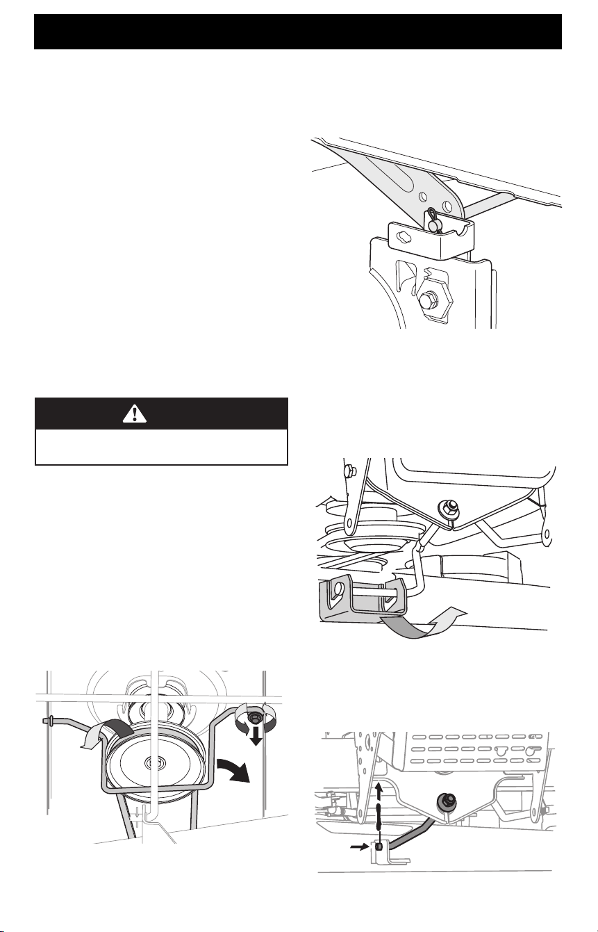
5. Looking at the cutting deck from the left side of the tractor,
locate the bow-tie pin (a) that secures the deck support rod
(b) on the rear left side of the deck. See Figure 31. Remove
the bow-tie pin (a) that secures the deck support rod (b), and
carefully remove the deck support from the deck lift arm.
(a)
(b)
Figure 31
6. Repeat Step 5 on the tractor’s right side.
7. Move the deck lift lever into the top notch on the right fender
to raise the deck lift arms up and out of the way.
8. On 38” decks, gently slide the cutting deck toward the front
of the tractor carefully guiding the hooks on the deck off of
the deck stabilizer rod. See Figure 32.
Figure 32
9. On 36”, 42” and 46” decks, remove the bow-tie pin (a)
securing the deck stabilizer rod (b) to the deck. Slide the deck
lift rod from the mounting weldment on the deck as seen in
Figure 33.
(a)
(a)
(b)
Figure 33
Loading ...
Loading ...
Loading ...