Loading ...
Loading ...
Loading ...
25
SERVICE AND MAINTENANCE
Leveling the Deck (Side-to-Side)
WARNING
Tractor blades are sharp. Wrap the blade or wear gloves, and
use extra caution when servicing them.
1. With the tractor parked on a firm, level surface, place the
deck lift lever in the second notch from the top (second
highest position) and rotate both blades so that they are
perpendicular with the tractor.
2. Measure the distance from the outside of the left blade tip
to the ground and the distance from the outside of the right
blade tip to the ground. Both measurements taken should be
equal. If they’re not, proceed to the next step.
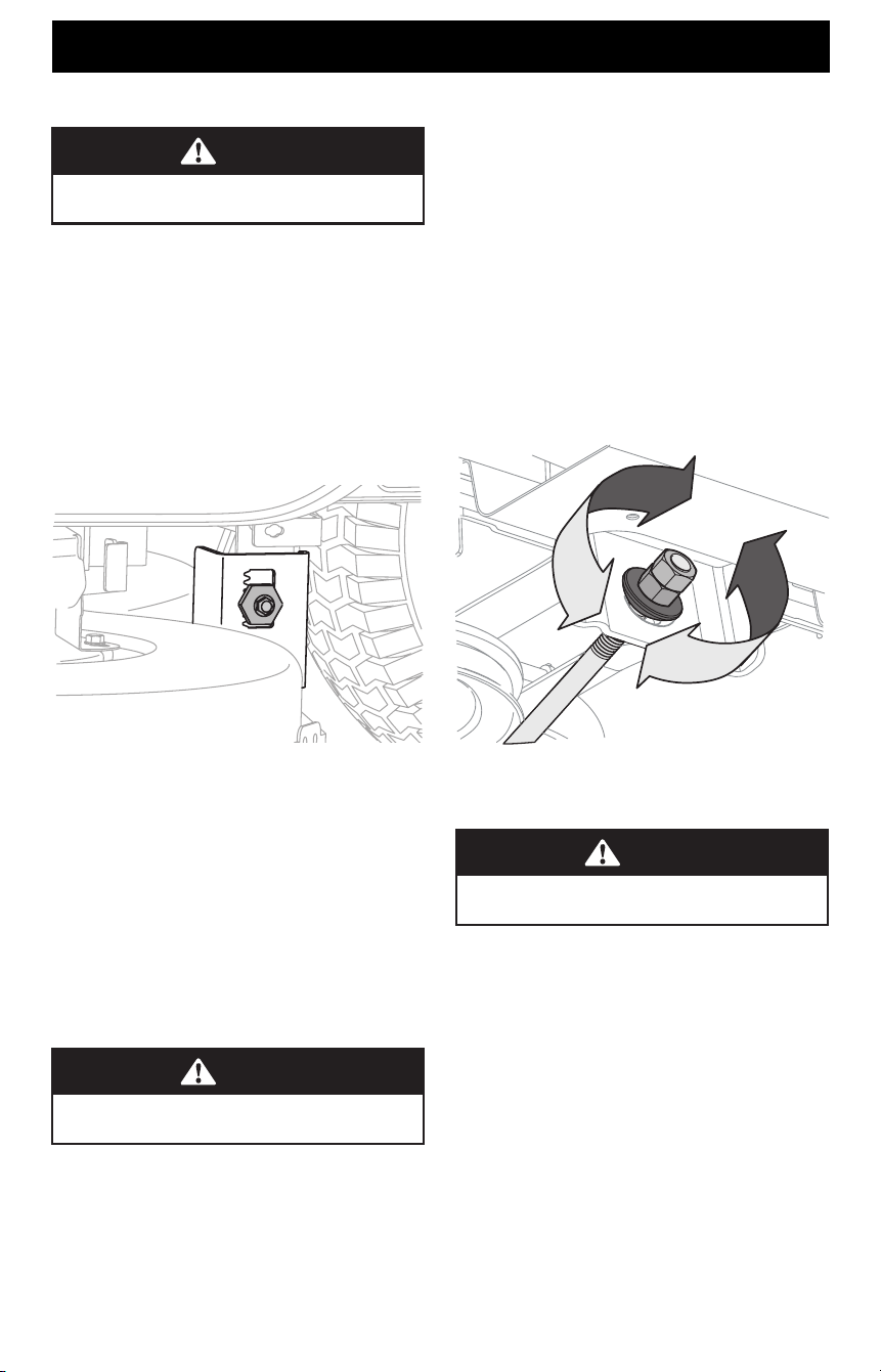
3. Under the rear fenders inside the wheels there is a lift
adjustment hex cap screw and gear for each side of the deck.
See Figure 28.
(a)
Figure 28
4. Loosen, but do NOT remove, the hex cap screw (a) on the left
deck hanger bracket. See Figure 28.
5. Minor adjustments should be made to the adjustment gear
immediately behind the hex cap screw loosened in the
previous step (clockwise/up or counter-clockwise/down).
6. When the proper adjustment is achieved, tighten the hex cap
screw (a) on the left deck hanger bracket. See Figure 28.
7. The deck is properly balanced when both blade tip
measurements taken earlier are equal.
Leveling the Deck (Pitch/Front-to-Rear)
WARNING
Tractor blades are sharp. Wrap the blade or wear gloves, and
use extra caution when servicing them.
The front of the deck is supported by a stabilizer bar that can be
adjusted to level the deck from front to rear. The front of the deck
should be 1⁄4”-3⁄8” (6.35 mm-9.5 mm) lower than the rear of the
deck. Adjust if necessary as follows:
1. Park the tractor on a firm, level surface, place the lever for
lifting the platform on the second to the top notch (second
highest position) and rotate the end of the blade nearest the
discharge chute so that it is parallel with the tractor.
2. Measure the distance from the front of the blade tip to the
ground and the rear of the blade tip to the ground. The front
of the deck should be between 1⁄4”-3⁄8”(6.35 mm-9.5 mm)
less than the rear of deck.
3. Determine the approximate distance necessary for proper
adjustment and proceed, if necessary.
4. To raise the front of the deck, loosen the outer nut then
tighten (thread inward) the inner nut against the front
hanger bracket. See Figure 29. When proper adjustment
is achieved, re-tighten the outer nut to 25-30 ft-lbs (34-
41 N-m).
5. To lower the front of the deck, loosen the outer nut then
loosen (thread outward) the inner nut, away from the front
hanger bracket. See Figure 29. When proper adjustment is
achieved, re-tighten the outer nut.
Figure 29
Adjusting the Deck Wheels
WARNING
Keep hands and feet away from the discharge opening of the
cutting deck.
NOTE: The deck wheels are an anti-scalp feature of the deck and
are not designed to support the weight of the deck.
The deck wheels should be approximately 1⁄4”-1⁄2” (6.35 mm-
12.7 mm) above the ground when the deck is set in the desired
height setting. To adjust the deck wheels see the Assembly
section for instructions.
Service
ELECTRICAL SYSTEM
A fuse is installed to protect the tractor’s electrical system from
damage caused by excessive amperage. Always use the same
capacity fuse for replacement. If the electrical system does not
function, check for a blown fuse.
If you have a recurring problem with blown fuses, have
the tractor’s electrical system checked by your authorized
service dealer.
Loading ...
Loading ...
Loading ...