Be sure power is not connected to the garage door opener
BEFORE installing the safety reversing sensor.
To prevent SERIOUS INJURY or DEATH from a closing garage
door:
• Correctly connect and align the safety reversing sensor. This
required safety device MUST NOT be disabled.
• Install the safety reversing sensor so beam is NO HIGHER
than 6" (15 cm) above garage floor.
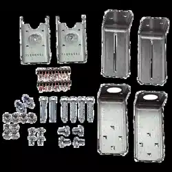
Safety Sensor Brackets
Model 41a6569
Be sure power to the opener is disconnected.
The sending eye transmits an invisible light beam to the receiving
eye. The units can be installed on either side of the garage door as
long as the sun never shines directly into the receiving eye lens.
Look at the label on the connector end of each case to identify the
sensors.
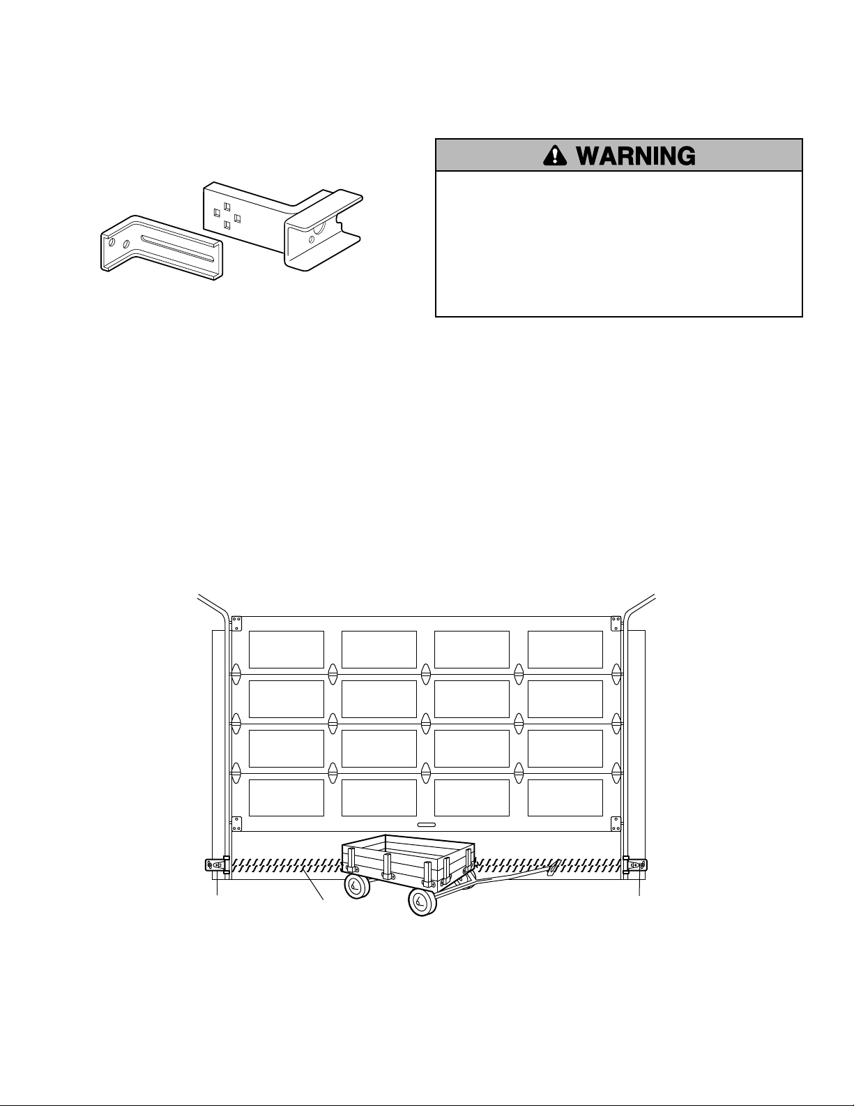
The brackets must be connected and fastened so that the sending
and receiving eyes face each other as shown in Figure 1.
If an obstruction breaks the light beam while the garage door is
closing, the door will stop and reverse to full open position, and
the opener lights will fl ash for 5 seconds.
The brackets must be securely fastened to a solid surface such as
the studs on either side of the door, or add a piece of wood at each
location if installing in masonry construction.
The invisible light beam path must be unobstructed. No part of the
garage door (or door tracks, springs, hinges, rollers or other
hardware) can interrupt the beam while the door is closing. If it
does, use a piece of wood to build out each sensor mounting
location to the minimum depth required for light beam clearance.
Invisible Light Beam
Protection Area
Safety Reversing Sensor
6" (15 cm) max. above floor
Safety Reversing Sensor
6" (15 cm) max. above floor
Figure 1: Facing the door from inside the garage
2
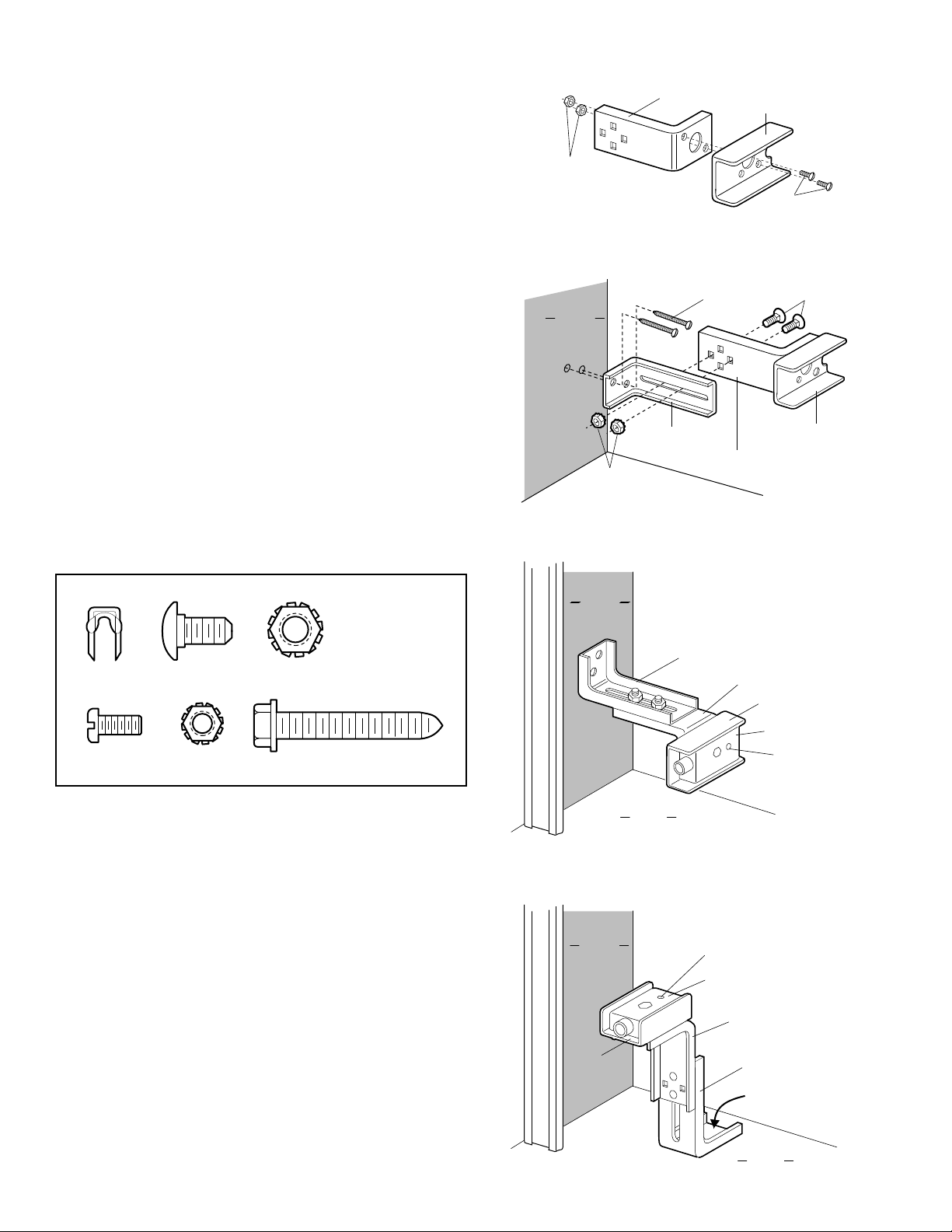
Install the Safety Reversing Sensor
Figures 2 and 3 show assembly of brackets and "C" wrap based on
the recommended installation of the sensors on each side of the
garage door as shown on page 1. Figures 4 and 5 are variations
which may fi t your installation requirements better.
Make sure the wraps and brackets are aligned so the sensors
will face each other across the garage door.
• Fasten the "C" wraps to the mounting brackets having square
holes, using the hardware shown in Figure 2.
• Connect each assembly to a slotted bracket, using the hardware
shown in Figure 3.
NOTE: the alignment of the brackets for left and right sides of
the door.
• Finger tighten the lock nuts.
• Use bracket mounting holes as a template to locate and drill (2)
3/16" diameter pilot holes on both sides of the garage door, 4"- 6"
above the fl oor but not exceeding 6" (15 cm). (See warning on
page 1.)
• Attach bracket assemblies with 1/4"x1-1/2" lag screws as shown
in Figure 3.
• Adjust right and left side bracket assemblies to the same distance
out from the mounting surface. Make sure all door hardware
obstructions are cleared. Tighten the nuts securely.
Garage
Floor
Inside
Garage
Wall
Alternate Floor Mount
Mounting Bracket
with Slot
Mounting Bracket
with Square Holes
"C" Wrap
Sensor
Indicator Light
Attach with
concrete anchors
(not provided)
"C" Wrap
Inside
Garage
Wall
Mounting Bracket
with Square Holes
Mounting Bracket
with Slot
Alternate Wall Mount
Sensor
Garage
Floor
Indicator Light
Mounting Bracket
with Slot
1/4"-20
Lock Nuts
1/4x1-1/2"
Lag Screws
1/4-20x1/2" Carriage Bolts
(with square shoulder)
Inside
Garage
Wall
"C" Wrap
Mounting Bracket
with Square Holes
Mounting Bracket
With Square Holes
#10-32x3/8"
Screws
"C" Wrap
#10-32
Lock Nuts
Figure 2
Figure 3
Figure 4
Figure 5
Lag Screw 1/4x1-1/2"
Screw
#10-32x3/8"
Lock Nut
#10x32
Staples
Carriage Bolts
1/4"-20x1/2"
Lock Nut
1/4"-20
HARDWARE SHOWN ACTUAL SIZE
3
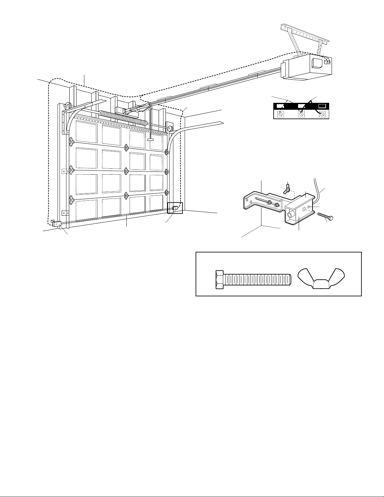
ALIGNING THE SAFETY REVERSING SENSORS
1/4-20x1-1/2"
Hex Bolt
"C" Wrap
Wire
Safety Reversing Sensor
Wing Nut
Invisible Light Beam
Protection Area
Safety Reversing Sensor
Safety Reversing Sensor
Connect Wire to
Opener Terminals
Bell Wire
Bell Wire
Indicator Light
OPENER TERMINAL SCREWS
Sensor
Connections
Wall Control
Connections
(dotted line)
1
2 3
Figure 6
TROUBLESHOOTING THE SAFETY REVERSING SENSORS
1. If the sending eye indicator light does not glow steadily after
installation, check for:
• Electric power to the opener.
• A short in the white or white/black wires. These can occur at
staples, or at opener connections.
• Incorrect wiring between sensors and opener.
• A broken wire.
2. If the sending eye indicator light glows steadily but the
receiving eye indicator light doesn’t:
• Check alignment.
• Check for an open wire to the receiving eye.
3. If the receiving eye indicator light is dim, realign either sensor.
NOTE: When the invisible beam path is obstructed or misaligned
while the door is closing, the door will reverse. If the door is
already open, it will not close. The opener lights will blink 10
times.
• Center each sensor unit in a “C” wrap with lenses pointing
toward each other across the door.
• Secure Safety Reversing Sensors with the hardware shown In
Figure 6. Finger tighten the wing nut on the receiving eye to
allow for fi nal adjustment. Securely tighten the sending eye
wing nut.
• Run wires from both Safety Reversing Sensors to the opener
as shown. Use insulated staples to secure the wire to the wall
and ceiling.
• Connect both sets of wires to the opener terminals as shown
(depending upon your model).
• Plug in the opener. If your opener has the Multi-Function Door
Control, make sure the Lock Feature is off. Indicator lights in
both the sending and receiving eyes will glow steadily if
connections and alignment are correct. If the indicator light is
off the receiving eye (and the invisible light beam path is not
obstructed), alignment is required.
• Loosen the receiving eye wing nut to allow slight rotation of
unit. Adjust Safety Reversing Sensor vertically and horizontally
until the indicator light glows with a steady light.
• When indicator lights are glowing steadily in both units,
tighten the wing nut in the receiving eye unit.
1/4-20x1-1/2"
Hex Bolt
Wing Nut
HARDWARE SHOWN ACTUAL SIZE
-Finished Ceiling-
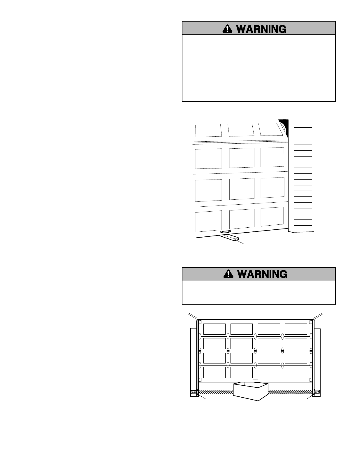
Without a properly installed safety reversal system, persons
(particularly small children) could be SERIOUSLY INJURED or
KILLED by a closing garage door.
• Safety reversal system MUST be tested every month.
• If one control (force or travel limits) is adjusted, the other
control may also need adjustment.
• After ANY adjustments are made, the safety reversal system
MUST be tested. Door MUST reverse on contact with 1-1/2"
high (3.8 cm) object (or 2x4 laid flat) on the floor.
Test the Safety Reversal System
TEST
• With the door fully open, place a 1-1/2" (3.8 cm) board (or a
2x4 laid flat) on the floor, centered under the garage door.
• Operate the door in the down direction. The door must reverse
on striking the obstruction.
ADJUST
• If the door stops on the obstruction, it is not traveling far
enough in the down direction. Increase the DOWN limit by
turning the DOWN limit adjustment screw counterclockwise
1/4 turn.
NOTE: On a sectional door, make sure limit adjustments do not
force the door arm beyond a straight up and down position.
• Repeat the test.
• When the door reverses on the 1-1/2" (3.8 cm) board, remove
the obstruction and run the opener through 3 or 4 complete
travel cycles to test adjustment.
• If the unit continues to fail the Safety Reverse Test, call for a
trained door systems technician.
IMPORTANT SAFETY CHECK:
Test the Safety Reverse System after:
• Each adjustment of door arm length, limits, or force controls.
• Any repair to or adjustment of the garage door (including
springs and hardware).
• Any repair to or buckling of the garage floor.
• Any repair to or adjustment of the opener.
Test The Protector System
®
• Press the remote control push button to open the door.
• Place the opener carton in the path of the door.
• Press the remote control push button to close the door. The
door will not move more than an inch (2.5 cm), and the opener
lights will flash.
The garage door opener will not close from a remote if the
indicator light in either sensor is off (alerting you to the fact that
the sensor is misaligned or obstructed).
If the opener closes the door when the safety reversing sensor
is obstructed (and the sensors are no more than 6" (15 cm)
above the floor), call for a trained door systems technician.
Safety Reversing Sensor
Safety Reversing Sensor
Without a properly installed safety reversing sensor, persons
(particularly small children) could be SERIOUSLY INJURED or
KILLED by a closing garage door.
1-1/2" (3.8 cm) board
(or a 2x4 laid flat)
©
2009, The Chamberlain Group, Inc.
114A3919 All Rights Reserved
