Loading ...
Loading ...
Loading ...
FR
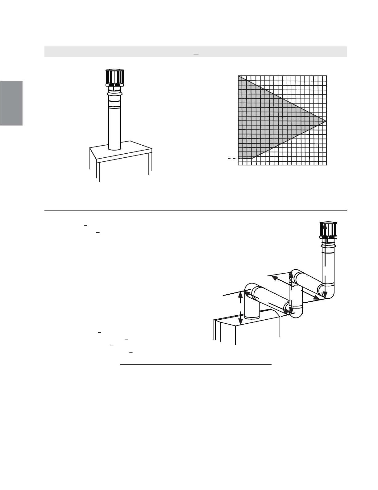
3.9 TERMINAISON VERTICALE
(H
T
) < (V
T
)
Configuration d'évacuation simple.
Consultez le graphique pour déterminer la course verticale
nécessaire V
T
par rapport à la course horizontale requise H
T
.
COURSE
VERTICALE
REQUISE EN
PIEDS
(MÈTRES)V
T
LONGUEUR DES COURSES HORIZONTALES PLUS
LES DÉVIATIONS EN PIEDS (MÈTRES) H
T
Lorsque la configuration de l'évacuation exige plus de zéro coude de 90°, les formules suivantes s'appliquent :
Formule 1 : H
T
< V
T
Formule 2 : H
T
+ V
T
< 40 pieds (12,2m)
Exemple :
V
1
= 5 PI (1,5m)
V
2
= 6 PI (1,8m)
V
3
= 10 PI (3,1m)
V
T
= V
1
+ V
2
+ V
3
= 5PI (1,5m) + 6PI (1,8m) + 10PI (3,1m) = 21 PI (6,4m)
H
1
= 8 PI (2,4m)
H
2
= 2,5 PI (0,8m)
H
R
= H
1
+ H
2
= 8 PI (2,4m) + 2,5 PI (0,8m) = 10,5 PI (3,2m)
H
O
= 0,03 (quatre coudes 90° - 90°)
= 0,03 (360° - 90°) = 8,1 PI (2,5m)
H
T
= H
R
+ H
O
= 10,5PI (3,2m) + 8,1PI (2,5m) = 18,6 PI (5,7m)
H
T
+ V
T
= 18,6PI (5,7m) + 21PI (6,4m) = 39,6 PI (12,1m)
Formule 1 : H
T
< V
T
18,6PI (5,7m) < 21PI (6,4m)
Formule 2 : H
T
+ V
T
< 40 PI (12,2m)
39,6 PI (12,1m) < 40 PI (12,2m)
Puisque les deux formules sont respectées, cette configuration d'évacuation est acceptable.
90°
V
1
V
2
H
1
H
2
La section ombragée à l'intérieur des lignes représente
des valeurs acceptables pour H
T
et V
T
.
90°
90°
90°
V
3
18.1A
0
5
(1,5)
10
(3,1)
15
(4,6)
20
(6,1)
40 (12,2)
10 (3,1)
20 (6,1)
30 (9,1)
3 (0,9)
76
W415-1407 / 11.27.14
Loading ...
Loading ...
Loading ...