Loading ...
Loading ...
Loading ...
W415-1407 / 11.20.14
43
EN
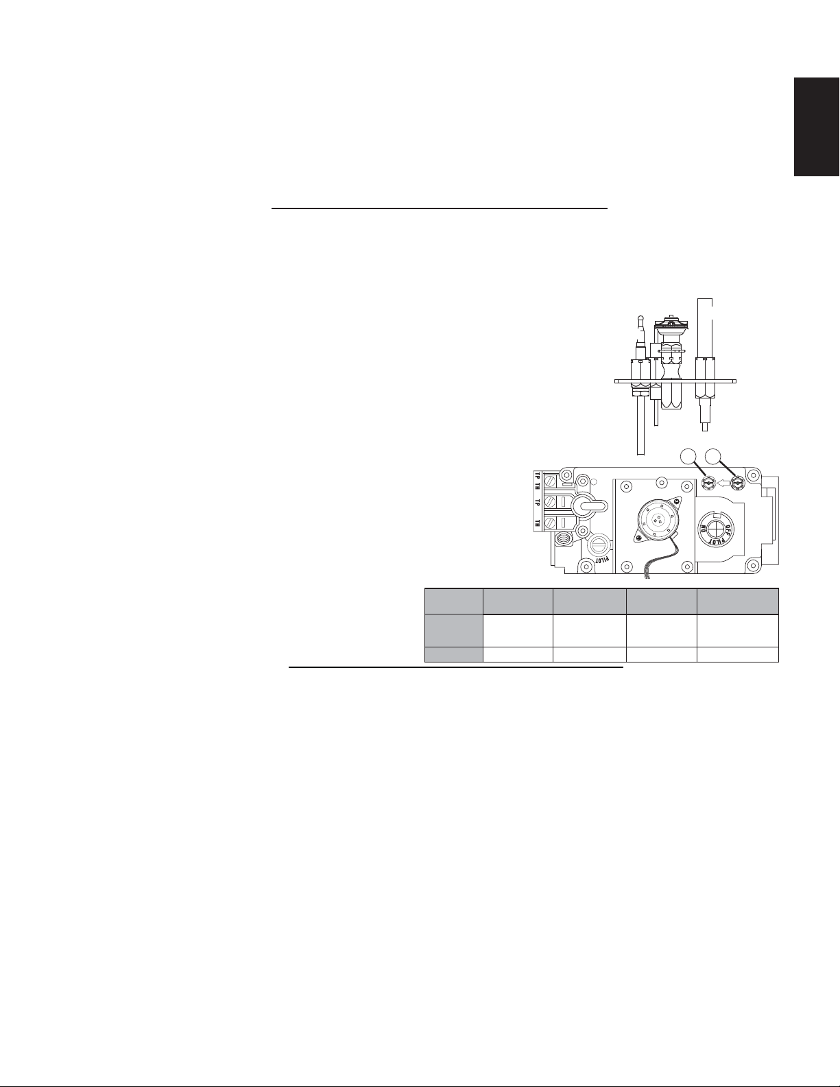
Adjust the pilot screw to provide properly sized fl ame. Turn in a clockwise
direction to reduce the gas fl ow.
Inlet pressure can be checked by turning screw (A) counter-
clockwise until loosened and then placing pressure gauge tubing
over the test point. Gauge should readas described on the chart
below. Check that main burner is operating on “HI”.
Outlet pressure can be checked the same as above using screw
(B). Gauge should readas described on the chart below. Check that
main burner is operating on “HI”.
AFTER TAKING PRESSURE READINGS, TIGHTEN SCREWS
FIRMLY TO SEAL. DO NOT OVER TORQUE. LEAK TEST.
Prior to pilot adjustment, ensure that the pilot assembly has not
been painted. If overspray or painting of the pilot assembly has
occurred remove the paint from the pilot assembly, or replace.
Fine emery cloth or sandpaper can be used to remove the paint
from the pilot hood, electrode and fl ame sensor.
39.2B
A
B
PILOT
BURNER
THERMOCOUPLE
THERMOPILE
Pressure
Inlet
Outlet
Natural Gas
(inches)
Natural Gas
(millibars)
Propane
(inches)
Propane
(millibars)
7"
(MIN. 4.5")
3.5"
13"
(MIN. 11")
10"
17.4mb
(MIN. 11.2mb)
8.7mb
32.4mb
(MIN. 27.4mb)
24.9mb
10.0 ADJUSTMENTS
10.1 RESTRICTING VERTICAL VENTS
10.2 PILOT BURNER ADJUSTMENT
77.3
Vertical installations may display a very active
fl
ame. I
f
this appearance is not desirable, the vent exit must
be restricted using a restrictor vent kit. Refer to “ACCESORIES” in the “REPLACEMENTS” section for the
appropriate kit. This will reduce the velocity of the exhaust gases, slowing down the fl ame pattern and creating
a more traditional gentle fl ame appearance. Specifi c instructions are included with the kit.
Loading ...
Loading ...
Loading ...