Loading ...
Loading ...
Loading ...
1. If the supply cord is damaged, it must be replaced by the manufacturer or its
service agent or a similar quali
ed person. The type of connecting wire is
H05RN-F
or H07RN-F.
2. If the fuse on PC board is broken please change it with the
type of
T. 3.15A/250V.
3. The wiring method should be in line with the local wiring standard.
4. After installation, the power plug should be easily reached.
5. A breaker should be incorporated into
xed wiring. The breaker should be
all-pole
switch and the distance between its two contacts should be not less
than 3mm.
3
Outdoor unit
Indoor unit
A
B
Outdoor unit
Indoor unit
A
B
A
B
Outdoor unit
Indoor unit
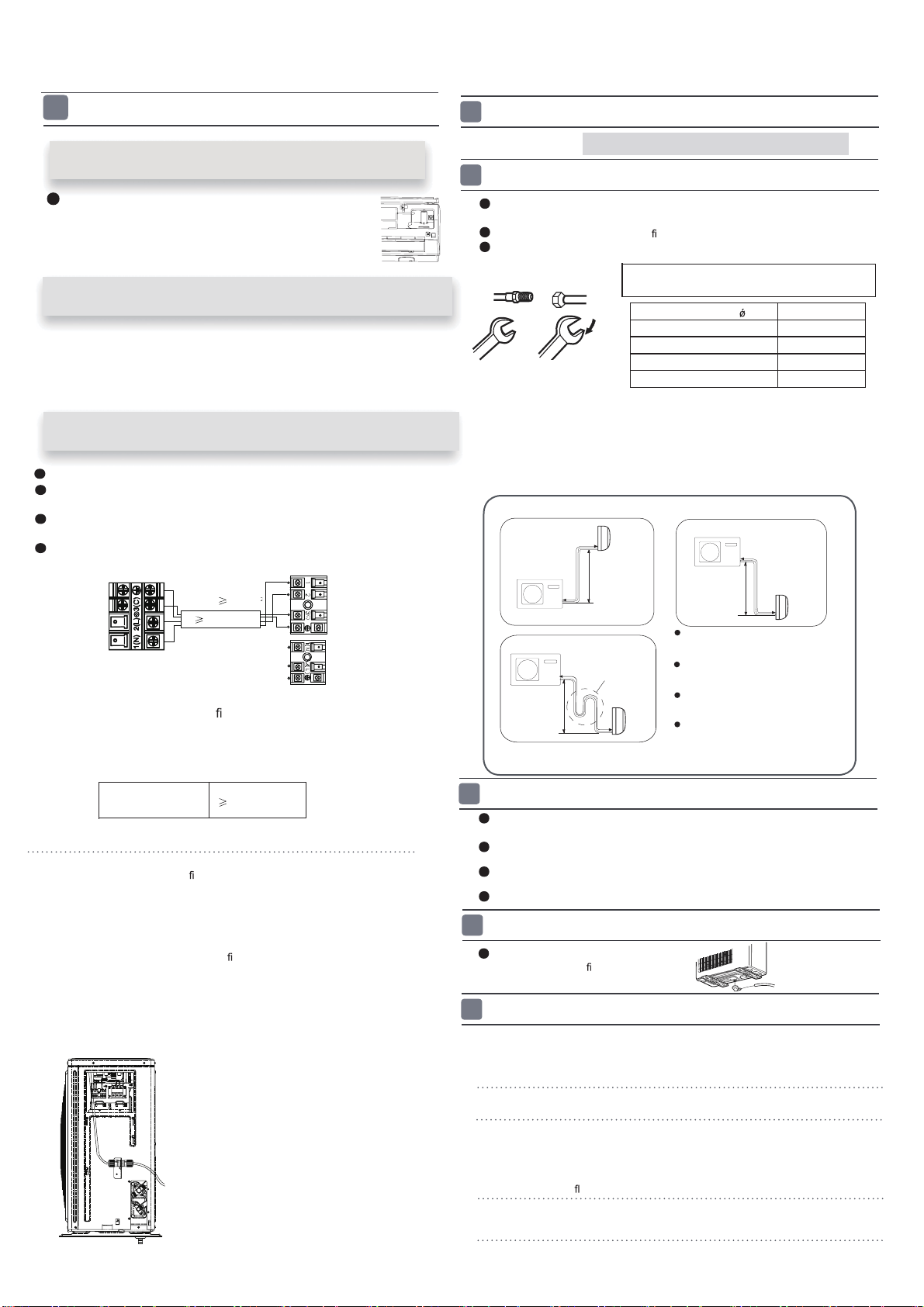
Oil trap
Outdoor unit
Install according to Drawing for the installation of indoor and
outdoor units
To bend a pipe, give the roundness as large as possible not to crush the pipe ,
and the bending radius should be 30 to 40
mm or longer.
Connecting the pipe of gas side
rst makes working easier.
The connection pipe is specialized for R410A.
Use the same method on indoor unit. Loosen the screws on
terminal block and
insert the plugs fully into terminal block, then tighten the screws.
Insert the cable according to terminal number in the same manner as the indoor
unit.
If wiring is not correct, proper operation can not be carried out and controller
may be damaged.
Fix the cable with a clamp.
Installation of Outdoor Unit
Half union
Flare nut
Torque wrench
CAUTION
Be careful that matters, such as wastes of sands, etc. shall not enter the pipe.
The standard pipe length is 5m. If it is over 7m, the function of the unit will be
affected. If the pipe has to be lengthened, the refrigerant should be charged,
according to 20 g/m. But the charge of refrigerant must
be conducted by profes-
sional air conditioner engineer. Before adding additional refrigerant, perform air
purging from the refrigerant pipes and indoor unit using a vacuum pump,then
Spanner
Forced fastening without careful centering may
damage the threads and cause a leakage of gas.
Pipe Diameter( ) Fastening torque
Liquid side6.35mm(1/4") 18N.m
Liquid/Gas side9.52mm(3/8") 42 N.m
Gas side 12.7mm(1/2") 55N.m
Gas side 15.88mm(5/8") 60 N.m
1
Connection of pipes
2
charge additional refrigerant.
Connection
3
If the drain-elbow is used,
please attach it as gure. (Note:
Only for heat pump unit.)
Detach the service port’s cap of
1.
3-way valve, the valve rod’s cap for 2-way valve
and 3-way’s, connect the service port into the
projection of charge hose (Iow)
for gaugemanifold.
Then connect the projection of charge hose (center) for gau-
gemanifold into vacuum pump.
Open the handle at Iow in
2.
gaugemanifold, operate vacuum pump. If the scale-
moves of gause (Iow) reach vacuum condition in a moment, check
1. again.
Vacuumi
ze for over 15min.And check the level gauge which should read -0.1MPa
3.
(76 cm Hg) at Iow
pressure side. After the
completion of vacuumizing, close the
handle ‘Lo’ in gaugemanifold and stop the operation of the vacuum pump. Check
condition of the scale and hold it for 1-2min. If the scale-moves back in spite of
tightening, make
aring work again, the return to the beginning of 3 .
Attaching Drain-Elbow
4
Purging Method:To use vacuum pump
5
Open the valve rod for the 2-way valve to an angle of4.
anticlockwise 90 degrees.
After 6 seconds, close the
2-way valve and make the
inspection of gas leakage.
4
Connecting the indoor/outdoor Electric Cable
Max.Elevation:
In case the elevation A is more
than 5m, oil trap shoud be
installed every 5~7m
Max. Length:
In case the pipe length B is
more than 7m, the refrigerant
should be charged, according
to 20 g/m for 05-13K and 50g/m for
05-13K:Amax=10m
18-24K:Amax=15m
05-13K:Bmax=15m
18-24K:Bmax=25m
18-24K.
R
emove terminal cover at rig
ht bottom corner of
indoor unit, then take
off wiring cover by removing
its screws.
Removing the wiring cover
1. Insert from outside the room cable into left side of the wall
hole, in which the pipe has already existed.
2. Pull out the cable on the front side, and connect the cable
making a loop.
When connecting the cable, con
rm the terminal number of indoor and
o
be carried out and will cause defect.
utdoor units carefully. If wiring is not correct, proper operation can not
Insert the cable from the back
side of the unit, then pull it out
on the front side.
Loosen the screws and insert
the cable ends fully into
terminal block, then
tighten the screws.
Pull the cable slightly to
make sure the cables have
been properly inserted and
tightened.
After the cable connection,
never fail to fasten the connected cable with the
wiring cover.
When connecting the cable after installing the indoor unit
When connecting the cable before installing the indoor unit
Note:
Connecting wiring
4G1.0mm
2
{
POWER
-mod 09-24: 3G2.5mm
Indoor unit
Outdoor unit
4G1.5mm
2
Power cable:
6.Please consult your reseller and/or installer to determine if you have a DRED
appliance.
Connect output from your home's electricity power meter (where
(This function is unavailable on some models.)
available) to the RJ45 connector on the outdoor unit, as shown.
Loading ...