SERVICE MANAUL
Wall Mounted Type
DC Inverter
1U71SABFRA
Model No.
This service information is designed for experienced repair technicians only and is not designed for use by the general public.
It does not contain warnings or cautions to advise non-technical individuals of potential dangers in attempting to service a product.
Products powered by electricity should be serviced or repaired only by experienced professional technicians. Any attempt to service or
Repair the product or products dealt with in this service information by anyone else could result in serious injury or death
WARNING
(Qingdao Haier Air Conditioner General corp. , Ltd)
All rights reserved. Unauthorized copying and distribution is a violation of law
Haier Group
Version V1 Date 2018-06-29
Contents
Domestic air conditioner
Contents
1. Introduction ............................................................................................1
2. Specifications.........................................................................................7
3. Sensors list ............................................................................................8
4. Piping diagrams .....................................................................................9
5. Operation range....................................................................................10
6. PCB Diagram .......................................................................................11
7. Functions and Control............................................................................
8. Dimensional drawings...........................................................................
9. Conter of gravity ...................................................................................
10. Service Diagnosis ...............................................................................
11. Performance and cerves diagrams.....................................................
12. Circuit diagrams..................................................................................
15
45
31
30
30
53
Introduction
Domestic air conditioner
1 Introduction
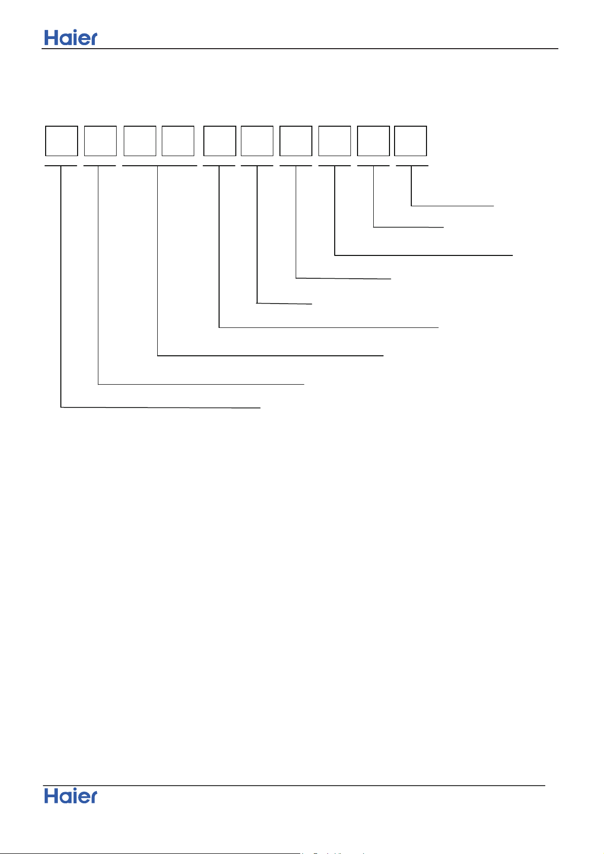
1.1 Model name explanation
1
1 U 7 S A B F AR
The maximum combination number
Type of outdoor unit : U (normal type)
Nominal cooling capacity (7100W)
Platform of outdoor units: S (S platform)
Australia
Version number
Heat pump & R32 refrigerant
DC inverter
Apply toT1; 220~240V50Hz/1P h
1
Introduction
Domestic air conditioner
1.2 Safety Cautions
Be sure to read the following safety cautions before conducting repair work.
The caution items are classified into “Warning” and “Caution”. The “Warning” items are especially important
since they can lead to death or serious injury if they are not followed closely. The “Caution” items can also
lead
to serious accidents under some conditions if they are not followed. Therefore, be sure to observe all the
safety
caution items described below.
About the pictograms
ƸThis symbol indicates an item for which caution must be exercised.
The pictogram shows the item to which attention must be paid.
○ This symbol indicates a prohibited action.
The prohibited item or action is shown inside or near the symbol.
● This symbol indicates an action that must be taken, or an instruction.
The instruction is shown inside or near the symbol.
After the repair work is complete, be sure to conduct a test operation to ensure that the equipment operates
Normally, and explain the cautions for operating the product to the customer.
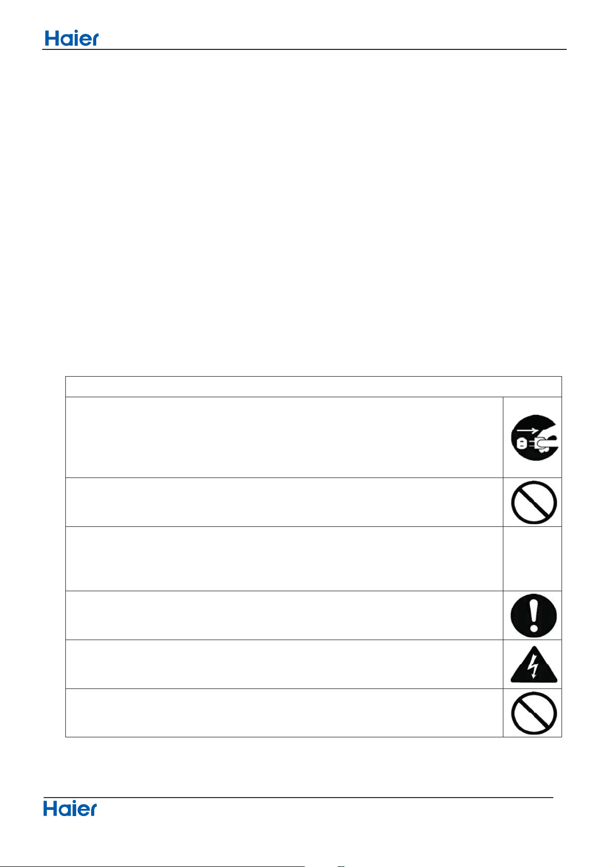
1.2.1 Caution in Repair
Warning
Be sure to disconnect the power cable plug from the plug socket before disassembling the equipment for
a repair.
Working on the equipment that is connected to a power supply can cause an electrical shook.
If it is necessary to supply power to the equipment to conduct the repair or inspecting the circuits, do not
touch any electrically charged sections of the equipment.
If the refrigerant gas discharges during the repair work, do not touch the discharging refrigerant gas .The
refrigerant gas can cause frostbite.
When disconnecting the suction or discharge pipe of the compressor at the welded section, release the
refrigerant gas completely at a well-ventilated place first.
If there is a gas remaining inside the compressor , the refrigerant gas or cooling machine oil discharges
when the pipe is disconnected, and it can cause injury.
If the refrigerant gas leaks during the repair work, ventilate the area. The refrigerant gas can generate
toxic gases when it contacts flames.
The step-up capacitor supplies high-voltage electricity to the electrical components of the outdoor unit.
Be sure to discharge the capacitor completely before conducting repair work . A charged capacitor can
cause an electrical shock.
Do not start or stop the air conditioner operation by plugging or unplugging the power cable plug.
Plugging or unplugging the power cable plug to operate the equipment can cause an electrical shock or
fire.
2
Introduction
Domestic air conditioner
Warning
Do not repair the electrical components with wet hands . Working on the equipment with wet hands can
cause an electrical shock
Do not clean the air conditioner by splashing water. Washing the unit with water can cause an electrical
shock.
Be sure to provide the grounding when repairing the equipment in a humid or wet place, to avoid
electrical
shock.
Be sure to turn off the power switch and unplug the power cable when cleaning the equipment. The
internal fan rotates at a high speed, and cause injury.
Do not tilt the unit when removing it. The water inside the unit can spill and wet the furniture and floor.
Be sure to check that the cooling cycle section has cooled down sufficiently before conducting repair
work. Working on the unit when the cooling cycle section is hot can cause burns.
Use the welder in a well-ventilated place. Using the welder in an enclosed room can cause oxygen
deficiency.
1.2.2 Cautions Regarding Products after Repair
Warning
Be sure to use parts listed in the service parts list of the applicable model and appropriate tools to
conduct repair work. Never attempt to modify the equipment. The use of inappropriate parts or tools can
cause an electrical shock, excessive heat generation or fire.
When relocating the equipment, make sure that the new installation site has sufficient strength to
withstand the weight of the equipment.
If the installation site does not have sufficient strength and if the installation work is not conducted
securely, the equipment can fall and cause injury.
Be sure to install the product correctly by using the provided standard installation frame.
Incorrect use of the installation frame and improper installation can cause the equipment to fall, resulting
in injury.
For
integral
units only
Be sure to install the product securely in the installation frame mounted on a window frame.
If the unit is not securely mounted, it can fall and cause injury.
For
integral
units only
3
Introduction
Domestic air conditioner
Warning
Be sure to use an exclusive power circuit for the equipment, and follow the technical standards related to
the electrical equipment, the internal wiring regulations and the instruction manual for installation when
conducting electrical work.
Insufficient power circuit capacity and improper electrical work can cause an electrical shock or fire.
Be sure to use the specified cable to connect between the indoor and outdoor units. Make the
connections securely and route the cable properly so that there is no force pulling the cable at the
connection terminals.
Improper connections can cause excessive heat generation or fire.
When connecting the cable between the indoor and outdoor units, make sure that the terminal cover
does
not lift off or dismount because of the cable.
If the cover is not mounted properly, the terminal connection section can cause an electrical shock,
excessive heat generation or fire.
Do not damage or modify the power cable.
Damaged or modified power cable can cause an electrical shock or fire. Placing heavy items on the
power cable, and heating or pulling the power cable can damage the cable.
Do not mix air or gas other than the specified refrigerant (R-410A / R22) in the refrigerant system.
If air enters the cooling system, an excessively high pressure results, causing equipment damage
and injury.
If the refrigerant gas leaks, be sure to locate the leak and repair it before charging the refrigerant. After
charging refrigerant, make sure that there is no refrigerant leak.
If the leak cannot be located and the repair work must be stopped, be sure to perform pump-down and
close the service valve, to prevent the refrigerant gas from leaking into the room. The refrigerant gas
itself
is harmless, but it can generate toxic gases when it contacts flames, such as fan and other heaters,
stoves and ranges.
.
When replacing the coin battery in the remote controller, be sure to disposed of the old battery to prevent
children from swallowing it.
If a child swallows the coin battery, see a doctor immediately.
Caution
Installation of a leakage breaker is necessary in some cases depending on the conditions of the
installation site, to prevent electrical shocks.
4
Introduction
Domestic air conditioner
Do not install the equipment in a place where there is a possibility of combustible gas leaks.
If a combustible gas leaks and remains around the unit, it can cause a fire.
Be sure to install the packing and seal on the installation frame properly. If the packing and seal are not
installed properly, water can enter the room and wet the furniture and floor.
1.2.3 Inspection after Repair
Warning
Check to make sure that the power cable plug is not dirty or loose, then insert the plug into a power outlet
all the way.
If the plug has dust or loose connection, it can cause an electrical shock or fire.
If the power cable and lead wires have scratches or deteriorated, be sure to replace them.
Damaged cable and wires can cause an electrical shock, excessive heat generation or fire.
Warning
Do not use a joined power cable or extension cable, or share the same power outlet with other electrical
appliances since it can cause an electrical shock, excessive heat generation or fire.
Caution
Check to see if the parts and wires are mounted and connected properly, and if the connections at the
soldered or crimped terminals are secure. Improper installation and connections can cause excessive
heat generation, fire or an electrical shock.
If the installation platform or frame has corroded, replace it. Corroded installation platform or frame can
cause the unit to fall, resulting in injury.
5
Introduction
Domestic air conditioner
Check the grounding, and repair it if the equipment is not properly grounded. Improper grounding can
cause an electrical shock.
Be sure to measure the insulation resistance after the repair, and make sure that the resistance is 1 M
ohm or higher.
Faulty insulation can cause an electrical shock.
Be sure to check the drainage of the indoor unit after the repair.
Faulty drainage can cause the water to enter the room and wet the furniture and floor.
1.2.4 Using Icons
Icons are used to attract the attention of the reader to specific information. The meaning of each icon is described in
the table below:
1.2.5 Using Icons List
Icon Type of Information Description
Note
Note
A “note” provides information that is not indispensable, but may
nevertheless be valuable to the reader, such as tips and tricks.
Caution
Caution
A “caution” is used when there is danger that the reader, through
incorrect manipulation, may damage equipment, loose data, get
an
unexpected result or has to restart (part of) a procedure.
Warning
Warning
A “warning” is used when there is danger of personal injury.
Reference
A “reference” guides the reader to other places in this binder or in
this manual, where he/she will find additional information on a
specific topic.
6
Specification
Domestic air conditioner
2. Specifications
- 1U53RABFRA
NOMINAL DISTRIBUTION SYSTEM VOLTAGE
1/esahP
05zHycneuqerF
220~240VegatloV
TECHNICAL SPECIFICATIONS-UNIT
Dimensions H*W*D mm
Packaged
Dimensions
H*W*D m
54GK/thgieW
60GK/thgiewssorG
Sound level
69
BderusserpdnuoS
B(A)drewopdnuoS
ELECTRICAL SPECIFICATIONS
gnitaehgnilooc
8.247.51AtnerrucgninnurlanimoN
Maximum running current A 11.4 12.6
TECHNICAL SPECIFICATIONS-PARTS
gnitaehgnilooc
Compressor
rosserpmoCyratoRepyT
ledoM
1800WtuptuorotoM
Oil type
0.5LemulovegrahcliO
Fan
naflaixAepyT
93/93WtuptuorotoM
3400h/³m)hgih(etarwolfriA
mpr)wol/hgih(deepS
Heat
exchanger
Type
ML fin-
7HI-HX tube
4.1*34*2.5hctif*egats*woR
7
GTD186UKQA8JT6
A C S - 6 8 R
850/300
58
NOMINAL CAPACITY and NOMINAL INPUT
gnitaehgnilooc
Capacity rated
W
Btu/h
18901710W)detaR(noitpmusnoCrewoP
4.024.15W/WPOC/REE
h/³m
lavomeRerutsioM
2.4*10 ³
7100(1900-8400)
24200(6500-28600)
7600(2000-10200)
920×385×762
1085×487×843
25900(6800-34800)
Specification
Domestic air conditioner
Note: the data are based on the conditions shown in the table below
htgnelgnipiPgnitaehgnilooc
Indoor: 27 DB/19 WB
Outdoor: 35 DB/24 WB
Indoor:20 DB
Outdoor: 7 DB/6 WB
5m
3 Sensors list
type Description Qty
3 in 1
itcetedrofdesustIrosnestneibmA edisroodtuofoerutarepmetgn
Suction sensor
Its used for detecting suction pipe temperature of compressor to
adjust gas flowing
1
Defrostin
g
sensor
Its used for controlling outdoor defrosting at heating mode
taeh-revofoesacnirosser
p
mocrofdesustI
rosnes
Discharging
Conversation formulae
Kcal/h= KW×860
Btu/h= KW×3414
cfm=m³/min×35.3
8
TECHNICAL SPECIFICATIONS-OTHERS
Refrigerant
circuit
Refrigerant type
R32
Refrigerant charge KG
1.45
Refrigerant control
EXV
Piping connections
(external diameter)
liquid mm
gas mm
drain mm
Heat insulation type Both liquid and Gas pipes
Max. piping Length m 25
Max. Level Difference m
Chargeless m 10
Amount of Additional Charge of Refrigerant g/m 20
International Protection degree
IP 24
12.7
17
circuit
15
Pinping diagrams
Domestic air conditioner
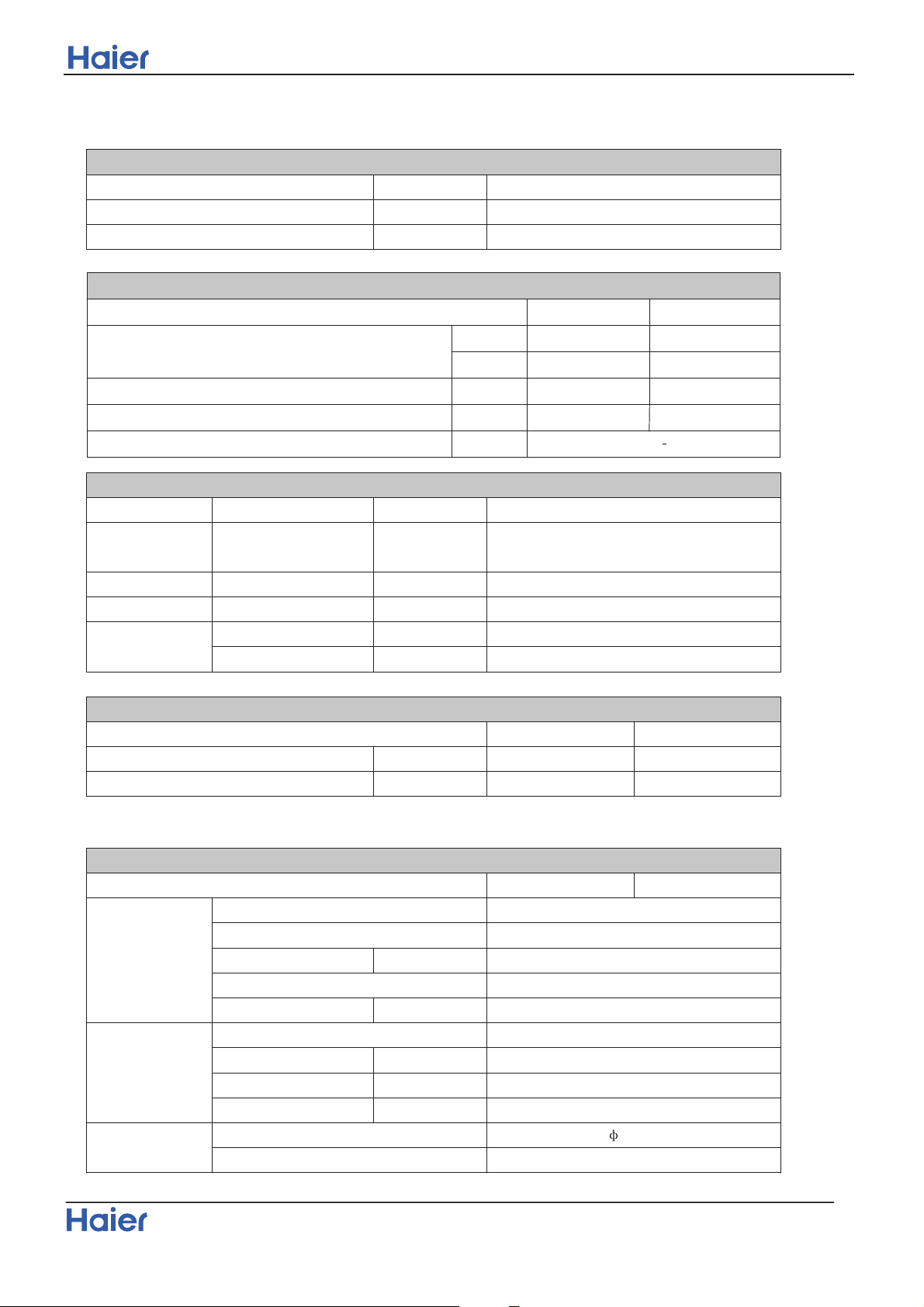
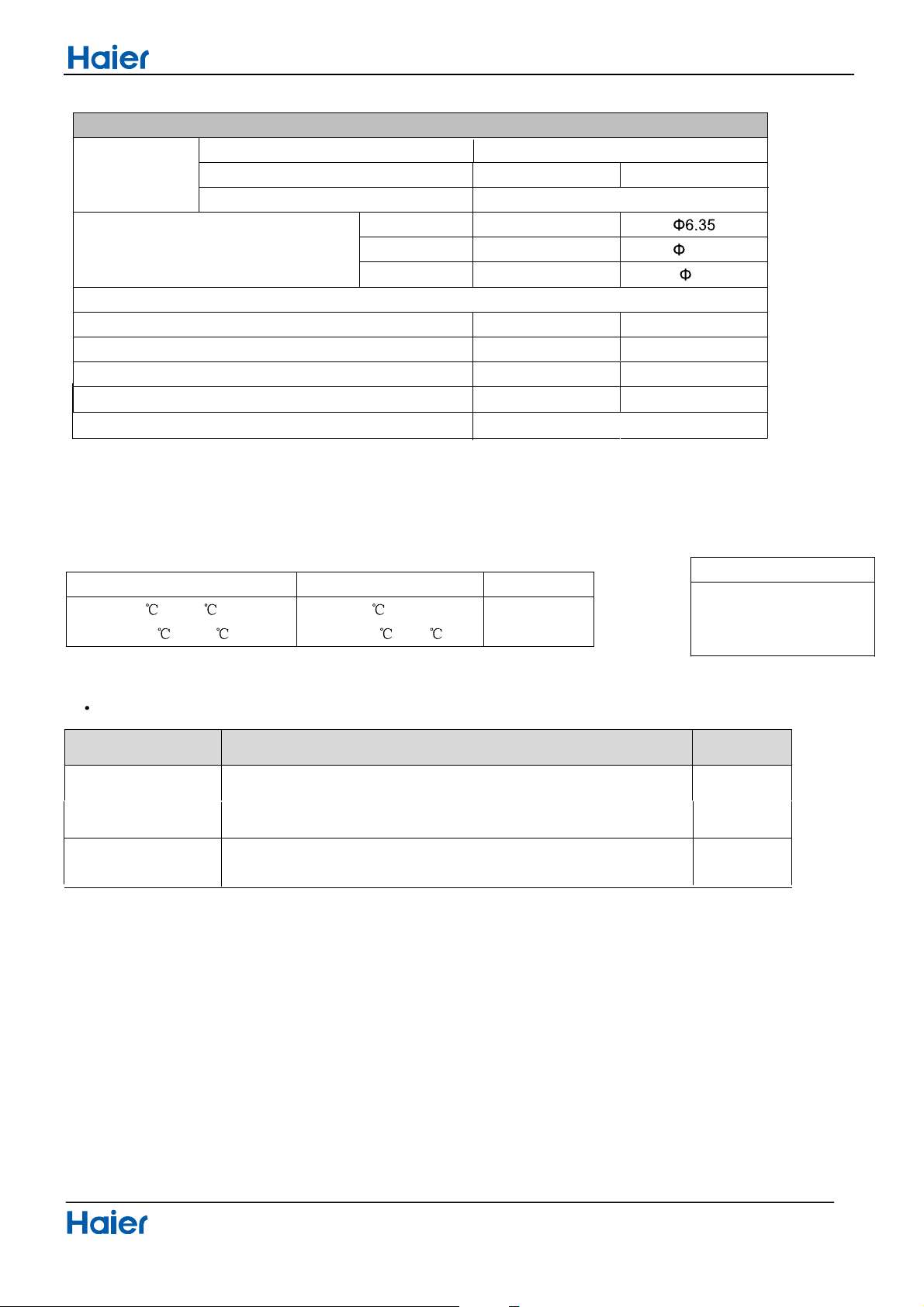
4.Pinping diagrams
Filter
Filter
Operation range
Domestic air conditioner
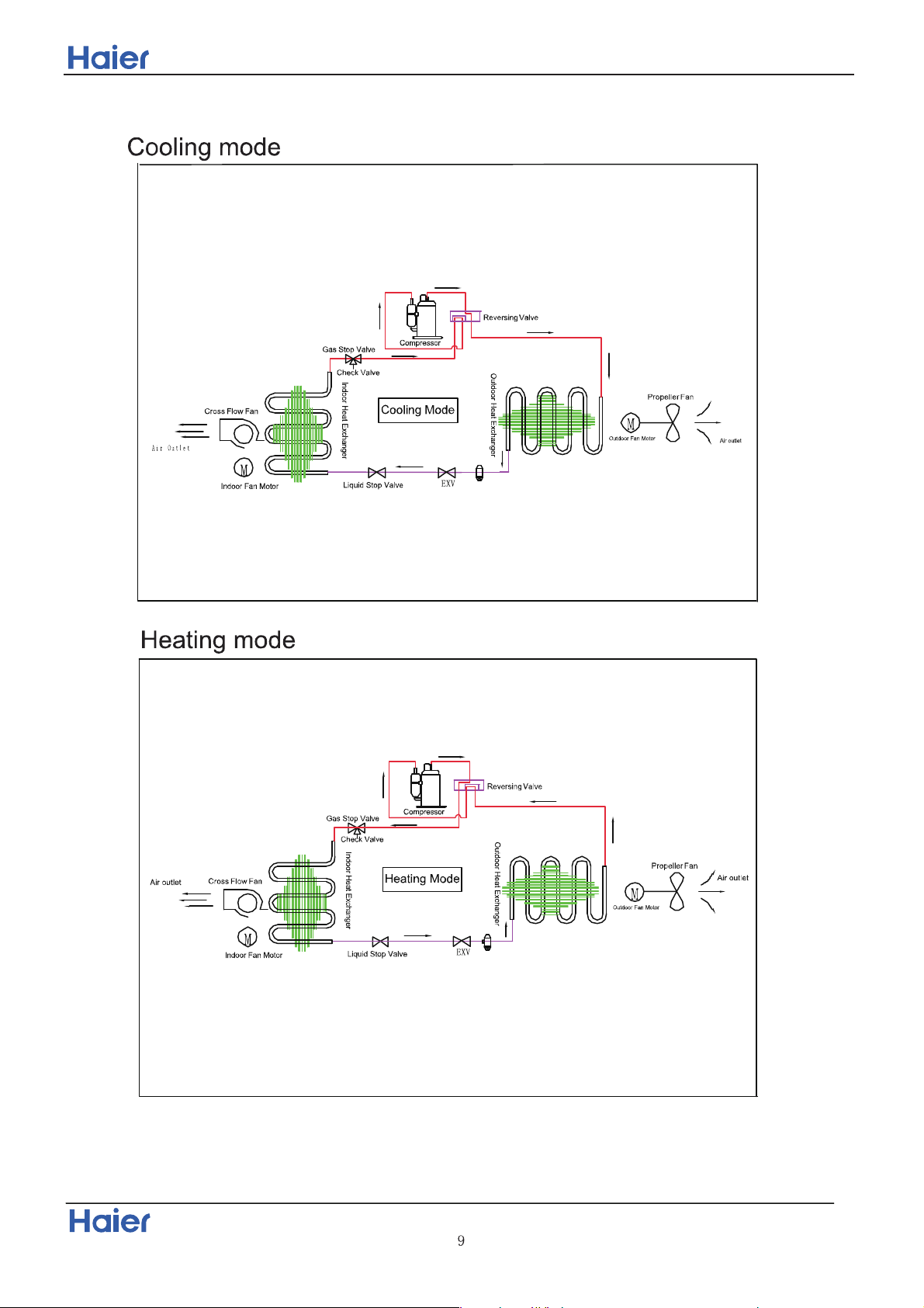
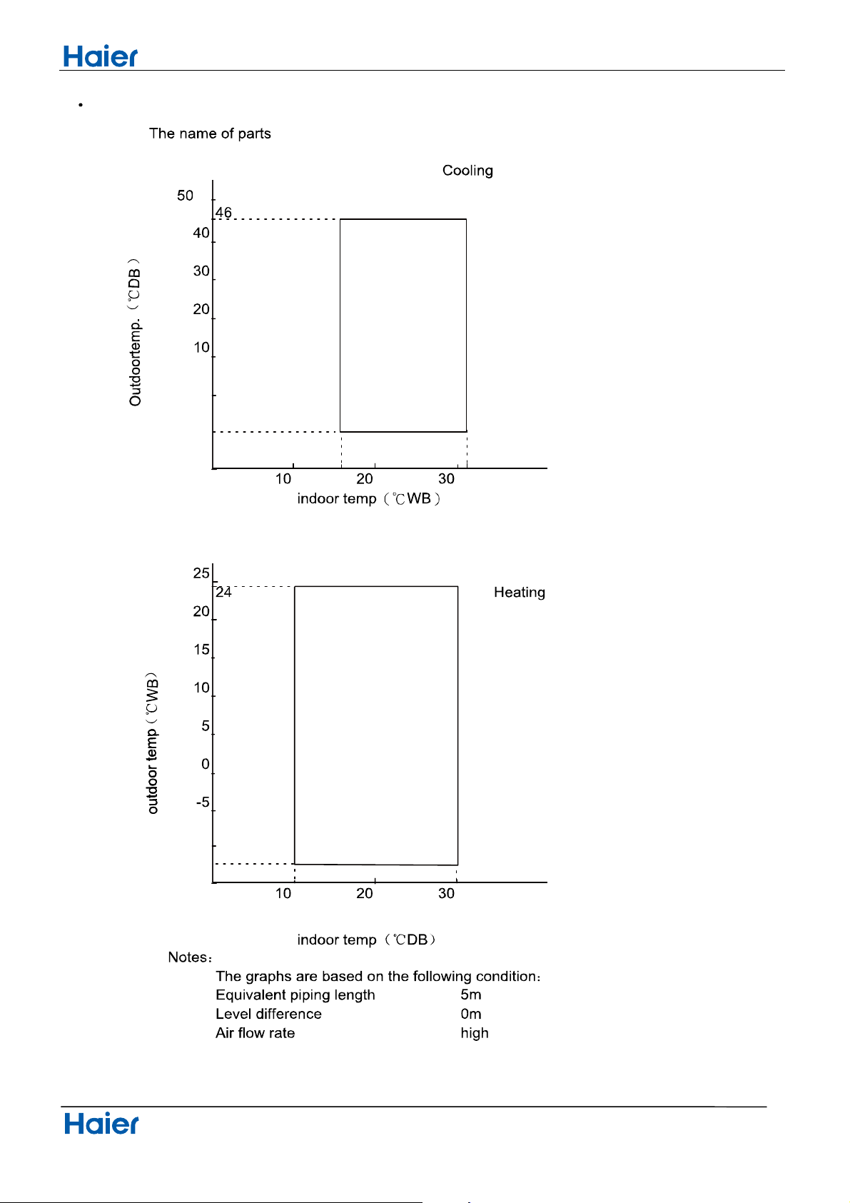
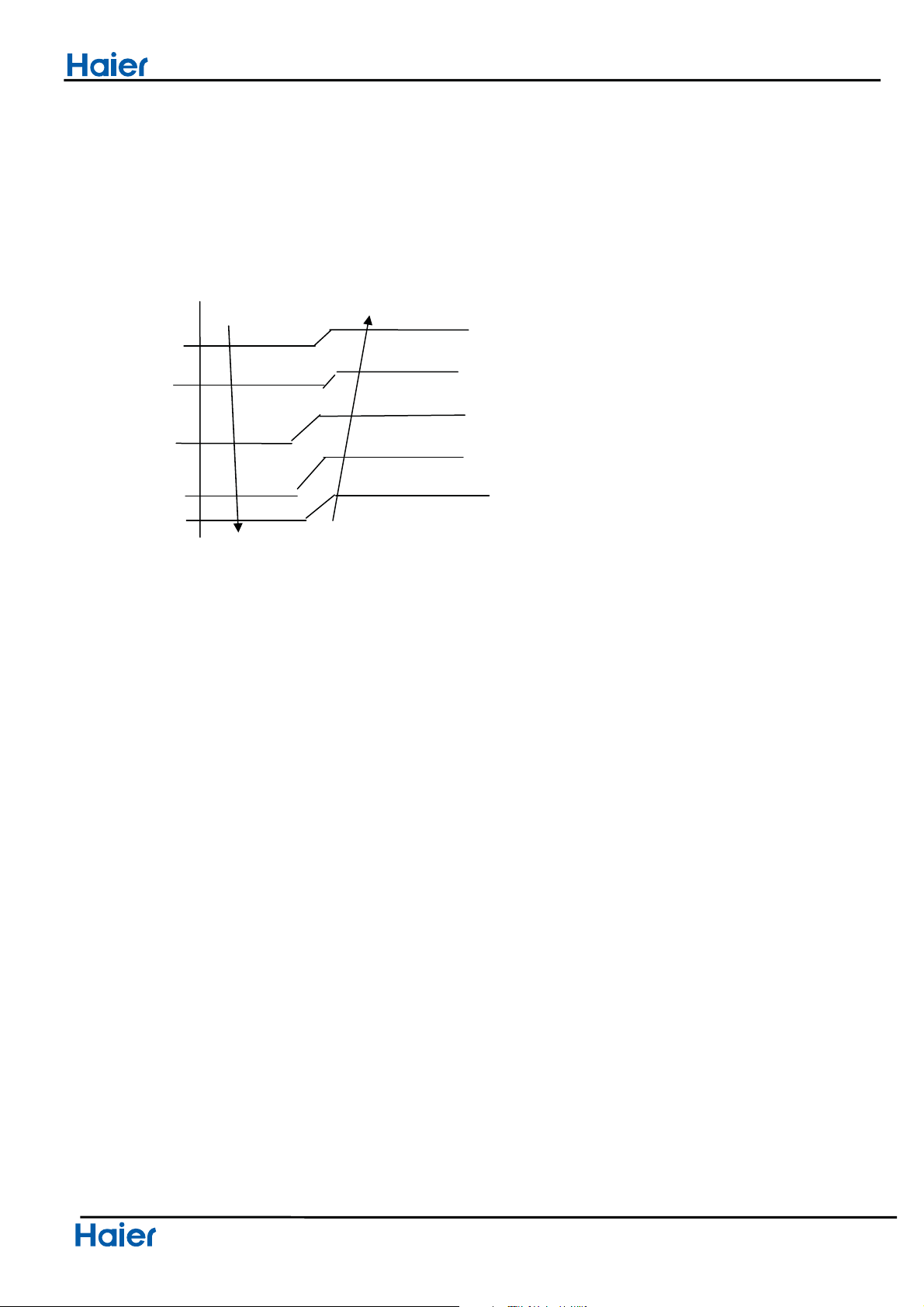
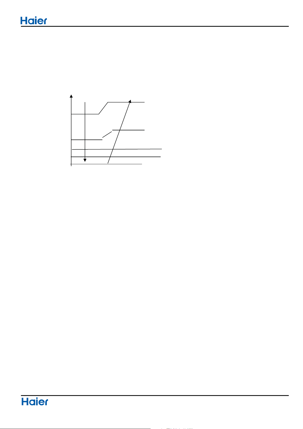
5 Operation range
-10
0
-20
16
32
-10
-20
-15
10
Wiring diagrams
Domestic air conditioner
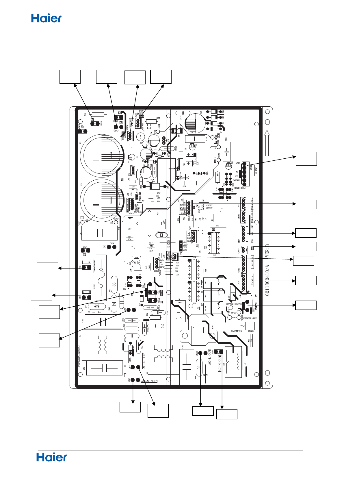
6.PCB Diagram
11
Connectors
PCB (1) (Outdoor Control PCB)
1) CN1, CN2 Connector for power N and L
2) CN3 Connector for ground
3) CN23 Connector for DC POWER 15Vand 5V to the module board
4) CN9, CN10 Connector for CN2,CN1 on the module board
5) CN22 Connector for fan motor
6) CN11 Connector for four way valve coil
7) CN17, CN47 Connector for thermistors
8) CN24 Connector for communicate between the control board and the module board
9) CN26, CN25 Connector to P and N of the module board
10) CN36 Connector for communicate between indoor and outdoor unit
11) CN15 Connector for electric expansion valves
12) CN50 Connector for DRED-control
13) CN45 Connector for heating- protect wire of terminal block
Other Designations
1) FUSE 1, (25A, 250VAC); FUSE 2(3.15A, 250VAC)
2) LED 1 Keep light representative normal, if keep flash interval representative trouble Alarm
3) RV1, RV2, RV3 Varistor
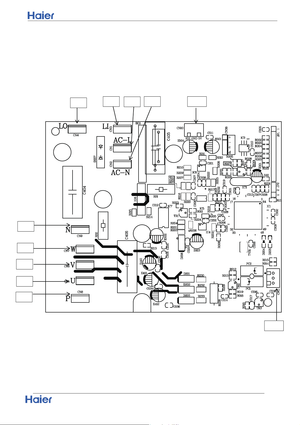
PCB (2) (Module PCB )
CN10 Connector for the DC power 5V and 15V form the control PCB
CN11 Connector for communicate between the control board and the module board
P (CN8), N (CN9) Connector for capacitance board
LI (CN3), LO (CN4) Connector for reactor
CN5, CN6, CN7Connector for the U, V, W wire of the compressor
Connector Wiring Diagram
Domestic Air Conditioner
12
PCB (1)
CN1
CN2
CN36
CN24
CN10
CN9
CN22
CN11
CN17
CN50
CN47
CN23CN25 CN28
CN3
CN15
CN7
CN6
CN45
CN4
CN3 CN10
CN1
CN2
CN9
CN7
CN6
CN5
CN8
CN11
Connector Wiring Diagram
Domestic Air Conditioner
13
PCB (2)
Functions and control
Domestic air conditioner
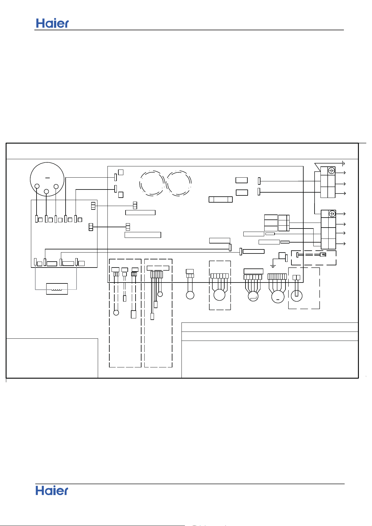
Wiring diagrams
14
THE CAPACITOR RETAINS HIGH VOLTAGE EVEN AFTER THE PLUG-OFF. FOR YOUR
●
SAFETY, BE SURE TO WAIT AT LEAST 5 MINUTES.AFTER PLUG OFF AND USE A
TESTER TO CONFIRM THE VOLTAGE BETWEEN CONNECTOR CN25 AND CN28(ON MAIN
PCB BOARD) IS LESS THAN DC 10V BEFORE START SERVICING OR LED2
EXTINGUISHED.
Note:The dotted parts are optional.
The @1 and the @2 cannot exist at the time,
but must keep one of them.
B: Black W: White
R: Red Y/G: Yellow/Green
BR: Brown OR: Orange
BL:
Blue GR:Gray
DON'T TOUCH CAPACITOR, EVEN AFTER PLUG-OFF ( DANGER OF ELECTRIC SHOCK)!
COMPRESSOR
OUTDOOR UNIT WIRING DIAGRAM
M
AC-N OUT
●
ELECTRIC
EXPANSION
WARNING
●
CAUTION
AC-N OUT
AC-L OUT
AMBIENT TEMP.SENSOR
TEMP.SENSOR
COMP.TEMP.SENSOR
TEMP.SENSOR
TEMP.SENSOR
DEFROST
@1
DEFROST
COMP.TEMP.SENSOR
@2
AMBIENT
BL
OR
CN3
CN1
CN4
CN2
AC-N
REACTOR
GR
LI
AC-L
GR
L0
MOUDLE PCB
CN5
CN6
CN7
W
U
B
V
W
R
CN8
CN9
BL
CN10
P N
CN11
B
S(V)
R(U)
C(W)
CN1
AC-N
FUSE1
N
OUTDOOR PCB
TEMP.SENSOR
SUCTION
CS
CN18
HW
CN19
TC
CN17
HW
CN17
TC
CS
CN24
MODULE COM
MODULE POWER
CN23
BL
B
BL(OR W)
BR(OR B)
AC FAN
MOTOR
CN43
AC FAN
M
~
CN47
XQ
VALVE
M
VALVE A
CN15
CN10
AC-L OUT
T25A 250VAC
CN9
CAP
CN25
CN28
P
CAP
AC-L
CN2
1(N)
●
PE
Y/G
CN50
4-WAY VALVE
DC FAN
MOTOR
M
CN22
CN3
CN11
DRED LINE
BL(OR W)
BR(OR B)
BL(OR W)
N
CN6
CN7
CN36
COMB
COMA
R
3(C)
1
2
Y/G
TO INDOOR UNIT
0010534175A
BL(OR W)
BR(OR B)
2(L)
Y/G
POWER
Functions and control
Domestic air conditioner
7. Functions and Control
7.1 Main functions and control specification
7.1.1 The operation frequency of outdoor unit and its control
7.1.1.1 The operation frequency control of compressor
7.1.1.2 The starting of compressor
7.1.1.3 The speeds of increasing or decreasing the frequency of the compressor
7.1.1.4 The calculation of the compressor’s frequency
15
The operation frequency scope of compressor˖
Mode Minimun operation frequency Maximun operation frequency
zH811 zH02 gnitaeH
zH09 zH 02 noitaregirfeR
When the compressor is started for the first time, it must be kept under the conditions of 58Hz,88Hz for
one minute (the overheating protection of the outdoor unit air-blowing temperature, immediately decrease the
frequency when the compressor is overflowing and releasing the pressure)ˈthen it can be operated towards
the target frequency. When the machine runs normally, there’s no such process. After starting the
compressor for operation, the compressor should run according to the calculated frequency, and every
determined frequency for protection should be prior to the calculated frequency.
The speed of increasing or decreasing the frequency rapidly 1 -----------1HZ/second
The speed of increasing or decreasing the frequency slowly 2 -----------1HZ/10seconds
1˅ǃThe minimum/maximum frequency limitation
AˊWhile refrigerating: ˢˉ˩˝˴ˉ is the maximum operation frequency of the compressor; ˢˉ˩
INˉ is the minimum operation frequency of the compressor.
BˊWhile heating: ˢˉ˩˝˴ˉ is the maximum operation frequency of the compressor; ˢˉ˩INˉ
is the minimum operation frequency of the compressor.
1˅ǃThe frequency limitation which is affected by the environment temperature.
Heating mode:
Serial No. Temperature scope Frequency limitation
1 Wh_c<-12 Max_hz8 117 HZ
ZH7 11 7zh_xaM 8-<c_hW 2
ZH 711 4zh_xaM 2-<c_hW 3
ZH99 5zh_xaM 5<c_hW 4
ZH09 1zh_xaM 01<c_hW 5
ZH 72 2zh_xaM 71<c_hW 6
ZH 26 2zh_xaM 02<c_hW 7
8
Wh_c
≥20
Max_hz6 45 HZ
Remarks: the above are the maximum frequency limitations of the complete appliance which are affected by
the environment, and they have nothing to do with the ability of the indoor unit.
Refrigeration/dehumidification mode::
Serial No. Temperature scope Frequency limitation
ZH 83 1zh_xaM 61<c_hW 1
ZH 44 1zh_xaM 22<c_hW 1
ZH 55 1zh_xaM 82<c_hW 1
Functions and control
Domestic air conditioner
16
ZH472zh_xaM23<c_hW2
3
Wh_c
≥40
Max_hz3 90 HZ
Remarks: the above are not only the maximum frequency limitations of the complete appliance which are
affected by the environment, but also the maximum ability limitation of the system. When the starting ability is
not the maximum, its maximum frequency limitation is calculated by the following equations:
The frequency limitation which is affected by the temperature and under the condition of actual ability˙the
actural running system ability*the maximum frequency which is limited by the temperature and under the
condition of maximum ability/the maximum designing ability of the system
T=ě˄Ti*Pi˅/ěPi (Ti=|Tst_i-Tnh_i the indoor environment temperature| ;Pi˙i the ability of the
indoor unit)
Refrigeration/dehumidification:
Heating mode˖
K=ěKi/the number of running machines
The calculation of the actual output frequency: when there is no healthy airflow: F =F-ED-*hPhK
When the healthy airflow has been set: F =F-ED-*hPhK˄airflow speed˅hK˄healthy airflow˅
When refrigerating, it is needed to satisfy ˢˉ˩INˉ<F<ˢˉ˩˝˴ˉ
When heating, it is needed to satisfy ˢˉ˩INˉr< F<ˢˉ˩˝˴ˉr
7.1.2˖The outdoor fan control (exchange fan)
When the fan is changed among every airflow speed (including stop blowing), in order to avoid the airflow
speed from skipping frequently, it must be kept under each mode for over 30 seconds, and then it can be
changed to another mode (when refrigerating, the time is changed to 15 seconds).
7.1.2.1˖The outdoor fan control when refrigerating or dehumidifying
T
<1
˙1 ˙2 ˙3
≥
4
The percentage of the
rated frequency P
70% 80% 85% 90% 100%
T
<1
˙1 ˙2 ˙3
≥
4
The percentage of the
rated frequency P
70% 80% 85% 90% 100%
The indoor set airflow
speed
Low Medium High Strong Quiet Healthy
airflow
The percentage of the
rated
frequency Ki
80% 90% 100% 110% 70% 65%
ZH864zh_xaM84<c_hW4
5
Wh_c
≥48
Max_hz5 60 HZ
Functions and control
7.1.3˖The control of the outdoor electronic expansion valve
When starting the compressor: the opening size of the valve must be guaranteed to have entered into the
standard opening size, and then the compressor can be started.
When refrigeration is in vain (the machine is shut down or is in the state of retrograde operation), the opening
size of the expansion valve of the indoor unit is 5 steps;
When heating is in vain, the opening size of the expansion valve of the indoor unit is 55 steps;
When the outdoor unit is shut down, the valve is opened completely for 2 minutes, and then begin
initialization.
The scope of refrigerationg valve 90-----480 steps
The scope of heating valve 60-----480 steps
The valves are adjusted according to the degree of superheat —SHaˈƸSHa.
7.1.4˖Four way control
For the details of defrosting four-way valve control, see the defrosting process.
Four way working in other ways:
Under the mode of heating, open the four-way valve, when the compressor is not started or changed to
non-heating mode, make sure the compressor is stoped for 2 minutes, and then close the four-way valve.
Domestic air conditioner
17
17
During the compressor is started for 3 seconds, the outdoor fan is controlled the airflow speed
according to the temperature conditions of the outdoor environment.
Tao˄ć˅ Tao <ćć Taoć Taoı29ć
7 leveL 5 leveL 3 leveL yrD/looC
Tao˄ć˅ Tao <ćć Taoć Taoıć
3 leveL 5 leveL 7 leveL taeH
After the compressor is started for 3 seconds, the outdoor fan is controlled the airflow speed
according to the temperature conditions of the outdoor environment and frequency of compressor.
Frequency of cooling mode
˄Hz˅ <51 51ī70 ı70
Tao˄ć˅
İ Level 3 Level 5 Level 6
22ī Level 4 Level 6 Level 7
ı
Level 7
Frequency of heat mode˄Hz˅ <51 51ī90 ı
Tao˄ć˅
İ
Level 5Level 7Level 7
10īLevel 4Level 5Level 5
!Level 2

Functions and control
7.1.5 ˖Protection function
7.1.5.1˖TTC high temperature-preventing protection
Once the machine is started, it can run TTC overheating protection of air-blowing, but air-blowing sensor
malfunction must alarm after 4 minutes during which the compressor is started (during the course of
self-detection, there’s no such limitation)
Sensor detection methods: 100 times (one cycle of procedure run is one time, and about 5ms, detection
method for each time: continuously sampling for 8 times, then order them and take the mean value of the
middle 2 values), take the mean value.
TTC˄ć˅
Abnormal stop
115
Decreasing the frequency rapidly˄1HZ/second˅
110
Decreasing the frequency slowly (1HZ/10seconds)
105
The frequency doesn’t change.
98
Increasing the frequency (1HZ/10second)
95
Increasing the frequency˄1HZ/1second˅
TTC>=115ć lasts for 20 seconds. Overheating protection of air-blowing, alarm malfunction to the indoor,
others don’t last.
Domestic air conditioner
18
Functions and control
7.1.5.3˖The protection function of AC current:
During the starting process of the compressor, if the AC current is greater than 12A, the frequency of the
compressor decreases at the speed of 1HZ/second.
During the starting process of the compressor, if the AC current is greater than 11A, the frequency of the
compressor decreases at the speed of 0.1HZ/second.
During the starting process of the compressor, if the AC current is greater than 10A, the frequency of the
compressor increases at the prohibited speed.
During the starting process of the compressor, if the AC current is greater than 9A, the frequency of the
compressor increases at the speed of no faster than 0.1HZ/second.
Remarks: when the outdoor temperature is high, there’s compensation for AC current protection.
ŁWhen the outdoor environment temperature is higher than 40ć, AC current protection value decreases
by 1.5A
łWhen the outdoor environment temperature is higher than 50ć,AC current protection value decreases by
3.5A
Domestic air conditioner
19
7.1.5.2˖TC high temperature-preventing control of the indoor heating unit
Tpg_indoor is the highest value of the effective indoor unit (start it and it is in accord with the running state).
The indoor heat exchanger sensor tests the temperature of the indoor heat exchanger. If the temperature is
higher than 48ć, decrease the rotate speed of the compressor and do the high temperature-preventing
protection of the indoor heat exchanger; if the temperature of the indoor heat exchanger is lower than 45ć,
recover to the normal control.
TC The compressor stops
Fgh_t1ˉ2 Fgh_t1 63ć
N Decreasing the frequency rapidly Fgh_t2 59ć
Fgh_t2ˉ2 P Decreasing the frequency slowly
Fgh_t3 55ć
Fgh_t3ˉ2 Q Prohibiting increasing the frequency
Fgh_t4 51ć
Fgh_t4—2 R Increasing slowly Fgh_t5 47ć
Fgh_t5—2
Normal
N˖Decreasing at the speed of 1HZ/1second
P˖Decreasing at the speed of 1Hz/10seconds
Q˖Continue to keep the last-time instruction cycle
R˖Increasing at the speed of 1Hz/10seconds
Remarks: the outdoor unit
Functions and control
When Tpg_indoor begins to rise again, and ice_temp_2İTpg_indoorİ ice_temp_3ć, the frequency of
thecompressor doesn’t change.
When ice_temp_3LJTpg_indoorLJice_temp_4ć, the frequency of the compressor increases at the speed of
1HZ/10seconds.
For example, Tpg_indoorİ0ćˈlast for 2 minutes, and then the outdoor unit will stop, and report underload
malfunction, but don’t send malfunction report to the indoor.
The compressor stops for more than 3 minutes, Tpg_indoor> ice_temp_4ć, the compressor recovers.
Domestic air conditioner
20
7.1.5.4˖Antifreezing protection of the indoor heat exchanger
When refrigerating/heating, prevent freezing.
Tpg_indoor is the minimum value of the effective indoor unit (start it and it is in accord with the running state).
11ć//ice_temp_4+2
9ć
ice_temp_4 Increasing slowly
9ć//ice_temp_3+2
Keeping the frequency
ice_temp_3 7ć 6ć
ice_temp_2 5ć Decreasingslowly
ice_temp_1 3ć Decreasing rapidly ice_temp_1
0ć Stop
When Tpg_indoor LJice_temp_1 ć, the frequency of the compressor decreases at the speed of
1HZ/1second.
When Tpg_indoor LJice_temp_2 ć, the frequency of the compressor decreases at the speed of
1HZ/10seconds.

Functions and control
7.2 Value of Thermistor
Domestic air conditioner
7.2.1 Outdoor Unit
Ambient Sensor, Defrosting Sensor, Pipe sensor
R25ć=10K¡f3% B25ć/50ć=3700Kf3%
Temp.(ć)
Max.(KΩ) Normal(KΩ) Min.(KΩ)
Tolerance(ć)
-30 165.2170 147.9497 132.3678 -1.94 1.75
-29 155.5754 139.5600 125.0806 -1.93 1.74
-28 146.5609 131.7022 118.2434 -1.91 1.73
-27 138.1285 124.3392 111.8256 -1.89 1.71
21
7.1.5.5˖Temperature protection of the outdoor refrigerating coil
When the defrosting temperature and the sensor’s temperature are higher than 68ć, the frequency of the
compressor decreases 1hz/10seconds. Keep the frequency until it decreases to the lowest frequency. When
the temperatures are lower than 68ć and higher than 61ć, keep the frequency of the compressor. When
the temperatures are lower than 61ć, relieve the defrosting temperature protection.
Functions and control
-26 130.2371 117.4366 105.7989 -1.87 1.70
-25 122.8484 110.9627 100.1367 -1.85 1.69
-24 115.9272 104.8882 94.8149 -1.83 1.67
-23 109.4410 99.1858 89.8106 -1.81 1.66
-22 103.3598 93.8305 85.1031 -1.80 1.64
-21 97.6556 88.7989 80.6728 -1.78 1.63
-20 92.3028 84.0695 76.5017 -1.76 1.62
-19 87.2775 79.6222 72.5729 -1.74 1.60
-18 82.5577 75.4384 68.8710 -1.72 1.59
-17 78.1230 71.5010 65.3815 -1.70 1.57
-16 73.9543 67.7939 62.0907 -1.68 1.55
-15 70.0342 64.3023 58.9863 -1.66 1.54
-14 66.3463 61.0123 56.0565 -1.64 1.52
-13 62.8755 57.9110 53.2905 -1.62 1.51
-12 59.6076 54.9866 50.6781 -1.60 1.49
-11 56.5296 52.2278 48.2099 -1.58 1.47
-10 53.6294 49.6244 45.8771 -1.56 1.46
-9 50.8956 47.1666 43.6714 -1.54 1.44
-8 48.3178 44.8454 41.5851 -1.51 1.42
-7 45.8860 42.6525 39.6112 -1.49 1.40
-6 43.5912 40.5800 37.7429 -1.47 1.39
-5 41.4249 38.6207 35.9739 -1.45 1.37
-4 39.3792 36.7676 34.2983 -1.43 1.35
-3 37.4465 35.0144 32.7108 -1.41 1.33
-2 35.6202 33.3552 31.2062 -1.38 1.31
-1 33.8936 31.7844 29.7796 -1.36 1.29
0 32.2608 30.2968 28.4267 -1.34 1.28
1 30.7162 28.8875 27.1431 -1.32 1.26
2 29.2545 27.5519 25.9250 -1.29 1.24
3 27.8708 26.2858 24.7686 -1.27 1.22
4 26.5605 25.0851 23.6704 -1.25 1.20
5 25.3193 23.9462 22.6273 -1.23 1.18
6 24.1432 22.8656 21.6361 -1.20 1.16
7 23.0284 21.8398 20.6939 -1.18 1.14
8 21.9714 20.8659 19.7982 -1.15 1.12
9 20.9688 19.9409 18.9463 -1.13 1.09
10 20.0176 19.0621 18.1358 -1.11 1.07
11 19.1149 18.2270 17.3646 -1.08 1.05
12 18.2580 17.4331 16.6305 -1.06 1.03
13 17.4442 16.6782 15.9315 -1.03 1.01
14 16.6711 15.9601 15.2657 -1.01 0.99
15 15.9366 15.2770 14.6315 -0.98 0.96
16 15.2385 14.6268 14.0271 -0.96 0.94
17 14.5748 14.0079 13.4510 -0.93 0.92
18 13.9436 13.4185 12.9017 -0.91 0.90
Domestic air conditioner
22
Functions and control
19 13.3431 12.8572 12.3778 -0.88 0.87
20 12.7718 12.3223 11.8780 -0.86 0.85
21 12.2280 11.8126 11.4011 -0.83 0.83
22 11.7102 11.3267 10.9459 -0.81 0.80
23 11.2172 10.8634 10.5114 -0.78 0.78
24 10.7475 10.4216 10.0964 -0.75 0.75
25 10.3000 10.0000 9.7000 -0.75 0.75
26 9.8975 9.5974 9.2980 -0.76 0.76
27 9.5129 9.2132 8.9148 -0.80 0.80
28 9.1454 8.8465 8.5496 -0.84 0.83
29 8.7942 8.4964 8.2013 -0.87 0.86
30 8.4583 8.1621 7.8691 -0.91 0.90
31 8.1371 7.8428 7.5522 -0.95 0.93
32 7.8299 7.5377 7.2498 -0.98 0.97
33 7.5359 7.2461 6.9611 -1.02 1.00
34 7.2546 6.9673 6.6854 -1.06 1.04
35 6.9852 6.7008 6.4222 -1.10 1.07
36 6.7273 6.4459 6.1707 -1.13 1.11
37 6.4803 6.2021 5.9304 -1.17 1.14
38 6.2437 5.9687 5.7007 -1.21 1.18
39 6.0170 5.7454 5.4812 -1.25 1.22
40 5.7997 5.5316 5.2712 -1.29 1.25
41 5.5914 5.3269 5.0704 -1.33 1.29
42 5.3916 5.1308 4.8783 -1.37 1.33
43 5.2001 4.9430 4.6944 -1.41 1.36
44 5.0163 4.7630 4.5185 -1.45 1.40
45 4.8400 4.5905 4.3500 -1.49 1.44
46 4.6708 4.4252 4.1887 -1.53 1.47
47 4.5083 4.2666 4.0342 -1.57 1.51
48 4.3524 4.1145 3.8862 -1.61 1.55
49 4.2026 3.9686 3.7443 -1.65 1.59
50 4.0588 3.8287 3.6084 -1.70 1.62
51 3.9206 3.6943 3.4780 -1.74 1.66
52 3.7878 3.5654 3.3531 -1.78 1.70
53 3.6601 3.4416 3.2332 -1.82 1.74
54 3.5374 3.3227 3.1183 -1.87 1.78
55 3.4195 3.2085 3.0079 -1.91 1.82
56 3.3060 3.0989 2.9021 -1.95 1.85
57 3.1969 2.9935 2.8005 -2.00 1.89
58 3.0919 2.8922 2.7029 -2.04 1.93
59 2.9909 2.7948 2.6092 -2.08 1.97
60 2.8936 2.7012 2.5193 -2.13 2.01
61 2.8000 2.6112 2.4328 -2.17 2.05
62 2.7099 2.5246 2.3498 -2.22 2.09
63 2.6232 2.4413 2.2700 -2.26 2.13
Domestic air conditioner
23
Functions and control
64 2.5396 2.3611 2.1932 -2.31 2.17
65 2.4591 2.2840 2.1195 -2.36 2.21
66 2.3815 2.2098 2.0486 -2.40 2.25
67 2.3068 2.1383 1.9803 -2.45 2.29
68 2.2347 2.0695 1.9147 -2.49 2.34
69 2.1652 2.0032 1.8516 -2.54 2.38
70 2.0983 1.9393 1.7908 -2.59 2.42
71 2.0337 1.8778 1.7324 -2.63 2.46
72 1.9714 1.8186 1.6761 -2.68 2.50
73 1.9113 1.7614 1.6219 -2.73 2.54
74 1.8533 1.7064 1.5697 -2.78 2.58
75 1.7974 1.6533 1.5194 -2.83 2.63
76 1.7434 1.6021 1.4710 -2.88 2.67
77 1.6913 1.5528 1.4243 -2.92 2.71
78 1.6409 1.5051 1.3794 -2.97 2.75
79 1.5923 1.4592 1.3360 -3.02 2.80
80 1.5454 1.4149 1.2942 -3.07 2.84
81 1.5000 1.3721 1.2540 -3.12 2.88
82 1.4562 1.3308 1.2151 -3.17 2.93
83 1.4139 1.2910 1.1776 -3.22 2.97
84 1.3730 1.2525 1.1415 -3.27 3.01
85 1.3335 1.2153 1.1066 -3.32 3.06
86 1.2953 1.1794 1.0730 -3.38 3.10
87 1.2583 1.1448 1.0405 -3.43 3.15
88 1.2226 1.1113 1.0092 -3.48 3.19
89 1.1880 1.0789 0.9789 -3.53 3.24
90 1.1546 1.0476 0.9497 -3.58 3.28
91 1.1223 1.0174 0.9215 -3.64 3.33
92 1.0910 0.9882 0.8942 -3.69 3.37
93 1.0607 0.9599 0.8679 -3.74 3.42
94 1.0314 0.9326 0.8424 -3.80 3.46
95 1.0030 0.9061 0.8179 -3.85 3.51
96 0.9756 0.8806 0.7941 -3.90 3.55
97 0.9490 0.8558 0.7711 -3.96 3.60
98 0.9232 0.8319 0.7489 -4.01 3.64
99 0.8983 0.8088 0.7275 -4.07 3.69
100 0.8741 0.7863 0.7067 -4.12 3.74
101 0.8507 0.7646 0.6867 -4.18 3.78
102 0.8281 0.7436 0.6672 -4.23 3.83
103 0.8061 0.7233 0.6484 -4.29 3.88
104 0.7848 0.7036 0.6303 -4.34 3.92
105 0.7641 0.6845 0.6127 -4.40 3.97
106 0.7441 0.6661 0.5957 -4.46 4.02
107 0.7247 0.6482 0.5792 -4.51 4.07
108 0.7059 0.6308 0.5632 -4.57 4.12
Domestic air conditioner
24
Functions and control
109 0.6877 0.6140 0.5478 -4.63 4.16
110 0.6700 0.5977 0.5328 -4.69 4.21
111 0.6528 0.5820 0.5183 -4.74 4.26
112 0.6361 0.5667 0.5043 -4.80 4.31
113 0.6200 0.5518 0.4907 -4.86 4.36
114 0.6043 0.5374 0.4775 -4.92 4.41
115 0.5891 0.5235 0.4648 -4.98 4.45
116 0.5743 0.5100 0.4524 -5.04 4.50
117 0.5600 0.4968 0.4404 -5.10 4.55
118 0.5460 0.4841 0.4288 -5.16 4.60
119 0.5325 0.4717 0.4175 -5.22 4.65
120 0.5194 0.4597 0.4066 -5.28 4.70
Discharging Sensor
R80ć=50K¡f3%
B25/80ć=4450Kf3%
Temp.((ć))
Max.(KΩ) Normal(KΩ) Min.(KΩ)
Tolerance(ć)
-30 14646.0505 12061.7438 9924.4999 -2.96 2.45
-29 13654.1707 11267.8730 9290.2526 -2.95 2.44
-28 12735.8378 10531.3695 8700.6388 -2.93 2.44
-27 11885.1336 9847.7240 8152.2338 -2.92 2.43
-26 11096.6531 9212.8101 7641.8972 -2.91 2.42
-25 10365.4565 8622.8491 7166.7474 -2.90 2.42
-24 9687.0270 8074.3787 6724.1389 -2.88 2.41
-23 9057.2314 7564.2244 6311.6413 -2.87 2.41
-22 8472.2852 7089.4741 5927.0206 -2.86 2.40
-21 7928.7217 6647.4547 5568.2222 -2.84 2.39
-20 7423.3626 6235.7109 5233.3554 -2.83 2.39
-19 6953.2930 5851.9864 4920.6791 -2.82 2.38
-18 6515.8375 5494.2064 4628.5894 -2.80 2.37
-17 6108.5393 5160.4621 4355.6078 -2.79 2.37
-16 5729.1413 4848.9963 4100.3708 -2.77 2.36
-15 5375.5683 4558.1906 3861.6201 -2.76 2.35
-14 5045.9114 4286.5535 3638.1938 -2.75 2.34
-13 4738.4141 4032.7098 3429.0191 -2.73 2.34
-12 4451.4586 3795.3910 3233.1039 -2.72 2.33
-11 4183.5548 3573.4260 3049.5312 -2.70 2.32
-10 3933.3289 3365.7336 2877.4527 -2.69 2.31
-9 3699.5139 3171.3148 2716.0828 -2.67 2.30
-8 3480.9407 2989.2460 2564.6945 -2.66 2.29
-7 3276.5302 2818.6731 2422.6139 -2.64 2.28
-6 3085.2854 2658.8058 2289.2164 -2.63 2.28
-5 2906.2851 2508.9126 2163.9230 -2.61 2.27
-4 2738.6777 2368.3158 2046.1961 -2.60 2.26
-3 2581.6752 2236.3876 1935.5371 -2.58 2.25
Domestic air conditioner
25
Functions and control
-2 2434.5487 2112.5459 1831.4826 -2.56 2.24
-1 2296.6230 1996.2509 1733.6024 -2.55 2.23
0 2167.2730 1887.0018 1641.4966 -2.53 2.22
1 2045.9191 1784.3336 1554.7931 -2.52 2.21
2 1932.0242 1687.8144 1473.1460 -2.50 2.20
3 1825.0899 1597.0431 1396.2333 -2.48 2.19
4 1724.6540 1511.6468 1323.7551 -2.47 2.17
5 1630.2870 1431.2787 1255.4324 -2.45 2.16
6 1541.5904 1355.6163 1191.0048 -2.43 2.15
7 1458.1938 1284.3593 1130.2298 -2.41 2.14
8 1379.7528 1217.2282 1072.8813 -2.40 2.13
9 1305.9472 1153.9626 1018.7481 -2.38 2.12
10 1236.4792 1094.3200 967.6334 -2.36 2.11
11 1171.0715 1038.0743 919.3533 -2.35 2.09
12 1109.4661 985.0146 873.7359 -2.33 2.08
13 1051.4226 934.9440 830.6210 -2.31 2.07
14 996.7169 887.6792 789.8583 -2.29 2.06
15 945.1404 843.0486 751.3077 -2.27 2.04
16 896.4981 800.8922 714.8380 -2.26 2.03
17 850.6086 761.0603 680.3265 -2.24 2.02
18 807.3024 723.4134 647.6580 -2.22 2.00
19 766.4212 687.8205 616.7252 -2.20 1.99
20 727.8172 654.1596 587.4271 -2.18 1.98
21 691.3524 622.3161 559.6694 -2.16 1.96
22 656.8979 592.1831 533.3634 -2.14 1.95
23 624.3328 563.6604 508.4261 -2.12 1.93
24 593.5446 536.6540 484.7796 -2.10 1.92
25 564.4275 511.0760 462.3510 -2.09 1.90
26 536.9865 486.9352 441.1516 -2.07 1.89
27 511.0105 464.0500 421.0258 -2.05 1.87
28 486.4151 442.3499 401.9146 -2.03 1.86
29 463.1208 421.7683 383.7626 -2.01 1.84
30 441.0535 402.2430 366.5175 -1.99 1.83
31 420.1431 383.7151 350.1301 -1.97 1.81
32 400.3242 366.1295 334.5542 -1.95 1.80
33 381.5350 349.4341 319.7460 -1.93 1.78
34 363.7176 333.5801 305.6645 -1.90 1.76
35 346.8176 318.5216 292.2709 -1.88 1.75
36 330.7839 304.2151 279.5286 -1.86 1.73
37 315.5682 290.6199 267.4031 -1.84 1.71
38 301.1254 277.6976 255.8620 -1.82 1.70
39 287.4128 265.4119 244.8745 -1.80 1.68
40 274.3905 253.7288 234.4118 -1.78 1.66
41 262.0206 242.6161 224.4465 -1.76 1.64
42 250.2676 232.0436 214.9529 -1.74 1.63
Domestic air conditioner
26
Functions and control
43 239.0983 221.9825 205.9065 -1.71 1.61
44 228.4809 212.4060 197.2844 -1.69 1.59
45 218.3860 203.2887 189.0648 -1.67 1.57
46 208.7855 194.6066 181.2273 -1.65 1.55
47 199.6531 186.3369 173.7524 -1.63 1.54
48 190.9639 178.4584 166.6217 -1.60 1.52
49 182.6945 170.9508 159.8181 -1.58 1.50
50 174.8228 163.7951 153.3249 -1.56 1.48
51 167.3280 156.9733 147.1268 -1.53 1.46
52 160.1904 150.4683 141.2090 -1.51 1.44
53 153.3914 144.2641 135.5577 -1.49 1.42
54 146.9136 138.3454 130.1598 -1.47 1.40
55 140.7403 132.6980 125.0027 -1.44 1.38
56 134.8559 127.3081 120.0746 -1.42 1.36
57 129.2457 122.1630 115.3645 -1.40 1.34
58 123.8956 117.2504 110.8618 -1.37 1.32
59 118.7926 112.5589 106.5564 -1.35 1.30
60 113.9241 108.0776 102.4388 -1.32 1.28
61 109.2784 103.7961 98.5000 -1.30 1.26
62 104.8443 99.7046 94.7315 -1.28 1.23
63 100.6112 95.7939 91.1253 -1.25 1.21
64 96.5692 92.0553 87.6735 -1.23 1.19
65 92.7088 88.4805 84.3690 -1.20 1.17
66 89.0211 85.0614 81.2048 -1.18 1.15
67 85.4976 81.7908 78.1744 -1.15 1.12
68 82.1303 78.6615 75.2715 -1.13 1.10
69 78.9116 75.6668 72.4902 -1.10 1.08
70 75.8343 72.8004 69.8249 -1.08 1.06
71 72.8916 70.0561 67.2703 -1.05 1.03
72 70.0770 67.4283 64.8213 -1.03 1.01
73 67.3844 64.9115 62.4731 -1.00 0.99
74 64.8080 62.5006 60.2211 -0.98 0.96
75 62.3423 60.1906 58.0609 -0.95 0.94
76 59.9821 57.9770 55.9885 -0.92 0.92
77 57.7223 55.8552 53.9998 -0.90 0.89
78 55.5583 53.8210 52.0912 -0.87 0.87
79 53.4856 51.8706 50.2591 -0.85 0.84
80 51.5000 50.0000 48.5000 -0.85 0.84
81 49.7063 48.2057 46.7083 -0.85 0.85
82 47.9835 46.4842 44.9911 -0.89 0.89
83 46.3286 44.8323 43.3452 -0.93 0.92
84 44.7385 43.2468 41.7672 -0.96 0.95
85 43.2105 41.7248 40.2540 -1.00 0.99
86 41.7386 40.2604 38.7996 -1.03 1.02
87 40.3241 38.8545 37.4048 -1.07 1.06
Domestic air conditioner
27
Functions and control
88 38.9643 37.5045 36.0668 -1.11 1.09
89 37.6569 36.2078 34.7831 -1.14 1.13
90 36.3996 34.9622 33.5513 -1.18 1.16
91 35.1903 33.7653 32.3689 -1.22 1.19
92 34.0269 32.6151 31.2338 -1.26 1.23
93 32.9075 31.5096 30.1438 -1.30 1.27
94 31.8302 30.4467 29.0970 -1.33 1.30
95 30.7933 29.4246 28.0915 -1.37 1.34
96 29.7950 28.4417 27.1254 -1.41 1.37
97 28.8337 27.4961 26.1970 -1.45 1.41
98 27.9078 26.5864 25.3048 -1.49 1.44
99 27.0160 25.7110 24.4470 -1.53 1.48
100 26.1569 24.8685 23.6222 -1.57 1.52
101 25.3290 24.0574 22.8291 -1.61 1.55
102 24.5311 23.2765 22.0662 -1.65 1.59
103 23.7620 22.5245 21.3323 -1.69 1.63
104 23.0205 21.8002 20.6261 -1.73 1.66
105 22.3055 21.1025 19.9465 -1.77 1.70
106 21.6159 20.4303 19.2924 -1.81 1.74
107 20.9508 19.7825 18.6626 -1.85 1.77
108 20.3091 19.1582 18.0563 -1.89 1.81
109 19.6899 18.5564 17.4723 -1.93 1.85
110 19.0924 17.9761 16.9098 -1.98 1.89
111 18.5157 17.4166 16.3680 -2.02 1.93
112 17.9590 16.8769 15.8458 -2.06 1.96
113 17.4214 16.3564 15.3427 -2.10 2.00
114 16.9023 15.8542 14.8577 -2.15 2.04
115 16.4010 15.3696 14.3902 -2.19 2.08
116 15.9167 14.9020 13.9394 -2.23 2.12
117 15.4489 14.4506 13.5047 -2.27 2.16
118 14.9968 14.0149 13.0855 -2.32 2.19
119 14.5599 13.5942 12.6811 -2.36 2.23
120 14.1376 13.1879 12.2909 -2.41 2.27
121 13.7294 12.7955 11.9144 -2.45 2.31
122 13.3347 12.4165 11.5510 -2.50 2.35
123 12.9531 12.0503 11.2003 -2.54 2.39
124 12.5840 11.6965 10.8617 -2.58 2.43
125 12.2270 11.3545 10.5348 -2.63 2.47
126 11.8817 11.0240 10.2191 -2.68 2.51
127 11.5475 10.7046 9.9142 -2.72 2.55
128 11.2242 10.3957 9.6197 -2.77 2.59
129 10.9112 10.0970 9.3352 -2.81 2.63
130 10.6084 9.8082 9.0602 -2.86 2.67
131 10.3151 9.5288 8.7945 -2.91 2.71
132 10.0312 9.2586 8.5378 -2.95 2.75
Domestic air conditioner
28
Functions and control
133 9.7563 8.9971 8.2895 -3.00 2.80
134 9.4901 8.7441 8.0495 -3.05 2.84
135 9.2322 8.4993 7.8175 -3.09 2.88
136 8.9824 8.2623 7.5931 -3.14 2.92
137 8.7404 8.0329 7.3760 -3.19 2.96
138 8.5059 7.8108 7.1660 -3.24 3.00
139 8.2787 7.5958 6.9629 -3.29 3.04
140 8.0584 7.3875 6.7664 -3.33 3.09
Domestic air conditioner
29

Dimensinal drawings
Domestic air conditioner
8.Dimensional drawings
9.Center of gravity
920
1018
762
385
385
920
12.7
3/4
920
288
762
374
385
132
30
Connector Wiring Diagram
Domestic Air Conditioner
1 .Service Diagnosis
1 .1.1 Caution for Diagnosis
The operation lamp flashes when any of the following errors is detected.
1.Whenaprotection device of the indoor or outdoor unit is activated or when the thermistor malfunctions,
disabling equipment operation.
2.Whenasignal transmission error occurs between the indoor and outdoor units.In either case, conduct the
diagnostic procedure described in the following pages.
31
1 .1.2 Problem Symptoms and Measures
erusaeMfosliateDmetIkcehCmotpmyS
None of the units
operates
Check the power supply. Check to make sure that the rated voltage is supplied.
Check the indoor PCB Check to make sure that the indoor PCB is broken
Operation
sometimes stops.
Check the power supply.
A power failure of2to 10 cycles can stop air conditioner
operation.
Equipment
operates but
does not cool, or
does not heat
(only for heat
pump)
Check for faulty operation
of the electronic
expansion valve.
Set the units to cooling operation, and compare the
temperatures of the liquid side connection pipes of the
connection section among rooms to check the opening and
closing operation of the electronic expansion valves of the
individual units.
Diagnosis by service port
pressure and operating
current.
Check for insufficient gas.
Large operating
noise and
vibrations
Check the installation
condition.
Check to make sure that the required spaces for
installation (specified in the Technical Guide, etc.) are
provided.
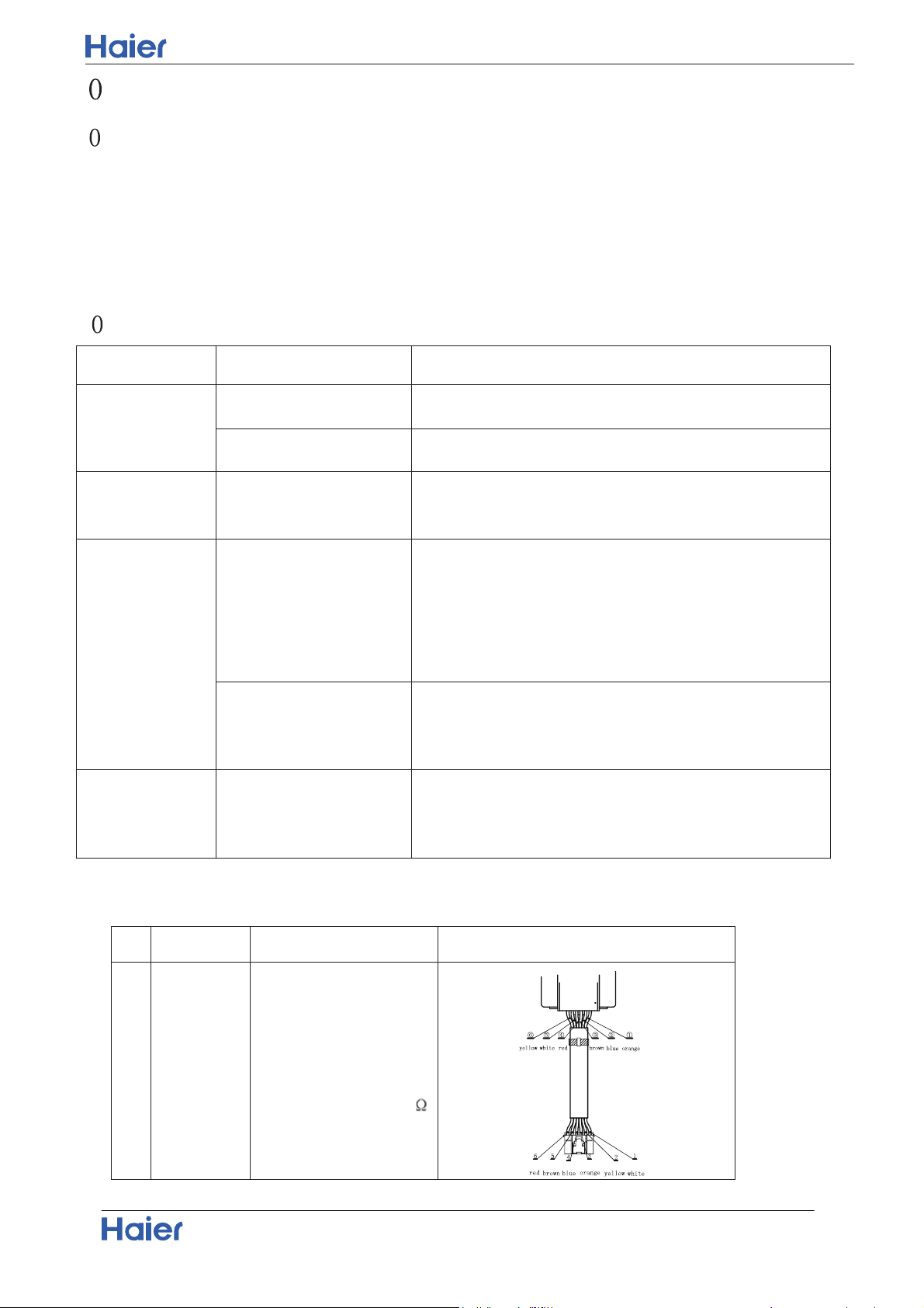
10.2 Parameter of primary electronic appliance
N O N am e Pa ra m eter Pic ture
1
Rated voltage:12V
ELECTRIC
EXPANSION
VALVE
Valve orifice : Φ1.8mm
Coil resistance 46±3.7
Connector Wiring Diagram
Domestic Air Conditioner
32
1 .3.1
Thermistor or Related Abnormality
1 .3 Error Codes and Description indoor display
Code indication
fault description
Indoor displaying panel code indication
Outdoor
(LED1
flash
times)
Other
display
Only For 498 and 498A display
(Red/Green Time Run □On ★
Flash ■Off ,)
Indoor and
Outdoor
E7 ■ ■ ★ 15
Communication fault between
indoor and outdoor units
Indoor
Malfunction
E1 ★ ■ ■ -- Room temperature sensor failure
E2 ★ □ □ -- Heat-exchange sensor failure
E4 ★ □ ★ -- Indoor EEPROM error
E14 ■ □ ★ -- Indoor fan motor malfunction
Outdoor
Malfunction
F12 ■ ★ ■ 1 Outdoor EEPROM error
F1 □ ★ ★ 2 The protection of IPM
F22 ★ ★ ■ 3
Overcurrent protection of AC
electricity for the outdoor model
F3 ■ ★ ■ 4
Communication fault between the
IPM and outdoor PCB
F20 / 5 Compressor overload
F19 ■ ★ □ 6 Power voltage is too high or low
F27 / 7 Compressor blocked
F4 ■ ★ ■ 8
Overheat protection for Discharge
temperature
F8 / 9 Outdoor DC fan motor fault
F21 □ □ ★ 10 Defrost temperature sensor failure
F7 ■ ★ ■ 11 Suction temperature sensor failure
F6 □ ★ ■ 12 Ambient temperature sensor failure
F25 ★ □ ■ 13
Discharge temperature sensor
failure
F30
14
Suction temp of compressor is too
high
F13 16 Less gas charge
F14 17 4-way-valve fault
F11 ■ ★ ■ 18
deviate from the normal for the
compressor
F28 ■ ★ ■ 19 Loop of the station detect error
F2 ■ ★ □ 24 Overcurrent of the compressor
F23 ■ ★ □ 25
Overcurrent protection for
single-phase of the compressor
outdoor display LED1 flash 10 times Defrost temperature sensor failure
LED1 flash 11 times
Suction temperature sensor failure
LED1 flash 12 times
Ambient temperature sensor failure
LED1 flash 13 times
Discharge temperature sensor failure
Indoor display
E1: Room temperature sensor failure
E2: Indoor pipe sensor failure
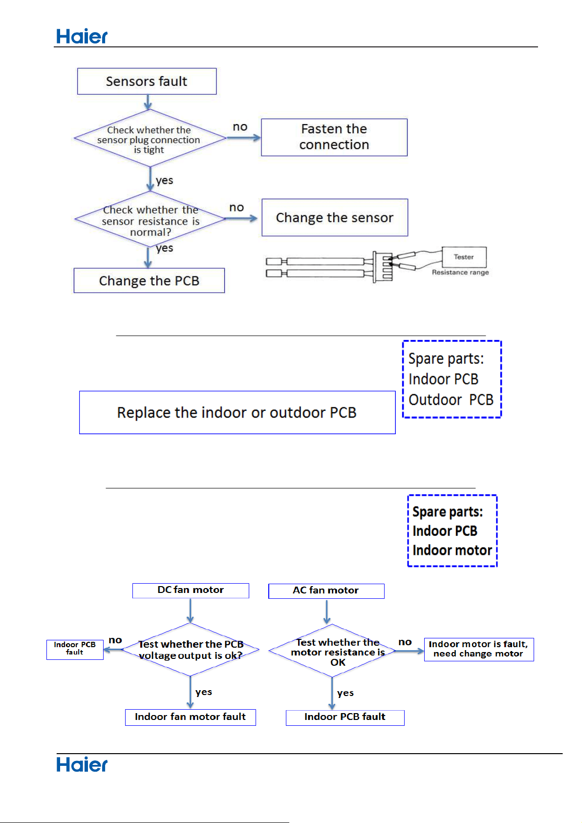
Seivice diagnosis
Domestic air conditioner
33
10.3.2 EEPROM abnormal
Indoor Display E4: indoor EEPROM error
Outdoor display F12: Outdoor EEPROM error; Outdoor LED1 flash 1 times
10101010101010
10.3.3 10101010101010
Indoor AC fan motor malfunction
Indoor display E14
This is caused by indoor motor or indoor PCB fault
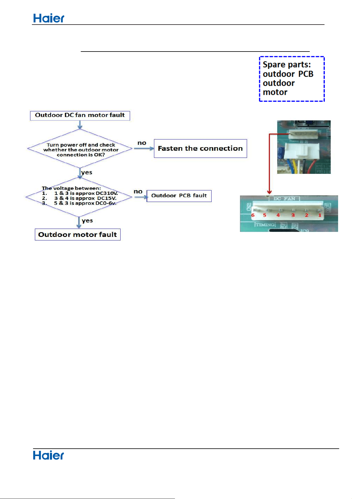
10.3.4 Outdoor DC fan motor fault
Outdoor display F8 LED1 flash 9 times
Seivice diagnosis
Domestic air conditioner
34
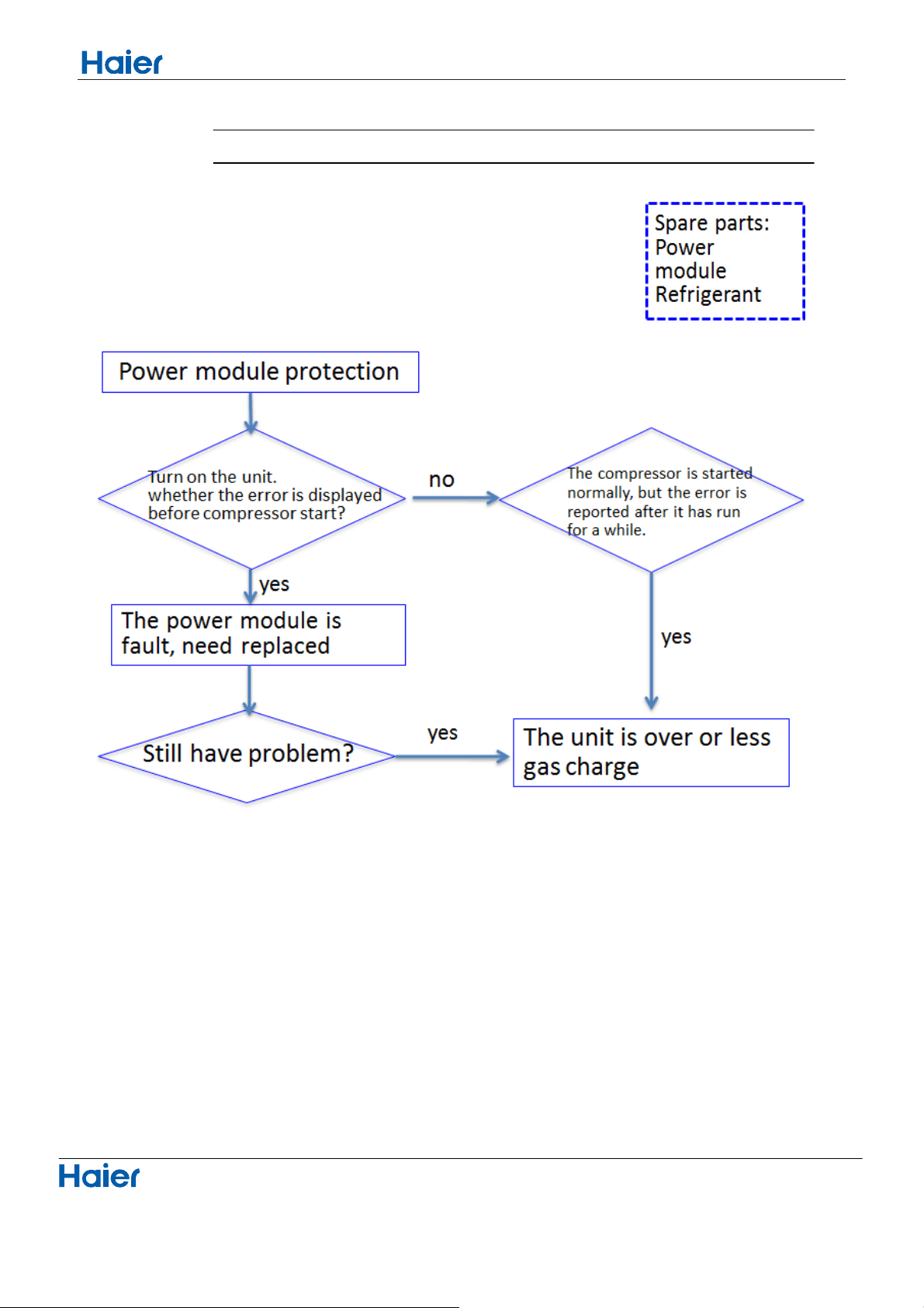
10.3.5 IPM protection
Outdoor display
Seivice diagnosis
Domestic air conditioner
35
Under this error, please ensure the refrigerating system pressure is normal, and no block, then replace power module
F1 LED1 flash 2 times; F22 LED1 flash 3 times
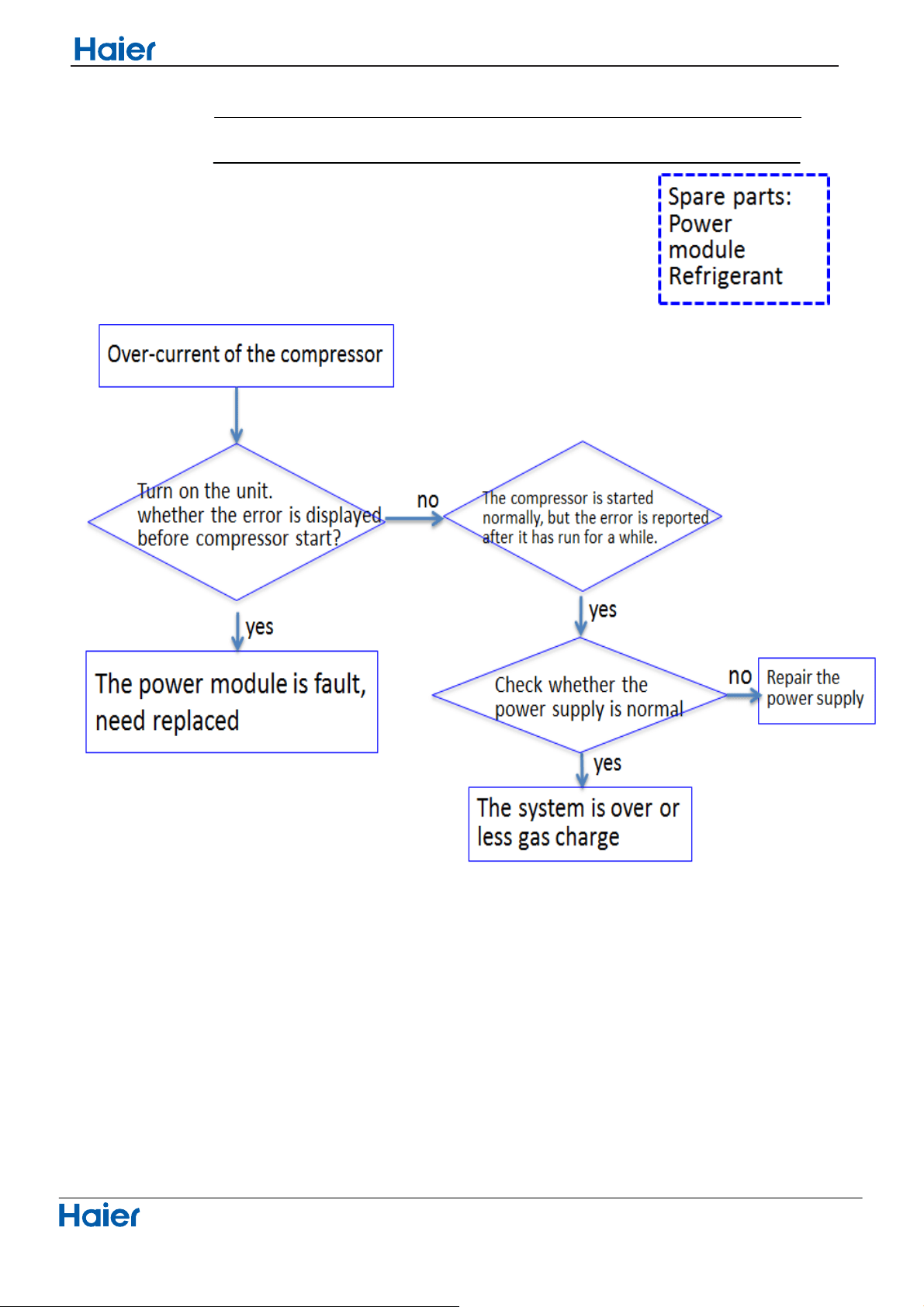
10.3.6 Over-current of the compressor
Outdoor Display
Domestic air conditioner
36
Seivice diagnosis
F2, F23 LED1 flash 24 or 25 times
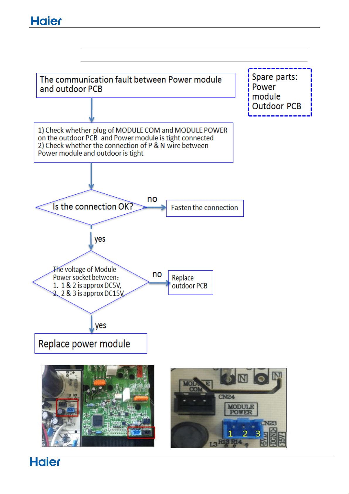
10.3.7 The communication fault between IPM and outdoor PCB
Outdoor display:
Seivice diagnosis
Domestic air conditioner
37
F3 LED1 flash 4 times
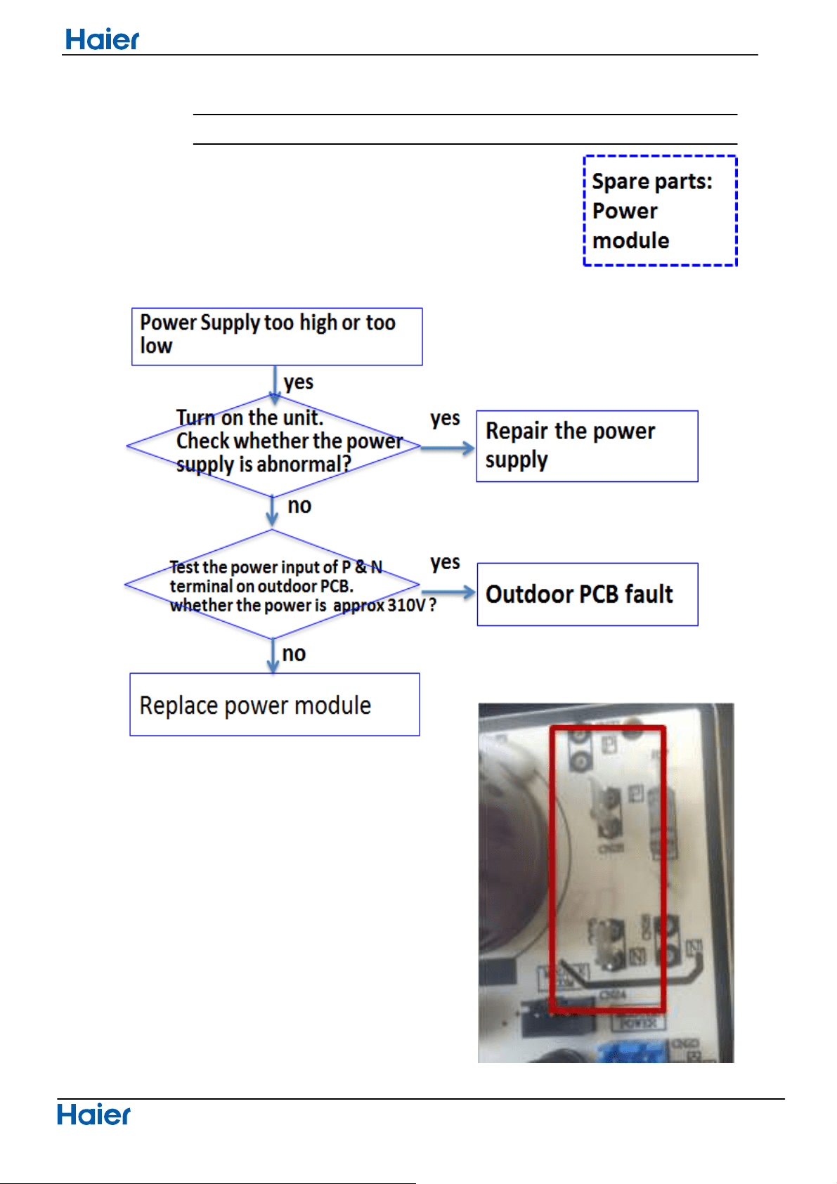
10.3.8 Power Supply Over or under voltage fault
Outdoor display:
Domestic air conditioner
38
Seivice diagnosis
F19 LED1 flash 6 times

10.3.9 Overheat Protection For Discharge Temperature
Outdoor display:
Seivice diagnosis
Domestic air conditioner
39
F4 LED1 flash 8 times
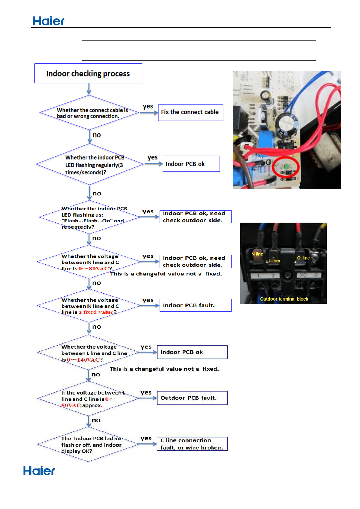
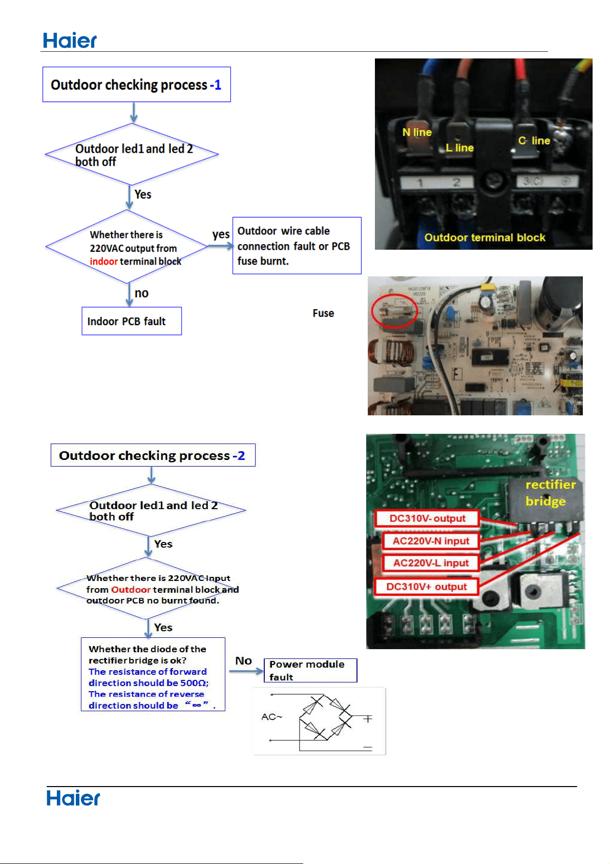
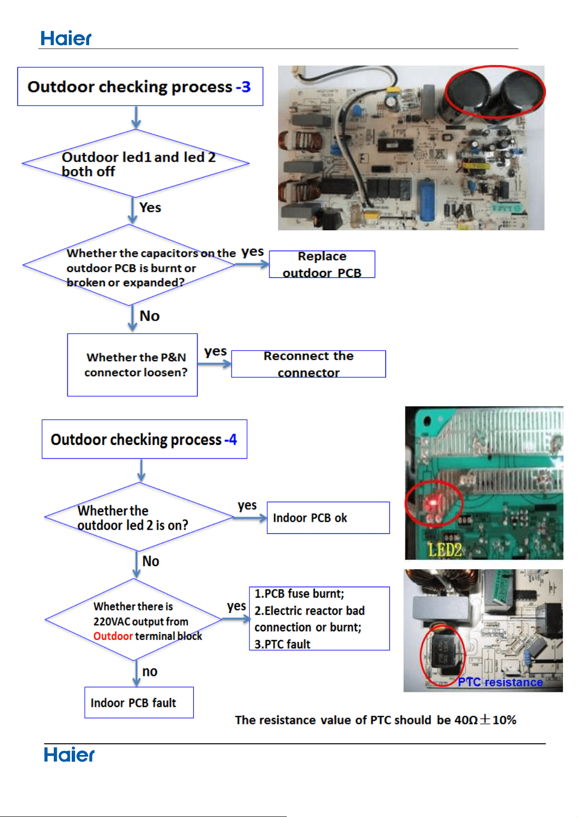
10.3.10 The communication fault between indoor and outdoor
Indoor display
E7
Outdoor display
LED1 flash 15 times
Domestic air conditioner
40
Seivice diagnosis
Seivice diagnosis
Domestic air conditioner
41
Seivice diagnosis
Domestic air conditioner
42

Seivice diagnosis
Domestic air conditioner
43
Seivice diagnosis
Domestic air conditioner
44
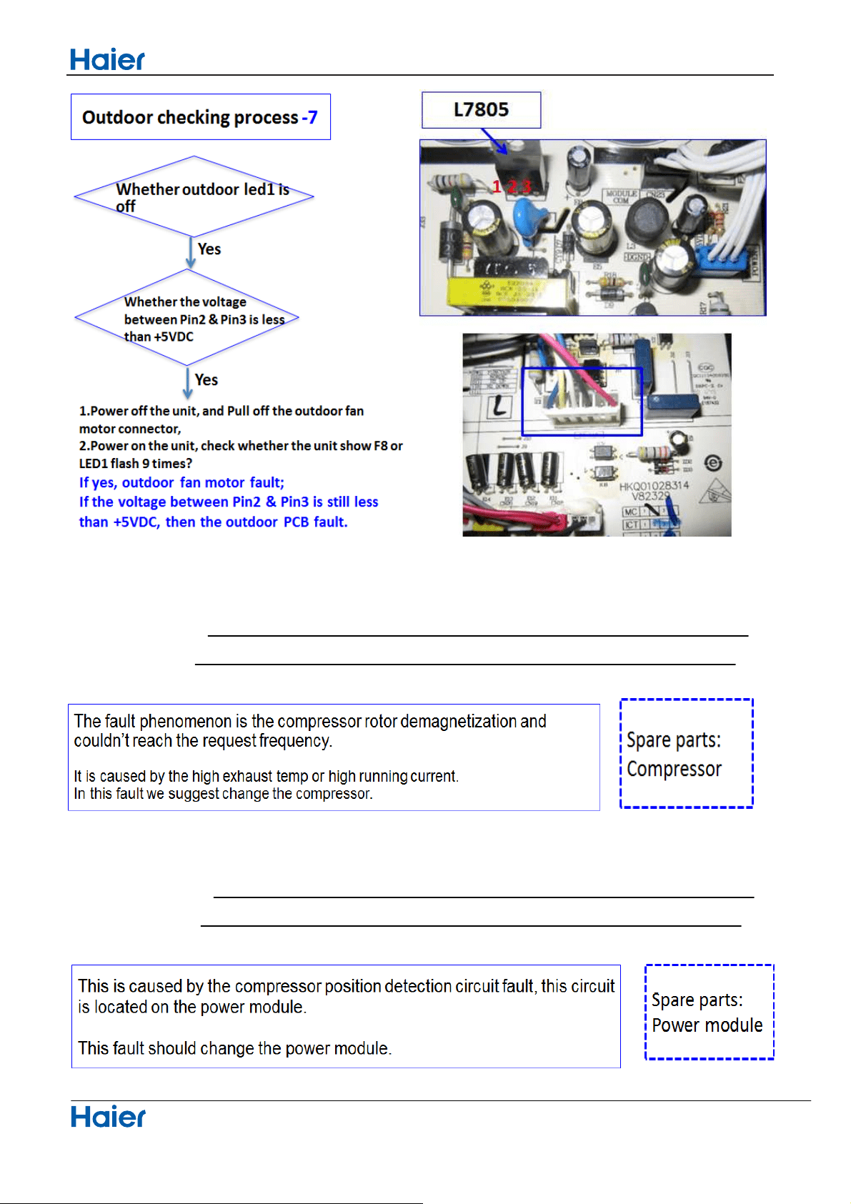
10.3.11
Outdoor Display
F11 LED1 flash 18 times
10.3.12
Outdoor Display
F28 LED1 flash 19 times
Compressor loss of synchronism detection
Compressor position detection circuit fault
Performance and curves diagrams
Domestic air conditioner
11.Performence and curves diagrams
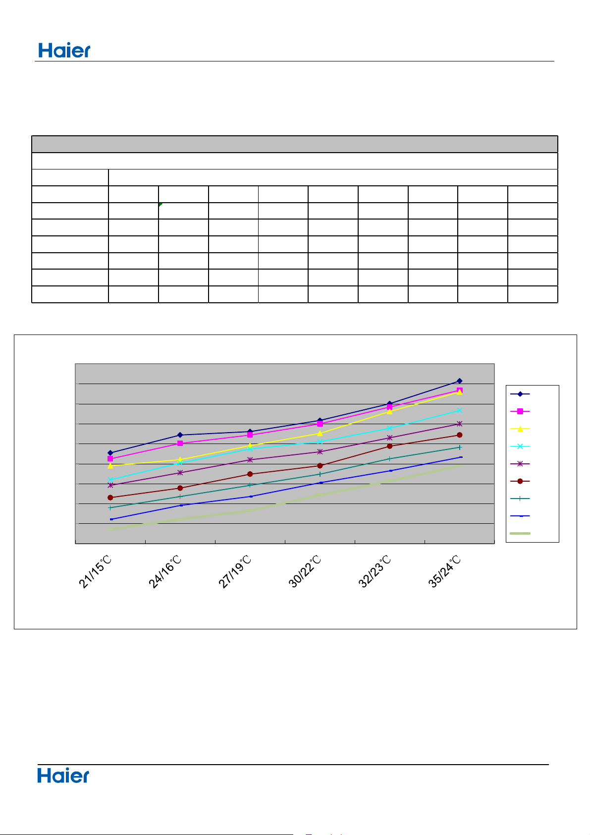
11.1 Cooling capacity-temperature curves
45
indoor temp.
DB/WB 10℃ 15℃ 20℃ 25℃ 30℃ 35℃ 38℃ 40℃ 43℃
21/15℃
6272 6124.8 5950 5600 5460 5152 4900 4606 4360
24/16℃
6720 6510 6104 6020 5776.4 5390 5180 4956 4610
27/19℃
6804 6720 6454 6370 6098.4 5740 5460 5180 4830
30/22℃
7084 7000 6762 6552 6300 5950 5740 5524.4 5220
32/23℃
7504 7420 7308 6888 6650 6440 6126.4 5824 5570
35/24℃
8072 7840 7798 7336 7000 6720 6412 6160 5950
performance curves
cooling value-temerature table
outdoor temp
4000
4500
5000
5500
6000
6500
7000
7500
8000
8500
cooling capacity (W)
cooling capacity and indoor/outdoor temp.curves
10℃
15℃
20℃
25℃
30℃
35℃
38℃
40℃
43℃
Performance and curves diagrams
Domestic air conditioner
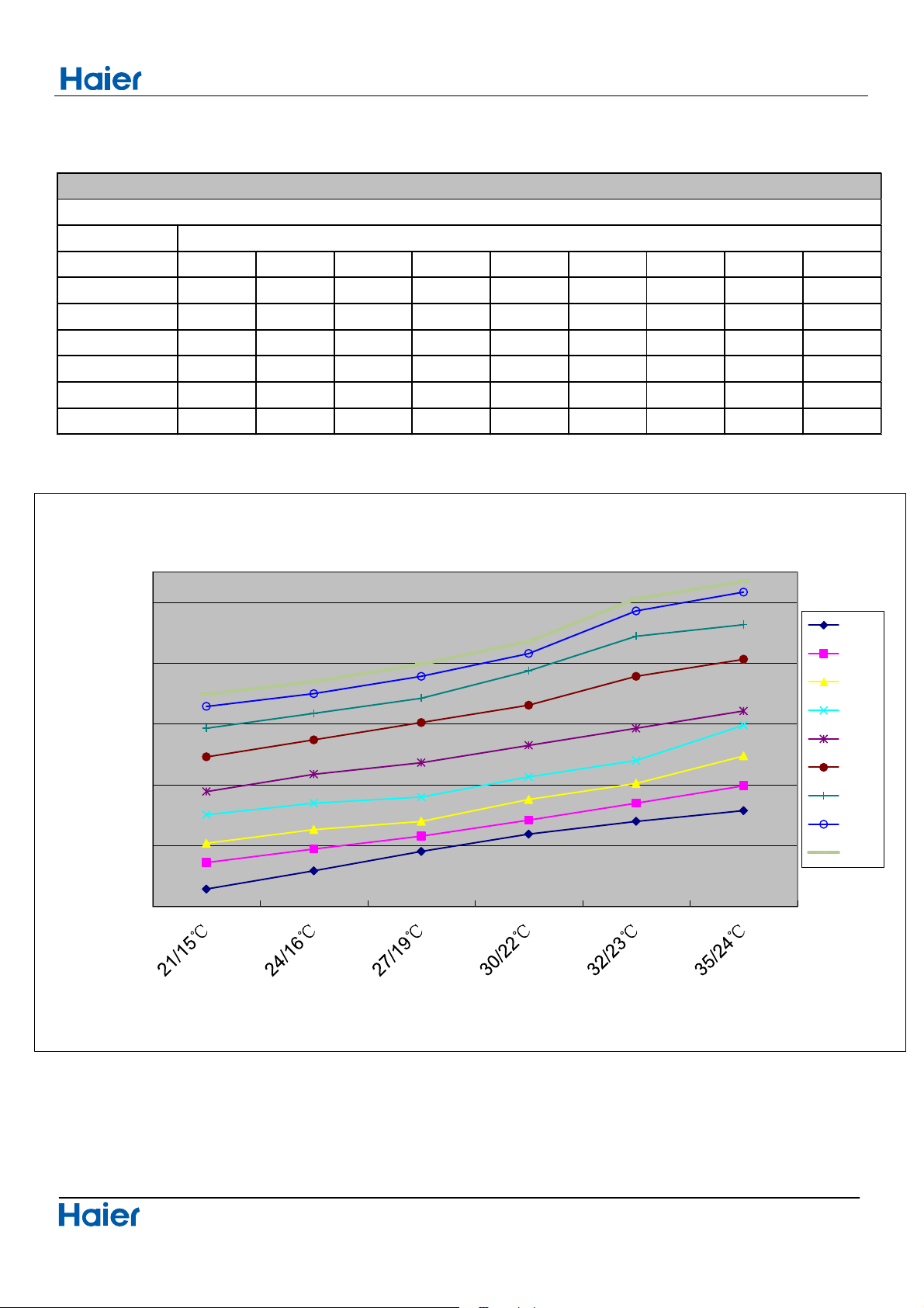
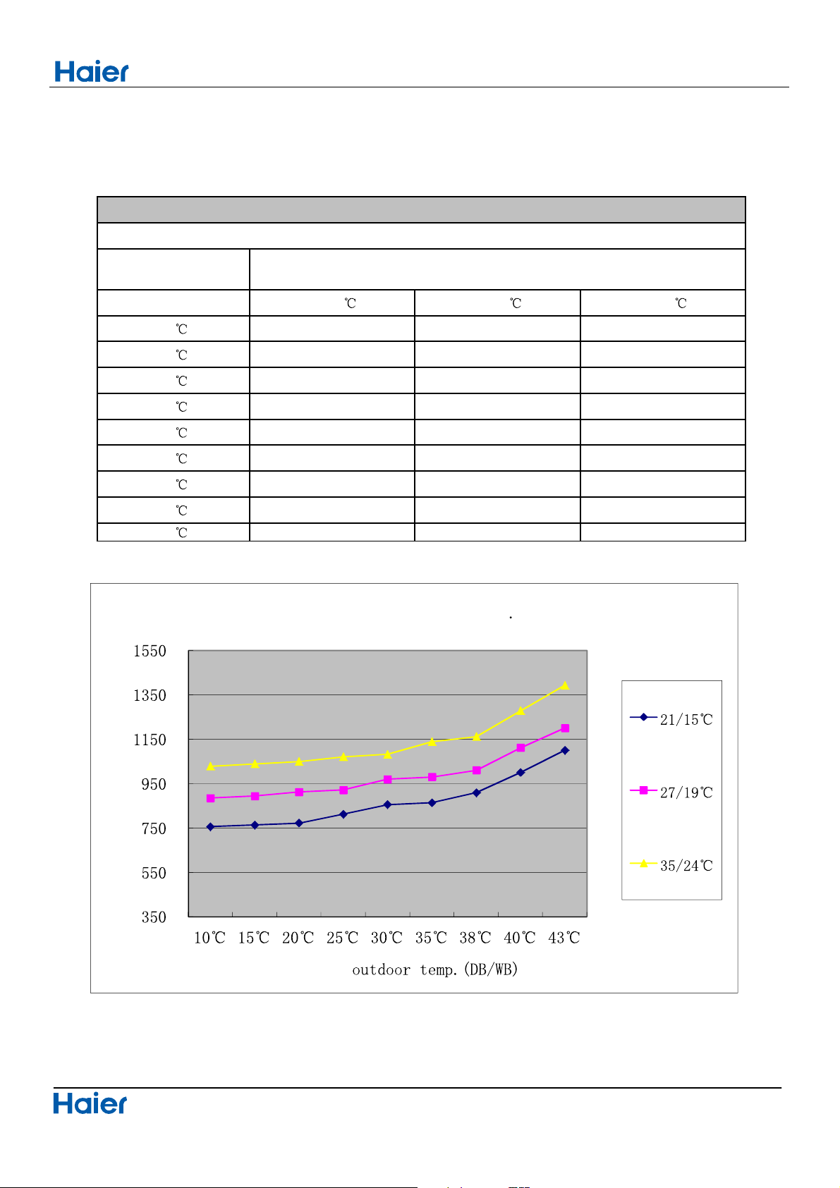
11.2 Cooling power consumption value- temperature curves
46
indoor temp.
DB/WB 10℃ 15℃ 20℃ 25℃ 30℃ 35℃ 38℃ 40℃ 43℃
21/15℃
1557 1644 1708 1802 1878 1992 2086 2158 2198
24/16℃
1617 1689 1753 1840 1935 2048 2135 2200 2240
27/19℃
1681 1731 1780 1860 1973 2105 2185 2257 2297
30/22℃
1738 1784 1852 1926 2030 2162 2275 2332 2372
32/23℃
1780 1840 1905 1980 2086 2257 2389 2472 2512
35/24℃
1815 1897 1995 2096 2143 2313 2427 2534 2570
performance curves
power consumption temp.table
outdoor temp.
1500
1700
1900
2100
2300
2500
power consumption(w)
indoor tempe.(DB/WB)
power consumption and temp.curves
10℃
15℃
20℃
25℃
30℃
35℃
38℃
40℃
43℃
Performance and curves diagrams
Domestic air conditioner
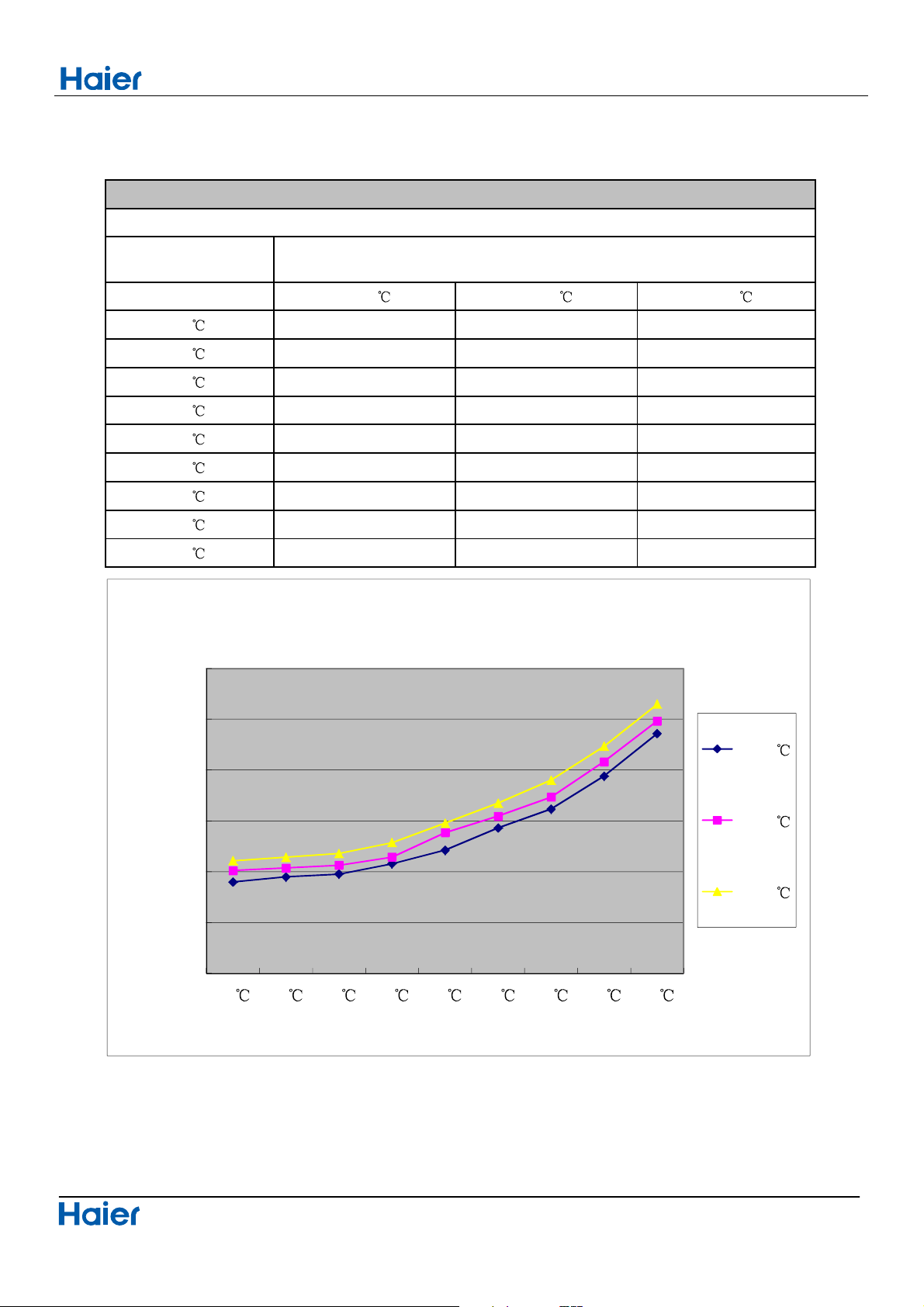
11.3 Cooling discharge pressure curves
47
outdoor temp.
(humidity 46%)
DB/WB
21/15
27/19 35/24
10
1899 2010 2107
15
1949 2037 2141
20
1976 2064 2178
25
2079 2144 2287
30
2211 2385 2478
35
2429 2546 2674
38
2615 2734 2901
40
2940 3082 3234
43
3359 3484 3650
performance curves
cooling discharge pressure.table
indoor temp.
1000
1500
2000
2500
3000
3500
4000
10
15 20 25 30 35 38 40 43
discharge pressure (Kpa)
outdoor temp.(DB/WB)
cooling discharge pressure and temp. curves
21/15
27/19
35/24
Performance and curves diagrams
Domestic air conditioner
11.4 Cooling suction pressure curves
48
outdoor temp.
(humidity 46%)
DB/WB
21/15
27/19 35/24
10
9201688757
15
0401598567
20
0501319277
25
2701229318
30
2801179658
35
9311189468
38
910 1011 1163
40
1001 1112 1279
43
1101 1201 1394
indoor temp.
performance curves
cooling suction pressure.table
suction pressure (Kpa)
cooling suction pressure and temp curves
Performance and curves diagrams
Domestic air conditioner
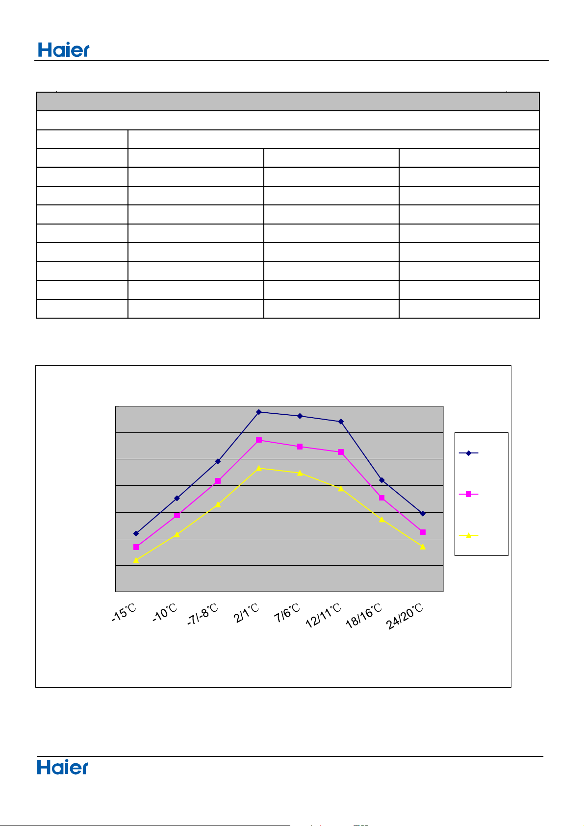
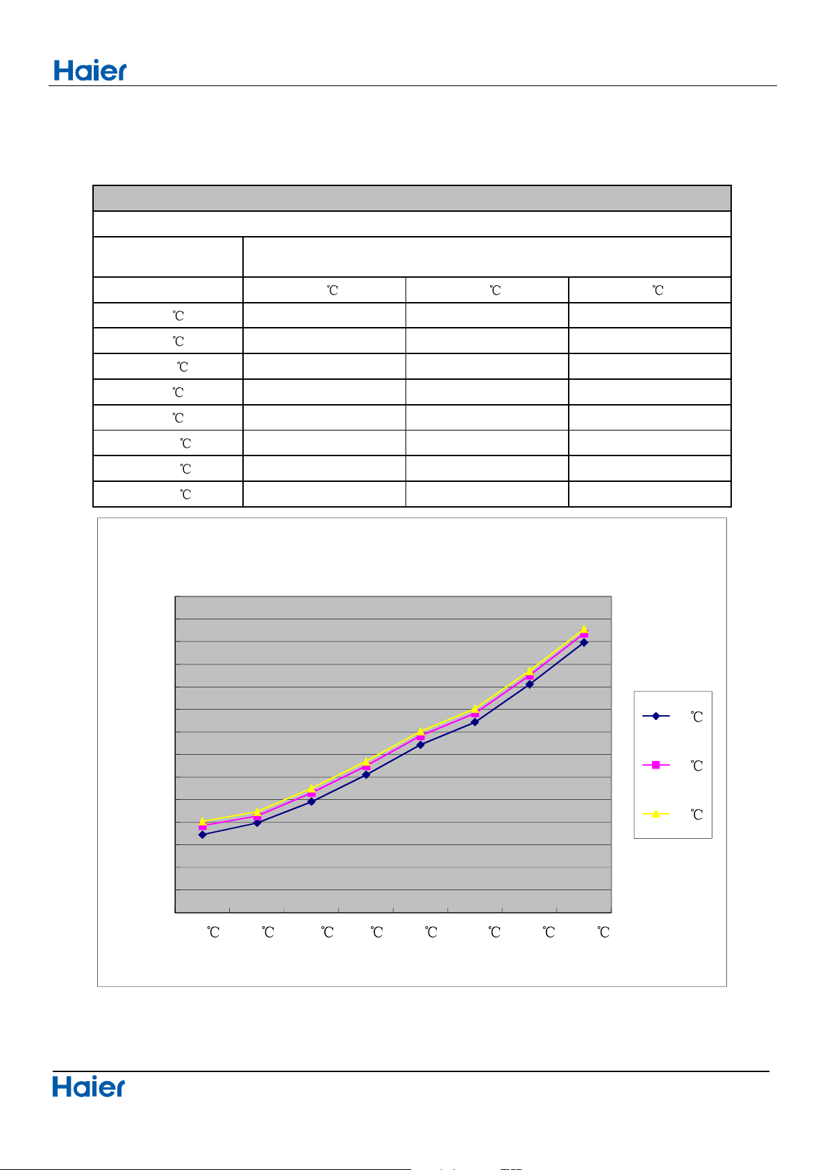
11.5 Heating capacity-temperature curves
49
outdoor temp.
DB/WB 10℃ 20℃ 27℃
-15℃
5194 4686 4190
-10℃
6526 5877 5158
-7/-8℃
7920 7181 6289
2/1℃
9780 8722 7663
7/6℃
9629 8477 7481
12/11℃
9417 8268 6892
18/16℃
7209 6537 5727
24/20℃
5941 5252 4698
performance curves
heating capacity and indoor/outdoor temp.table
indoor temp.(humidity 46%)
3000
4000
5000
6000
7000
8000
9000
10000
conoling capacity(w)
outdoor tempe.(DB/WB)
heating capacity and indoor/outdoor temp.curves
10°C
20°C
27°C
Performance and curves diagrams
Domestic air conditioner
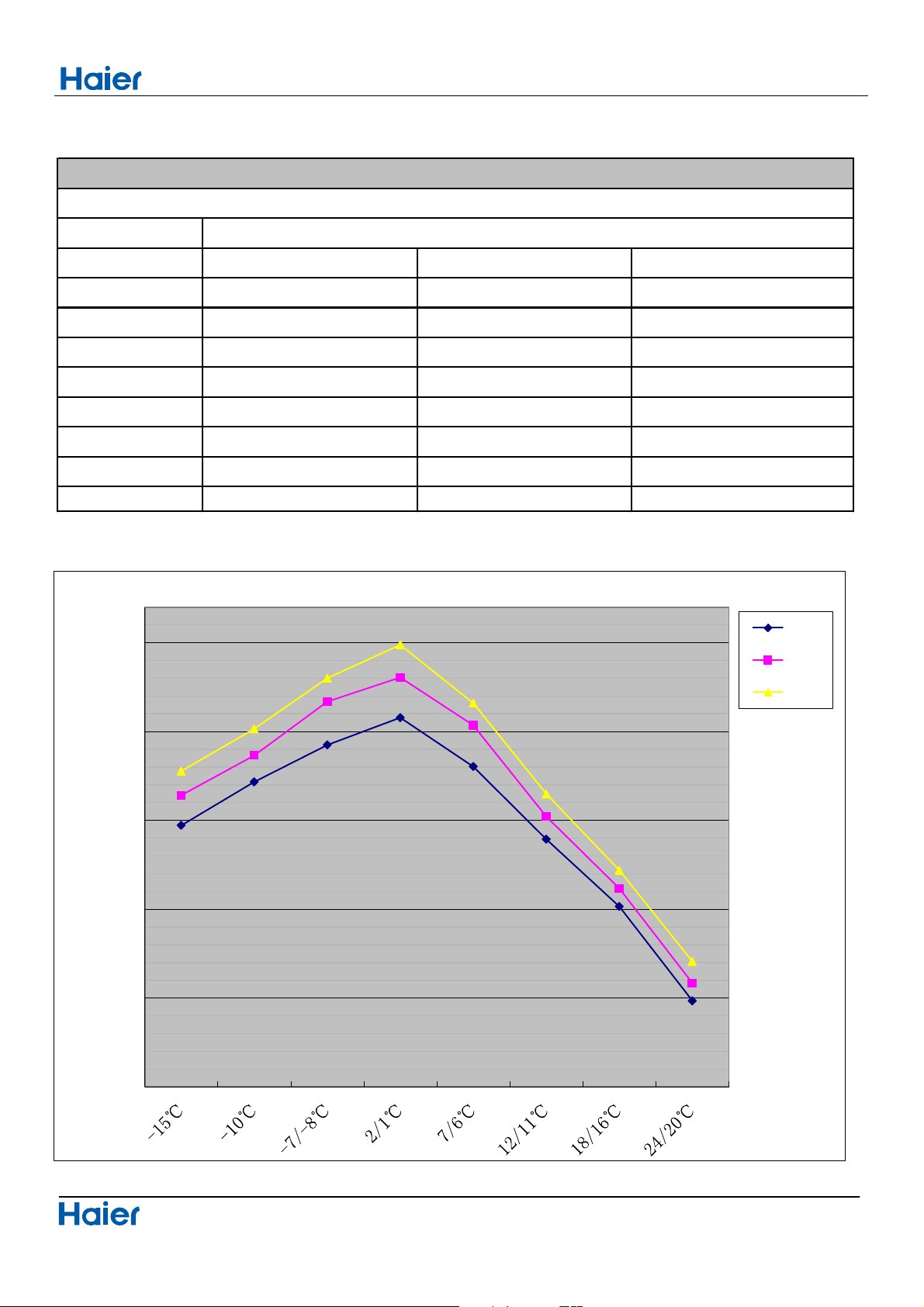
11.6 Heating power consumption value- temperature curves
50
outdoor temp.
DB/WB 10℃ 20℃ 27℃
-15℃
1972 2141 2277
-10℃
2216 2366 2515
-7/-8℃
2424 2669 2800
2/1℃
2578 2804 2988
7/6℃
2303 2535 2660
12/11℃
1894 2021 2149
18/16℃
1515 1617 1719
24/20
℃
985 1084 1205
performance curves
power consumption value-temp.table
indoor temp.(humidity 46%)
500
1000
1500
2000
2500
3000
consumption(w
10℃
20℃
27℃
Performance and curves diagrams
Domestic air conditioner
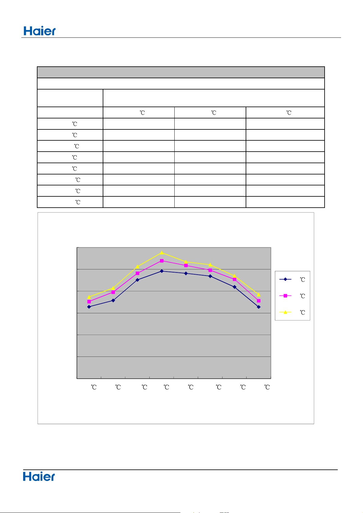
11.7 Heating discharge pressure curves
51
outdoor temp
DB/WB
10
20 27
-15
768246724462
-10
370308929872
-7/-8
365311439523
2/1
388389631643
7/6
276309539043
12/11
606328436433
18/16
153337238903
24/20
329228728362
performance curves
heating discharge pressure.table
indoor temp.
1000
1500
2000
2500
3000
3500
4000
-15
-10 -7/-8 2/1 7/6 12/11 18/16 24/20
discharge pressure (Kpa)
outdoor temp.(DB/WB)
heating discharge pressure and temp. curves
10
20
27
Performance and curves diagrams
Domestic air conditioner
11.8 Heating suction pressure curves
52
outdoor temp
DB/WB
10
20 27
-15
504583543
-10
744824893
-7/-8
155235294
2/1
076156116
7/6
308487447
12/11
409488448
18/16
1011 1051 1071
24/20
1197 1237 1257
performance curves
heating suction pressure.table
indoor temp.
0
100
200
300
400
500
600
700
800
900
1000
1100
1200
1300
1400
-15
-10 -7/-8 2/1 7/6 12/11 18/16 24/20
suction pressure (Kpa)
outdoor temp.(DB/WB)
heating suction pressure and temp. curves
10
20
27
Circuit diagrams
Domestic air conditioner
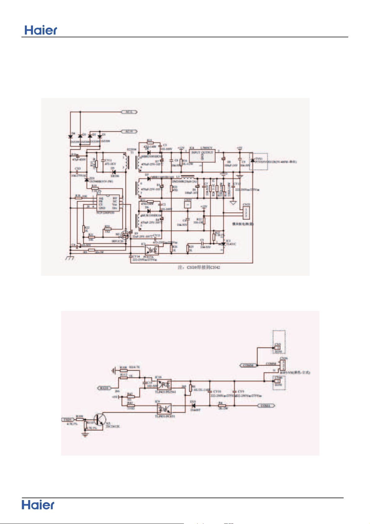
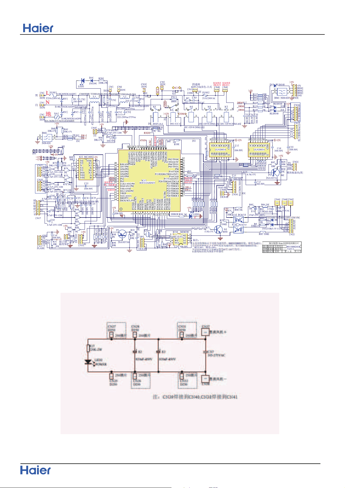
12 Circuit diagrams
12.1 Outdoor unit control board Circuit Diagrams
53
Circuit diagrams
Domestic air conditioner
54
Circuit diagrams
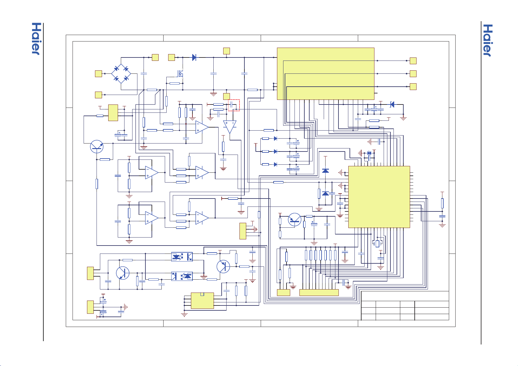
Domestic air conditioner
12.2 Module board Circuit Diagram
55
1
1
2
2
3
3
4
4
D D
C C
B B
A A
C009
103
IG8
40A@100
℃
1
2
3
4
BG1
D25XB60
C404
CBB21-474/630V
C405
CBB21-474/630V
RS1
0.01/5W
R215
10K
RS2
0.01
R003
100
R002 10K
R007 10K
R006
100
4
5
6
U
V
W
C007104
C013
104
C005
104
C201
104
R220
33
R219 1K
R218
82
R217 1K
R009 10K
R005
10K
R032
4.7K
R008 10K
C202
104
C207
104
C208
104
R221
140
R216
10
R224
4.7K
R211
1K
R212
9.1K
R209
1K
R210
10K
R214
47
R207
1K
5V
4
8
5
6
7
R015
330
R208
10K
R014
330
R013
330
R018
4.7K
R016
1K
R012
4.7K
R011
4.7K
R004 10K
R019
4.7K
R213 100
1
2
3
4
5
6
7
8
R206
1K
R205
1K
R203
1K
R204
6.2K
R201
1K
R202
6.2K
1
2
3
4
5
6
7
8
5V
5V
1
2
3
CN11
B3B-XH
TR2
MMBT9012/2SA1037AK
TR3
MMBT9013
C018
103
C016
472
C017
223
C014
102
C032
224
C036
224
C023
224
C015
102
C034
224
C001
104
5V
E413
100U/25V
E412
47U/25V
E411
47U/25V
E410
47U/25V
5V
5V
C019
103
C020
102
5V
C205
223
C003
104
C002
104
C006
104
5V
R231
10K
R228
470K/1W/1%
R229
5.1K/1%
D205
RLS4148
D204
RLS4148
5V
1
2
3
CN10
B3B-XH
15V
5V
E501
100U/25V
C011
104
E502
100U/25V
C012
104
D206
24V/1W
15V
R017
10K
C406
CBB21-474/630V
E504
100U/25V
R222
390Ω
R225
4.7K
C204
104
C028
103
1
23
5V
R222,R225参数由压缩机退磁电流计算而定
1
1
2
3
4
5
6
7
8
9
10
11
12
13
14
15
16
17
18
19
20
21
22
23
24
25
26
27
28
29
30
31
32
33
34
35
36
37
38
39
40
41
42
43
44
45
46
47
48
49
50
51
52
53
54
55
56
57
58
59
60
61
62
63
64
IC1
R5F562T7DDFK
5V
R020 10K
R021 10K
R010
4.7K
R025 10K
5V
5V
1
2
3
JP2
5V
R001
10K
TR4
MMBT9012/2SA1037AK
R027
10K
R028
2K
R026
2K
P
N
VUFB
VP
UN
VVFB
VWFB
WP
UP
VP1
VN1
WN
VNC
VN
FO
CIN
VNC
VNO
U
V
W
2
3
4
5
6
7
8
9
10
11
12
13
14
15
16
17
18
19
20
21
22
23
24
25
IPM1
PS21997-AST
IC5A
HA17393BF
IC5B
HA17393BF
IC6A
HA1630D06
IC6B
HA1630D06
IC4A
HA1630D06
IC4B
HA1630D06
XT1
10M
D207
FFAF30U60DN
1
CN1
AC-L
1
CN2
AC-N
1
CN3
LI
1
CN4
LO
1
CN8
P
1
CN9
N
1
CN5
U
1
CN6
V
1
CN7
W
4
3
1
2
PC1
PC817A
4
3
1
2
PC2
PC817A
GND
4
GND
3
GND
2
GND
1
VCC
8
GND
7
SCL
6
SDA
5
IC3 AT24C04
海尔集团U-home本部科技有限公司
设计
审核
批准
专用号
版本号
页码
0011800377
V1
1 of 1
E001
10U/16V
1
2
3
4
5
6
7
8
9
10
11
JP1
5V
5V
TMS
TDI
TCK
TDO
TRST
RESET
MD0
MD1
EMLE
PLLVCC
WP
VP
UP
WN
VN
UN
eeprom_SDA
eeprom_SCL
IPM_FO
Is_converter
Vdc
RXD
TXD
PFC_c
OC_converter
OC_inverter
Is_inverter
1
2
3
4
CN38
EEPROM
5V
15V
2
3 5
6
8
IC7
TLP351/TLP251
TR1
MMBT9013
R223
330
5V
C038
103
预留
C008
104
C010
104
R033
510
RJ2
0
RJ1
0
R233
10
D203
US1M
R232
10
D202
US1M
R230
10
D201
US1M
15V
TVS1
C206
224
C203
104
U
V
W
+310
VUFB
VVFB
VWFB
FO-
CIN
GND-C
COM
VCC-C
IC1-17
IC1-18
IC1-19
IC1-26
IC1-27
IC1-28
IC1-29
IC1-30
IC1-31
IC1-32
IC1-40
IC1-41
IC1-43
IC1-45
IC1-48
IC1-61
IC1-62
IC1-63
IC1-64
IPM1-9
IPM1-25
Circuit diagrams
Domestic air conditioner
Sincere Forever
Haier Group
Haier Industrial Park, No.1, Haier Road
266101, Qingdao, China_
Http
//www.haier.com
Edited by :
Signed by :
Approved by:
Zhen Lingyun
He Shiquan
Zhang Jing
Zhang Xianqiang
Wall Mounted Type
ON/OFF-Series
SERIES:70 PLATFORM
This service information is designed for experienced repair technicians only and is not designed for use by the general public.
It does not contain warnings or cautions to advise non-technical individuals of potential dangers in attempting to service a product.
Products powered by electricity should be serviced or repaired only by experienced professional technicians. Any attempt to service or
Repair the product or products dealt with in this service information by anyone else could result in serious injury or death
WARNING
2014 (Qingdao Haier Air Conditioner General corp. , Ltd)
All rights reserved. Unauthorized copying and distribution is a violation of law
Haier Group
Version:V1 Date:2014-04-30
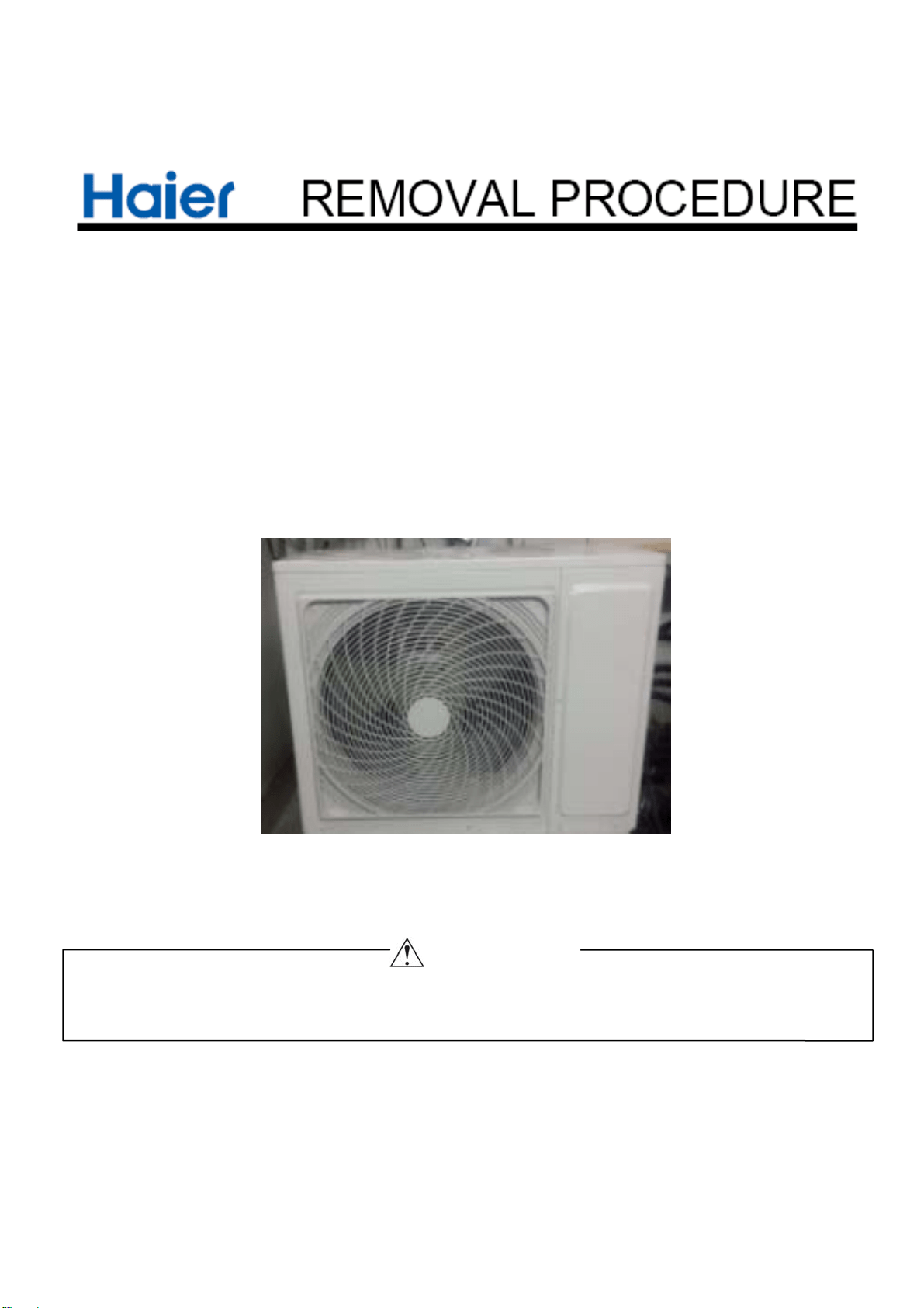
Removal of procedure
1Domestic air conditioner
1.Removal of Outdoor panel
Procedure Warning Be sure to wait 10 minutes or more after turning off all power supplies
before disassembling work
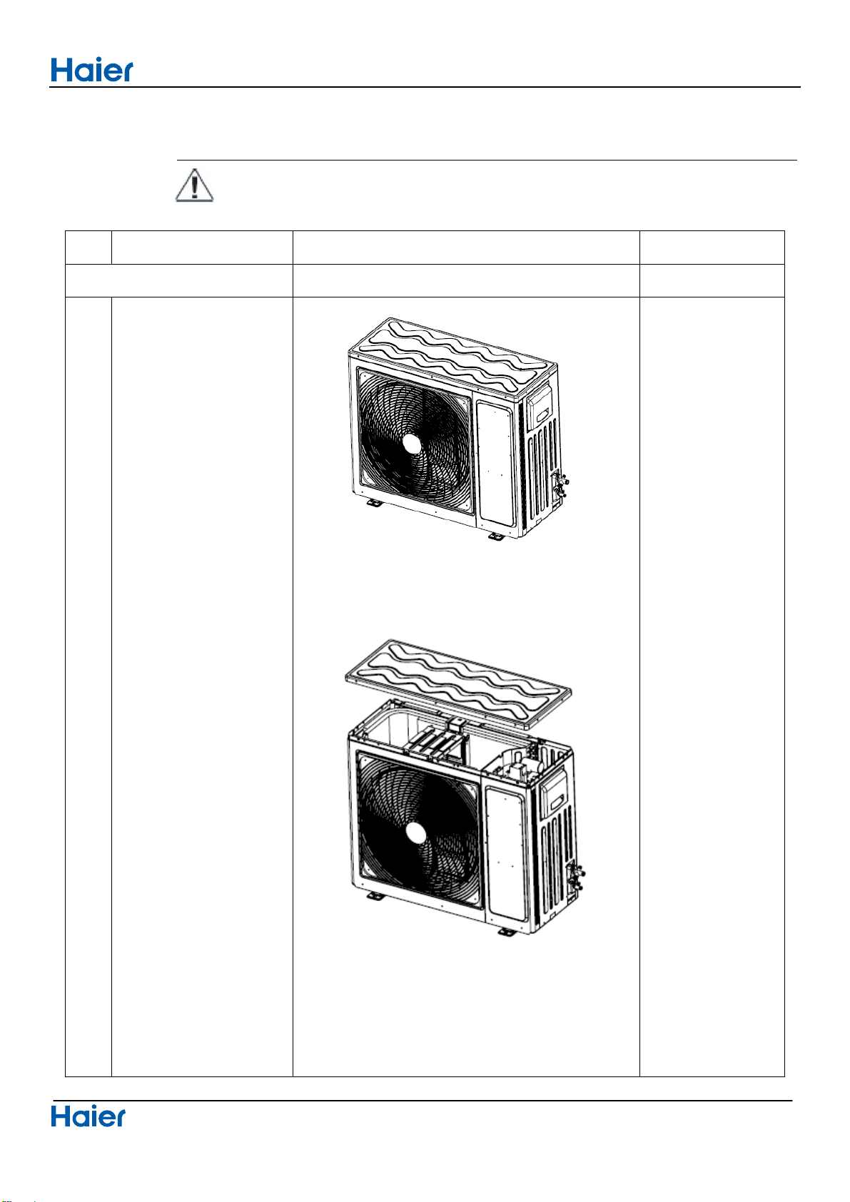
Step Procedure Points
1.Remove the panels
1
Loosen the 8 screws and
lift the top panel.
Removal of procedure
2Domestic air conditioner
Step Procedure Points
2
Loosen the screws of the
panel, pull and remove
the front panel.
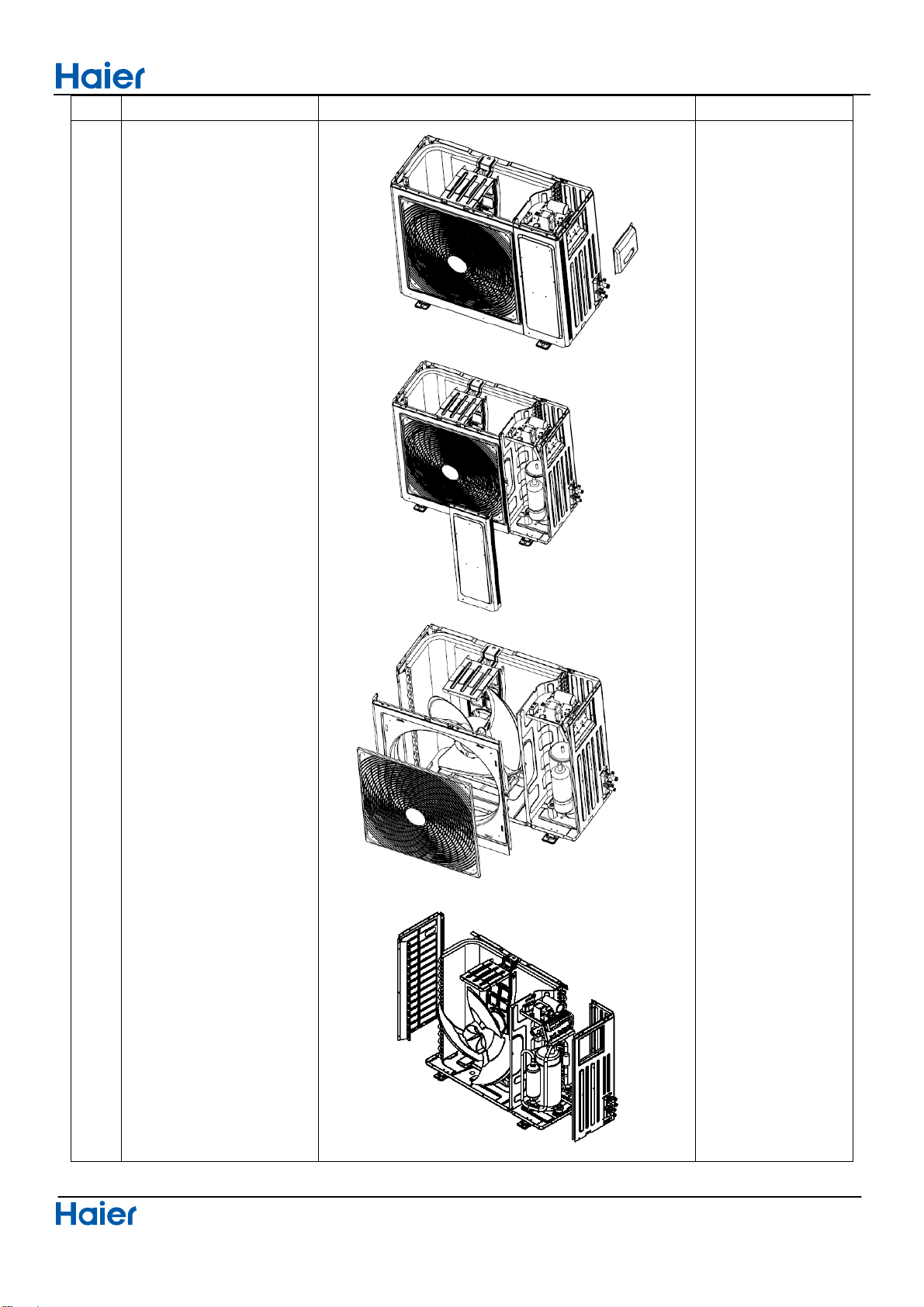
Removal of procedure
3Domestic air conditioner
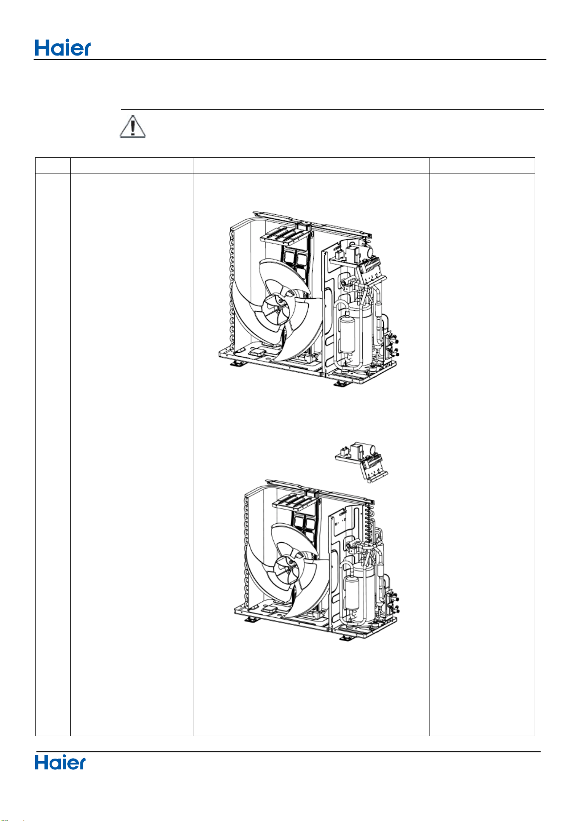
2.Removal of Electrical Box
Procedure Warning Be sure to wait 10 minutes or more after turning off all power supplies
before disassembling work
Step Procedure Points
1
Remove the fixing
screws, Than lift the
electrical box.
Removal of procedure
4Domestic air conditioner
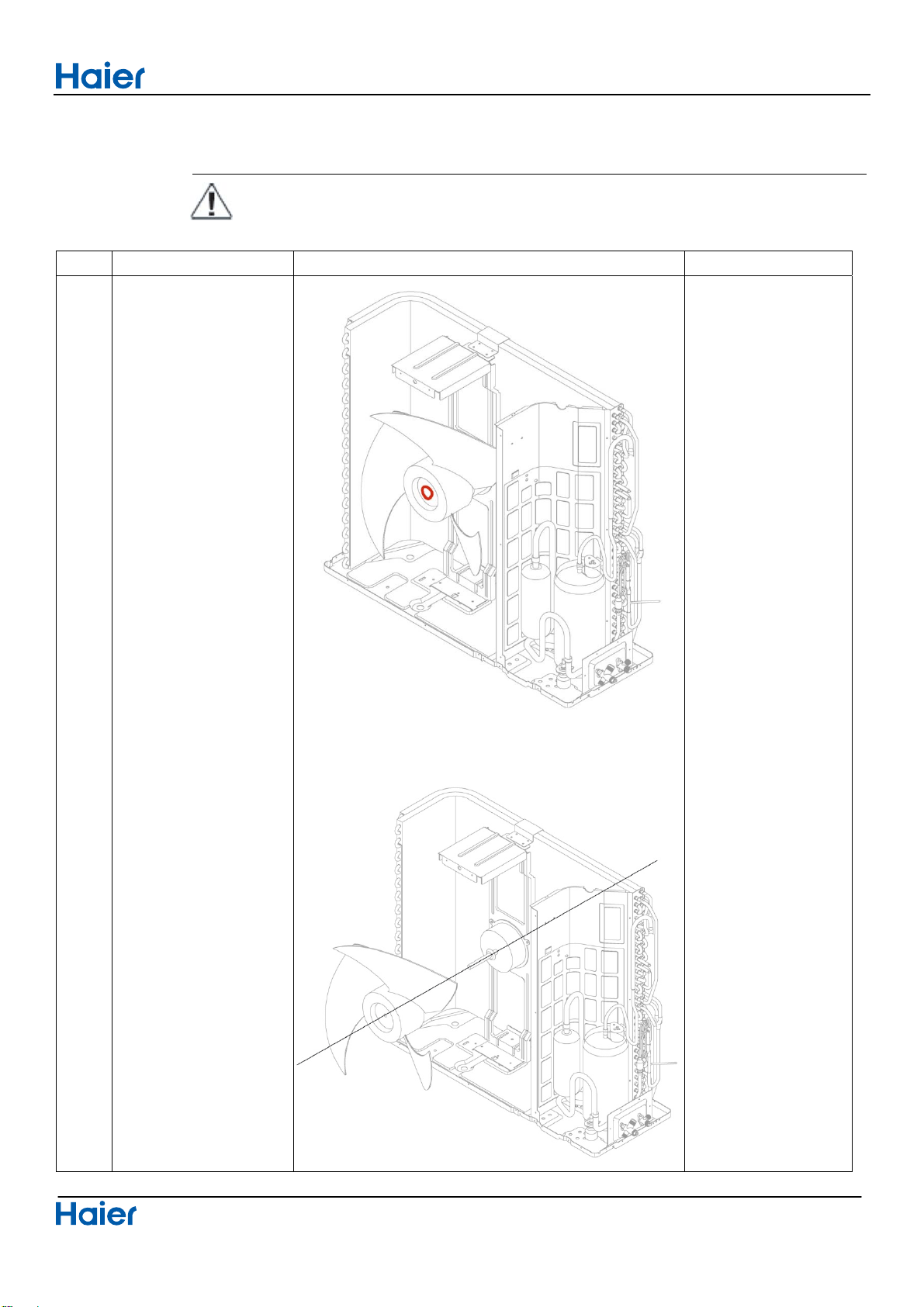
3.Removal of Fan and Fan Motor
Procedure Warning Be sure to wait 10 minutes or more after turning off all power supplies
before disassembling work
Step Procedure Points
1
Loosen the fixing
screw and remove the
fan.
Put the head wire
through the back of
the motor when
assembling.(so as
not to be entangled
with the propeller
fan)
Removal of procedure
5Domestic air conditioner
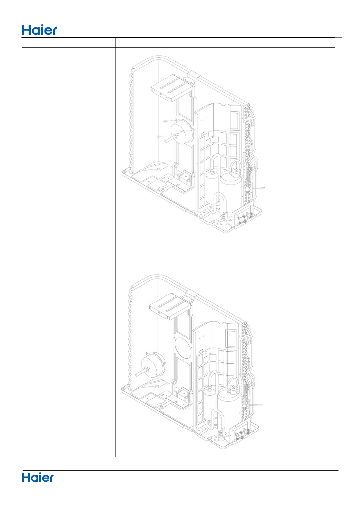
Step Procedure Points
2
Loosen the fixing
screws and remove
the fan motor.
Removal of procedure
6Domestic air conditioner
4.Removal of fan motor bracket and partition
Procedure Warning Be sure to wait 10 minutes or more after turning off all power supplies
before disassembling work
Step Procedure Points
1
Loosen the fixing
screws and remove
the fan motor bracket.
Removal of procedure
7Domestic air conditioner
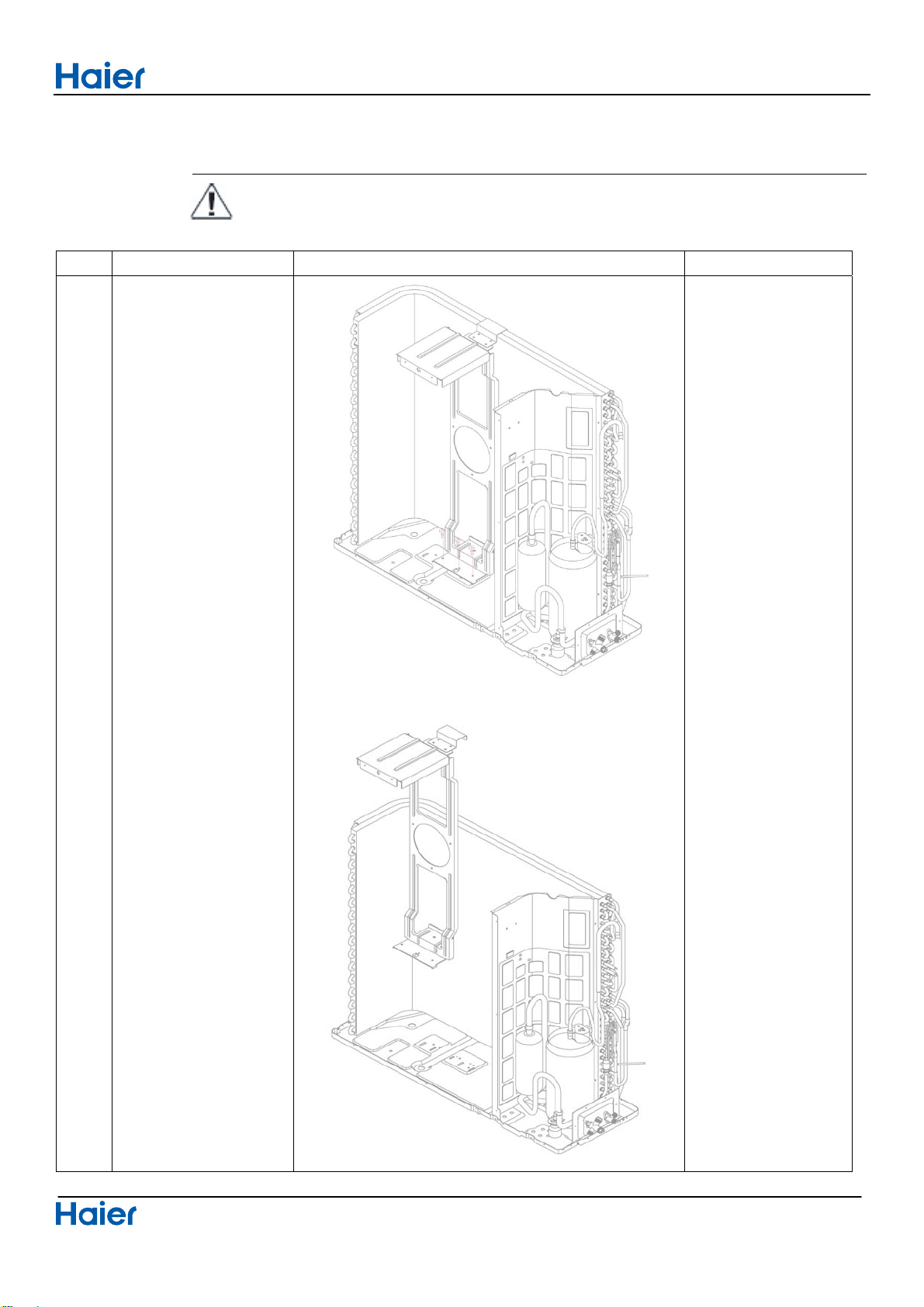
Step Procedure Points
2
Loosen the fixing
screws, the partition
plate has a hook on
the lower side, than lift
and pull the proof
plate.
When assembling, fit
the lower hook into
the bottom frame.
Removal of procedure
8Domestic air conditioner
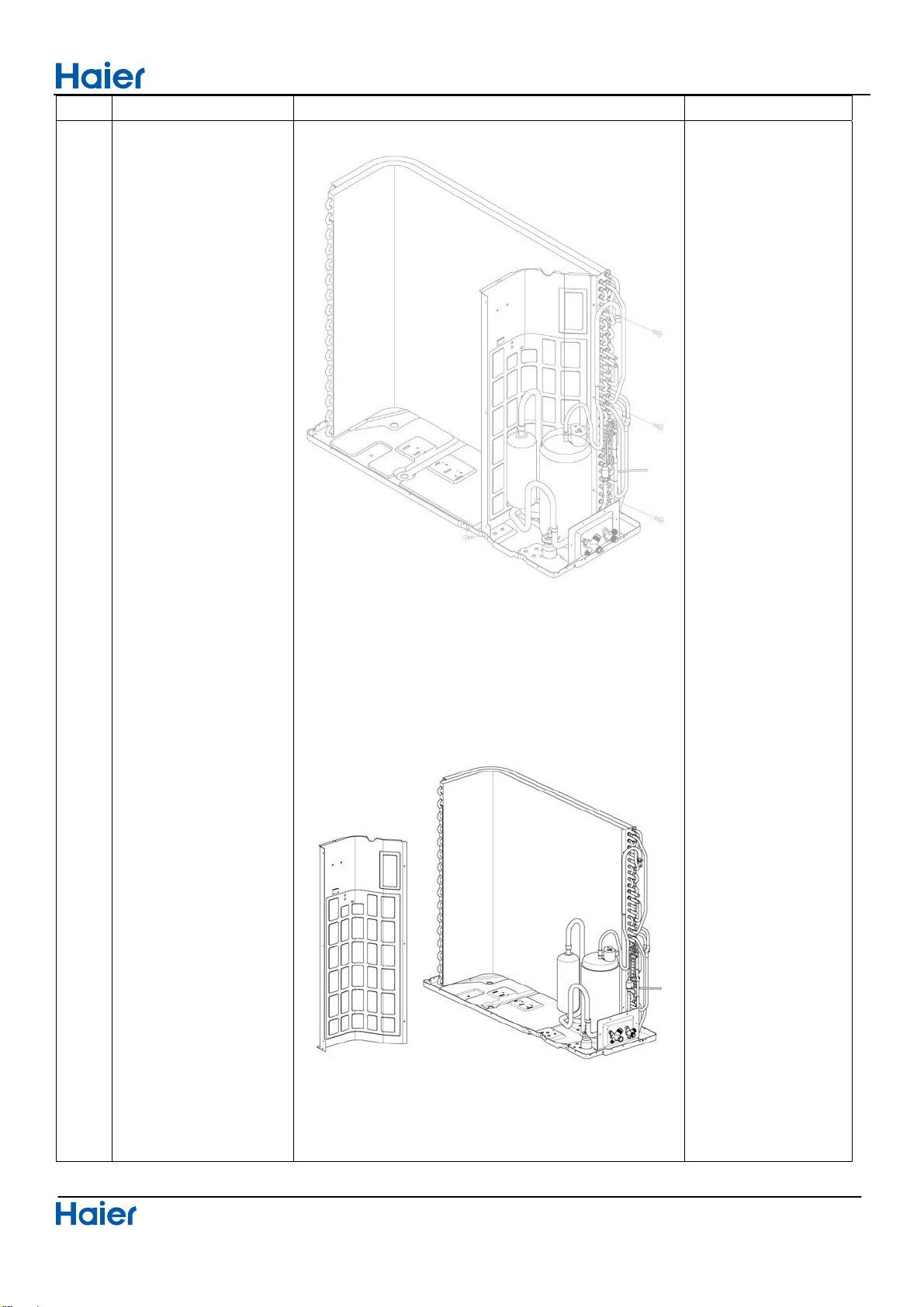
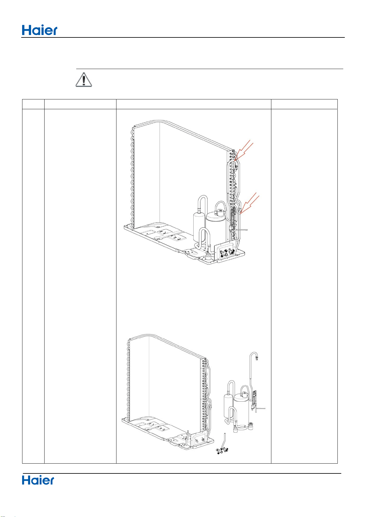
5.Removal of compressor and heat exchanger
Procedure Warning Be sure to wait 10 minutes or more after turning off all power supplies
before disassembling work
Step Procedure Points
1
Cut down the
concenting pipe and
put out the
compressor and
remove the valve
bracket.
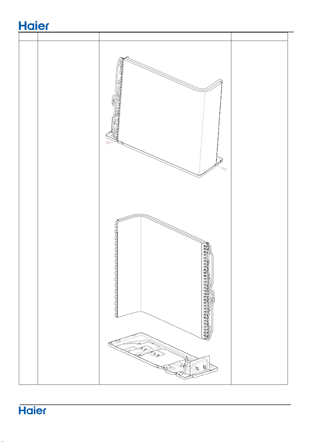
Removal of procedure
9Domestic air conditioner
Step Procedure Points
2
Loosen the marked
fixing screws and
remove the heat
exchanger.
WARNING:
·
If the supply cord is damaged, it must be replaced by the manufacturer,its service agent or
similarly qualified persons in order to avoid a hazard.
·
This appliance can be used by children aged 8 years and above and persons with reduced
physical, sensory or mentao capabilities or lack of experience and knowledge if they have
been given superivision or instruction concering use of the appliance in a safe way and
understand the hazards involved. Children shall
not play with the appliance. Cleaning and
·
The wiring method should be in line with the local wiring standard.
user maintenance shall not be made by children without supervision.
All the cables shall have got the European authentication certificate. During installation, when the
·
connecting cables break off, it must be assured that the grouding wire is the last one to be broken off.
The explosion-proof breaker of the air conditioner should be all-pole switch. Distance between its two
contacts should not be no less than 3mm. Such means for disconnection must be incorporated in the
·
·
Make sure installation is done according to local wiring regulation by professional persons.
·
·
A leakage explosion-proof breaker must be installed.
Make sure ground connection is correct and reliable.
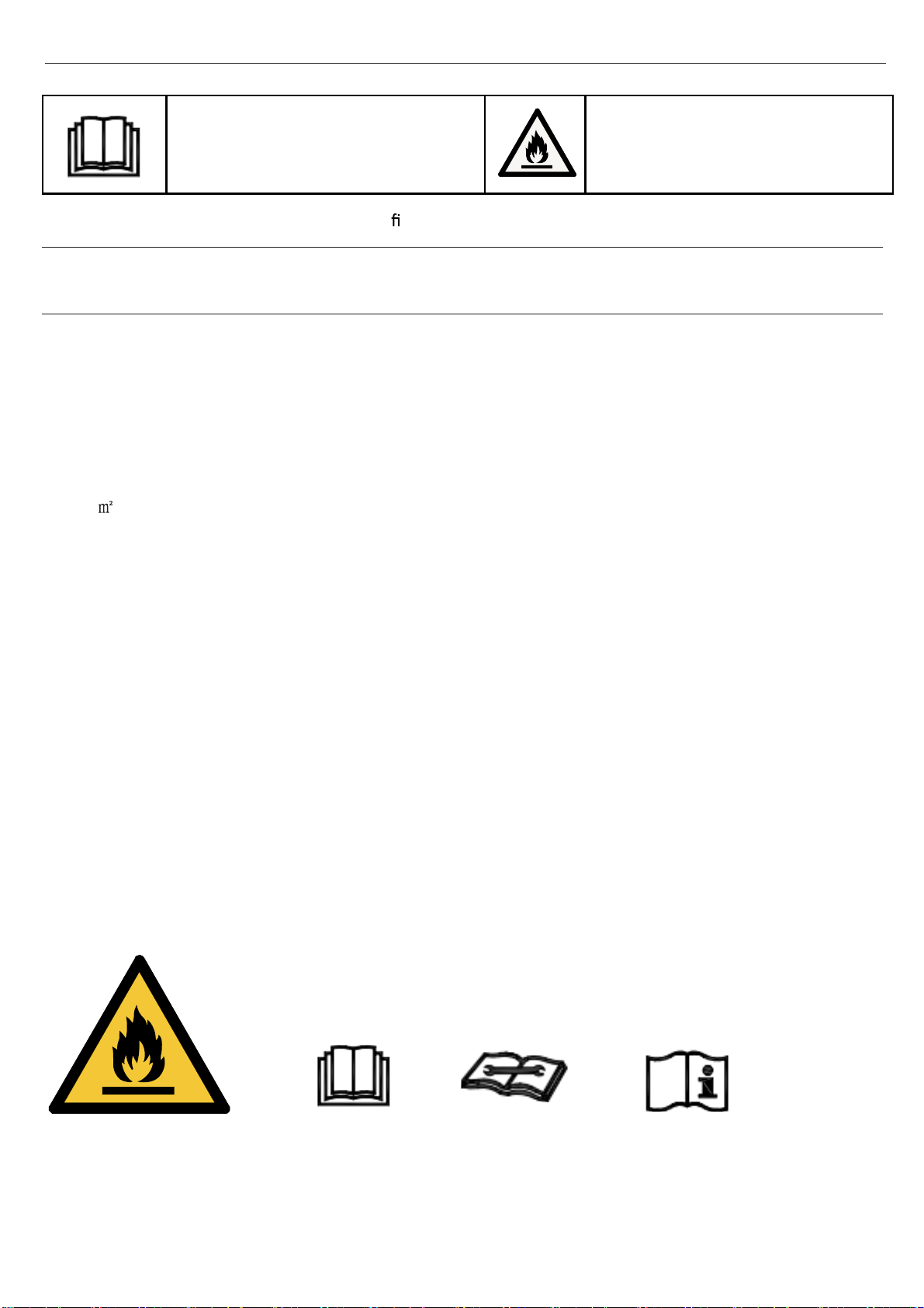
Read the precautions in this manual
carefully before operating the unit.
This appliance is filled with R32.
Do not use means to accelerate the defrosting process or to clean, other than those
recommended by the manufacturer.
·
Keep this manual where the user can easily nd it.
The appliance must be stored in a room without continuously operating ignition sources (for
example: open flames, an operating gas appliance or an operating electric heater).
Do not pierce or burn.
·
·
Be aware that refrigerants may not contain an odour.
·
The appliance must be installed, operated and stored in a room with a floor area larger than
3
.
·
·
Do not use a refrigerant other than the one indicated on the outdoor unit(R32) when installing,
moving or repairing. Using other refrigerants may cause trouble or damage to the unit, and
personal injury.
wiring.
No fire source around the
place of installation
Read operator’ manual
Read technical manual
Operator’ manual;operating instructions
F
A
C
E
D
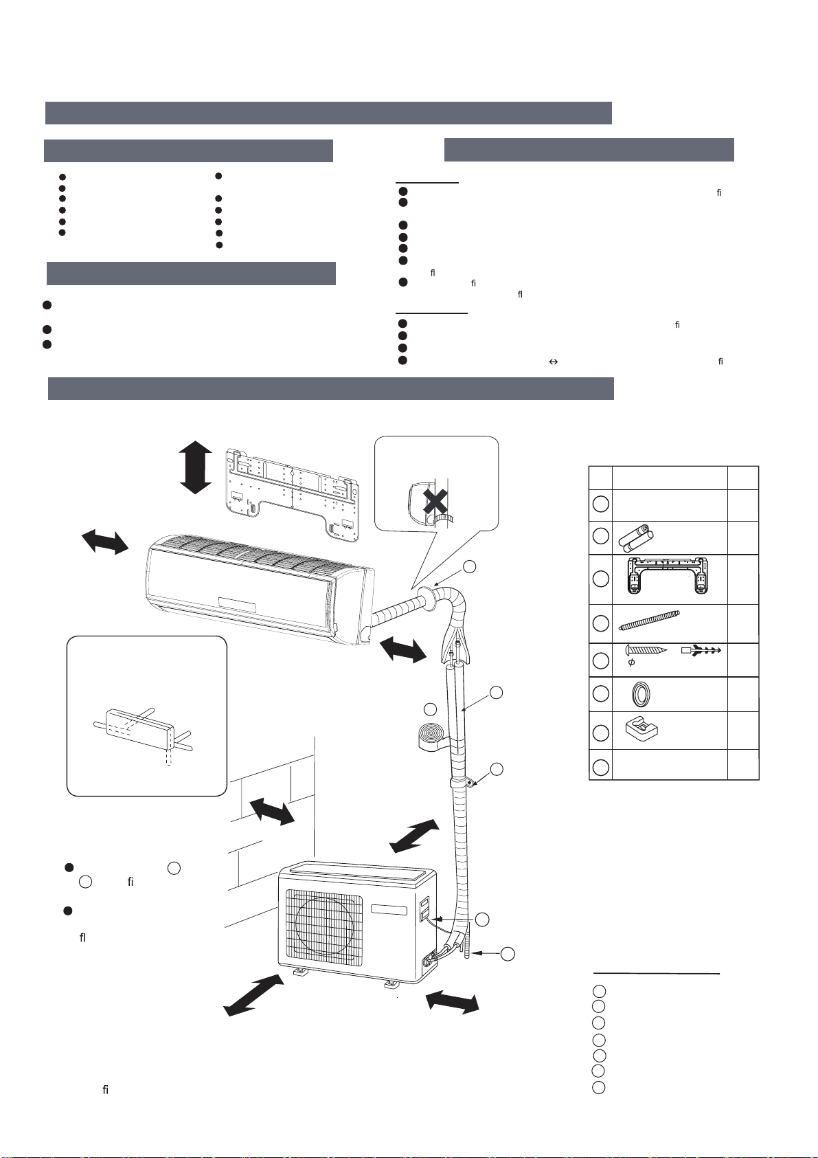
Drawing for the installation of indoor and outdoor units
Necessary parts for piping
Non-adhesive tape
Adhesive tape
Saddle (L.S) with screws
Connecting electric cable
for indoor and outdoor
Drain hose
Heating insulating material
Piping hole cover
The marks from to
in the
gure are the
parts numbers.
The distance between
the indoor unit and the
oor should be more
than 2m.
The models adopt HFC free refrigerant R32
more than
20cm
more than 20cm
more than 10cm
more than 30cm
more than
30cm
more than60cm
more than
60cm
A
G
Necessary Tools for Installation
Driver
Torque wrench
(17mm,22mm,26mm)
Nipper
Reamer
Hacksaw Pipe cutter
Gas leakage detector or
soap-and-water solution
Hole core drill
Flaring tool
Spanner(17,19 and 26mm) Knife
Measuring tape
Indoor Unit
Place, robust not causing vibration, where the body can be supported suf
ciently.
Place, not affected by heat or steam generated in the vicinity, where inlet and outlet of the
unit are not disturbed.
Place, possible to drain easily, where piping can be connected with the outdoor unit.
Place, where cold air can be spread in a room entirely.
Place, nearby a power receptacle, with enough space around. (Refer to drawings).
Place where the distance of more than lm from televisions, radios, wireless apparatuses
and
uorescent lamps can be left.
In the case of xing the remote controller on a wall, place where the indoor unit can
receive signals when the
uorescent
lamps in the room are lightened.
Outdoor Unit
Place, which is less affected by rain or direct sunlight and is suf ciently ventilated.
Place, possible to bear the unit, where vibration and noise are not increased.
Place, where discharged wind and noise do not cause a nuisance to the neighbors.
Place, where a distance marked is available as illustrated in the above gure.
Before inserting power plug into receptacle, check the voltage without fail.
The power
source is the same as the
corresponding name plate.
Install an exclusive branch circuit of the power.
A receptacle shall be set up in a distance where the power cable can be
reached.
Do not extend the cable by cutting it.
Selection of Installation Place
Power Source
A
F
C
E
D
G
B
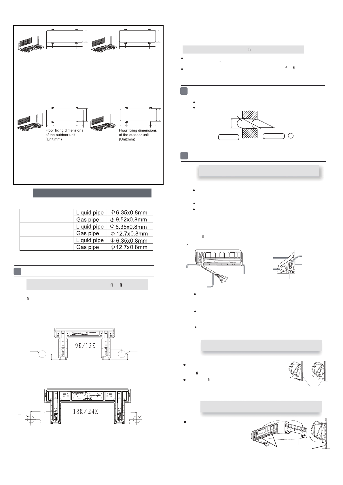
Arrangement of piping
directions
Rear left
Left
Rear
right
Right
Below
G
Preparation
Please be subject to the actual product purchased,the above picture is just for your reference.
Attention must be paid to
the rising up of drain hose
Read this manual before installation
Explain suf
ciently the operating means to the user according to this manual
Installation Manual of Room Air Conditioner
No. Accessory parts
Remote controller
R-03 dry battery
Mounting plate
Drain hose
Screw
Plastic cap
Cover
Cushion
1
1
2
3
4
5
6
7
8
2
1
1
4
1
4
1
Number
of
articles
Accessory parts
4X25
Connecting cable
Note:
1.Cooling only units don't have Drain-elbow
2.
Accessory parts may vary from each model,
please refer to the actual parts.
1
Indoor unit
Fix to side bar and lintel a mounting bar, Which is separately sold, and then
fasten the plate to the xed mounting bar.
Refer to the previous article, “ When the mounting plate is
position of wall hole.
Make a hole of 60 mm in diameter, slightly descending to outside the wall.
Install piping hole cover and seal it off with putty after installation
When the mounting plate is rst xed
1. Carry out, based on the neighboring pillars or lintels, a
to be
xed against the wall, then temporarily fasten the plate with one steel nail.
2. Make sure once more the proper level of the plate, by
hanging a thread with a
weight from the central top of the plate, then fasten securely the plate with the
attachment steel nail.
3. Find the wall hole location A using a measuring tape
When the mounting plate is xed side bar and lintel
Indoor side
Outdoor side
1
Fitting of the Mounting Plate and
Positioning of the wall Hole
Ø60mm
Wall hole
Thickness of wall
(Section of wall hole)
Piping hole pipe
Lid for right
piping
Lid for under piping pipe
Fix with adhesive tape
Lid for left piping
Heat insulation
material
Drain hose
Piping
Pipe supporting
plate
Indoor/outdoor electric cable
Indoor/outdoor electric cable and drain hose must be bound with refrigerant
piping by protecting tape.
[ Other direction piping ]
Cut away, with a nipper, the lid for piping according to the piping direction and
then bend the pipe according to theposition of wall hole. When bending, be
careful not to crash
pipes.
Connect beforehand the indoor/outdoor electric cable,
and then pull out the
connected to the heat insulation of connecting part specially.
proper leveling for the plate
rst xed “, for the
2
Making a Hole on the Wall and Fitting the Piping Hole Cover
G
Drawing of pipe
3
Installation of the Indoor Unit
[ Rear piping ]
Draw pipes and the drain hose, then fasten them with the adhesive tape
[ Left
·
Left-rear piping ]
In case of left side piping, cut away, with a nipper, the lid for left piping.
In case of left-rear piping, bend the pipes according to the piping direction to
the mark of hole for left-rear piping which is marked on heat insulation materials.
1. Insert the drain hose into the dent of heat insulation materials of indoor unit.
2. Insert the indoor/outdoor electric cable from backside of indoor
unit, and pull it
out on the front side, then connect them.
3. Coat the
aring seal face with refrigerant oil and connect pipes.
Cover the connection part with heat insulation materials closely, and make sure
xing with adhesive tape
Fixing the indoor unit body
Hang surely the unit body onto the upper notches of the
mounting plate. Move the body from side to side to verify its
secure
xing.
In order to
x the body onto the mounting plate,hold up
the body aslant from the underside and then put it down
perpendicularly.
mounting plate
When you unload the indoor unit,please use
then lift the bottom of the body outward
slightly and lift the unit aslant until it
leaves the mounting plate.
agraffe
mounting plate
Unloading of indoor unit body
your hand to arise the body to leave agraffe,
Selection of pipe
2
Floor fixing dimensions
of the outdoor unit
(Unit:mm)
114.2
590
114.2
320
1U09JACFRA
1U12JACFRA
Floor fixing dimensions
of the outdoor unit
(Unit:mm)
140
500
628131 131
140
256
360
1U09BYFSRA 1U12BYFSRA
1U18RABFRA
660
130 130
400.2
1U24SABFRA
FOR 09K 12K
FOR 18K
FOR 24K
A=170mm
C=130mm
B=
Ø
60mm
D=47mm
B=
Ø
60mm
A=218mm
C=151mm
B=
Ø
60mm
B=
Ø
60mm
D=38.5mm
D=38.5mm
D=47mm
1U35JACFRA
1U26JACFRA
1U53RABFRA 1U71SABFRA
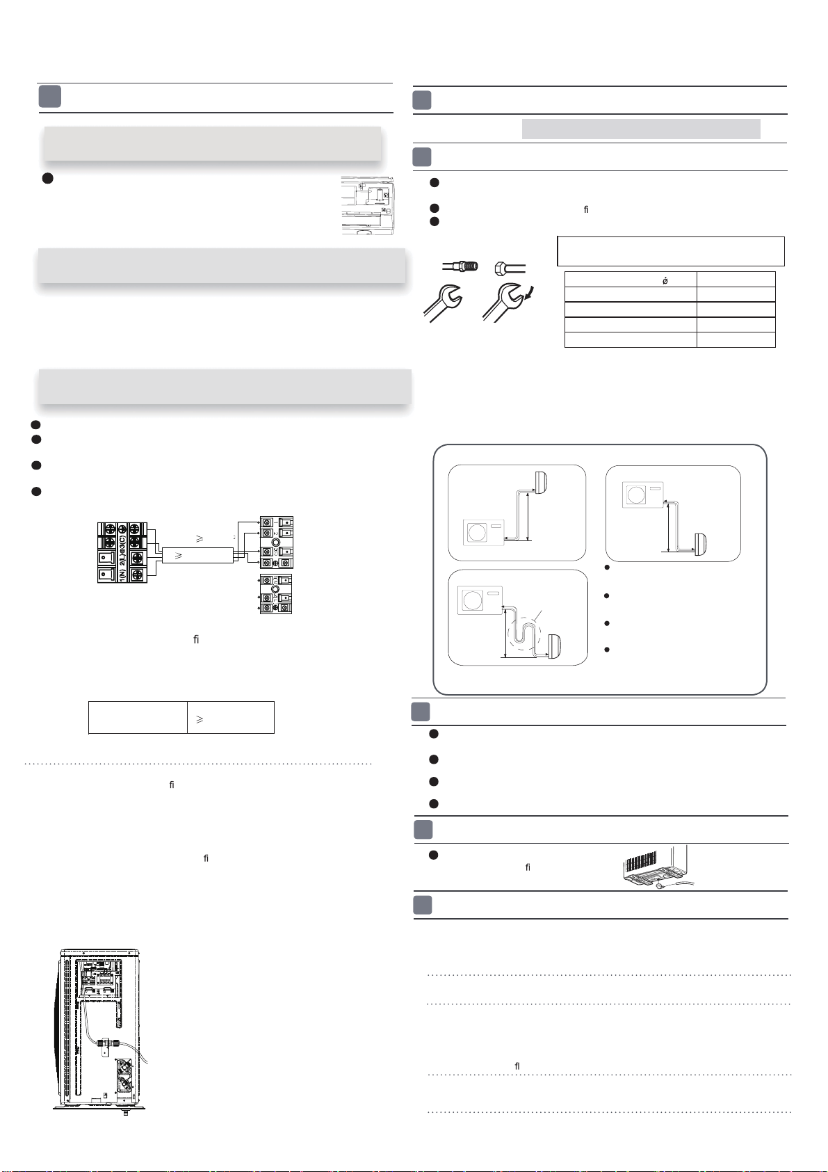
1. If the supply cord is damaged, it must be replaced by the manufacturer or its
service agent or a similar quali
ed person. The type of connecting wire is
H05RN-F
or H07RN-F.
2. If the fuse on PC board is broken please change it with the
type of
T. 3.15A/250V.
3. The wiring method should be in line with the local wiring standard.
4. After installation, the power plug should be easily reached.
5. A breaker should be incorporated into
xed wiring. The breaker should be
all-pole
switch and the distance between its two contacts should be not less
than 3mm.
3
Outdoor unit
Indoor unit
A
B
Outdoor unit
Indoor unit
A
B
A
B
Outdoor unit
Indoor unit
Oil trap
Outdoor unit
Install according to Drawing for the installation of indoor and
outdoor units
To bend a pipe, give the roundness as large as possible not to crush the pipe ,
and the bending radius should be 30 to 40
mm or longer.
Connecting the pipe of gas side
rst makes working easier.
The connection pipe is specialized for R410A.
Use the same method on indoor unit. Loosen the screws on
terminal block and
insert the plugs fully into terminal block, then tighten the screws.
Insert the cable according to terminal number in the same manner as the indoor
unit.
If wiring is not correct, proper operation can not be carried out and controller
may be damaged.
Fix the cable with a clamp.
Installation of Outdoor Unit
Half union
Flare nut
Torque wrench
CAUTION
Be careful that matters, such as wastes of sands, etc. shall not enter the pipe.
The standard pipe length is 5m. If it is over 7m, the function of the unit will be
affected. If the pipe has to be lengthened, the refrigerant should be charged,
according to 20 g/m. But the charge of refrigerant must
be conducted by profes-
sional air conditioner engineer. Before adding additional refrigerant, perform air
purging from the refrigerant pipes and indoor unit using a vacuum pump,then
Spanner
Forced fastening without careful centering may
damage the threads and cause a leakage of gas.
Pipe Diameter( ) Fastening torque
Liquid side6.35mm(1/4") 18N.m
Liquid/Gas side9.52mm(3/8") 42 N.m
Gas side 12.7mm(1/2") 55N.m
Gas side 15.88mm(5/8") 60 N.m
1
Connection of pipes
2
charge additional refrigerant.
Connection
3
If the drain-elbow is used,
please attach it as gure. (Note:
Only for heat pump unit.)
Detach the service port’s cap of
1.
3-way valve, the valve rod’s cap for 2-way valve
and 3-way’s, connect the service port into the
projection of charge hose (Iow)
for gaugemanifold.
Then connect the projection of charge hose (center) for gau-
gemanifold into vacuum pump.
Open the handle at Iow in
2.
gaugemanifold, operate vacuum pump. If the scale-
moves of gause (Iow) reach vacuum condition in a moment, check
1. again.
Vacuumi
ze for over 15min.And check the level gauge which should read -0.1MPa
3.
(76 cm Hg) at Iow
pressure side. After the
completion of vacuumizing, close the
handle ‘Lo’ in gaugemanifold and stop the operation of the vacuum pump. Check
condition of the scale and hold it for 1-2min. If the scale-moves back in spite of
tightening, make
aring work again, the return to the beginning of 3 .
Attaching Drain-Elbow
4
Purging Method:To use vacuum pump
5
Open the valve rod for the 2-way valve to an angle of4.
anticlockwise 90 degrees.
After 6 seconds, close the
2-way valve and make the
inspection of gas leakage.
4
Connecting the indoor/outdoor Electric Cable
Max.Elevation:
In case the elevation A is more
than 5m, oil trap shoud be
installed every 5~7m
Max. Length:
In case the pipe length B is
more than 7m, the refrigerant
should be charged, according
to 20 g/m for 05-13K and 50g/m for
05-13K:Amax=10m
18-24K:Amax=15m
05-13K:Bmax=15m
18-24K:Bmax=25m
18-24K.
R
emove terminal cover at rig
ht bottom corner of
indoor unit, then take
off wiring cover by removing
its screws.
Removing the wiring cover
1. Insert from outside the room cable into left side of the wall
hole, in which the pipe has already existed.
2. Pull out the cable on the front side, and connect the cable
making a loop.
When connecting the cable, con
rm the terminal number of indoor and
o
be carried out and will cause defect.
utdoor units carefully. If wiring is not correct, proper operation can not
Insert the cable from the back
side of the unit, then pull it out
on the front side.
Loosen the screws and insert
the cable ends fully into
terminal block, then
tighten the screws.
Pull the cable slightly to
make sure the cables have
been properly inserted and
tightened.
After the cable connection,
never fail to fasten the connected cable with the
wiring cover.
When connecting the cable after installing the indoor unit
When connecting the cable before installing the indoor unit
Note:
Connecting wiring
4G1.0mm
2
{
POWER
-mod 09-24: 3G2.5mm
Indoor unit
Outdoor unit
4G1.5mm
2
Power cable:
6.Please consult your reseller and/or installer to determine if you have a DRED
appliance.
Connect output from your home's electricity power meter (where
(This function is unavailable on some models.)
available) to the RJ45 connector on the outdoor unit, as shown.
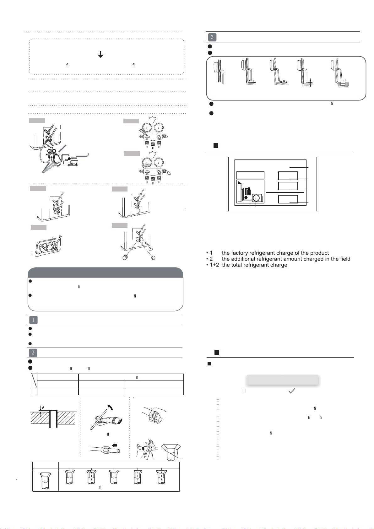
Open
No gas leakage?
5.
Detach the charge hose
6.
from the service port,
open 2-way valve and 3-way. Turn
the valve rod anticlockwiseuntil hitting lightly.
In case of gas leakage, tighten parts of pipe connection. If
leakage stops, then proceed 6. steps
If it does not stop gas leakage, discharge whole refrigerants
from the service
port. After
aring work again and vacuumize, ll up prescribed
refrigerant from the gas cylinder.
Anti countercurrent joint
Gaugemanifold(for
R32)
2-way valve Liquid Side
3-way valve Gas Side
Vacuum pump(for R32)
Tube(for R32)
Close
2-way valve
3-way valve
Open 90
O
2-way valve
3-way valve
2-way valve
3-way valve
2-way valve
3-way valve
Valve rod cap
Valve rod cap
Service port cap
To prevent the gas
leakage, turn the service
port’s cap, the valve rod’s cap for 2-way
valve and 3-way’s a little more
than the point where the torque increases suddenly.
After attaching the each caps, check the gas leakage around the caps.
7.
8.
Step 1.
Step 2.
Step 3.
Step 7.
Step 6.
Step 4.
The power source must be exclusively used for air
conditioner. (Over I0A)
In the case of installing an air conditioner in a moist place,
please install an ea-
For installation in other places, use a circuit breaker as far
as possible.
Pipe cutting is carried out with a pipe cutter and burs must
be removed.
After inserting the
are nut, aring work is carried out.
If the refrigerant of the air conditioner leaks, it is necessary to discharge all the
refrigerant. Vacuumize rst, then
charge the liquid refrigerant into air conditio-
ner according to the amount marked on the name plate.
Please do not let other cooling medium, except speci
ed one (R32), or air
enter into the cooling circulation system. Otherwise, there will be abnormal
high pressure in the system to make it crack and lead to personal injuries.
Power Source Installation
Cutting and Flaring Work of Piping
Flare tooling die
1.Cut pipe
2.Remove burs
3.Insert the
are nut
CAUTION
Flare tool for R32 Conventional are tool
Clutch-type clutch-type(Rigid-type) Wing-nut type (Imperial-type)
A 0~0.5mm 1.0~1.5mm 1.5~2.0mm
rth leakage breaker.
4.Flare pipe
Lean
Damage of
are Crack Partial Too outside
tcerrocnItcerroC
On Drainage
It becomes
high midway.
The gap with the
ground is too smal
There is the bad
smell from a ditch
It waves.
The end is imm-
ersed in water.
Please install the drain hose so as to be downward slope without fail.
Please don’t do the drainage as shown below.
Please pour water in the drain pan of the indoor unit, and
is carried out surely to outdoor.
In case that the attached drain hose is in a room, please
apply heat insulation to
Less than
5cm
con
rm that drainage
it without fail.
4
Check Items for Test Run
Put check mark
in boxes
Gas leak from pipe connecting?
Heat insulation of pipe connecting?
Are the connecting wirings of indoor and outdoor
rmly
Is the connecting wiring of indoor and outdoor
rmly xed?
Is drainage securely carried out?
Is the earth line securely connected?
Is the indoor unit securely xed?
Is power source voltage abided by the code?
Is there any noise?
Is the lamp normally lighting?
Are cooling and heating (when in heat pump) performed normally?
Is the operation of room temperature regulator normal?
Please kindly explain to our customers how to operate
through the instruction manual.
Check for Installation and Test Run
inserted to the terminal block?
Refrigerant charge label
1
1+2=
kg
R32
2
kg
2=
1=
B
C
D
F E
kg
A
This product contains fluorinated greenhouse gases covered by
the Kyoto Protocol. Do not vent into the atmosphere.
Refrigerant type:R32
GWP* value:675
GWP=global warming potential
Please fill in with indelible ink,
and
on the refrigerant charge label supplied with the product.
The filled out label must be adhered in the proximity of the product
charging port (e.g. onto the inside of the stop value cover).
A contains fluorinated greenhouse gases covered by the Kyoto
Protocol
B factory refrigerant charge of the product: see unit name plate
C additional refrigerant amount charged in the field
D total refrigerant charge
E outdoor unit
F refrigerant cylinder and manifold for charging
Contains fluorinated greenhouse gases
covered by the Kyoto Protocol
Step 5.