Loading ...
Loading ...
Loading ...
Connector Wiring Diagram
Domestic Air Conditioner
1 .Service Diagnosis
1 .1.1 Caution for Diagnosis
The operation lamp flashes when any of the following errors is detected.
1.Whenaprotection device of the indoor or outdoor unit is activated or when the thermistor malfunctions,
disabling equipment operation.
2.Whenasignal transmission error occurs between the indoor and outdoor units.In either case, conduct the
diagnostic procedure described in the following pages.
31
1 .1.2 Problem Symptoms and Measures
erusaeMfosliateDmetIkcehCmotpmyS
None of the units
operates
Check the power supply. Check to make sure that the rated voltage is supplied.
Check the indoor PCB Check to make sure that the indoor PCB is broken
Operation
sometimes stops.
Check the power supply.
A power failure of2to 10 cycles can stop air conditioner
operation.
Equipment
operates but
does not cool, or
does not heat
(only for heat
pump)
Check for faulty operation
of the electronic
expansion valve.
Set the units to cooling operation, and compare the
temperatures of the liquid side connection pipes of the
connection section among rooms to check the opening and
closing operation of the electronic expansion valves of the
individual units.
Diagnosis by service port
pressure and operating
current.
Check for insufficient gas.
Large operating
noise and
vibrations
Check the installation
condition.
Check to make sure that the required spaces for
installation (specified in the Technical Guide, etc.) are
provided.
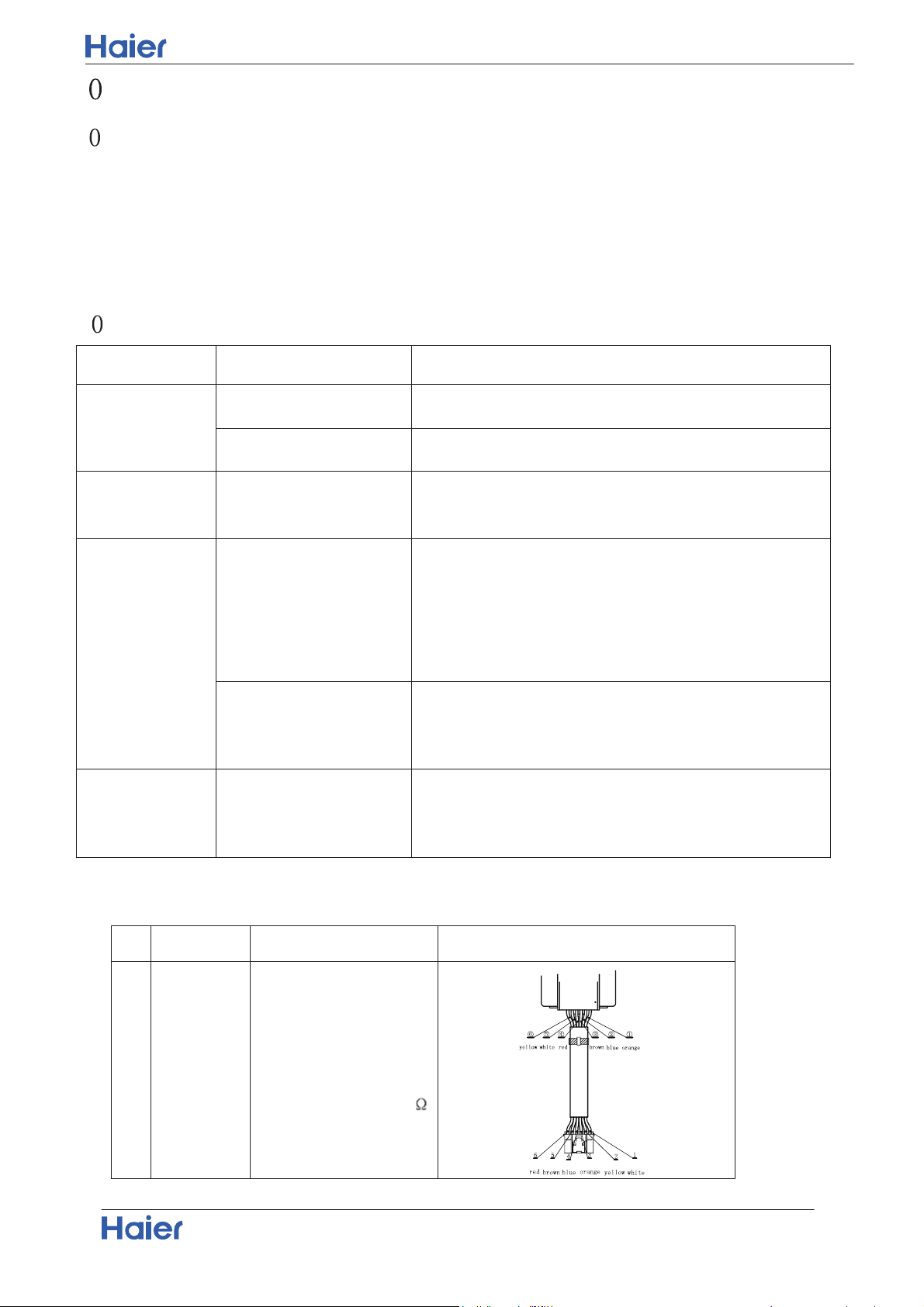
10.2 Parameter of primary electronic appliance
N O N am e Pa ra m eter Pic ture
1
Rated voltage:12V
ELECTRIC
EXPANSION
VALVE
Valve orifice : Φ1.8mm
Coil resistance 46±3.7
Loading ...
Loading ...
Loading ...