Loading ...
Loading ...
Loading ...
EN
31
Installation
www.bora.com
Release the power supply cable
To release the power supply cable for the fan [1] from
the universal control unit [6] you need a small flat
screwdriver.
Disconnect the universal control unit’s power supply
cable from the power supply [8].
Make sure that there is no power to the appliance.
Use the flat screwdriver to loosen the lock on the fan
power supply cable plug.
To do this, insert the flat screwdriver into the gap in
the socket.
Press the lock down gently.
Use the flat screwdriver to gently lever the plug of the
power supply cable out of the universal control unit’s
socket.
Now disconnect the power supply cable from the
socket.
Check the plug and the socket for damage.
Do not use damaged components.
Contact your BORA specialist supplier to replace any
damaged components.
Connecting the additional fan
Connect the fan control line [2] to the universal control
unit [5].
Connect the fan mains connection line [1] to the
universal control unit [7].
Check all the plug connections to ensure that they are
secure.
6.11.4 Establishing the power connection
Connect the mains connection line for the extraction
system (PKAS, PKASAB) or the mains connection
cable for the universal control unit (PKA) to the power
supply.
Put the cooktop extractor into operation
(see the Operation section).
Check that all the functions are working correctly.
6.12 Configuration menu
Once installation is complete, you must configure
certain basic settings for your cooktop extractor (see
also the supplementary information sheet on initial
commissioning).
6.12.1 Accessing the configuration menu
Turn the knob ring from the 12 o-clock position to the
11 o’clock position.
A0 appears in the control knob display.
Now press the touch surface for 5 seconds.
This accesses the configuration menu and
C
is shown
on the control knob display.
86
4
2
1
75
3
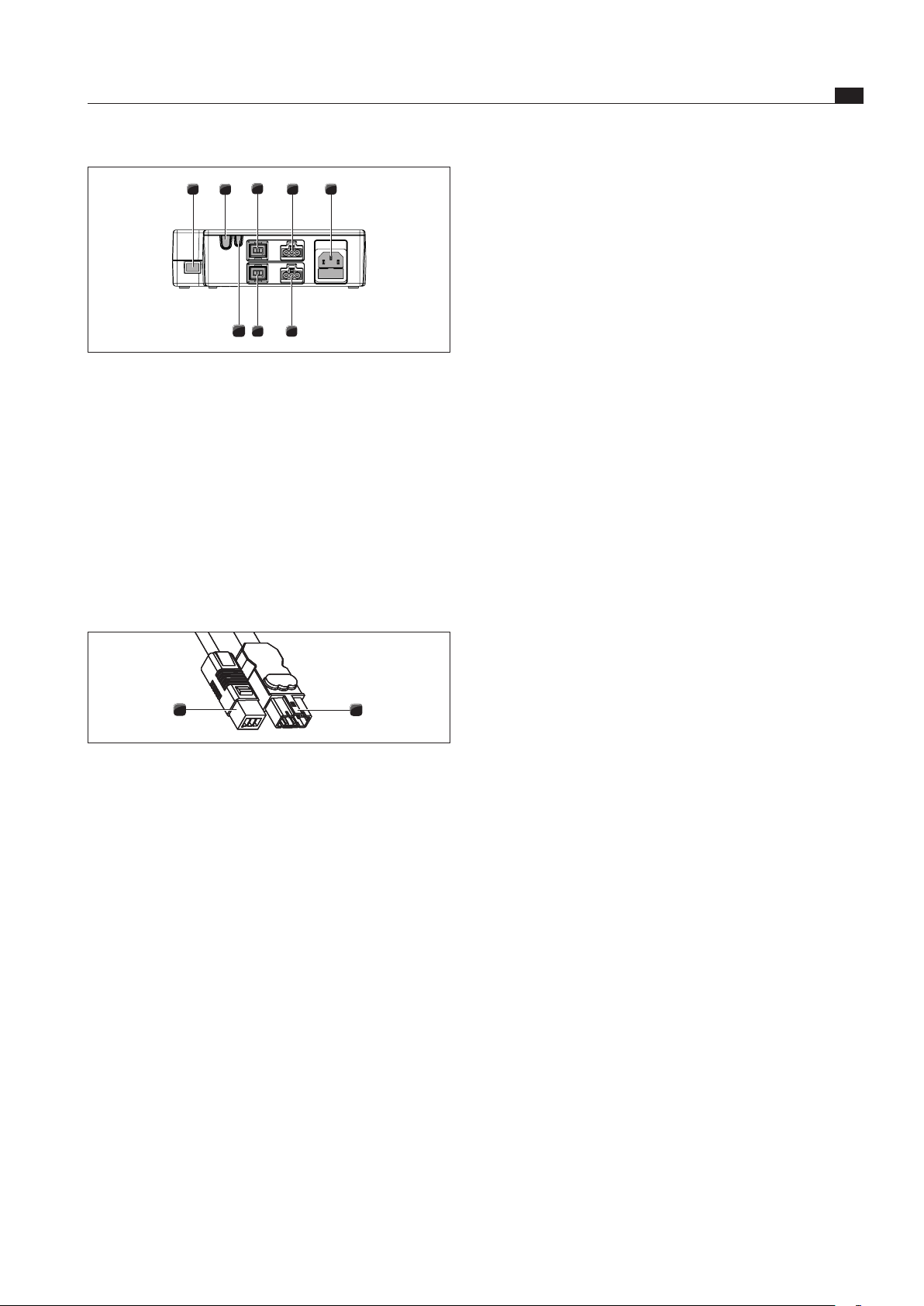
Fig. 6.48 Connections on the universal control unit
[1] CAT 5 communication cable
[2] Home Out
[3] Home In
[4] Fan 1 control line
[5] Fan 2 control line
[6] Fan 1 power supply cable
[7] Fan 2 power supply cable
[8] Power supply cable with microfuse
Use the CAT 5 communication cable to connect the
connection for the control unit on the cooktop extractor
to the connection on the universal control unit [1].
2
1
Fig. 6.49 Connection plug of the plinth fan
[1] Connection plug of the plinth fan power supply cable
[2] Connection plug of the plinth fan control line
Connect the plinth fan’s control line [2] to the universal
control unit.
Connect the plinth fan’s power supply cable [1] to the
universal control unit .
Loading ...
Loading ...
Loading ...