Loading ...
Loading ...
Loading ...
EN
28
Installation
www.bora.com
Preparing connection cables for external
switching equipment
Use connection cables of the following types and
manufacturers to connect external switchgear.
Contact Connection cable
Home In H03VV-F 2 x 0.5 mm²
Home Out H03VVH2-F 2 x 0.75 mm²
Tab. 6.6 Connection cable
INFO The connection cable is only intended for internal
use in buildings, private households, kitchens or
offices.
INFO The overall length of the connection cable for
external switching equipment must not exceed
10 m!
For reasons of electromagnetic compatibility, all
connection cables from external switch devices must be
filtered with a ferrite sleeve. This is not included in the
scope of delivery.
Use the order code UFH (universal filter sleeve) to
order the filter sleeve from your specialist supplier or
contact BORA via the website at www.bora.com.
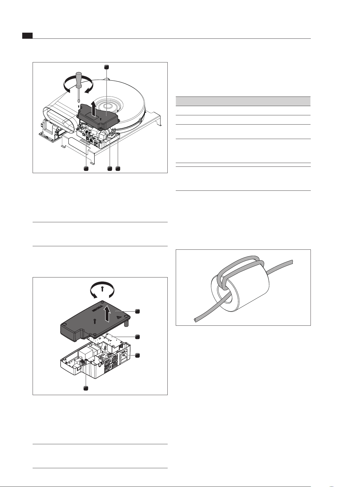
Fig. 6.40 Wrap the connection cable round the ferrite sleeve
three times
Wrap the connection cable around the ferrite sleeve
3 times to create the desired filter performance.
Ensure that the cable end protrudes at least 120 mm
from the sleeve.
Prepare the connection cable in accordance with the
prescribed stripping lengths.
4 3 2
1
Fig. 6.38 Open the cover of the control unit
[1] Cover
[2] Housing
[3] Electronic unit
[4] Switch contact terminals
INFO The electronic unit [3] can contain residual
charge. You must therefore be careful not to
touch the exposed contacts on the electronic unit!
PKA preparation
Remove the screws from the universal control unit.
Lift up the cover [1].
1
2
4
3
Fig. 6.39 Open the universal control unit’s cover
[1] Cover
[2] Electronic unit
[3] Base unit
[4] Switch contact terminals
INFO The electronic unit [2] can contain residual
charge. You must therefore be careful not to
touch the exposed contacts on the electronic unit!
Loading ...
Loading ...
Loading ...